AMPAK Technology AP6356SDXX WLAN module for 802.11abgn(2x2) + 11ac+BT4.1 User Manual
AMPAK Technology Inc. WLAN module for 802.11abgn(2x2) + 11ac+BT4.1
Contents
- 1. User Manual
- 2. User Manuel
User Manual

AMPAK Technology Inc. www.ampak.com.tw Proprietary & Confidential Information i
Doc. NO:
AMPAK
AP6356SDXX
Evaluation Kits
User manual
Version 1.0
Revision History
Date
Revision Content
Revised By
Version
2015/12/28
Initial released
Aron
1.0

AMPAK Technology Inc. www.ampak.com.tw Proprietary & Confidential Information
Doc. NO:
1
Federal Communication Commission Interference Statement
This device complies with Part 15 of the FCC Rules. Operation is subject to the
following two conditions: (1) This device may not cause harmful interference, and
(2) this device must accept any interference received, including interference that
may cause undesired operation.
This equipment has been tested and found to comply with the limits for a Class B
digital device, pursuant to Part 15 of the FCC Rules. These limits are designed
to provide reasonable protection against harmful interference in a residential
installation. This equipment generates, uses and can radiate radio frequency
energy and, if not installed and used in accordance with the instructions, may
cause harmful interference to radio communications. However, there is no
guarantee that interference will not occur in a particular installation. If this
equipment does cause harmful interference to radio or television reception, which
can be determined by turning the equipment off and on, the user is encouraged to
try to correct the interference by one of the following measures:
- Reorient or relocate the receiving antenna.
- Increase the separation between the equipment and receiver.
- Connect the equipment into an outlet on a circuit different from that
to which the receiver is connected.
- Consult the dealer or an experienced radio/TV technician for help.
FCC Caution: Any changes or modifications not expressly approved by the party
responsible for compliance could void the user's authority to operate this
equipment.
This transmitter must not be co-located or operating in conjunction with any other
antenna or transmitter.

AMPAK Technology Inc. www.ampak.com.tw Proprietary & Confidential Information
Doc. NO:
2
Radiation Exposure Statement:
This equipment complies with FCC radiation exposure limits set forth for an
uncontrolled environment. This equipment should be installed and operated with
minimum distance 20cm between the radiator & your body.
This device is intended only for OEM integrators under the following conditions:
1) The antenna must be installed such that 20 cm is maintained between the
antenna and users, and
2) The transmitter module may not be co-located with any other transmitter or
antenna.
As long as 2 conditions above are met, further transmitter test will not be required.
However, the OEM integrator is still responsible for testing their end-product for
any additional compliance requirements required with this module installed
IMPORTANT NOTE: In the event that these conditions can not be met (for
example certain laptop configurations or co-location with another transmitter),
then the FCC authorization is no longer considered valid and the FCC ID can not
be used on the final product. In these circumstances, the OEM integrator will be
responsible for re-evaluating the end product (including the transmitter) and
obtaining a separate FCC authorization.
End Product Labeling
This transmitter module is authorized only for use in device where the antenna
may be installed such that 20 cm may be maintained between the antenna and
users. The final end product must be labeled in a visible area with the following:
“Contains FCC ID:ZQ6-AP6356SDXX”. The grantee's FCC ID can be used only
when all FCC compliance requirements are met.
Manual Information To the End User
The OEM integrator has to be aware not to provide information to the end user
regarding how to install or remove this RF module in the user’s manual of the end
product which integrates this module.
The end user manual shall include all required regulatory information/warning as
show in this manual.
AMPAK Technology Inc. www.ampak.com.tw Proprietary & Confidential Information
Doc. NO:
3
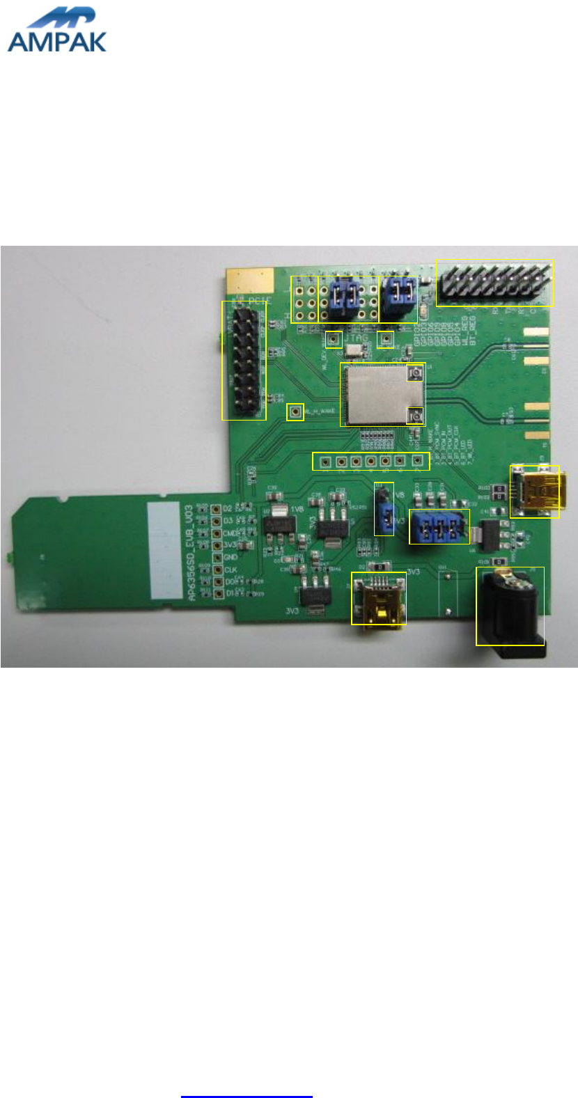
1. AP6356SDXX Evaluation Board Introduction
AP6356SDXX Evaluation board (EVB) likes as figure1. That is designed for IEEE802.11
a/b/g/n/ac 2x2 WLAN with integrated Bluetooth. It is subject to provide a convenient
environment for customer’s verification on WiFi or Bluetooth function. There are many
controller pins and reserved GPIO on Evaluation board which describes as below.
Figure1. Top view of AP6356SDXX EVB
Interface highlights:
1. U1: AP6356SDXX SIP module.
2. J1: UART interface connects with UART transport board for BT.
3. J80: PCIE interface connects with PCIE transport board for WIFI.
4. J3: Enable(H) or disable(L) Bluetooth and WiFi function.
5. J4: PCIE interface strapping option
6. J5: 5V DC adaptor input connector.
7. J6: 3V3 RF/ VBAT / WL_VIO / BT_VIO for main system I/O power path.
8. J7/J9: 5V DC mini USB input connector.
9. J10: GPIO_2 (input/output) and GPIO_3 (input/output)
10. J11: WL_VIO power path for 1V8 or 3V3 selection.
11. A1: I-PEX connector let RF signal in/out path, you could connect with RF cable or
J10
J4
J3
J1
A2
U1
A1
J80
ct2
ct3
ct4
J7
J5
J9
J11
J6
ct1
AMPAK Technology Inc. www.ampak.com.tw Proprietary & Confidential Information
Doc. NO:
4
Dipole antenna.
12. A2: I-PEX connector let RF signal in/out path, you could connect with RF cable or
Dipole antenna.
13. Ct1-Ct4: WLAN and BT control pins, strongly recommended WL_H_WAKE(IRQ)
connected to MCU.
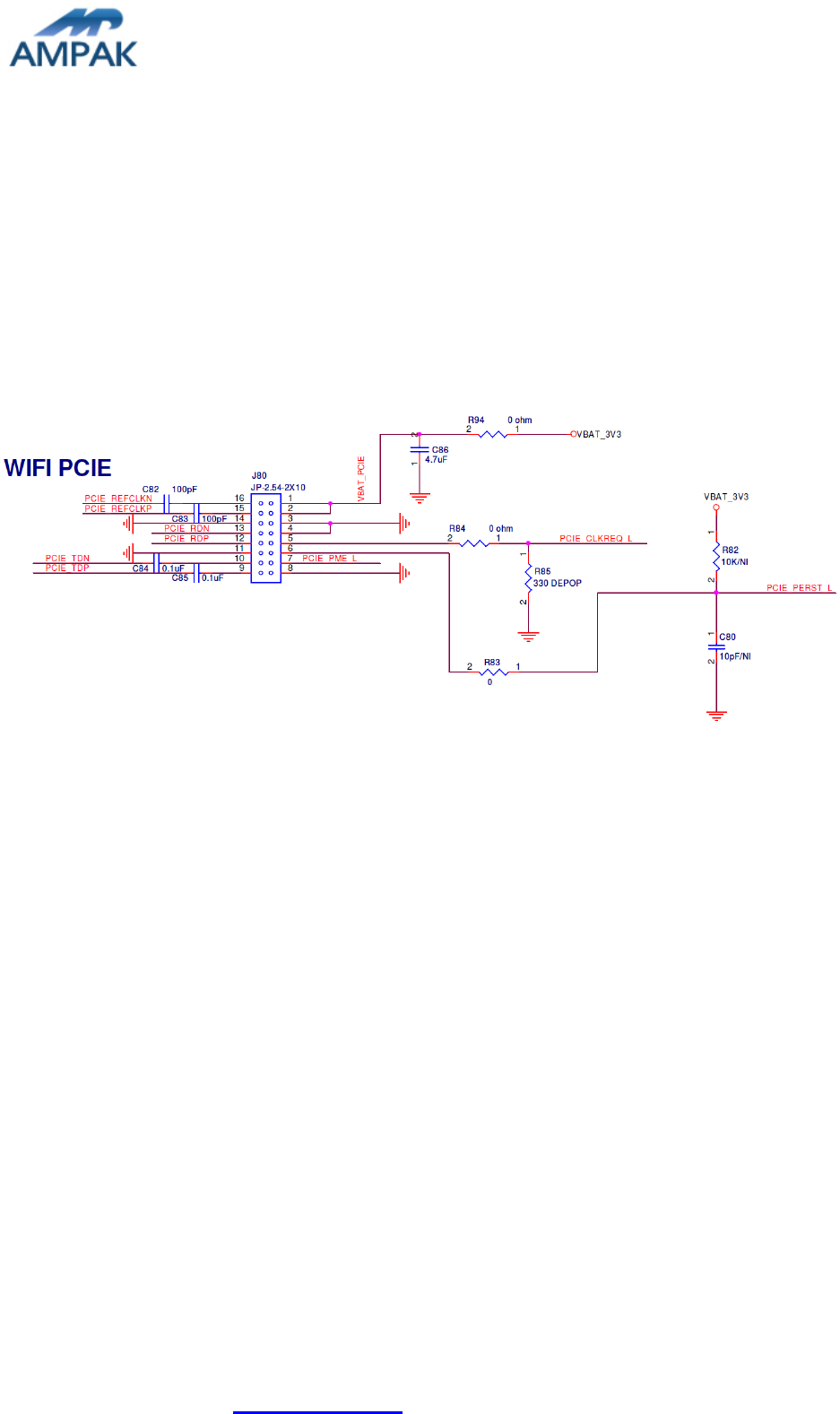
2. WiFi function verification step
WIFI PCIe: PCIe interface definition as below J80 dip connector and this should be used
3.3V for PCIe voltage.
Figure3. WiFi verification connection interface to Host PCIE
Hardware Setup:
Refer to Figure3 PCIE pin definition connects the J80 interface of
AP6356SDXX evaluation board to Host PCIE control interface.
Connects an external antenna at I-PEX connector on the evaluation board.
Note to the VDDIO voltage level should be the same with GPIO voltage level of
Host CPU. (VDDIO 3.3V or 1.8V selection by jump J11)
Pull High J4 are necessary .
WiFi software setup:
Please follow up software guideline of Ampak official released.
AMPAK Technology Inc. www.ampak.com.tw Proprietary & Confidential Information
Doc. NO:
5
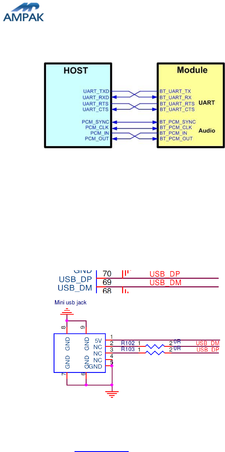
3. Bluetooth function verification step
UART:
Figure4. Bluetooth verification connection interface to Host UART
Hardware Setup:
Refer to Figure4 UART pin definition connects the J1 interface of AP6356SDXX
evaluation board to Host UART control interface.
Connects an external antenna at I-PEX connector on the evaluation board.
Note to the VDDIO voltage level should be the same as GPIO voltage level of
Host CPU.
USB:
Figure5. Bluetooth verification connection interface to Host USB

AMPAK Technology Inc. www.ampak.com.tw Proprietary & Confidential Information
Doc. NO:
6
Hardware Setup:
Refer to Figure5 USB pin definition connects the J9 interface of AP6356SDXX
evaluation board to Host USB control interface.
Connects an external antenna at I-PEX connector on the evaluation board.
WiFi and Bluetooth software setup:
Please follow up software guideline of Ampak official released.