AMPAK Technology WMDA612ANTX Wireless Home Digital Interface Transmitter Dongle User Manual FCC WMDA 612ANx
AMPAK Technology Inc. Wireless Home Digital Interface Transmitter Dongle FCC WMDA 612ANx
Contents
- 1. User Man_ZQ6-WMDA612ANRX
- 2. User Man_ZQ6-WMDA612ANTX
User Man_ZQ6-WMDA612ANRX
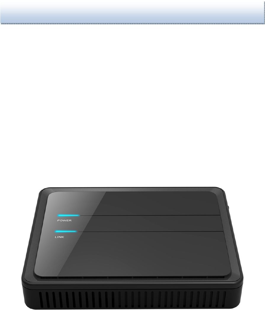
Wireless HDMI Dongle
Quick Installation
Guide/ User Manual
WMAD-612AN

WDMA-612AN User Manual
1
About this product
Purpose
The purpose of this document is to provide installation information for Wireless
HDMI dongle products.
Intended audience
This document is for individuals who install Wireless HDMI dongle.
How to use this document
Use this guide to install Wirless HDMI dongle.
Safety information
WARNING: The following information lists the safety reminders for
installation and maintenance personnel.
Read all instructions before attempting to unpack, install, operate, or connect
power to this product. Please remember the following when you unpack and
install this equipment:
• Always follow basic safety precautions to reduce the risk of fire, electrical
shock and injury.
• To prevent fire or shock hazard, do not expose the unit to rain, moisture or
install this product near water. Never spill any form of liquid on or into this
product.
• Do not insert any sharp object into the products module openings or empty
slots. Doing so may accidentally damage its parts.
• Do not attach the power supply cable on building surfaces or floorings. Rest
the power cable freely without any obstacle or heavy items piled on top of it.
Refrain from abusing, stepping or walking on the cable.
• To protect the equipment from overheating, do not block the slots and
openings in the module housing that provide ventilation.
• Electrostatic discharge (ESD) can permanently damage semiconductor
devices. Always follow ESD-prevention guidelines for equipment handling and
storage.

WDMA-612AN User Manual
2
Eco-environmental statements
The statements that follow are the eco-environmental statements that apply to
WMDA-612AN Wireless HDMI dongle.
Packaging collection and recovery requirements
Countries, states, localities, or other jurisdictions may require that systems be
established for the return and/or collection of packaging waste from the consumer,
or other end user, or from the waste stream. Additionally, reuse, recovery, and/or
recycling targets for the return and/or collection of the packaging waste may be
established. For more information regarding collection and recovery of packaging and
packaging waste within specific jurisdictions, please contact the Sonic Devices
Technologies Field Services / Installation - Environmental Health and Safety
organization.
1. Safety Guidelines
In order to reduce the risk of fire, electric shock and injury, please adhere to the
following safety guidelines.
Carefully follow the instructions in this manual; also follow all instruction labels on
this device.
Only use the power adapter supplied with the device.
Do not spill liquid of any kind on this device.
Do not place the unit on an unstable stand or table; the unit may drop and become
damaged.
Do not expose this unit to direct sunlight.
Do not place any hot devices close to this unit, as it may degrade or cause
damage to it.
Do not place any heavy objects on top of this unit.
Do not use liquid cleaners or aerosol cleaners. Use a soft dry cloth for cleaning.
WDMA-612AN User Manual
3
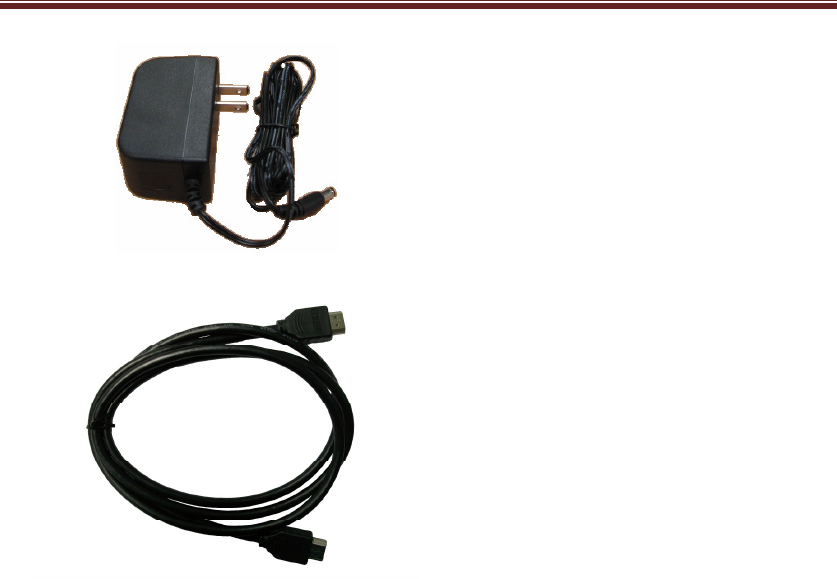
2. Packaging
This package consists of the following items:
WDMA-612AN_RX
WMDA-612AN_TX
WDMA-612AN User Manual
4
AC Adapter
Vin =230V 50Hz
Vout =12V; 1A
HDMI cables *2
WDMA-612AN User Manual
5
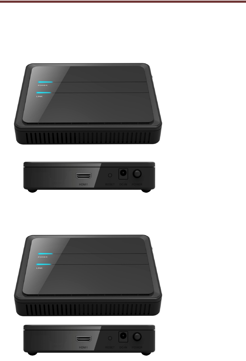
3. Structure
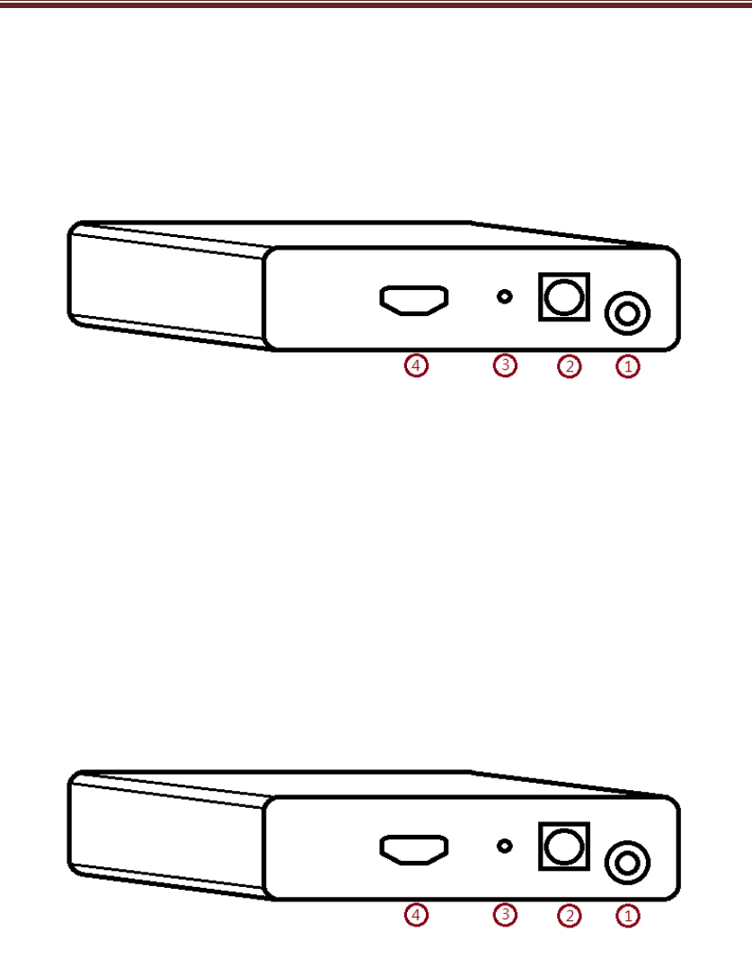
WMDA-612AN_RX
1.Power Switch On/Off
2.Power Input
3.Reset Button
4.HDMI Output Port
WMDA-612AN_TX
1.Power Switch On/Off
2.Power Input
3.Reset Button
4.HDMI Input Port
WDMA-612AN User Manual
6
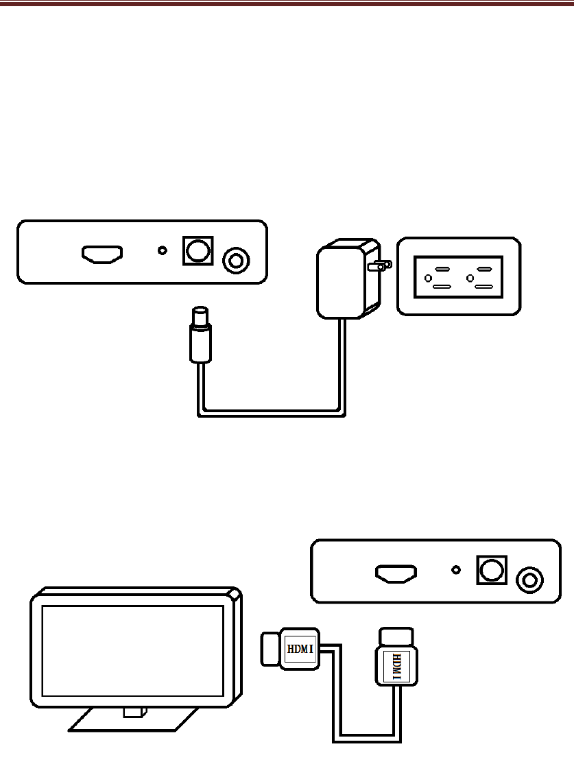
4. Installation and Use
WMDA-612AN_RX
Step.1 Plug in power.
Step.2
Plug into Television HDMI input.
.
WDMA-612AN User Manual
7
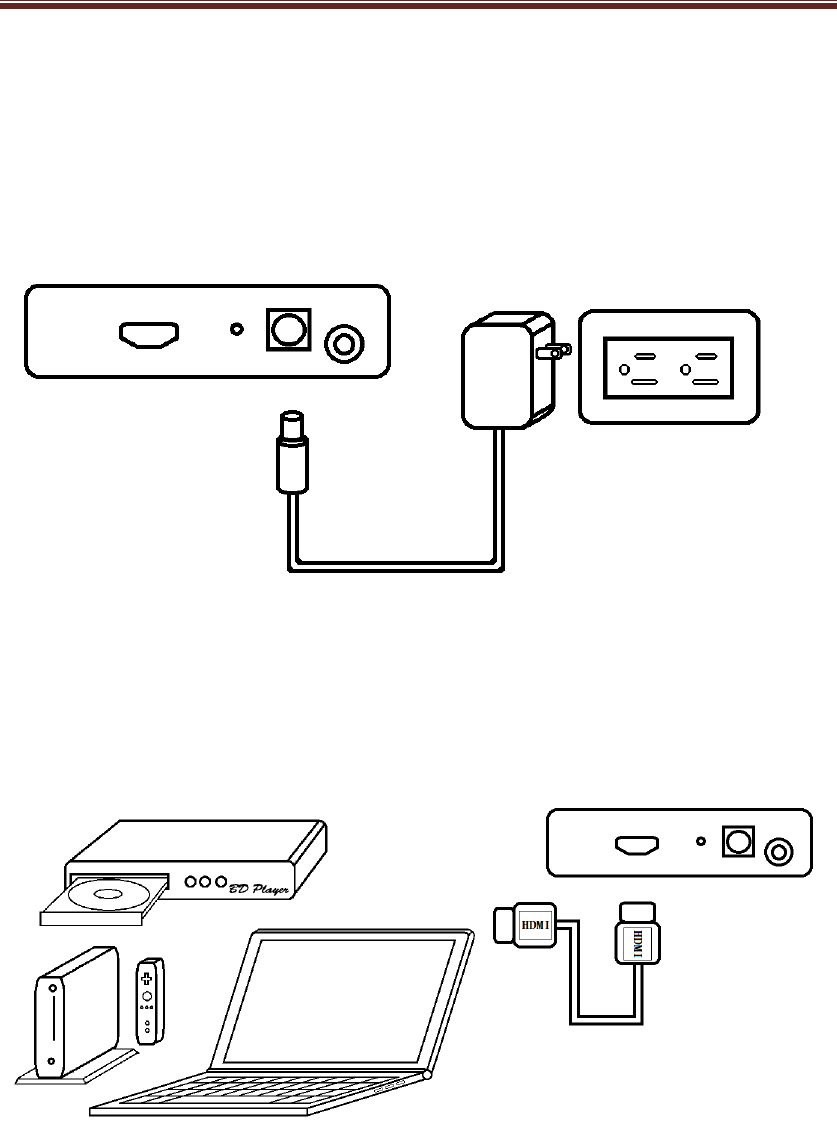
WMDA-612AN_TX
Step.3 Plug in power.
Step.4 Plug in Video source.(ex. DVD/BD player, Game console,
Set-Top Box or any source with HDMI output.)

WDMA-612AN User Manual
8
5. Specifications
WMDA-612AN_RX
Product Name Wireless Home Digital Interface Receiver Dongle
Model Number WMDA-612_RX
Host Interface HDMI type A socket x1 for output to TV/Display
Chipset solution
MCU- ST/ STM32F103
HDMI- SiI9134
BBP- Amimon/AMN2220
RF- Amimon/AMN3210
DFS- AIROHA/ AL7230 (Option)
Memory 4Mbit Flash
512Mb DDRII
Switch Reset Button x 1, Power ON/OFF Button x 1,
Red Power off
Power
Blue Power on
Red Wireless unconnected
Blue Wireless connected
LED
Wireless
Red&Blue blink
Search signal
Dimensions PCBA 160.0L x 80.0W x 15.0H (mm)
Operating Voltage 12V +/- 5%
Power
Consumption 6.6 Watt
Antenna
Total 6 PCB printed antenna ; Peak Gain:3.5 dBi
1 antenna for Transmitter & Receiver
4 antennas for Receiver
1 antenna for DFS Only (Option)
Transmit Power
(E.I.R.P.) 17.5 dBm (max.)
Channel Bandwidth 20MHz / 40MHz
Modulation Downlink: OFDM 16-QAM
Uplink: OOK
Uplink Data Rate
User-defined downlink channel with up to 1 Mbps for data and control
User-defined uplink channel with up to 100 Kbps for data and control

WDMA-612AN User Manual
9
Less than 1mSec latency between video source and video sink
Network mode Uni-cast / Broad cast (Option)
DFS Support
Low-end DFS without additional RF Chain
High-end DFS with additional RF Chain allowing to monitor additional DFS
channel and immediate switch in case of radar detection
Video resolutions
HD: 480i, 480p, 576i, 576p, 720p, 1080i, 1080p
PC: VGA (640x480), SVGA (800x600), XGA (1024x768),
Panel: 854x800, 1280x768, 1366x768, 1920x1080
3D video: 1280x720 @ 48Hz / 60Hz, 1920x1080 @ 48Hz / 60Hz)
3D gaming: 1280x720 @ 100Hz / 120Hz
Audio Up to 18 Mbps audio stream:
I2S: Up to eight PCM channels (sampled up to 192 KHz x 24 bit).
SPDIF: Including AC-3, DTS, Dolby 5.1, Digital
Operating Range 33~50 feet Indoor. The transmission quality varies in the system board and
surrounding environment.
Temperature Range 0 ~ 40°C (Operating), -20~60°C (Storage)
WMDA-612AN_TX
Product Name Wireless Home Digital Interface Transmitter Dongle
Model Number WMDA-612AN_TX
Host Interface HDMI type A socket x1 for input from HDMI/DVI source
Chipset solution
MCU- ST/STM32F105
HDMI- SiI9233
BBP- Amimon/AMN2120
RF- Amimon/AMN3110
Memory 4Mbit Flash
Switch Reset Button x 1, Power ON/OFF Button x 1
Red Power off
Power
Blue Power on
Red Wireless unconnected
Blue Wireless connected
LED
Wireless
Red&Blue
blink Search signal
Dimensions PCBA 160.0L x 105.0W x 15.0H (mm)
Operating Voltage 12V +/- 5%
Power
Consumption
7.92 Watt
Antenna Total 5 PCB printed antenna; Peak Gain: 3.5 dBi

WDMA-612AN User Manual
10
4 antenna for Transmitter
1 antenna for Receiver
Transmit Power
(E.I.R.P.)
19.5 dBm (max.)
Channel Bandwidth 20MHz / 40MHz
Modulation
Downlink: OFDM 16-QAM
Uplink: OOK
Downlink Data Rate
User-defined downlink channel with up to 1 Mbps for data and control
User-defined uplink channel with up to 100 Kbps for data and control
Less than 1mSec latency between video source and video sink
Network mode Uni-cast / Broad cast (Option)
Video resolutions
HD: 480i, 480p, 576i, 576p, 720p, 1080i, 1080p
PC: VGA (640x480), SVGA (800x600), XGA (1024x768)
Panel: 854x800, 1280x768, 1366x768, 1920x1080
3D video: 1280x720 @ 48Hz / 60Hz, 1920x1080 @ 48Hz / 60Hz)
3D gaming: 1280x720 @ 100Hz / 120Hz’
Audio -- I2S: Up to 8 PCM channels (sampled up to 192 KHz x 24 bit)
-- Optional audio down-sampling for efficient modem bandwidth control
SPDIF: Including AC-3, DTS
Operating Range 33~50 feet Indoor. The transmission quality varies in the system board and
surrounding environment.
Temperature Range 0 ~ 40°C (Operating), -20~60°C (Storage)

WDMA-612AN User Manual
11
7. Troubleshooting
No Image Displayed on screen:
Are the TX and RX units plugged in and
on?
Is the correct INP being used (press the
button and test it)
Is the TV on the correct input for the RX
unit? (cycle between TV inputs)
Is the "Link" light illuminated (carefully
reset if not)
Unit will not Link:
There is a finite range for the device,
and it varies depending on interference.
Move the TX and RX units closer
together, turn the units off, wait 25 sec,
then power them back on. This should
get the link.
No Power light:
Make certain the TX and RX units are
plugged in as shown in the diagram.
Check your power strip or wall socket to
make sure there is power, do other
devices power in that socket or on that
power strip? Turn off and turn on the
power. Make sure the switch is fully
depressed.

WDMA-612AN User Manual
12
8. FCC Statement
Federal Communication Commission
Interference Statement
This equipment has been tested and found to comply with the limits for
a Class B digital device, pursuant to Part 15 of the FCC Rules. These
limits are designed to provide reasonable protection against harmful
interference in a residential installation. This equipment generates, uses
and can radiate radio frequency energy and, if not installed and used in
accordance with the instructions, may cause harmful interference to
radio communications. However, there is no guarantee that
interference will not occur in a particular installation. If this equipment
does cause harmful interference to radio or television reception, which
can be determined by turning the equipment off and on, the user is
encouraged to try to correct the interference by one of the following
measures:
- Reorient or relocate the receiving antenna.
- Increase the separation between the equipment and receiver.
- Connect the equipment into an outlet on a circuit different from that
to which the receiver is connected.
- Consult the dealer or an experienced radio/TV technician for help.
FCC Caution: Any changes or modifications not expressly approved by
the party responsible for compliance could void the user's authority to
operate this equipment.
Operations in the 5.15-5.25GHz band are restricted to indoor usage only.

WDMA-612AN User Manual
13
This device complies with Part 15 of the FCC Rules. Operation is
subject to the following two conditions: (1) This device may not cause
harmful interference, and (2) this device must accept any interference
received, including interference that may cause undesired operation.
IMPORTANT NOTE:
Radiation Exposure Statement:
This equipment complies with FCC radiation exposure limits set forth for
an uncontrolled environment. This equipment should be installed and
operated with minimum distance 20cm between the radiator & your body.
This transmitter must not be co-located or operating in conjunction with
any other antenna or transmitter.