AMT DSR-101PLUS Digital Satellite Receiver User Manual
AMT Co., Ltd. Digital Satellite Receiver
AMT >
User Manual

User’s Guide
DIGITAL SATELLITE RECEIVER
DSR-101 PLUS +

Information contained in this manual is subject to change without notice. No part of this
publication may be copied, reproduced, or translated to another language for any
purpose.
FOR YOUR SAFETY
•Be sure to read the user manual before starting the operation of the receiver.
•Do not open the housing. The receiver contains high-voltage components and parts.
•Even after switching off the receiver still contains high-voltage for a while.
•Do not expose to rain or moisture.
•Do not make objects or fluid enter the housing through the ventilation slot. If any
spilt liquid went into to the housing, unplug the power cord and call your local
service provider.
•Do not place close to any heat source.
•Do not press with hard or heavy object.
•To protect possible malfunction by lighting, we recommend you to use power surge
unit. Call your local dealer for advise.
FOR YOUR SAFETY
II
INFORMATION TO THE USER
This equipment has been tested and found to comply with the limits for a Class B
digital device, pursuant to part 15 of the FCC Rules. These limits are designed to
provide reasonable protection against harmful interference in a residential installation.
This equipment generates, uses and can radiate radio frequency energy and, if not
installed and used in accordance with the instructions, may cause harmful
interference to radio communications. However, there is no guarantee that
interference will not occur in a particular installation. If this equipment does cause
harmful interference to radio or television reception, which can be determined by
turning the equipment off and on, the user is encouraged to try to correct the
interference by one more of the following measures:
-. Reorient or relocate the receiving antenna.
-. Increase the separation between the equipment and receiver.
-. Connect the equipment into an outlet on a circuit different from that to which
the receiver is connected.
-. Consult the dealer or an experienced radio/TV technician for help.
WARNING
Changes or modifications not expressly approved by the manufacturer
could void the user’s authority to operate the equipment.

For Your Safety
1. Before Getting Started 1
1.1 Main Features 1
1.2 Accessories 2
2. Controls and Functions 3
2.1 Front Pannel 3
2.2 Rear Pannel 4
2.3 Remote Control Unit 5
3. Connections 7
3.1 Connecting to the TV, VCR and Satellite Antenna 7
3.2 Connecting DiSEqC switch 7
3.3 Connecting to the TV, HiFi system 8
4. Settings and Operations 9
4.1 Basic Settings 9
4.2 Viewing TV(or Radio) 14
4.3 Other functions 18
4.4 System Settings 20
5. Appendix 23
5.1 Troubleshooting 23
5.2 Specification 23
5.3 Glossary 24
III
CONTENTS

1.1 Main Features
•Easy Menu Function
•TV Guide Function
•RF Output Function
•Electronic Program Guide(EPG) for On Screen Channel Information
•Software Upgrading Function Through RS-232C Cable by PC
•Perfect DiSEqC 1.2 and 0/12V Support for Various Antenna System or 2-LNB on 1
Antenna System
•Supports of Ku/C band, SCPC and MCPC
•Additional Audio Output Function for Connection to Hi-Fi Audio System
•Other Functions of Remote Controller, Receiving Level Selection, Channel Editing,
Menu Language Selection and Audio Selection
•Digital free-to-air Satellite Receiver
•NTSC & PAL Output Function
Regardless of the TV type, NTSC and PAL channels can be viewed by selection
When PAL channel is viewed on NTSC TV, small deletion on up & down sides of the screen
may occur and it is normal, as its conversion is managed by software. And darker color on the
bottom side of the screen may occur, when NTSC channel is viewed on PAL TV.
•500 Transponders and 2000 Channel Memory Function
•Teletext Supported
•Multi Language Function(Menu, Audio)
BEFORE GETTING STARTED
1
Note
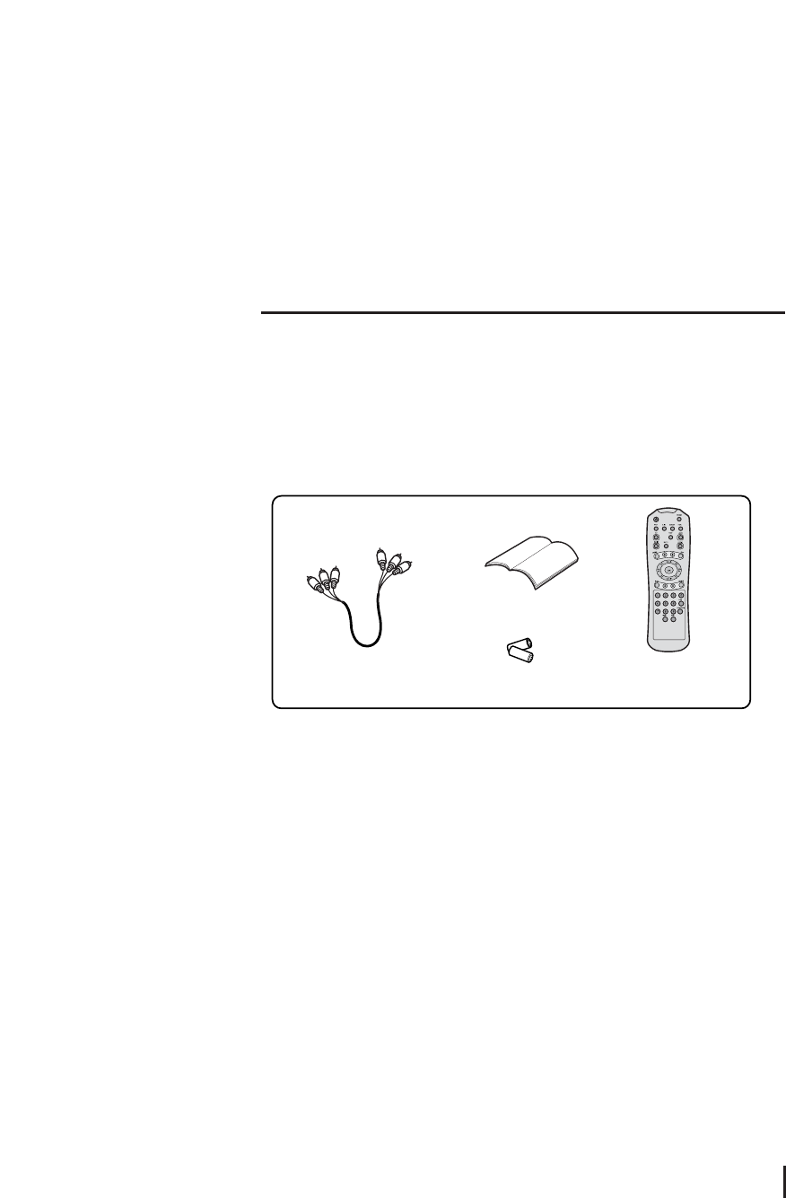
1.2 Accessories
RCA cable
User’s Guide
Battery
Remote Control Unit
RF Cable
User Guide
Remote Control Unit
Batteries (AA)
2
Accessories
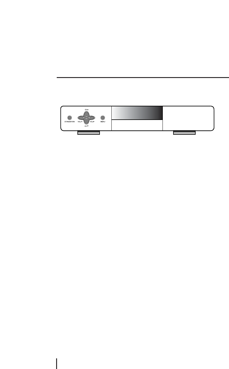
2.1 Front pannel
STANDBY ON
Turn the power on/off.
Volume ◀◀▶▶
Control volume, change item on menu or input frequency value.
Channel ▲▲▼▼
Change channel, move menu, or input frequency value.
OK
Select menu or value on menu item.
MENU
Shows the menu application.
CONTROLS AND FUNCTIONS
3
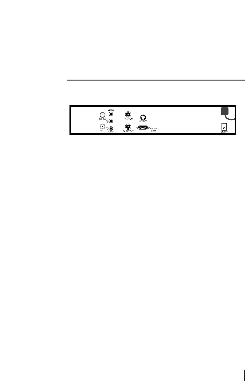
2.2 Rear pannel
DIGITAL
It receives signals from the LNB in the range of 950 ~ 2150MHz. Connect a satellite dish
to DIGITAL.
OUT
It sends signal to the another receiver.
AUDIO
It provides stereo audio output. Connect the audio on TV to AUDIO with RCA cable.
VIDEO
It provides composite video output. Connect the Video on TV to VIDEO with RCA cable.
TV ANT IN
The signal supplied to this connector from a TV antenna will be sent to TV antenna
output. Connect a TV antenna to TV ANT IN.
TV output
It provides a modulated audio and video from the receiver. Connect the TV/VCR on TV to
TV/VCR with the RF cable.
RS-232C
It receives data by connecting to PC for software upgrading. Connect with RS-232C
cable a PC and receiver.
S-VIdeo
It provides high definition screen.
ON/OFF
The switch is to turn on or off the main power of the receiver mechanically.
4
Rear pannel
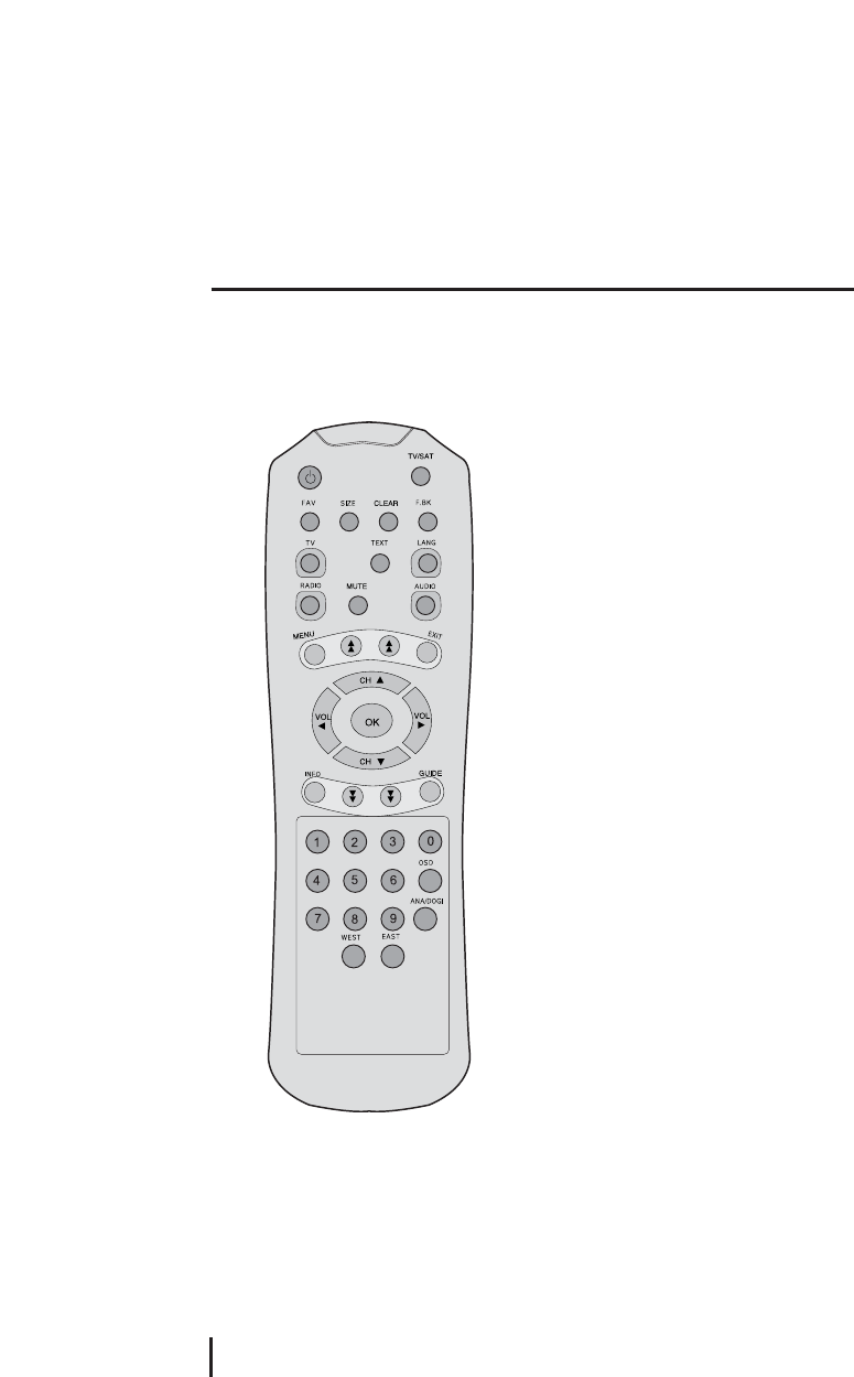
2.3 Remote Control Unit
CONTROLS AND FUNCTIONS
5
Open the controller cover on the back and insert two batteries (AA - 1.5V).
POWER
Turn the power on/off.
TV/SAT
Select between TV Channels and Satellite
channels for RF output.
FAV
Add TV or Radio channel to the favorite list
on Edit TV(Radio) Channels, or watch
favorite channel from your favorite list.
SIZE
Select between standard 4:3 and wide 16:9
screen sizes.
F. BK
It is to move to previous channel.
TV
Change to TV mode from radio channel.
TEXT
Change to Teletext mode.
LANG
Select the audio language from 2 or more
audio language channels available.
RADIO
It is for fast change to radio mode from TV channel. Shows the current Radio program list.
MUTE
Deactivate current sound.
AUDIO
Select Stereo, Main or Sub from multi language channels available.

MENU
Shows the menu application.
Page UP/DOWN
Move to previous/next page on TV(Radio), Favorite Channels or Edit TV(Radio) Channels.
EXIT
Exit from the menu.
Volume ◀◀▶▶
Control volume, change item on menu or input frequency value.
Channel ▲▲▼▼
Change channel, move menu, or input frequency value.
OK
Select menu or value on menu item.
INFO
Shows the information of current channel. Click the INFO button twice, TELETEXT mode
will be displayed.
GUIDE
Shows the broadcasting information.(Video - Audio - LNB)
Numeric(0~9)
Move menu, change channel or input frequency value.
OSD
When analog satellite signal is received, it is to turn OSD on or off.
ANA/DIGI
Change between analog mode and digital mode.
EAST/WEST
The function of EAST/WEST button is to move the Position Actuator
westward/eastward.
6
Remote Control Unit
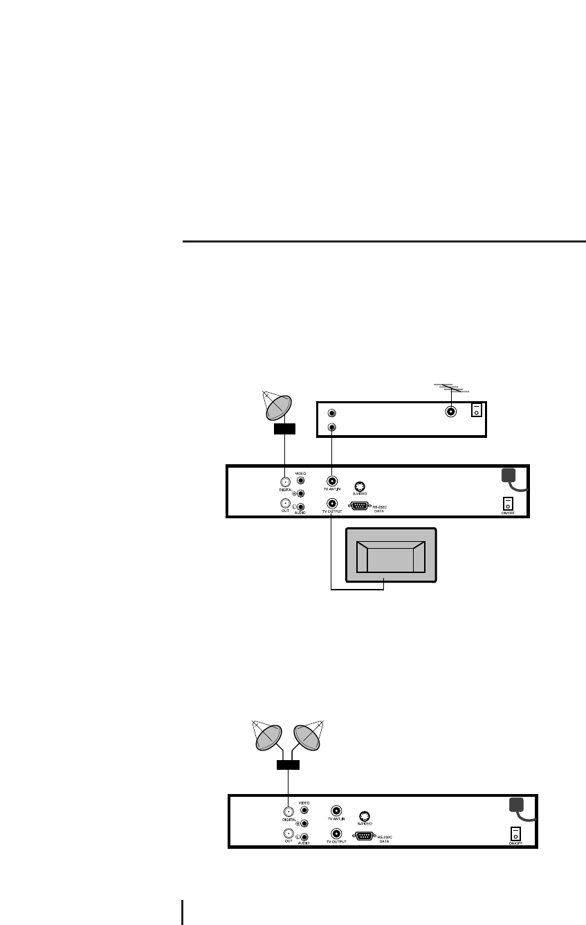
3.1 Connecting to the TV, VCR and Satellite Antenna
It is not necessary to adjust power, as the product is of free - voltage (110V )
1. Connect the RF cable from the TV OUTPUT on the satellite receiver to a TV and
connect the RF modulate on the VCR and the TV ANT.IN.
3. Connect an antenna to the LNB socket on the VCR or other receiver and cable of the
satellite dish to the DIGITAL on the satellite receiver.
3.2 Connecting DiSEqC switch
If you have one antenna equipped with many LNBs or two antennas with one LNB on
each, you need a DiSEqC switch.
1. Connect the LNBs to a DiSEqC switch at first.
2. Connect the antenna cable to the OUT connector on the DiSEqC switch and connect
the end of the cable to the DIGITAL on the satellite receiver.
Connections
7
DiSEqC switch
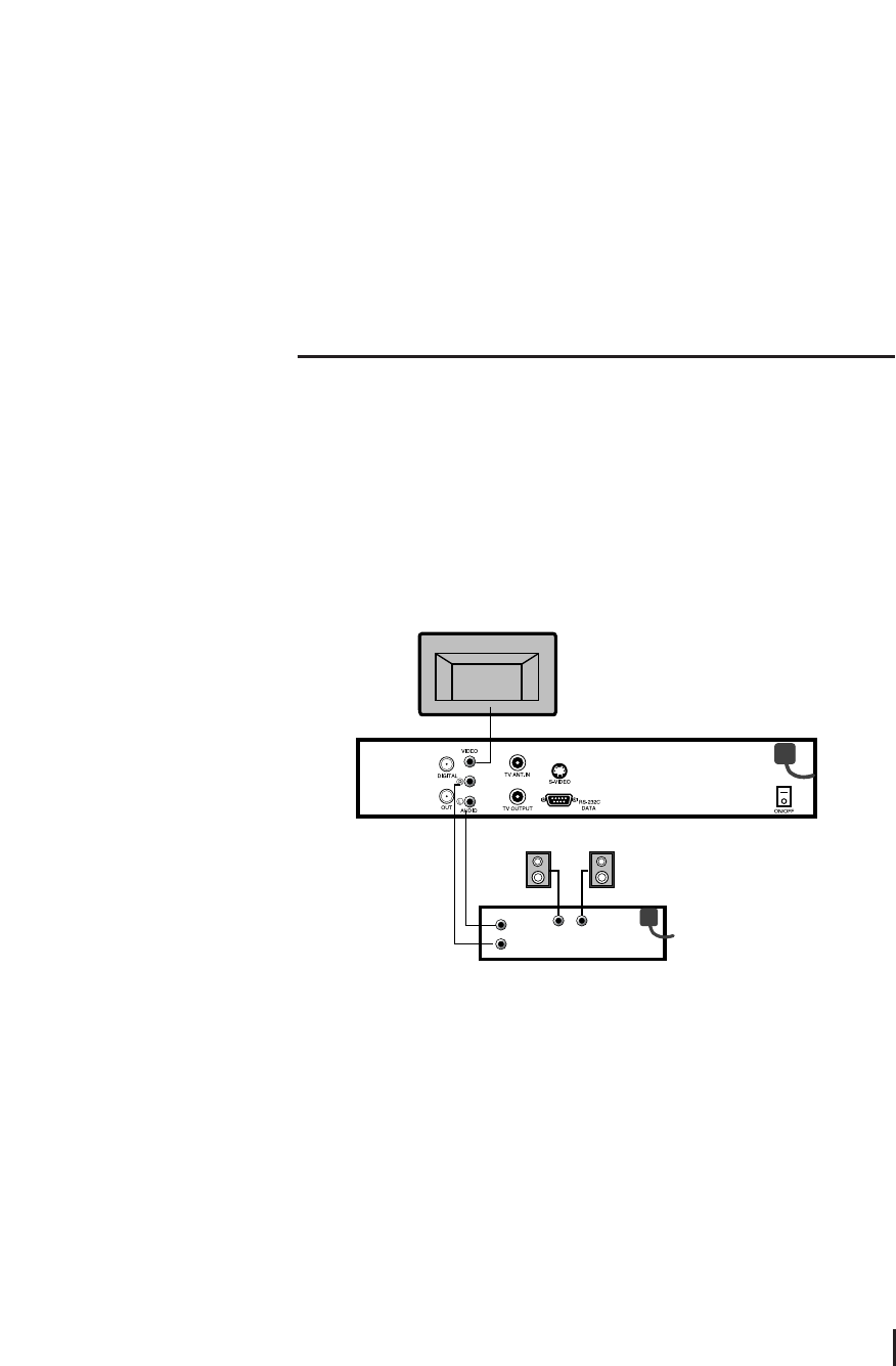
3.3 Connecting to the TV, HiFi system and 0/12V switch
1. Connect the RCA cable from the VIDEO INPUT on the TV to the VIDEO on the satellite
receiver.
2. To use 0/12V switch, connect one cable of the 0/12V switch to the 0/12V on the
satellite switch and connect another cable to the DIGITAL on the satellite receiver.
3. Connect a RCA stereo cable from the AUDIO RL on the satellite receiver to the AUDIO
RL on the HiFi system.
8
Connecting to the TV
4.1 Basic Settings
If it is the first time using a receiver, you should set parameters for system configuration.
Refer to the following section.
1. Turn on your TV and Satellite receiver.
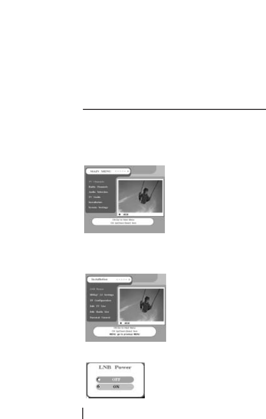
2. Press the MENU button, main menu screen will appear as shown below.
<LNB Power>
1. Select Installation on the Main Menu.
2. Select LNB Power.
3. If LNB Power is independently supplied from outside source, set the LNB Power OFF.
Otherwise set it ON.
Settings and Operations
9
4. After completion of LNB Power setting, go back to Installation menu by pressing
MENU.
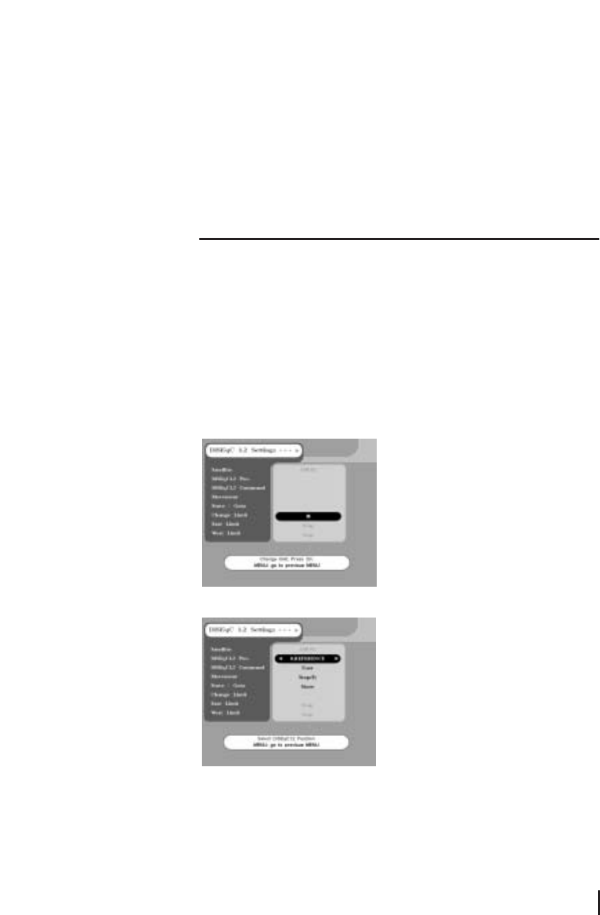
<DiSEqC 1.2 Limit Settings>
If you have a DiSEqC 1.2 motoried system to control your satellite antenna you have to
make the following setting. First, you must select ON on DiSEqC 1.2 of LNB Setting in
the TP Configuration. < ☞Please refer to the TP Configuration section >
1. Select DiSEqC 1.2 Limit Settings of the installation.
2. You should set the East Limit and West Limit of your satellite antenna If you use the
satellite receiver at first. Press OK button on the Change Limit item, set the East/West
Limit.
3. Select satellite you want and DiSEqC1.2 Pos. will be set automatically.
Satellite / DiSEqC1.2 Pos.
The Satellite shows current name of satellite, and DiSEqC1.2 Pos. shows positioner
value of the current satellite.
DiSEqC1.2 Command
DiSEqC1.2 Command changes the current mode between Installer and User.
10
DiSEqC1.2 Limit Settings
Movement
In User mode this is used to tune the position of the motor. In Installer mode this is used
to search for the position of a satellite manually.
Store
Stores the current position of the motor for the selected satellite name.
Goto
Moves the motor to the stored position of the selected satellite name.
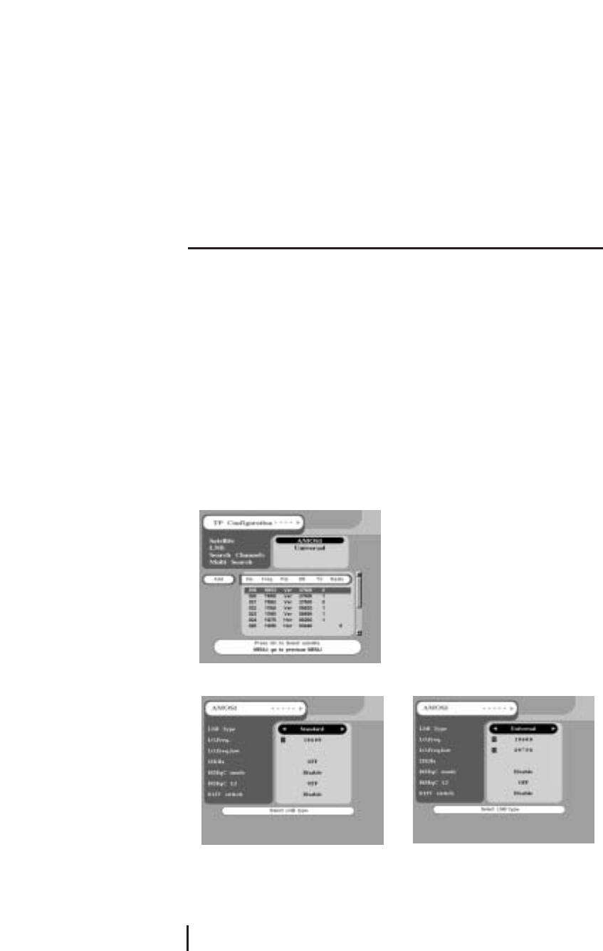
<TP Configuration>
You have to know valid value for your LNB at first.
1. Select TP Configuration of the installation.
2. Select correct name of Satellite. If there is no proper satellite name listed in the item,
select one from any of USER1 ~ USER 19.
3. To change value of LNB from each satellite, press OK button from LNB.
< Standard > < Universal >
Settings and Operations
11
4. For universal type of LNB, select Universal from LNB Type item and input the LNB
frequency value on L.O.Freq. and L.O.Freq.Low by using VOL ◀▶or numeric key.
For standard type of LNB, select Standard from LNB Type and input correct value on
L.O.Freq..
5. While only 1 antenna is in use, set the 0/12V switch and DiSEqC mode to Disable. In
case of STANDARD, select OFF from 22KHz. If more then 1 antenna is in use, select 0V
or 12V from 0/12V switch, or select a proper position from Mini A, Mini B, DiSEqC 1 ~
DiSEqC 4 by different DiSEqC type as you are using DiSEqC switch.
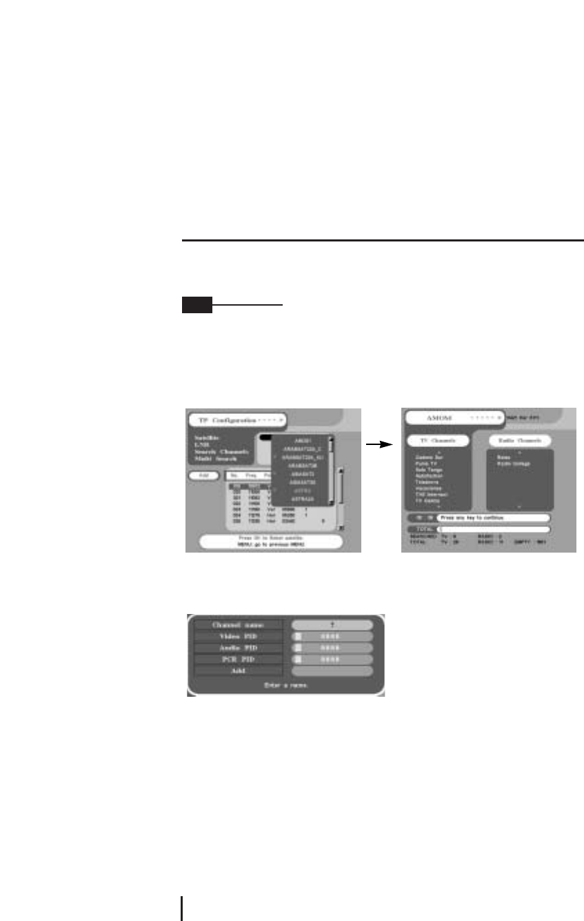
6. Select Search Channels on the TP Configuration press OK, all the available TP will be
searched automatically.
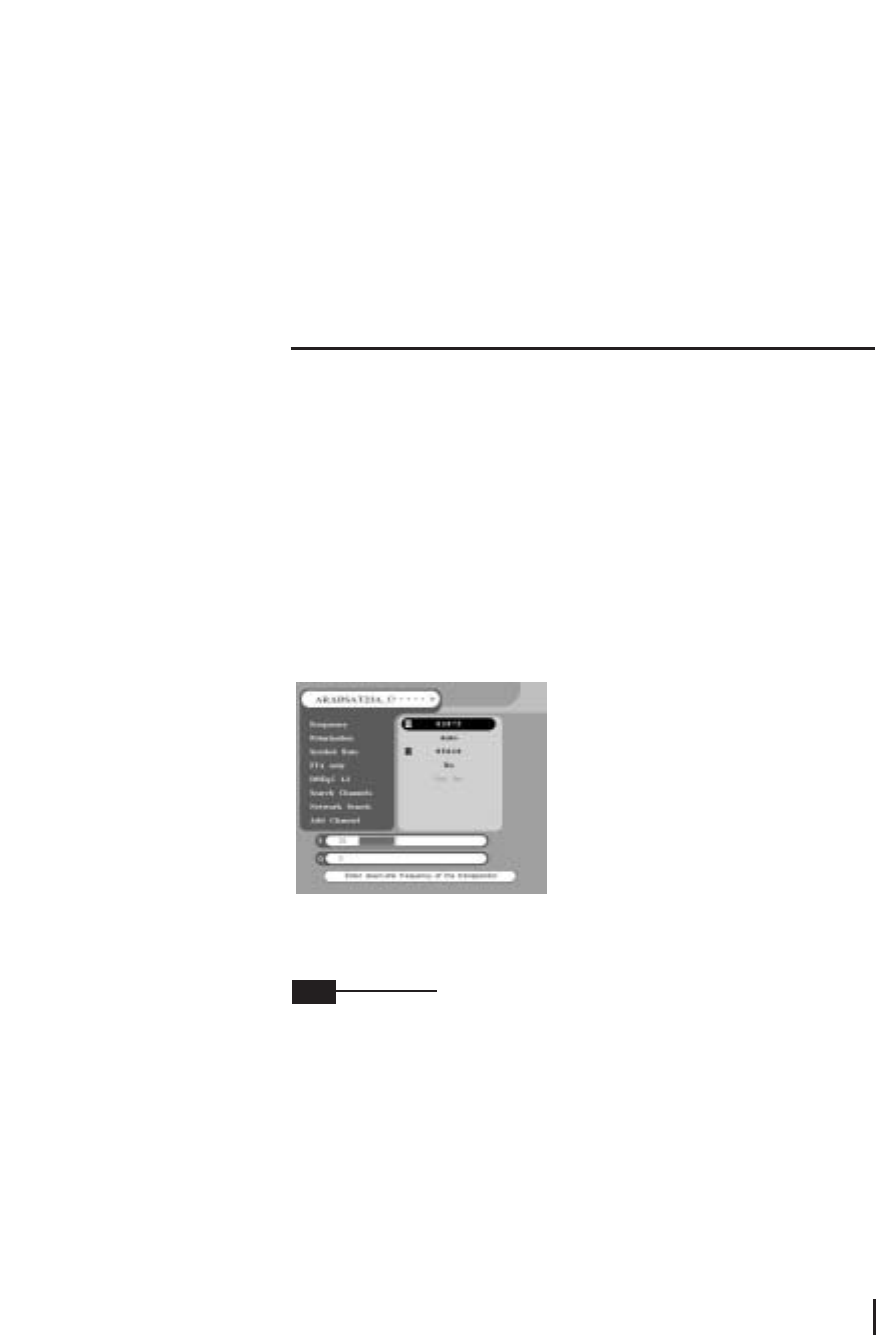
7. Move to desired TP with CH ▲▼ on the RCU. If there are no transponder data which
you want, move to Add and press OK button.
8. Select the desired satellite. And input correct values of Frequency, Polarization and
Symbol Rate. Select the Polarization value as Hor or Ver. If you did not know accurate
polarization value select Auto.
You should find the correct data from satellite magazine or internet(http://www.SATCODX.com).
9. After all the values are input, select Search Channels and wait until the automatic
search is completed.
If FTA only is selected as YES, only free channels will be searched without scrambled
pay channels. Otherwise all channel with scrambled pay channels will be searched.
Scrambled pay channels is marked as $ at the beginning of the channel name.
After successful completion of channel searching, move to TV Channels or Radio
Channels on MAIN MENU to select currently received channels. Then you should select
the TV channel or Radio channel which you want. After then you can watch the TV
program or listen to the radio.
12
TP Configuration
Note
To find not only TP information but also all the channels from current satellite, select
Network Search.
Depending on certain TP or satellite, the Network Search function may not work.
10. To use the Multi Search function, connect the DiSEqC switch or set the DiSEqC 1.2 of
Installation. You can search all the channels from the satellites which you select.
Select the satellites by FAV button, and press Multi Search.
11. In case of searching a certain satellite which can not be searched by TP Search, add
channels by PID. Select Add Channel and input proper Channel name and input the
values of Video PID, Audio PID and PCR PID. Then, press OK button from the Add item.
Settings and Operations
13
Note
4.2 Viewing TV(or Radio)
1. Press the Power button.
2. Press the TV(or Radio) button.
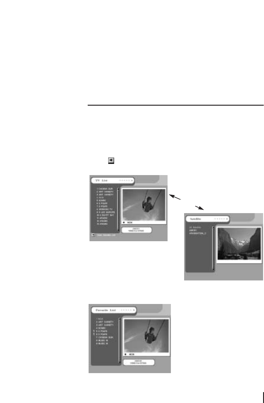
3. If you want to see all TV channel list, click the MENU button and then select the TV
Channels(or Radio Channels). TV Channels(or Radio Channels) window will appear.
Click the , you will see current Satellite name box. Select any satellite in the
satellite name box, only the TV list of selected satellite will be displayed.
Viewing Favorite Channel
1. Press FAV key.
2. Select a CH ▲▼
. To move to next or
previous page, press PAGE UP/DOWN
buttons on Favorite TV(or Radio) List.
14
Viewing TV
VOL ◀
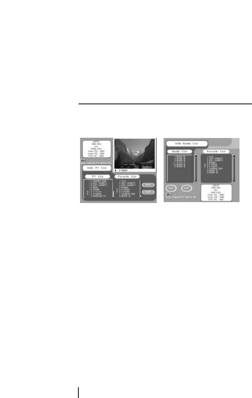
Edit TV Channels / Edit Radio Channels
From these menus you can creat and edit channel list.
Press OK button from Edit TV Channels and similar screen will be shown as below.
Arrange channel
To change the channel orders from TV List, press OK button from your desired channel.
Then you should move to desired number by pressing CH ▲▼, after then press OK
button. Its orders will be changed.
Delete channel
To delete a certain channel from current TV List, press CLEAR button on the channel to
be deleted. To confirm the deletion, press CLEAR button once more. To cancel the
deletion procedure, press FAV button.
Creat favorite channel
You can creat favorite channel list, containing the channel which you want to watch
frequently.
Press FAV button channel you want, and then selected channel will be moved to Favorite
List box. To delete the disired channel from the Favorite List, press CLEAR button.
Settings and Operations
15
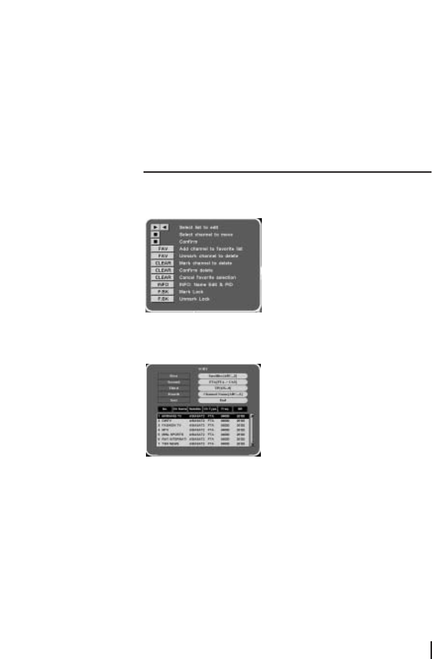
Help function
You can see the functions of each button in Edit TV List. Select the HELP button.
Sort
If you want to sort channels in order, select the SORT button in Edit channels.
You can select the order you want.
Lock Channels
From here you can lock channels in any of the lists in order to prevent your children from
watching.
If you have the password already and want to lock a certain channel, press F.BK button
at the desired channel. Everytime you watch the channel, the unit will ask you to input
password.
16
Help Function
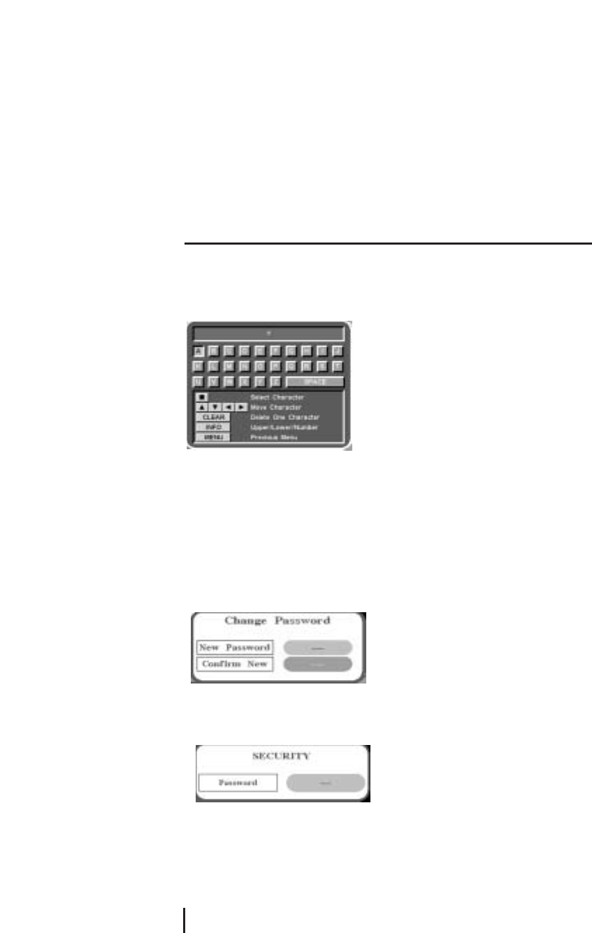
Edit Channel Name
1. Press INFO button on Edit TV or Edit Radio list. Cursor will be moved by using VOL ◀
▶, CH ▲▼.
2. Press OK button on desired alphabet. To delete pre-selected alphabet, press CLEAR button.
3. To change character set(upper, lower, number), press INFO button. By using MENU
button, it will be automatically stored and moved to previous menu.
Parental Control
If you use this funciton you have to enter the password everytime you start this satellite
receiver.
1. Select Parental Control on the installation.
2. To secure program setting and installation, select Change Password.
3. Input 4 digits New Password. And input password Confirm New once more. After all
the password function is set, the unit will ask you to input password to get into the menus
of Installation and System Settings. Input correct password which was already stored.
If the password is forgotten, contact your service provider.
Settings and Operations
17
4.3 Other functions
Audio Selection
If broadcasting channel is supporting multi language, different language can be selected from
Audio Selection.
1. To select different language on current channel, select Audio Selection on the Main Menu.
2. Press OK button on your favorite language.
According to different audio data on each channel, up to 4 different audio language types can
be selected.
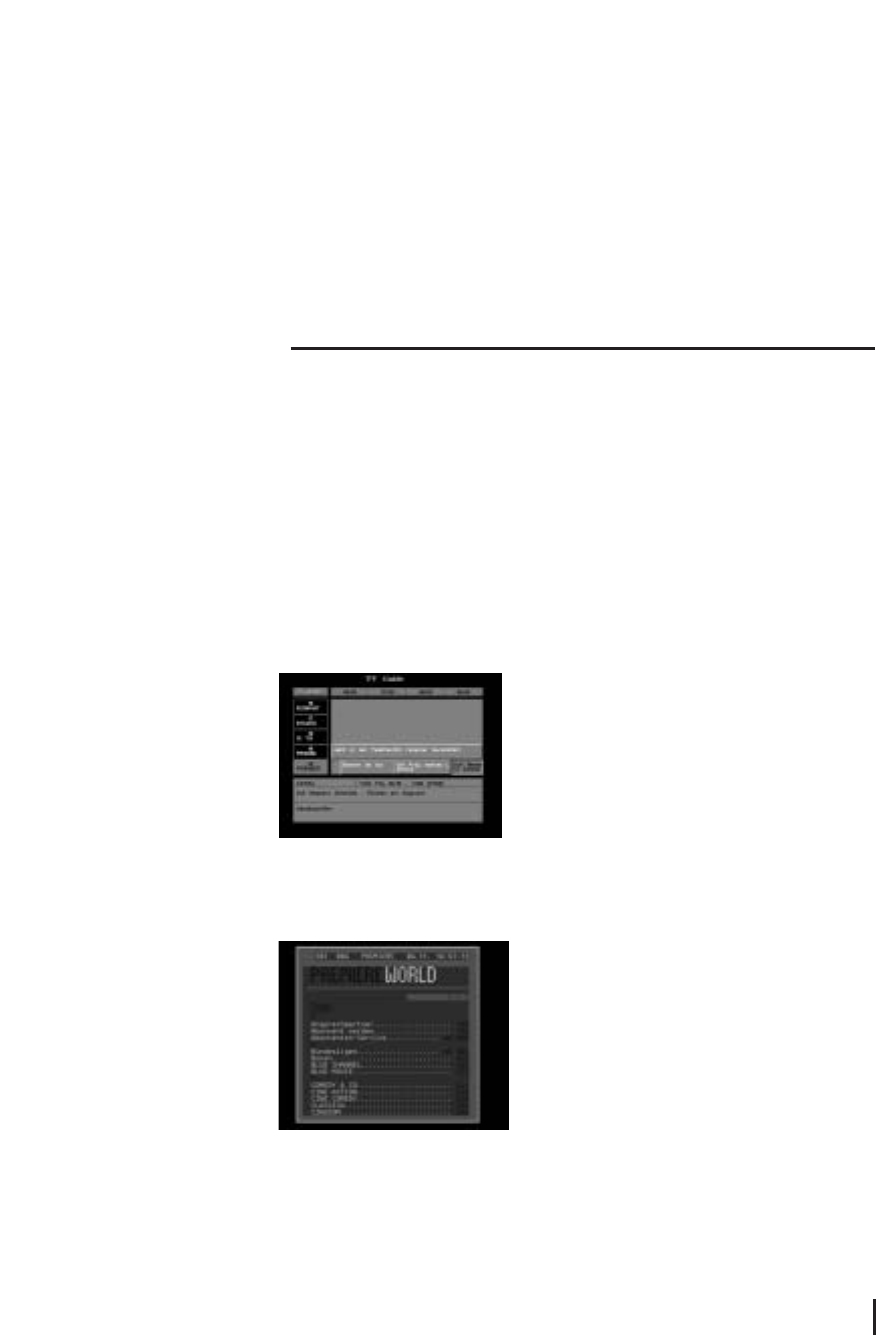
TV Guide
Press GUIDE button of RCU for channel information. This function works in digital mode only.
Teletext function
Pressing the TEXT button will open a Teletext page. Select teletext pages with the numeric
buttons on the RCU.
-From Teletext Screen
CLEAR
Overlay background screen and teletext mode according to the following order(transparency -
Teletext only - Opacity)
INFO
Hold of current Teletext page
18
Other Functions

PAGE UP/DOWN
Move previous and next page in one
CH UP/DOWN
Move previous and next page in one
FAV/TV/RADIO/F.BK/LANG/AUDIO
100/200/300/400/500/600 page level
0 ~ 9
Select Teletext page
EXIT
Exit teletext mode
Clock Function - From the Front Pannel
Menu button
The clock shows 12:00 o’clock on the front panel when the power is off. If user press
MAIN button, the 12:00 o’clock is on and off continually and then user can set up the
time using the VOL, CH, OK buttons. If user press MENU button again, the setting is
finished and the time works regularly.
Channel button
This CH ▲▼allows user to set up the time.
Volume button
This VOL ◀▶allows user to set up the minute.
OK button
This OK button allows user to finish the setup of time. If user press OK button after
setting up time, the on and off is gone on the front panel and the time works regularly.
Settings and Operations
19
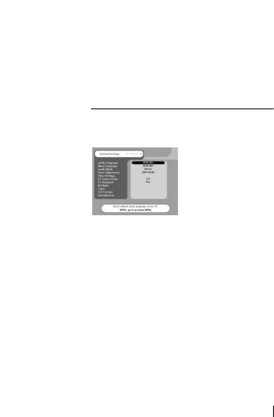
4.4 System Settings
Please make sure to press OK button always, after the changing items of System
Settings.
Audio language
Only if a current channel contains 2 or more audio language information, set the Audio
Language as English or other favorite language. Then press OK button for its
confirmation.
Menu Language
For menu language selection, select desired language from Menu Language of system
Settings.
Audio mode
Select desired audio mode among Stereo, Main or Sub. For general selection, Stereo is
recommended.
Time Adjustment
To set the receiver time for EPG(Electronic Program Guide), set the time according to
GMT(Greenwich Mean Time) by using CH ▲▼. If EPG in England is needed to
20
System Settings
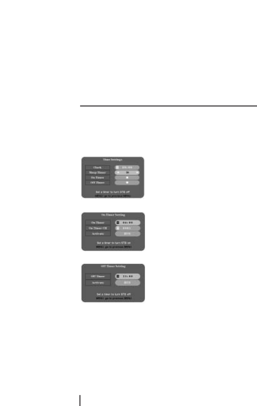
Time Settings
Use clock, sleep, on/off Timer function by choosing time settings menu.
1. Press CH(▲▼) buttons or number buttons to set the local time.
2. Set the time STB turns on with on Timer setting menu.
3. Select a channel you wish to see in running the on Timer function.
4. Set the time STB turns off with off Timer setting menu.
TV Aspect Ratio
Select 4:3 for normal TV or 16:9 for wide TV. Then press OK button for its confirmation.
If 4:3 ratio is selected on normal TV for wide channel, both left and right side of the
screen will be a bit trimmed. If 16:9 ratio is selected on normal TV for wide channels the
screen trim symptom will not occur. However the screen will be in narrow view.
Wide screen will be properly viewed, only when wide channel is broadcasting.
TV Standard
Except for a few, most countires are using PAL system for TV signal, accordingly set TV
Standard as PAL. To be more flexible for NTSC or PAL signal from different satellites,
select MULTI for automatic signal conversion. Then press OK button for its confirmation.
Settings and Operations
21
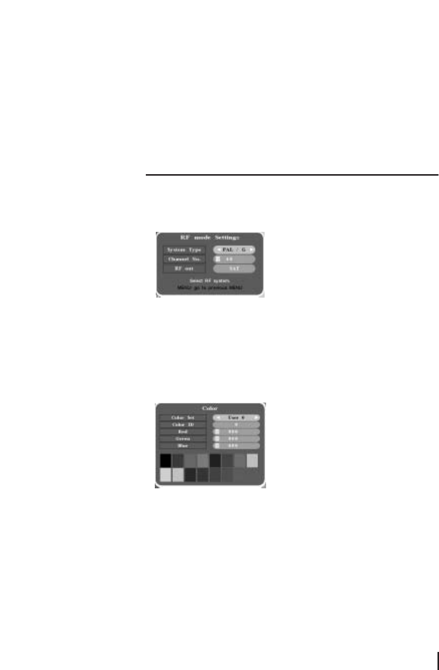
RF mode
If the satellite receiver is connected to the TV with a RF cable, you have to set the RF
mode, which is dependent on the country where the satellite is being used.
1. Select the accurate RF System type of country the satellite receiver is used.
2. Select the Channel No(Select a channel of RF output of TV set that you are using).
3. Select TV or SAT on the RF out.
Color
1. The color change from OSD display menu screen is available from 1 to 4 on Color Set.
By changing the Color set numbers, the changes in color can be easily noticed from total
different color sets.
2. To make partial changes in each section, change th Color ID and input different values
to Red, Green, and Blue. Color ID 1 ~ 7 is the color of ICON and the COlor ID 8 ~ 15 is the
colors of menu and background.
S/W Version
Show software version. Select S/W Version.
Initialization
Press OK button from Initialization. If you want initialization, select OK button,
otherwise, select any button of remote controller. The receiver will be turned off and on
automatically after 1~2 seconds to initialize all the values to factory setting mode.
As this procedure will clear and set to factory default values, end users are not
recommended to operate this function.
22
S/W Version
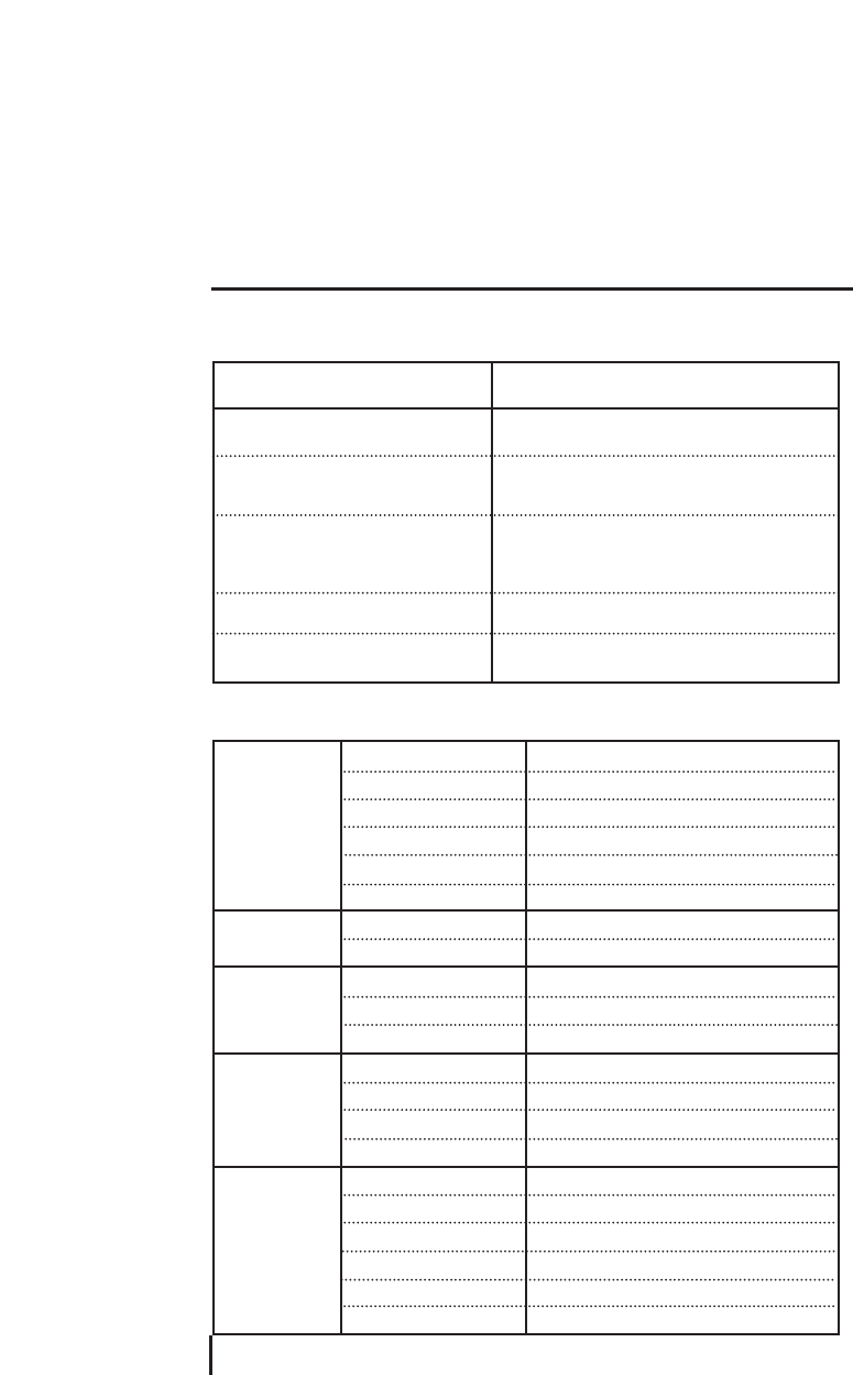
5.1 Troubleshooting
5.2 Specification
Appendix
23
SYMPTOM
No picture display and no LCD channel
display
No picture display with normal LCD
channel display
No satellite channel with MAIN MENU
screen on
No sound with normal screen display
Remote control unit does not work
LNB/Tuner
MPEG
VIDEO
Audio
General Data
RF input frequency
RF input level
LNB control
LNB power
LNB tone switch
External LNB switch
VIdeo
Audio
Resolution
Video output level
Aspect ratio
Frequency range
Sampling frequency
Frequency response
Audio output level
Supply voltage
Power consumption
Operating temp.
Storage temp.
Dimensions
Weight
950 to 2,150MHz
-65 to -25dBm
DiSEqC1.0/1.2
13V/18V(Max.400mA)
22KH±2KHz(0.6Vp-p)
0/12V(100mA)
MPEG-II Main Profile@Main Level
MPEG-II layer I&II
720×576
1Vp-p into 75Ω
4:3, 16:9
20Hz to 20KHz
32/44.1/48KHz
20Hz to 20KHz Hi-Fi Quality Digital stereo
2V rms into 600Ω
(110V AC, 50/60Hz)
Max.100W(Standby 15W)
0℃~ 50℃
-40℃~65℃
340(W)×247(D)×67.5(H)mm
3.0Kg
SOLUTION
Check the power connection
1. Check the connection with TV
2. Check the connection between TV outside input
and receiver cable
1. Check the LNB, Frequency, Polarization and
Symbol Rate from Installation menu
2. Check the connection of receiver or Antenna
angle
1. Check between sound output connector and TV
2. Check if it is not in MUTE condition
Check if the batteries in remote control unit are
dead

5.3 Glossary
LNB
Low Noise Block converter. The LNB is an electronic unit mounted on satellite dish to
receive signals reflected by the dish and convert to signals.
L.O. frequency
Local Oscillator frequency as a part of LNB. It converts the satellite frequency to usable
signals for the receiver.
Polarization
Polarization allows several programs to be fitted into same frequency band.
Symbol Rate
Size of the digital package transmission
Parental Control
The function is to allow parents to lock channels for unsuitable viewers. A locked
program can only be unlocked with the password.
DVB
Digital Video Broadcast. International standard for digital TV broadcasting
MPEG
Moving Picture Experts Group, A system for compression of digital data
RF
Radio Frequency
EPG
Electronic Programming Guide. Program information is displayed on the TV screen,
depending upon the satellite condition.
MHz
Abbreviation for MegaHertz. The prefix mega means million, and Hertz means cycles per
second.
DiSEqC
Digital Satellite Equipment Control
24
Glossary

NTSC
National Television Standards Committee
PAL
Phase Alternate Line
Ku band
11~18GHz Frequency
C band
3~4GHz Frequency
SCPC
Single Channel Per Carrier
MCPC
Multi Channel Per Carrier
PID
Packet Identifier.
TP
TransPonder
SCART, RCA
A connector for connection of Satellite receiver, VCR and TV sets.
VCR
Video Cassette Recorder.
Appendix
25