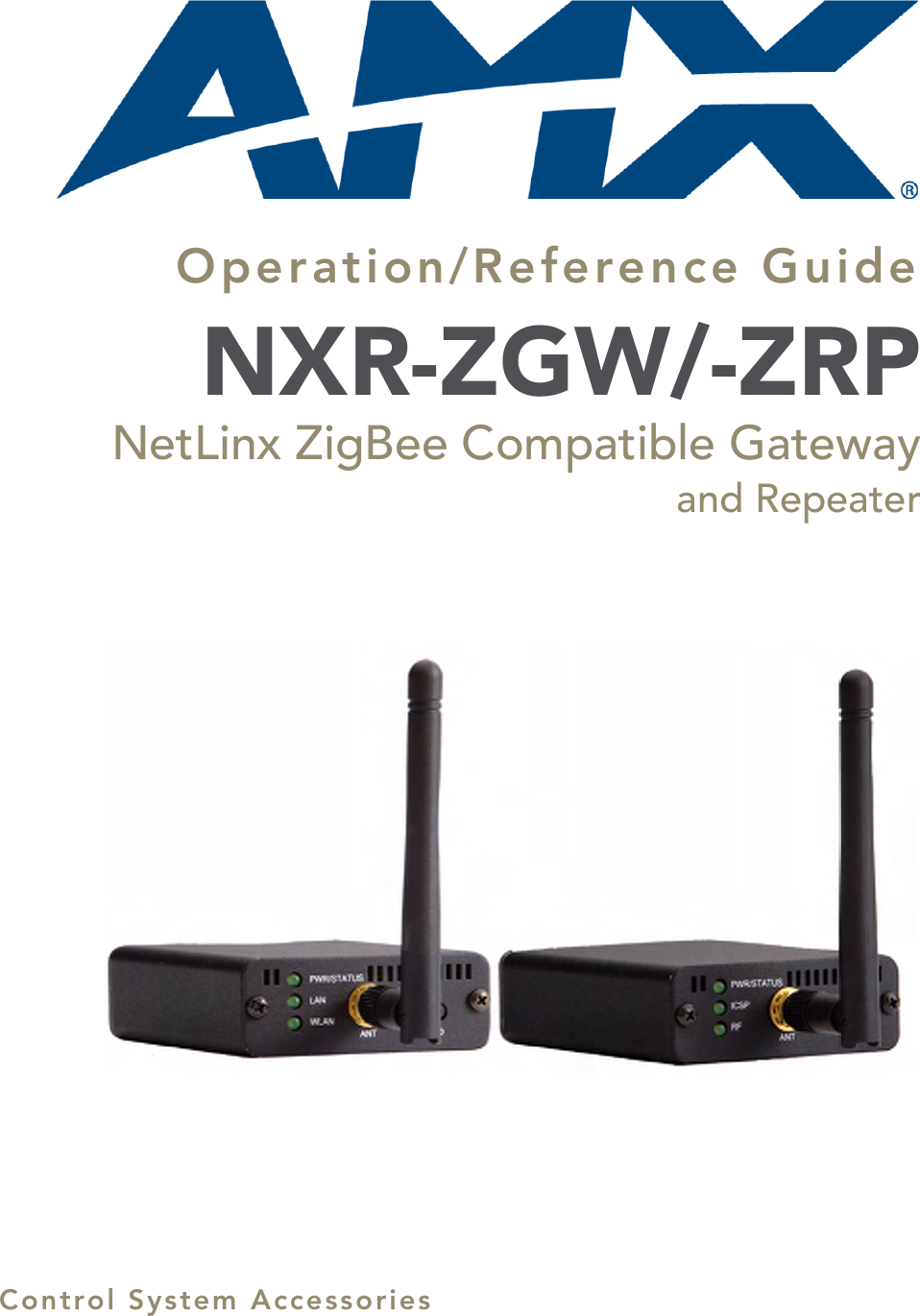
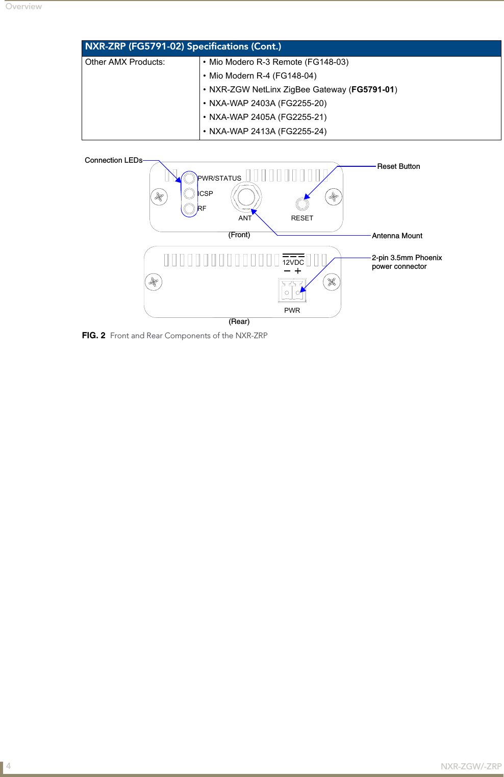
AMX NXR-ZGW NetLinx ZigBee Compatible Gatewayand Repeater User Manual Frodo

AMX LLC NetLinx ZigBee Compatible Gatewayand Repeater Frodo

Manual

Operation/Reference GuideControl System AccessoriesNXR-ZGW/-ZRPNetLinx ZigBee Compatible Gatewayand Repeater
AMX Limited Warranty and DisclaimerAMX warrants its products to be free of defects in material and workmanship under normal use for three (3) years from the date of purchase from AMX, with the following exceptions:• Electroluminescent and LCD Control Panels are warranted for three (3) years, except for the display and touch overlay components that are warranted for a period of one (1) year.• Disk drive mechanisms, pan/tilt heads, power supplies, and MX Series products are warranted for a period of one (1) year.• AMX Lighting products are guaranteed to switch on and off any load that is properly connected to our lighting products, as long as the AMX Lighting products are under warranty. AMX does guarantee the control of dimmable loads that are properly connected to our lighting products. The dimming performance or quality cannot be guaranteed due to the random combinations of dimmers, lamps and ballasts or transformers.• Unless otherwise specified, OEM and custom products are warranted for a period of one (1) year.• AMX Software is warranted for a period of ninety (90) days.• Batteries and incandescent lamps are not covered under the warranty.This warranty extends only to products purchased directly from AMX or an Authorized AMX Dealer.All products returned to AMX require a Return Material Authorization (RMA) number. The RMA number is obtained from the AMX RMA Department. The RMA number must be clearly marked on the outside of each box. The RMA is valid for a 30-day period. After the 30-day period the RMA will be cancelled. Any shipments received not consistent with the RMA, or after the RMA is cancelled, will be refused. AMX is not responsible for products returned without a valid RMA number.AMX is not liable for any damages caused by its products or for the failure of its products to perform. This includes any lost profits, lost savings, incidental damages, or consequential damages. AMX is not liable for any claim made by a third party or by an AMX Dealer for a third party.This limitation of liability applies whether damages are sought, or a claim is made, under this warranty or as a tort claim (including negligence and strict product liability), a contract claim, or any other claim. This limitation of liability cannot be waived or amended by any person. This limitation of liability will be effective even if AMX or an authorized representative of AMX has been advised of the possibility of any such damages. This limitation of liability, however, will not apply to claims for personal injury.Some states do not allow a limitation of how long an implied warranty last. Some states do not allow the limitation or exclusion of incidental or consequential damages for consumer products. In such states, the limitation or exclusion of the Limited Warranty may not apply. This Limited Warranty gives the owner specific legal rights. The owner may also have other rights that vary from state to state. The owner is advised to consult applicable state laws for full determination of rights.EXCEPT AS EXPRESSLY SET FORTH IN THIS WARRANTY, AMX MAKES NO OTHER WARRANTIES, EXPRESSED OR IMPLIED, INCLUDING ANY IMPLIED WARRANTIES OF MERCHANTABILITY OR FITNESS FOR A PARTICULAR PURPOSE. AMX EXPRESSLY DISCLAIMS ALL WARRANTIES NOT STATED IN THIS LIMITED WARRANTY. ANY IMPLIED WARRANTIES THAT MAY BE IMPOSED BY LAW ARE LIMITED TO THE TERMS OF THIS LIMITED WARRANTY.
Software License and Warranty AgreementLICENSE GRANT. AMX grants to Licensee the non-exclusive right to use the AMX Software in the manner described in this License. The AMX Software is licensed, not sold. This license does not grant Licensee the right to create derivative works of the AMX Software. The AMX Software consists of generally available programming and development software, product documentation, sample applications, tools and utilities, and miscellaneous technical information. Please refer to the README.TXT file on the compact disc or download for further information regarding the components of the AMX Software. The AMX Software is subject to restrictions on distribution described in this License Agreement. LICENSEE MAY NOT SUBLICENSE, RENT, OR LEASE THE AMX SOFTWARE. Licensee may not reverse engineer, decompile, or disassemble the AMX Software. INTELLECTUAL PROPERTY. The AMX Software is owned by AMX and is protected by United States copyright laws, patent laws, international treaty provisions, and/or state of Texas trade secret laws. Licensee may make copies of the AMX Software solely for backup or archival purposes. Licensee may not copy the written materials accompanying the AMX Software. TERMINATION. AMX RESERVES THE RIGHT, IN ITS SOLE DISCRETION, TO TERMINATE THIS LICENSE FOR ANY REASON AND UPON WRITTEN NOTICE TO LICENSEE. In the event that AMX terminates this License, the Licensee shall return or destroy all originals and copies of the AMX Software to AMX and certify in writing that all originals and copies have been returned or destroyed. PRE-RELEASE CODE. Portions of the AMX Software may, from time to time, as identified in the AMX Software, include PRE-RELEASE CODE and such code may not be at the level of performance, compatibility and functionality of the final code. The PRE-RELEASE CODE may not operate correctly and may be substantially modified prior to final release or certain features may not be generally released. AMX is not obligated to make or support any PRE-RELEASE CODE. ALL PRE-RELEASE CODE IS PROVIDED "AS IS" WITH NO WARRANTIES.LIMITED WARRANTY. AMX warrants that the AMX Software will perform substantially in accordance with the accompanying written materials for a period of ninety (90) days from the date of receipt. AMX DISCLAIMS ALL OTHER WARRANTIES, EITHER EXPRESS OR IMPLIED, INCLUDING, BUT NOT LIMITED TO IMPLIED WARRANTIES OF MERCHANTABILITY AND FITNESS FOR A PARTICULAR PURPOSE, WITH REGARD TO THE AMX SOFTWARE. THIS LIMITED WARRANTY GIVES LICENSEE SPECIFIC LEGAL RIGHTS. Any supplements or updates to the AMX SOFTWARE, including without limitation, any (if any) service packs or hot fixes provided to Licensee after the expiration of the ninety (90) day Limited Warranty period are not covered by any warranty or condition, express, implied or statutory.LICENSEE REMEDIES. AMX's entire liability and Licensee's exclusive remedy shall be repair or replacement of the AMX Software that does not meet AMX's Limited Warranty and which is returned to AMX. This Limited Warranty is void if failure of the AMX Software has resulted from accident, abuse, or misapplication. Any replacement AMX Software will be warranted for the remainder of the original warranty period or thirty (30) days, whichever is longer. Outside the United States, these remedies may not available.NO LIABILITY FOR CONSEQUENTIAL DAMAGES. IN NO EVENT SHALL AMX BE LIABLE FOR ANY DAMAGES WHATSOEVER (INCLUDING, WITHOUT LIMITATION, DAMAGES FOR LOSS OF BUSINESS PROFITS, BUSINESS INTERRUPTION, LOSS OF BUSINESS INFORMATION, OR ANY OTHER PECUNIARY LOSS) ARISING OUT OF THE USE OF OR INABILITY TO USE THIS AMX SOFTWARE, EVEN IF AMX HAS BEEN ADVISED OF THE POSSIBILITY OF SUCH DAMAGES. BECAUSE SOME STATES/COUNTRIES DO NOT ALLOW THE EXCLUSION OR LIMITATION OF LIABILITY FOR CONSEQUENTIAL OR INCIDENTAL DAMAGES, THE ABOVE LIMITATION MAY NOT APPLY TO LICENSEE.U.S. GOVERNMENT RESTRICTED RIGHTS. The AMX Software is provided with RESTRICTED RIGHTS. Use, duplication, or disclosure by the Government is subject to restrictions as set forth in subparagraph ©(1)(ii) of The Rights in Technical Data and Computer Software clause at DFARS 252.227-7013 or subparagraphs ©(1) and (2) of the Commercial Computer Software Restricted Rights at 48 CFR 52.227-19, as applicable.SOFTWARE AND OTHER MATERIALS FROM AMX.COM MAY BE SUBJECT TO EXPORT CONTROL. The United States Export Control laws prohibit the export of certain technical data and software to certain territories. No software from this Site may be downloaded or exported (i) into (or to a national or resident of) Cuba, Iraq, Libya, North Korea, Iran, Syria, or any other country to which the United States has embargoed goods; or (ii) anyone on the United States Treasury Department's list of Specially Designated Nation-als or the U.S. Commerce Department's Table of Deny Orders. AMX does not authorize the downloading or exporting of any software or technical data from this site to any jurisdiction prohibited by the United States Export Laws.This Agreement replaces and supersedes all previous AMX Software License Agreements and is governed by the laws of the State of Texas, and all disputes will be resolved in the courts in Collin County, Texas, USA. For any questions concerning this Agreement, or to contact AMX for any reason, please write: AMX, 3000 Research Drive, Richardson, TX 75082.
Table of ContentsiNXR-ZGW/-ZRPTable of ContentsOverview ............................................................................................................1NXR-ZGW Specifications........................................................................................... 1NXR-ZRP Specifications ............................................................................................ 3How ZigBee works.................................................................................................... 5Security ...........................................................................................................................  5Network structure ...........................................................................................................  5Mesh Network Arrangements................................................................................... 6Single PAN ID installations..............................................................................................  6Multiple PAN ID installations ..........................................................................................  7FCC Compliance ....................................................................................................... 7Installation ..........................................................................................................9Things to Consider Before Starting .......................................................................... 9Location and Antenna Direction......................................................................................  9Connecting the Optional Accessory Antennas ................................................................  9Determining the Power Source .......................................................................................  9Connecting the NXR-ZGW to a LAN ....................................................................... 10Connecting Power to the NXR-ZGW and NXR-ZRP ................................................ 10Preparing captive wires for the 2-pin 3.5 mm mini-Phoenix connector.........................  10Using the PSN NetLinx connector for power ................................................................  10Table top installation of the NXR-ZGW and NXR-ZRP ............................................ 10Rack mounting the NXR-ZGW and NXR-ZRP .......................................................... 10Setting up a Network  .......................................................................................11NXR-ZGW Browser-based Configuration Manager Pages  ................................13Summary of Gateway Settings................................................................................ 13Checking the firmware version......................................................................................  14Checking the ZigBee firmware version..........................................................................  14Determining the IP settings of the NXR-ZGW...............................................................  14Finding the ICSP device number of this unit .................................................................  14Determining the PAN settings of the NXR-ZGW...........................................................  14Rebooting the Configuration Manager .........................................................................  14Configuration.......................................................................................................... 15Network IP Settings ......................................................................................................  15Setting the IP Address ..................................................................................................  15Setting the DNS Address ..............................................................................................  15NetLinx Settings............................................................................................................  16Setting the ICSP connection to the Netlinx master.......................................................  16
ii NXR-ZGW/-ZRPTable of ContentsUser Settings .................................................................................................................  17Setting a new username and password .........................................................................  17Personal Area Network (PAN)................................................................................. 18Network ........................................................................................................................  18Enabling and disabling the wireless network ................................................................  18Setting the PAN channel ...............................................................................................  18Security .........................................................................................................................  19Access List ..................................................................................................................... 19Connections...................................................................................................................  20Finding a device’s EUI address ......................................................................................  21Finding the device’s description....................................................................................  21Determining the device type.........................................................................................  21Finding the amount of time a signal takes from the device to the gateway and back ..  21Determining the device link quality...............................................................................  21Checking the device link status .....................................................................................  21PAN Device Details .......................................................................................................  22Putting a device on the Access List ...............................................................................  23Removing a device from the Access List .......................................................................  23Locating the device .......................................................................................................  23Changing a Connected Device description....................................................................  23Changing a device’s ZigBee networking information ....................................................  23Utilities.................................................................................................................... 25Device Firmware............................................................................................................  25Allowing firmware updates to individual devices ..........................................................  25Allowing firmware updates to all devices on a network................................................  26Connection Log .............................................................................................................  26Determining the connection status of a device .............................................................  27Finding the device’s ICSP number.................................................................................  27Traffic Log ..................................................................................................................... 28Finding the device traffic ..............................................................................................  29Device Configuration ........................................................................................31Sending Firmware to The NXR-ZGW ...................................................................... 31Before beginning the Upgrade process ........................................................................  31Upgrading The NXR-ZGW via An IP Address .......................................................... 32Preparing the Master for communication via an IP........................................................  32Verifying and Upgrading the device firmware via an IP ................................................  33Using the ID Button to Change the NXR-ZGW’s Device Number ........................... 34
Overview1NXR-ZGW/-ZRPOverviewThe NXR-ZGW (FG5791-01) is an Ethernet to ZigBee wireless gateway. The NXR-ZGW features a 10/100 Ethernet port capable of Power over Ethernet (PoE), 16 Mbytes of Flash, 16 Mbytes of SDRAM, and a ZigBee module, and is controlled via a web server interface. The NXR-ZRP (FG5791-02) is a ZigBee wireless repeater that features 16 Mbytes of Flash, 16 Mbytes of SDRAM, and a ZigBee module.NXR-ZGW SpecificationsThe following table outlines the specifications for the NXR-ZGW.    NXR-ZGW (FG5791-01) SpecificationsDimensions (HWD): • .906 x 2.500 x 3.424 (23.01 mm x 63.50 mm x 86.96 mm), depth does not include antennaWeight: • 0.35 lbs (158.75g)Power: 10.5 - 18 VDC; 13.5 (nominal operation voltage), orPower over Ethernet (PoE)Memory: • 16 Mbytes of Flash• 16 Mbytes of SDRAMRadio Specifications:Frequency IEEE 802.15.4Operating channels • 11 - 26Data Rate • 250 kbps (@2.4 GHz)Modulation technique •DSSSecurity • EUI Address filteringOutput power • Country-specific:  may be set from 0 dbm to 20 dbmCoverage area 50m typical (5-500m based on environment)Firmware/Software  Specifications:Management • Built-in browser-based management with User Name/Password authenticationIP configuration • Static IP or DHCP client (default is static, 192.168.1.140)Communications • The NXR-ZGW communicates with a Netlinx master over TCP/IP encapsulating the ICSP protocol via a physical Ethernet connection. The ICSP device number can be set via the browser-based management system.Front Components:LEDs •PWR/STATUS - A green LED that blinks to indicate the device is installed and communicating properly. Power ON, but no master connection, is indicated with a solid light; Power OFF is indicated with no light.•LAN - A green LED indicates an Ethernet connection is established. The LED blinks to indicate both sending and receiving information via Ethernet.•RF - The LED is solid when end devices are connected; end devices not connected is indicated with no LED light; the LED blinks to indicate activity.Antenna Mount A reverse SMA connection that supports a 2.4GHz antenna.ID Button When used in conjunction with NetLinx Studio, sets the device and system numbers for the NXR-ZGW. Press and hold for approximately 30 seconds to return the NXR-ZGW to factory default settings.
Overview2NXR-ZGW/-ZRPNXR-ZGW (FG5791-01) Specifications (Cont.)Rear Components:Power connector Two power options are available:• 2-pin 3.5mm Phoenix connector• Power Over Ethernet (PoE) - powers the device through the CAT5 cable. Both Power and Data can be transmitted simultaneous through the CAT5 cable when using the appropriate equipment. Ethernet port 10/100M (RJ-45) connector - used to connect the NXR-ZGW to your LAN and/or to connect your third party device to the LAN when the NXR-ZGW is used as a gateway. Certifications: • FCC ID: CWU-ZGW• IC ID: 5078A-ZGW•CE• IEC-60950Operating/Storage Environments:• Operating Temperature: -30°C (-22°F) to 70°C (158°F)• Relative Humidity: 5% to 85% non-condensing; intended for indoor use onlyIncluded Accessories: • 2.4GHZ, MONO, RSMA, 3.5IN, 2.0DBI Antenna (70-0012-SA)• Rubber feet• Velcro mounting stripOther AMX Products: • Mio Modero R-3 Remote (FG148-03)• Mio Modero R-4 Remote (FG148-04)• NXR-ZRP NetLinx ZigBee Repeater (FG5791-02)• NXA-WAP 2403A (FG2255-20)• NXA-WAP 2405A (FG2255-21)• NXA-WAP 2413A (FG2255-24)FIG. 1  Front and Rear Components of the NXR-ZGWPoE PWR12VDCETHERNETPWR/STATUSLANRFANT ID(Front)(Rear)ID ButtonAntenna Mount2-pin 3.5mm Phoenix10/100M(RJ-45) connectorConnection LEDspower connector
Overview3NXR-ZGW/-ZRPNXR-ZRP SpecificationsThe following table outlines the specifications for the NXR-ZRP.    NXR-ZRP (FG5791-02) SpecificationsDimensions (HWD): • 906 x 2.500 x 3.424 (23.01 mm x 63.50 mm x 86.96 mm) depth does not include antennaWeight: • 0.25 lbs (113.39g)Power: 10.5 - 18 VDC; 13.5 (nominal operation voltage)Memory: • 16 Mbytes of Flash• 16 Mbytes of SDRAMRadio Specifications:Frequency IEEE 802.15.4Operating channels • 11 - 26Data Rate • 250 kbps (@2.4 GHz)Modulation technique •DSSSecurity • EUI Address filteringOutput power • Country-specific:  may be set from 0 dbm to 20 dbmCoverage area 50m typical (5-500m based on environment)Firmware/Software  Specifications:Communications The NXR-ZRP communicates with a Netlinx master via a NXR-ZGW. The NXR-ZGW communicates with a Netlinx master over TCP/IP encapsulating the ICSP protocol via a physical Ethernet connection. The ICSP device number can be set via the browser-based management system.Front Components:LEDs •PWR/STATUS - A green LED that blinks to indicate the device is programmed and communicating properly. Power ON, but no master connection, is indicated with a solid light; Power OFF is indicated with no light.•ICSP - The LED is solid when ICSP connection is in place with the NetLinx master.•RF - The LED is solid when end devices are connected; end devices not connected is indicated with no LED light; the LED blinks to indicate activity.Antenna Mount A reverse SMA connection that supports a 2.4GHz antenna.Reset Button Press and hold for approximately 30 seconds to return the NXR-ZRP to factory default settings.Rear Components:Power connector • 2-pin 3.5mm Phoenix connectorCertifications: • FCC ID: CWU-ZRD• IC ID: 5088A-ZRD•CE• IEC-60590Operating/Storage Environments:• Operating Temperature: -30°C (-22°F) to 70°C (158°F)• Relative Humidity: 5% to 85% non-condensing; intended for indoor use onlyIncluded Accessories: • 2.4GHZ, MONO, RSMA, 3.5IN, 2.0DBI Antenna (70-0012-SA)• Rubber feet• Velcro mounting strip
Overview4NXR-ZGW/-ZRPNXR-ZRP (FG5791-02) Specifications (Cont.)Other AMX Products: • Mio Modero R-3 Remote (FG148-03)• Mio Modern R-4 (FG148-04)• NXR-ZGW NetLinx ZigBee Gateway (FG5791-01)• NXA-WAP 2403A (FG2255-20)• NXA-WAP 2405A (FG2255-21)• NXA-WAP 2413A (FG2255-24)FIG. 2  Front and Rear Components of the NXR-ZRPPWR12VDCRESETANTRFICSPPWR/STATUS(Front)(Rear)Reset ButtonAntenna Mount2-pin 3.5mm PhoenixConnection LEDspower connector
Overview5NXR-ZGW/-ZRPHow ZigBee worksThe NXR-ZGW, acting as a gateway, allows ZigBee-enabled devices to communicate both to and from an ICSP master. A device connects to the NXR-ZGW and is then represented to the master as an ICSP device. The master then communicates to the device through ICSP messages via a translation step at the NXR-ZGW level.The master sends "heartbeat" queries to the NXR-ZGW device; which the NXR-ZGW provides the master with a response for all devices on the ZigBee network that have an ICSP address and use ZigBee as their primary interface to the master. The response provided by the NXR-ZGW is based on the last known status of the ZigBee-enabled device. If the NXR-ZGW determines it is no longer in communication with a device, it will indicate to the master the device is non-responsive or has left the network.SecurityThe NXR-ZGW device provides two levels of security, Security Level 0 and Security Level 5. Security Level 0 provides no security and no encryption, Security Level 5 provides 32-bit Message Integrity Code (MIC).  The NXR-ZGW can be configured to permit both Security Level 0 and Security Level 5 devices or only Security Level 5 devices into the network. When enabled, security is network wide.The NXR-ZGW can also allow or deny devices to join the network based on the device’s 64-bit extended unique identifier (EUI-64) via a EUI-64 filter. The EUI-64 filter is a list of devices allowed on the network. When enabled, the EUI-64 number must be on the list for the device to enter the network. After enabling the filter, any device not on the list is instructed to leave the network.Network structureThe ZigBee network is a Personal Area Network (PAN) consisting of 1 gateway, optionally 1 or more repeaters, and end devices.A gateway initiates a ZigBee network and all devices linked to the PAN gateway do so through either direct links or through repeaters. It is the job of the gateway to establish the network’s parameters, e.g., channel and PAN ID. Within each PAN, a gateway or repeater can have 20 end devices and 4 repeaters. Each connection supports a depth of 5 devices. The topology information is contained in the system Web page.Repeaters like the NXR-ZRP are used to expand the coverage of gateway NXR-ZGWs. Every device in the PAN has a parent, and repeaters can have children. Adding repeater devices to a network can reduce the number of hops an end device needs to make to reach the gateway while extending the coverage area for the entire network. Any device attached to a repeater NXR-ZRP appears attached to the gateway NXR-ZGW in the system web page.Devices will always connect to a repeater or gateway with the least depth and then best quality. End devices cannot have children. The use of the NXR-ZGW and NXR-ZRP’s allow ZigBee-type devices to roam seamlessly from repeater to repeater within the same PAN ID.Mobile end devices tend to sleep frequently and thus enter and leave the network regularly. Upon awakening, the end device may be in a new physical location or the network may have changed channels. The end device will seamlessly search for a new parent and scan channels upon awakening.
Overview6NXR-ZGW/-ZRPMesh Network ArrangementsThe following installations depend upon the criteria for the network. A home installation would perhaps only need one NXR-ZGW or PAN ID where a commercial installation might require a NXR-ZGW and several NXR-ZRPs with a unique PAN ID for each. Further, while encryption enabling is always a good idea, it might be absolute for installation with public exposure.Single PAN ID installationsAfter you have installed the NXR-ZGW, you should consider the arrangement of devices. The following is an example where there is only one NXR-ZGW in the installation and thus only one PAN ID with which to contend. While there is no reason to worry about the wrong device appearing on the PAN ID, setting up proper security measures is a good thing. See Setting up a Network section on page 23 for setting the PAN ID and adding device EUI Addresses. When adding a ZigBee network to a NetLinx master, an Ethernet switch or hub must be added to the master for proper function of the ZigBee network.FIG. 3  Single PAN ID NetworkCAT5 EthernetconnectionNXR-ZGW(Coordinator)1 hopNetLinx MasterMio R-4
Overview7NXR-ZGW/-ZRPMultiple PAN ID installationsA more commercial application of the NXR-ZGW is having multiple gateways and specific devices operating in close proximity of each other. End devices and repeaters of different networks can operate side-by-side without interference if they have different PAN ID numbers. See Setting up a Network section on page 23 for setting the PAN ID and adding device EUI Addresses. FCC ComplianceThis device complies with Part 15 of the FCC rules. Subject to the following two conditions:1. This device must not cause harmful interference and 2. This device must accept all interference, including interference that interferes with the operation of this device. Modifications not expressly approved by the manufacturer will void the user’s authority to operate the equipment.FIG. 4  Multiple PAN ID NetworkCAT5 EthernetconnectionNXR-ZGW(Coordinator)2 hops1 hopPAN ID  1PAN ID 2NXR-ZGW(Coordinator)1 hopNXR-ZRP(Router)NetLinx MasterNXR-ZRP(Router)3 hopsNetLinx MasterCAT5 EthernetconnectionMio R-4Mio R-4 Mio R-4 Mio R-4Mio R-4Mio R-4 Mio R-4 Mio R-4This device has been evaluated and found to be compliant with the FCC Rules for RF Exposure when the device is operated at a minimum separation distance of 20 cm. from the user and nearby persons. Operation of this device at closer distances should be avoided.
Overview8NXR-ZGW/-ZRP
Installation9NXR-ZGW/-ZRPInstallationThings to Consider Before StartingSeveral factors will help decide the best place to install NXR-ZGW and NXR-ZRP devices. Before installing, consider the following:Location and Antenna DirectionThe best location for NXR-ZGW and NXR-ZRP devices are usually in the center of your wireless network, with line of sight to all of your mobile devices. Try to place the antenna in a position that can best cover your wireless network. Normally, the higher you place the antenna, the better performance you receive.Connecting the Optional Accessory AntennasSeveral accessory 2.4GHz antennas are available for use with NXR-ZGW and NXR-ZRP devices. Each of these antennas is uniquely suited to meet a wide variety of installation requirements.Determining the Power SourceBased upon location and the availability of electricity, select one of the two following methods for power: 2-pin 3.5mm Phoenix connector - Prepare the captive wire pair and insert it into the Phoenix connector. See Preparing captive wires for the 2-pin 3.5 mm mini-Phoenix connector section on page 10. This is the only power option for the NXR-ZRP device. Power Over Ethernet (PoE) - If no electrical outlet is available, you can plug one end of the CAT5 Ethernet cable into the RJ-45 jack of the NXR-ZGW and plug the other end of the CAT5 cable into a PoE supply equipment (this unit must be 802.3af compliant). The ability to choose a power supply option increases the availability of deployment locations. In addition, the NXR-ZGW makes installation into areas previously without power much easier, since it is no longer necessary to run new electrical wires to the device.
Installation10 NXR-ZGW/-ZRPConnecting the NXR-ZGW to a LANInsert one end of the CAT5 Ethernet cable into the rear RJ-45 jack (illustrated in FIG. 1) and connect the other end of the same cable to a master. See Mesh Network Arrangements section on page 6 for possible network configurations.Connecting Power to the NXR-ZGW and NXR-ZRPThe NXR-ZGW receives power via either PoE or 2-pin 3.5 mm mini-Phoenix connection, the NXR-ZRP only utilizes the 2-pin 3.5 mm mini-Phoenix connection.If PoE is selected, the NXR-ZGW will draw power through the CAT5 Ethernet cable.If the 2-pin 3.5 mm mini-Phoenix is selected, the following steps are necessary:Preparing captive wires for the 2-pin 3.5 mm mini-Phoenix connectorYou will need a wire stripper and flat-blade screwdriver to prepare and connect the captive wires.1. Strip 0.25 inch (6.35 mm) of wire insulation off all wires.2. Insert each wire into the appropriate opening on the connector according to the wiring diagrams and connector types described in this section.3. Turn the screws clockwise to secure the wires in the connector. Do not over-torque the screws; doing so can bend the seating pins and damage the connector.Using the PSN NetLinx connector for powerThe PWR and GND cable from the 12 VDC power supply must be connected to the corresponding location on the 2-pin 3.5 mm mini-Phoenix connector (FIG. 5).    1. Insert the PWR and GND wires on the terminal end of a PSN 2-pin 3.5 mm mini-Phoenix cable. Match the wiring locations of the +/- on both the power supply and the terminal connector.2. Tighten the clamp to secure the two wires. Do not over-torque the screws; doing so may strip the threads and damage the connector.3. Verify the connection of the 2-pin 3.5 mm mini-Phoenix to the power supply.Table top installation of the NXR-ZGW and NXR-ZRPUsing the provided rubber pads, place one in each bottom corner of the device.Rack mounting the NXR-ZGW and NXR-ZRPUsing the Velcro pad provided, remove the backing and adhere one side to the device. Remove the backing of the other side of the Velcro and place it on your rack where you want the NXR-ZGW/ZRP mounted.Before continuing, consult Setting up a Network section on page 23.FIG. 5  12 VDC Power Connector Wiring DiagramPWR +GND -To the Device12 VDC Power Supply
Setting up a Network11NXR-ZGW/-ZRPSetting up a NetworkAfter you have established the location of the gateway (page 9), connected it (page 10), provided power (page 10), and placed the device in either a rack(page 10) or wall installation (page 10) you can then begin configuring the NXR-ZGW and adding an NXR-ZRP and ZigBee-compatible devices to the network.1. Confirm the NXR-ZGW is receiving power by checking the PWR LED (See “Front and Rear Components of the NXR-ZGW” on page 2.).2. Using a PC connected to your NetLinx system, navigate to the NXR-ZGW Browser-based Configuration Manager (See “NXR-ZGW Browser-based Configuration Manager Pages” on page 13.) in your preferred browser application. The default IP address for the NXR-ZGW is 192.168.1.140.3. Go to the NetLinx setup page and configure the NXR-ZGW to communicate with the master.4. Go to the NXR-ZGW Browser-based Configuration Manager PAN page (See “Personal Area Network (PAN)” on page 18.) and change the PAN ID.5. Turn on AMX ZigBee-compatible devices one at a time, e.g., Mio R-4 or NXR-ZRP. Select the correct new PAN ID.6. For devices that do not have displays (NXR-ZRP), or not enough display to select the PAN ID to join a network, place each device one at a time near the gateway, turn one of them on, and configure it using the gateway web pages before turning on the next one. Then use the PAN pages to change the devices over to a new PAN ID.7. This method may also be used if you do not want to go to each ZigBee compatible device to set the PAN ID; however, once each device is set, the change must be done to the gateway itself. It may be necessary to cycle power on each device for them to come online.8. Due to the wireless nature of the ZigBee network, temporary interference (such as leaving a room or large objects passing between a remote and its gateway device) may prevent a command from reaching the NetLinx master. Therefore, programmers should consider setting safeguards for volume control, either established volume limits or timeouts with the NetLinx master or more interactive adjustment from the remote (i.e., direct volume control), to prevent issues with lost commands.If this happens while increasing volume, the master may receive the command to increase the volume but not the command to stop increasing it.
Setting up a Network12 NXR-ZGW/-ZRP
NXR-ZGW Browser-based Configuration Manager Pages13NXR-ZGW/-ZRPNXR-ZGW Browser-based Configuration Manager PagesTo access the Configuration Manager pages, enter the IP address of the NXR-ZGW into your web browser; the default IP address for the NXR-ZGW is 192.168.1.140. When prompted, enter your username and password in the spaces provided.Summary of Gateway SettingsThe Summary of Gateway Settings page is the initial access point for the user.  Upon accessing the Configuration Manager, the user must enter a username and password. The default entries are “Admin” and “1988”; changing the password as soon as possible is highly recommended.FIG. 6  Summary PageSummary PageFirmware The version of the software running on the device.ZigBee Firmware The version of software running on the ZigBee processorZigBee Stack The main version of software running on the ZigBee processorIP The IP address of the unitHost The hostname of the unit.IP Address The IP address of the unit.Subnet Mask The subnet mask associated with IP addressingGateway The IP gateway used by this unit.Device ID The ICSP device number of this unitWireless The state (Disabled/Enabled) of the wireless connection.Channel The channel the ZigBee wireless will use.
NXR-ZGW Browser-based Configuration Manager Pages14 NXR-ZGW/-ZRPChecking the firmware versionThe firmware version is listed on the Summary of Gateway Settings page of the NXR-ZGW Browser-based Configuration Manager.Checking the ZigBee firmware versionThe ZigBee firmware version is listed on the Summary of Gateway Settings page of the NXR-ZGW Browser-based Configuration Manager.Determining the IP settings of the NXR-ZGW1. Browse to the Summary of Gateway Settings page of the NXR-ZGW Browser-based Configuration Manager.2. The IP settings are listed in the aptly-named section IP Settings.Finding the ICSP device number of this unit1. Browse to the Summary of Gateway Settings page of the NXR-ZGW Browser-based Configuration Manager.2. The ICSP device number is listed under the section System Connection, Device ID.Determining the PAN settings of the NXR-ZGW1. Browse to the Summary of Gateway Settings page of the NXR-ZGW Browser-based Configuration Manager.2. The PAN settings are listed in the aptly-named section PAN Settings.Rebooting the Configuration Manager1. Browse to the Summary of Gateway Settings page of the NXR-ZGW Browser-based Configuration Manager.2. Click the Reboot button on the left bottom of the Summary of Gateway Settings page.Summary Page (Cont.)Pan ID The ZigBee personal area network ID used.Security The current state of wireless security (Disabled/Enabled).Access List The current state of the Access List (Disabled/Enabled). Distribute Password Current mode of ZigBee password distribution (Disabled/Enabled).
NXR-ZGW Browser-based Configuration Manager Pages15NXR-ZGW/-ZRPConfigurationNetwork IP SettingsThe Network IP Settings page is used to set IP and DNS addresses. The IP address can be either a static or dynamic assignment.    The DNS Address allows the IP addresses of domain name servers to be specified.Setting the IP Address1. In the menu at the top of the NXR-ZGW Browser-based Configuration Manager, select IP Settings under the section Configuration.2. Click the radio button for either Dynamic or Static. If you selected Dynamic, the DHCP server automatically provides the IP address.3. If configured for Static, type the IP address in the field provided.4. If necessary, type the subnet mask and gateway in the fields provided.5. Click Accept. 6. In the The system will need to reboot for changes to take effect window, click OK.Setting the DNS Address1. In the menu at the top of the NXR-ZGW Browser-based Configuration Manager, select IP Settings under the section Configuration. 2. Click the Static radio button in the IP Address section.FIG. 7  IP Settings PageIP AddressIP • Dynamic: IP address and subnet mask are requested from the DHCP server.• Static: User provides IP address information.Host The hostname of the unit.IP Address The IP address of the unit.Subnet Mask The IP subnet mask of the unit.Gateway The gateway used for IP routing.DNS AddressDomain Suffix The domain name.TPrimary DNS - Secondary DNS Domain Name System IP numbers associated to the domain suffix.
NXR-ZGW Browser-based Configuration Manager Pages16 NXR-ZGW/-ZRP3. Type the Domain Suffix in the field provided.4. Type the necessary DNS IP numbers in the fields.5. Click Accept.6. In the The system will need to reboot for changes to take effect window, click OK.NetLinx SettingsThis page specifies the ICSP connection to the NetLinx master.   Setting the ICSP connection to the Netlinx master1. In the menu at the top of the NXR-ZGW Browser-based Configuration Manager, select NetLinx Settings under the section Configuration. 2. Enter the device number to be assigned to the NXR-ZGW in the Device Number field.3. Enter the IP address of the master that the NXR-ZGW is to connect with in the Master IP/URL field.4. If you have enabled password security on your master, you need to set the username and password within the fields provided.5. Click Accept.6. In the The system will need to reboot for changes to take effect window, click OK.FIG. 8  NetLinx Settings PageNetLinx Settings PageConnection Displays the ICSP connection status (Not Connected/Connected)Mode Master connection mode (URL)URL The device connects to the specific IP/URL of a master via a TCP connection.System Number The ICSP system number.Device Number The ICSP device number.Master IP/URL IP or URL of master for URL master connection modeMaster Port Number The ICSP socket port number.Username The ICSP network usernamePassword The ICSP network passwordSetting the Host Name requires DNS implementation on the IP network.
NXR-ZGW Browser-based Configuration Manager Pages17NXR-ZGW/-ZRPUser SettingsThis page is used to set the username and password for access to the NXR-ZGW web server pages.   Setting a new username and password1. In the menu on the top of the NXR-ZGW Browser-based Configuration Manager, select User Settings under the section Configuration. 2. In the text field next to New Username, type the new name.3. In the text field next to New Password, type the new password.4. Confirm the password in the field Re-type Password.5. Click Accept.FIG. 9  User Settings pageUser Settings PageNew Username Text field for new username.New Password Text field for new password.Re-type Password Text field to confirm new password.The default username and password are “Admin” and “1988”, respectively; changing the password as soon as possible is highly recommended.
NXR-ZGW Browser-based Configuration Manager Pages18 NXR-ZGW/-ZRPPersonal Area Network (PAN)NetworkThe Network page allows you to modify the status of the Personal Area Network.  Enabling and disabling the wireless network1. In the menu on the top of the NXR-ZGW Browser-based Configuration Manager, select Network under the section Pan. 2. Click the radio button next to Enable to enable the wireless network or select Disable to disable the network.3. Click Accept.Setting the PAN channel1. In the menu on the top of the NXR-ZGW Browser-based Configuration Manager, select Network under the section Pan. 2. Click the radio button to Disable the wireless network. This activates the Country/Region and Channel dropdown menus.3. Select your country or region of operation from the drop down menu.4. Select the Channel number from the drop down menu.5. Click Accept.FIG. 10  Network PageNetwork PageNetwork status Lists whether the network is online or offline.Wireless Enables or disables the ZigBee wireless networking.PAN ID The current PAN ID number for the device.Country/Region Drop down menu; sets ZigBee region (US, Europe, Japan).Channel Drop down menu; sets the ZigBee operating channel between 11 and 26. The default channel is 26.
NXR-ZGW Browser-based Configuration Manager Pages19NXR-ZGW/-ZRPSecurityThe Security page allows and sets the method by which devices connect to the PAN.    Access ListThe Access List catalogues all of the available devices currently running through the Personal Access Network. This section allows the user to view the attributes of devices connected via the PAN.1. In the menu on the top of the NXR-ZGW Browser-based Configuration Manager, select Security under the section Pan. 2. To view details on a particular device in the Access List, click on the link in the device’s EUI-64 number. This opens the PAN Device Details page for the particular device.FIG. 11  Pan Security Settings PagePan Security Settings PageSecurity Enables or disables the ZigBee security.AES Key This is the security key used by the ZigBee network.  This field is currently greyed out.
NXR-ZGW Browser-based Configuration Manager Pages20 NXR-ZGW/-ZRPConnectionsAll devices connected to the NXR-ZGW is displayed on this page.Each device provides the following:FIG. 12  Connections PageConnections PageNo. The Netlinx ID number.EUI-64 The 64 bit ZigBee EUI address of the device.Description The device's description, supplied by the device.Type The specific type of device being accessed.Latency A measure of the amount of time (in milliseconds) for a message round-trip from the device to the gateway and back.LQI LQ is the link quality of the RF path between the PAN coordinator and the device. Quality levels are: • not recommended• edge• marginal• goodStatus The current status of the device: either "Active" or "Asleep".
NXR-ZGW Browser-based Configuration Manager Pages21NXR-ZGW/-ZRPFinding a device’s EUI address1. In the menu on the top of the NXR-ZGW Browser-based Configuration Manager, select Connections under the section Pan. 2. The EUI address is located in the Connections table under "EUI-64". Click on the EUI address to open the PAN Device Details page for this device. (See FIG. 13) Finding the device’s description1. In the menu on the top of the NXR-ZGW Browser-based Configuration Manager, select Connections under the section Pan. 2. The device’s description is located in the table under "Description".Determining the device type1. In the menu on the top of the NXR-ZGW Browser-based Configuration Manager, select Connections under the section Pan. 2. The device type is located in the table under "Type".Finding the amount of time a signal takes from the device to the gateway and back1. In the menu on the top of the NXR-ZGW Browser-based Configuration Manager, select Connections under the section Pan. 2. The "Latency" column lists the amount of time the current signal takes to go from the device to the gateway and back again.Determining the device link quality1. In the menu on the top of the NXR-ZGW Browser-based Configuration Manager, select Connections under the section Pan. 2. The link quality is located in the table under the "LQI" column. The status of the channel is as follows: green is good all the way to red, not recommended.Checking the device link status1. In the menu on the top of the NXR-ZGW Browser-based Configuration Manager, select Connections under the section Pan. 2. The status of the device is located in the table under the "Status" column.
NXR-ZGW Browser-based Configuration Manager Pages22 NXR-ZGW/-ZRPPAN Device DetailsFrom both the Pan Security Settings and the Connections pages, clicking on a device’s EUI-64 number opens the PAN Device Details page. Each device provides the following:FIG. 13  PAN Device Details PagePAN Device Details PageDevice Options • On Access List: Controls whether the device is on the access list for the Connections page.• Locate: Finds the location of the device if active.Connected Device • Device Type: The type of network device.• Device Description: Description of the device as entered on PAN.• Status: Whether the networked device is active or asleep.Device Networking • EUI-64: The 64 bit ZigBee EUI address of the device.• Node ID: The ID number of the network node closest to the device.• Link Quality: The quality of the connection to the network.• Traffic: The traffic byte count of the device.• Latency: A measure of the amount of time (in milliseconds) for a message round-trip from the device to the gateway and back.Device Information • Power Sources: All of the possible sources for power for the device, including mains electric power and battery backup• Current Power: Current power source being used by the device.• Power Level: Amount of required power being received by the device.• Host F/W Version: Latest firmware version installed in the device.• Node Type: The type of node used by the device.
NXR-ZGW Browser-based Configuration Manager Pages23NXR-ZGW/-ZRPPutting a device on the Access List1. From the PAN Device Details page, check to see if the On Access List: button in the Device Options section is on or off.2. If the button reads Off, click it once. This will open a window reading "This will change On Access List to ’On’. Any changes entered to the Connected Devices Section below will be lost. Are you sure you wish to continue?"3. Click Yes  to continue. If the device is active, the PAN Device Details page will refresh, showing the new On status. If the status remains Off, check the device’s connection.Removing a device from the Access List1. From the PAN Device Details page, check to see if the On Access List: button in the Device Options section is on or off.2. If the button reads On, click it once. This will open a window reading "This will change On Access List to ’Off’. Any changes entered to the Connected Devices Section below will be lost. Are you sure you wish to continue?"3. Click Yes  to continue. If the device is active, the PAN Device Details page will refresh, showing the new On status.Locating the device1. From the PAN Device Details page, check to see if the Locate: button in the Device Options section reads Active or Inactive.2. If the button reads Inactive, click it once. This will open a window reading "This will change Locate to ’Active’. Any changes entered to the Connected Devices Section below will be lost. Are you sure you wish to continue?"3. Click Yes  to continue. If the device is active, the PAN Device Details page will refresh, showing the new Active status.Changing a Connected Device description1. From the PAN Device Details page, enter a Device Description in the field of the same name in the Connected Device section. This description usually includes the name of or nickname for the device and its physical location, but anything may be entered.2. To save the device description, click the Accept button.Changing a device’s ZigBee networking information1. The PAN Device Details page also allows users to enter a new PAN ID number for a particular device, if the device is currently active. To enter a new PAN ID number, enter the new number in the PAN I D field.PAN Device Details Page (Cont.)ZigBee Networking • Application Version: The version of the ZigBee application being used.• Pan ID: ID number for the device within the PAN.• AES Key: This is the security key used by the ZigBee network.Connection Log The device or devices currently or previously connected to the network.While over 200 characters may be entered into the Device Description field, descriptions should be short but informative.
NXR-ZGW Browser-based Configuration Manager Pages24 NXR-ZGW/-ZRP2. Click the Accept button. A new window opens that reads "Are you sure you wish to accept these new changes?" Click OK to accept the new changes.3. If the device is active, the PAN Device Details page will refresh, displaying the completed changes.
NXR-ZGW Browser-based Configuration Manager Pages25NXR-ZGW/-ZRPUtilitiesDevice FirmwareThe device details page shows all the information about the status of firmware on a network’s devices. Allowing firmware updates to individual devices1. In the menu on the top of the NXR-ZGW Browser-based Configuration Manager, select Device Firmware under the section Utilities.FIG. 14  Device Firmware PageDevice FirmwareUpdates Permissions to allow firmware uploads to the selected device.EUI-64 The 64-bit EUI address of the device.Description The name and location of the device, as provided by the device.Status The current activity of the device, whether active or asleep.Version The last uploaded version of the ZigBee firmware.Uploads AllowedDisplays whether or not the device may have further upgrades to its firmware.
NXR-ZGW Browser-based Configuration Manager Pages26 NXR-ZGW/-ZRP2. Choose the device to be updated by its EUI-64 number.3. Click the button next to the device’s EUI-64 number in the Allow Updates column. The page will automatically refresh, displaying the device’s new status.4. Some devices cannot have their firmware update status changed; these devices will continue to read Off even after selecting to allow new updates.Allowing firmware updates to all devices on a network1. In the menu on the top of the NXR-ZGW Browser-based Configuration Manager, select Device Firmware under the section Utilities.2. In the Allow Updates column, click All On or All Off to allow or block upgrades to all devices on the network. The page will automatically refresh, displaying the new status of all network devices.3. Some devices cannot have their firmware update status changed; these devices will continue to read Off even after selecting to allow new updates.Connection LogThe connection log is a list of all recent ZigBee device activity.    Clicking on the EUI-64 number in the Device Firmware page will open the device’s PAN  Device Details page (see FIG. 13).FIG. 15  Connection Log PageConnection Log Page# The device’s NetLinx ID numberConnection Indicates the connection status of the device.EUI-64 The 64-bit EUI address of the device.Device # The device's ICSP device number.
NXR-ZGW Browser-based Configuration Manager Pages27NXR-ZGW/-ZRPDetermining the connection status of a device1. In the menu on the top of the NXR-ZGW Browser-based Configuration Manager, select Connection Log under the section Utilities. 2. The connection status of each device is located in the column Connection; the possible values are either Connected or Disconnected.Finding a device’s EUI address1. In the menu on the top of the NXR-ZGW Browser-based Configuration Manager, select Connection Log under the section Utilities. 2. The EUI address of each device is located in the column EUI-64.Finding the device’s ICSP number1. In the menu on the top of the NXR-ZGW Browser-based Configuration Manager, select Connection Log under the section Utilities. 2. The ICSP number of each device is located in the column Device #.Clicking on the EUI-64 number in the Connection Log page will open the device’s PAN Device Details page (see FIG. 13).
NXR-ZGW Browser-based Configuration Manager Pages28 NXR-ZGW/-ZRPTraffic LogThe traffic log shows traffic statistics for all ZigBee devices.    Finding the device’s ICSP number1. In the menu on the top of the NXR-ZGW Browser-based Configuration Manager, select Traffic Log under the section Utilities. 2. The ICSP number of each device is located in the column Device #.Finding a device’s EUI address1. In the menu on the top of the NXR-ZGW Browser-based Configuration Manager, select Traffic Log under the section Utilities. 2. The EUI address of each device is located in the column EUI-64.Finding the device’s descriptionFIG. 16  Traffic Log PageTraffic Log PageDevice # The device's ICSP device number.EUI-64 The 64-bit EUI address of the device.Description The device's description, supplied by the device.Device Type The types are:• End Device• Repeater• PAN coordinator.RX The total number of bytes received by the device since it connected.TX The total number of bytes transferred to the device since it connected.
NXR-ZGW Browser-based Configuration Manager Pages29NXR-ZGW/-ZRP1. In the menu on the top of the NXR-ZGW Browser-based Configuration Manager, select Traffic Log under the section Utilities. 2. The description of each device is located in the column Description.Determining the device type1. In the menu on the top of the NXR-ZGW Browser-based Configuration Manager, select Traffic Log under the section Utilities. 2. The type of each device is located in the column Device Type.Finding the device traffic1. In the menu on the top of the NXR-ZGW Browser-based Configuration Manager, select Traffic Log under the section Utilities. 2. The traffic byte count of each device is located within the columns RX and TX. RX lists received traffic, while TX lists transmitted trafficClicking on the EUI-64 number in the Traffic Log page will open the device’s PAN Device Details page (see FIG. 13).
NXR-ZGW Browser-based Configuration Manager Pages30 NXR-ZGW/-ZRP
Device Configuration31NXR-ZGW/-ZRPDevice ConfigurationSending Firmware to The NXR-ZGWBefore beginning the Upgrade process Set up and configure your NetLinx Master. Refer to your particular NetLinx Master instruction manual for detailed setup procedures. Prepare the communication on the NXR-ZGW for use. Refer to the Setting up a Network section on page 11. Refer to the NetLinx Studio version 2.4 or higher Help file for information on uploading firmware files via Ethernet. A NXR-ZGW which is not using a valid username and password will not communicate with a secured Master. If you are updating the firmware on a keypad which is not using a username or password field, you must first remove the Master Security feature to establish an unsecured connection.If power or connection fails during a firmware upgrade, the file system may become corrupted.
Device Configuration32 NXR-ZGW/-ZRPUpgrading The NXR-ZGW via An IP AddressBefore beginning this section, verify that your device is powered and connected to the NetLinx Master through an Ethernet connection. Preparing the Master for communication via an IP1. Obtain the IP Address of the NetLinx Master from your System Administrator. If you do not have an IP Address for the Master, refer to your particular Master’s instruction manual for more information on obtaining an IP Address using NetLinx Studio 2.4 or higher. From the Online Tree tab of the Workspace window, select the NetLinx Master. Follow steps outlined in either the Obtaining or Assigning the Master’s IP Address sections from your particular NetLinx Master instruction manual to use an address. Note the IP Address and Gateway information.2. Launch NetLinx Studio 2.4 (default location is Start > Programs > AMX Control Disc > NetLinx Studio > NetLinx Studio 2.4).3. Select Settings > Master Communication Settings, from the Main menu to open the Master Communication Settings dialog (FIG. 17).      4. Click the Communications Settings button to open the Communications Settings dialog.5. Click on the NetLinx Master radio button (from the Platform Selection section) to indicate that you are working with a NetLinx Master (such as the NXC-ME260 or NI-Series of Integrated Controllers).6. Click on the Authentication Required radio box (if the Master is secured) and then enter a username and password. 7. Click on the TCP/IP radio button (from the Transport Connection Option section) to indicate you are connecting to the Master through an IP Address.8. Click the Edit Settings button (on the Communications Settings dialog) to open the TCP/IP Settings dialog (FIG. 17). 9. Enter the IP Address into the TCP/IP Address field. This information is obtained from either your System Administrator or obtained from the Master. 10. Click OK three times to close the open dialogs and save your settings.11. Click Yes to interrupt the current communication from the Master and apply the new settings.FIG. 17  Assigning Communication Settings and TCP/IP SettingsList of previously saved IP Addresses
Device Configuration33NXR-ZGW/-ZRP12. Select Tools > Reboot the Master Controller to access the Reboot the Master dialog, then click Reboot to reboot the Master and incorporate any changes. 13. Once the dialog replies with "Reboot of system complete", press Done.14. Click the OnLine Tree tab in the Workspace window to view the devices on the System. The default System value is one.15. Right-click on the Empty Device Tree/System entry and select Refresh System to re-populate the list. Verifying and Upgrading the device firmware via an IP1. Click the OnLine Tree tab in the Workspace window to view the devices on the System. The default System value is one.2. Right-click the associated System number (from the Workspace window) and select Refresh System to detect all devices on the current system, establish a new connection to the Master, and refresh the System list with devices on that system.3. After the Communication Verification dialog window verifies active communication between the PC and the Master, verify the NXR-ZGW appears in the OnLine Tree tab of the Workspace window. The default device value is 10001.     4. If the device firmware version is not the latest available; locate and download the latest firmware file from the www.amx.com > Tech Center > Downloadable Files > Firmware Files section of the website.5. Select Tools > Firmware Transfers > Send to NetLinx Device from the Main menu to open the Send to NetLinx Device dialog (FIG. 18). Verify the device’s System and Device number values match those values listed within the System folder in the OnLine Tree tab of the Workspace window.      6. Select the device’s firmware file from the Files section (FIG. 18).7. Enter the Device value associated with the device and the System number associated with the Master (listed in the OnLine Tree tab of the Workspace window). The Port field is greyed-out.FIG. 18  Send to NetLinx Device dialogSelected Firmware file Description field for selected KIT file Device value and System numbermust match the values listed in the Workspace windowFirmware downloadstatus
Device Configuration34 NXR-ZGW/-ZRP8. Click the Reboot Device checkbox. This causes the NXR-ZGW device to reboot after the firmware update process is complete.9. Click Send to begin the transfer. The file transfer progress is indicated on the bottom-right of the dialog (FIG. 18). Do not pull power from device during transfer, it can take approximately 5 minutes to finalize firmware transfer. The upgrade can still be in progress when the bargraph reaches the end, it is a good idea to wait until the process is complete.10. Click Close (after the device reboots) to return to the main program.11. Right-click the associated System number and select Refresh System. This causes a refresh of all project systems, establishes a new connection to the Master, and populates the System list with devices on your particular system.Using the ID Button to Change the NXR-ZGW’s Device Number1. Launch NetLinx Studio 2.4 (default location is Start >Programs > AMX Control Disc > NetLinx Studio > NetLinx Studio 2.4).2. Access the Device Addressing dialog (FIG. 19) by selecting Diagnostics > Device Addressing from the Main menu.    3. Locate the Device field (A in FIG. 19) and enter the new value for the NXR-ZGW. This value must fall within a range of 0 - 32767.4. Press the on-screen Start Identify Mode button. This action causes a previously red *Not Active* field to now display a green Waiting...Press Cancel to Quit.field. This green field indicates that Studio is waiting to detect the device value of the NXR-ZGW associated with the ID button on the target NXR-ZGW.5. Press the target NXR-ZGW’s ID button to begin process of reading the current device value of the NXR-ZGW and then assigning it to the new value entered in step 2. Once the swap has been successfully made, a red Successful Identification Made field appears. The previous Device value and associated System number of the targeted NXR-ZGW are then displayed below the red field. As an example, Previous D:S=32002:1, where 32002 was the previous device value of the NXR-ZGW (D) and 1 was the System value (S).FIG. 19  Device Addressing dialog (using the ID mode to set the NXR-ZGW device value)Enter the new NXR-ZGW valueAssign thenew value tothe NXR-ZGWAB
Device Configuration35NXR-ZGW/-ZRP
3/07 ©2006 AMX. All rights reserved. AMX and the  AMX logo are registered trademarks of AMX. AMX reserves the right to alter specifications without notice at any time.It’s Your World - Take Control™3000 RESEARCH DRIVE, RICHARDSON, TX 75082 USA •  800.222.0193  •  469.624.8000  •  469-624-7153 fax  • 800.932.6993 technical support  •  www.amx.com

Navigation menu