AMX NXRZGWPRO Netlinx Zigbee Gateway Pro User Manual 93 5791 11 NXR ZGW InstallationGuide REV A
AMX LLC Netlinx Zigbee Gateway Pro 93 5791 11 NXR ZGW InstallationGuide REV A
UserManual.wiki
>
AMX
>
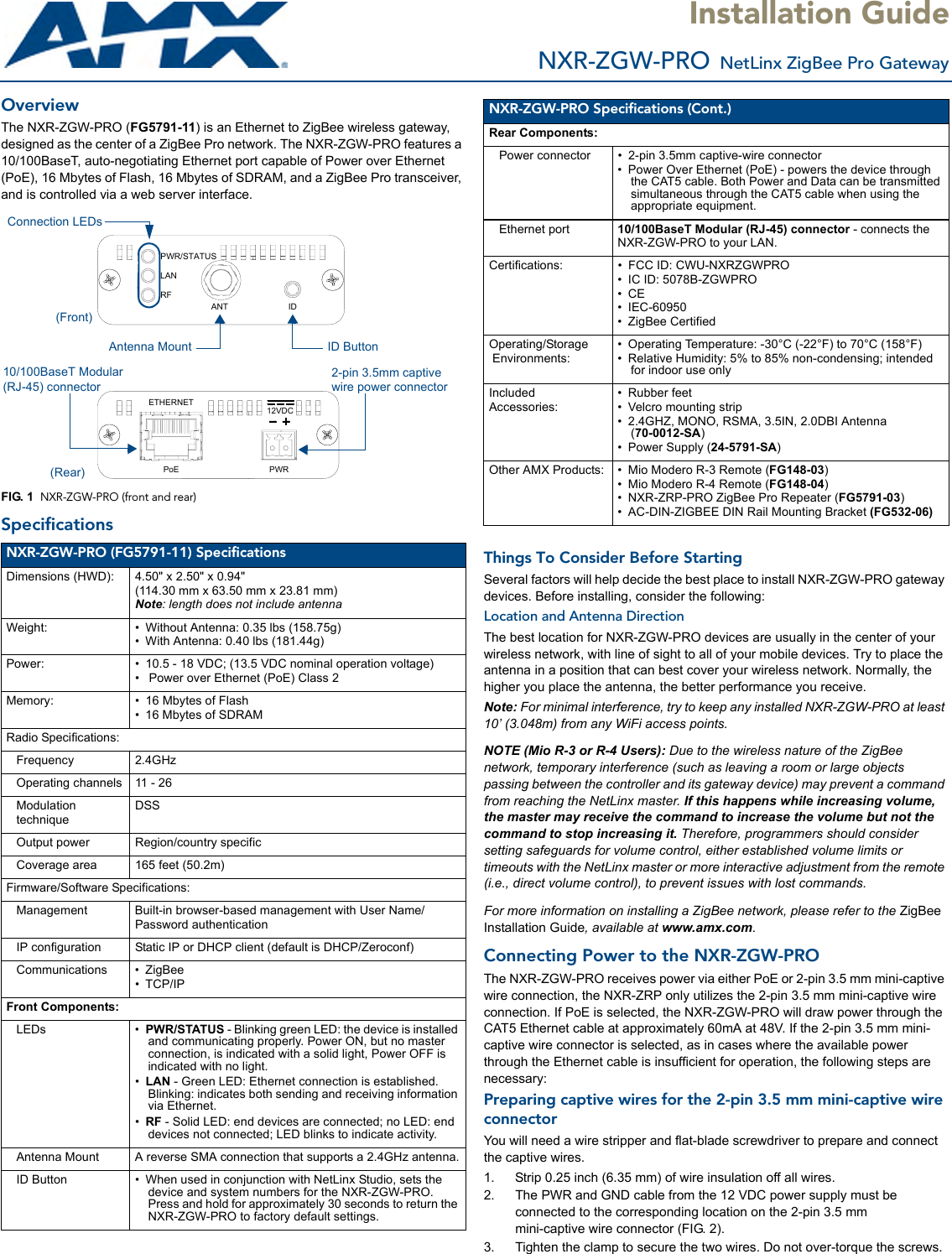
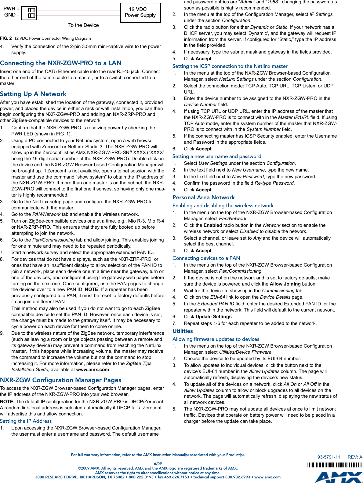
NXRZGWPRO User Manual
user manual
Navigation menu
Upload a User Manual
Namespaces
Wiki Guide
HTML
PDF
Info
Views
User Manual
Discussion / Help
Navigation