AMX RFIDBDG Anterus Badge Tag User Manual Anterus Installation Guide REV 0
AMX LLC Anterus Badge Tag Anterus Installation Guide REV 0
AMX >
user manual
Installation Guide
Anterus™ AMX RFID Solution
Overview
The Anterus™ RFID Solution provides a Radio Frequency IDentification (RFID)
solution from AMX that extends the capabilities of the integrated A/V or control system.
The Anterus solution uses RF technology to allow seamless identification of people,
assets, and objects.
Anterus components include:
•ANT-RDR Reader (FG5172): The ANT-RDR connects to the NetLinx controller
to initiate system events when an Anterus RF asset tag or ID badge passes into
its zone.
•ANT-TAG Device/Asset Tag (FG5172-01): The ANT-TAG device/asset tag
attaches to devices to identify and track their location, keep assets secure, and
trigger system events.
•ANT-BDG Badge Tag (FG5172-03): The ANT-BDG badge tag is worn by
personnel to identify them, track their location within a facility, and trigger system
events while in proximity to an Anterus reader.
•Anterus Duet Module: The Anterus Duet Module interfaces ANT-RDR Readers
with NetLinx controllers.
ANT-RDR RFID Reader
The ANT-RDR (FG5172) connects to the NetLinx controller to initiate system events
whenever an ANT-TAG Device/Asset tag, or ANT-BDG ID badge passes into its zone
(FIG. 2).
The ANT-RDR communicates with the NetLinx Master via AXLink, which supports up
to 255 devices on a single AXLink bus spanning for a total distance of 3000’ (915 m).
The ANT-RDR uses a 4-pin 3.5 mm mini-Phoenix (male) connector to provide data
and power to the ANT-RDR via the AXLink bus.
ANT-RDR Product Specifications
Anterus RFID Tags
The two types of RFID Tags (ANT-TAG, and ANT-BDG) are described in the following
subsections:
ANT-TAG Device/Asset Tag
The ANT-TAG Device/Asset Tag (FG5172-01) attaches to devices to identify and track
location, keep assets secure and trigger system events (see FIG. 1).
Attach the ANT-TAG to a stationary or mobile asset to monitor the location of the
asset. A tagged asset may be a non-controllable object not traditionally connected to a
Master Control System, or a mobile device that is regularly moved throughout a facility.
ANT-BDG ID Badge Tag
The ANT-BDG Badge Tag (FG5172-03) is worn by personnel to identify them, track
their location within a facility and trigger system events while in proximity to an
ANT-RDR RFID Reader (see FIG. 1).
FIG. 1 Anterus RFID Solution
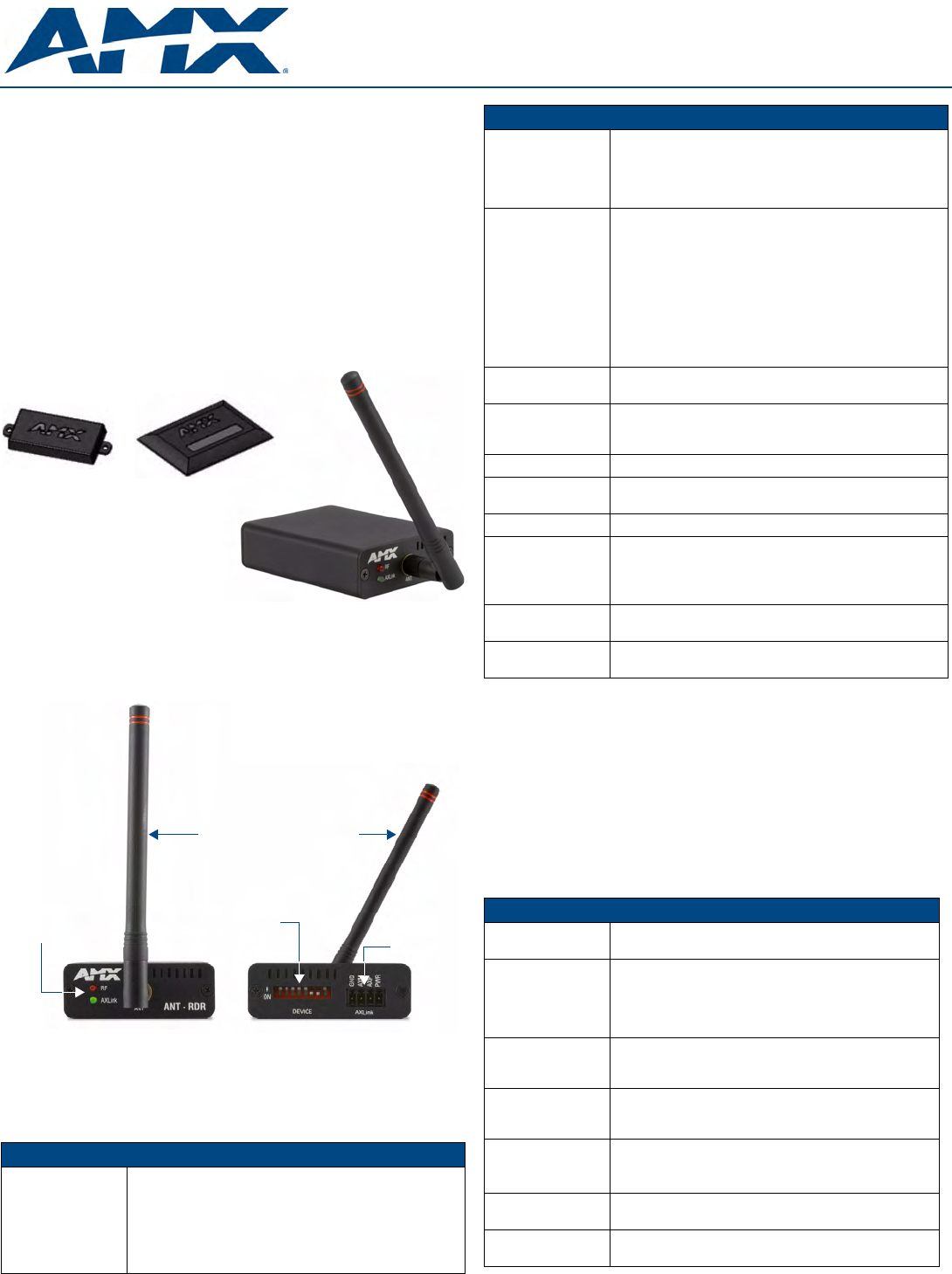
FIG. 2 ANT-RDR RFID Reader
ANT-RDR Specifications
Front Panel
Components:
• RF Status LED (amber): Indicates reception from RFID tag.
• AXLINK Status LED (green): Blinks to indicate the device
is installed and communicating properly.
Power ON, but no master connection, is indicated with a
solid light.
Power OFF is indicated with no light.
• RF Stub Antenna (433.92 MHz)
ANT-RDR
RFID Reader
ANT-TAG
Device/set Tag ANT-BDG
ID Badge Tag
Front Rear
8-position
DEVICE
DIP Switch
RF Antenna (433.92 MHz)
4-pin AxLink
Connector
AxLink/IR
Status LEDs
ANT-RDR Specifications (Cont.)
Rear Panel
Components:
• AxLink connector - 4-pin 3.5 mm mini-Phoenix (male)
connector provides data and power to the ANT-RDR.
• DEVICE ID 8-position DIP Switch - Used to set the unique
binary device number. The device number is set by the
total value of DIP switch positions that are ON (down).
RF Specifications: • Transmission Frequency: 433.92 MHz
Note: Anterus products are designed to not interfere with
WiFI and Zigbee frequency spectrum used by other AMX
products
• Transmission Range: Up to 100 feet/30 meters
(adjustable)
Note: Tag and Reader communication distances assume
optimal orientation between Tag and Reader. Read distances
may also vary as a result of the presence of metal and envi-
ronmental conditions.
Power
Requirements:
• 780 mW; ±12 VDC, 90 mA (max.)
• Power provided by 4-pin AxLink connector.
Environmental: • Operational temperature: 32º F to 140º F (0º C to 60º C)
• Storage temperature: -4º F to 158º F (-20º C to 70º C)
• Humidity: 5% to 90% (non condensing)
Enclosure: Black Metal Powder coat
Dimensions (HWD): • .906 x 2.500 x 3.424 (23.01 mm x 63.50 mm x 86.96 mm)
• Depth does not include antenna.
Weight: 1.59 oz. (45 grams)
Certification: The following standards applied in accordance with Article 5
of the directive, 1999/5/EC:
• EN 300 220-1 V1.2.1 (1997-11)
• ETS 300 683 (1997-03)
Included
Accessories:
•TBD
•TBD
Other AMX
Equipment:
• PoE Injector
•TBD
ANT-TAG / ANT-BDG Specifications
Models: • ANT-TAG Device/Asset Tag (FG5172-01)
• ANT-BDG ID Badge Tag (FG5172-03)
RF Specifications: • Tx Frequency: 433 Mhz
• Field strength: < 1600 µV/m
• Modulation: ASK
• Stability: Saw Stabilized
• External Antenna
Electrical
Specifications:
• Power: Internally powered Lithium Battery
(non-replaceable)
• Battery Life span: approximately 5 years.
Environmental: • Operational temperature: 32º F to 140º F (0º C to 60º C)
• Storage temperature: -4º F to 158º F (-20º C to 70º C)
• Humidity: 5% to 90% (non condensing)
Enclosure: ABS (ultrasonically sealed) IP 65
• ANT-TAG - Charcoal Grey
• ANT-BDG - Black
Dimensions (HWD): • ANT-TAG - 2.52" x 1.18" x .35" (64 mm x 30 mm x 9 mm)
• ANT-BDG - 3.38" x 2.12" x .19" (86 mm x 54 mm x 5mm)
Weight: • ANT-TAG - 0.53 oz. (15 grams) - excluding antenna
• ANT-BDG - 0.53 oz. (15 grams)
For full warranty information, refer to the AMX Instruction Manual(s) associated with your Product(s).
2/08
©2008 AMX. All rights reserved. AMX and the AMX logo are registered trademarks of AMX.
AMX reserves the right to alter specifications without notice at any time.
3000 RESEARCH DRIVE, RICHARDSON, TX 75082 • 800.222.0193 • fax 469.624.7153 • technical support 800.932.6993 • www.amx.com
93-5172-04 REV: A
Anterus Tags - Internal Battery
An internal lithium battery powers the Anterus RFID Tags. Each RFID Tag will, for the
duration of its life, transmit a Radio Frequency (RF) signal at a pre-set time interval.
The Tag life is estimated at 5 years at a transmission time interval of approximately
1.5 seconds. The life span of the Tag ends when the battery life is exhausted. Battery
status can be inferred by interrogating the internal Tag Age Counter Value.
Note: The internal lithium battery in the Anterus RFID Tags cannot be replaced.
Additional and replacement tags are available from AMX. Contact your customer
service representative for details.
Anterus Tags - Mounting/Installation
• ANT-TAG Tags can be mounted on a variety of non-metallic items. Where per-
manent fixing is required, VHB double-sided tape is used.
• ANT-BDG Tags can be mounted on a variety of items. Where permanent fixing
is required VHB double-sided tape is used; otherwise, the tags may be worn on
a necklace or clipped to clothing.
Anterus Tags - Antenna Orientation
For optimal RF reception, the tags should be mounted in the same orientation as the
antenna used on the reader (FIG. 3). The system will still function if the orientations
do no match: however, the range will be decreased. It is best to mount all tags in the
same orientation, no matter if it matches the orientation of the antenna.
Note: ANT-BDG ID Badge tags are typically worn on a necklace or clipped to
clothing, which typically results in a vertical antenna orientation. There is a horizontal
orientation for the ANT-BDG Tags, but it is typically reserved for installations that use
the ANT-BDG Tags as windshield-mounted vehicle tags.
Connecting the ANT-RDR To a NetLinx Master
The ANT-RDR uses a single 4-pin captive-wire AxLink port to connect the ANT-RDR
to a NetLinx Master, and (optionally) to other ANT-RDRs. To connect the ANT-RDR
to the NetLinx Master via AxLink, install the AXlink data/power bus wiring as shown
in FIG. 4.
Connecting Additional ANT-RDRs
To connect additional ANT-RDRs to create a RFID Reader Network Group, follow the
standard AxLink bus wiring (FIG. 5).
Preparing And Connecting Captive Wires
1. Strip 0.25 inch of wire insulation off all wires.
2. Insert each wire into the appropriate opening on the connector according to the
wiring diagrams and connector types described in this section.
3. Tighten the screws to secure the wires. Do not tighten the screws excessively;
doing so may strip the threads and damage the connector.
Assigning the ANT-RDR Device Address
The ANT-RDR sets its unique AXLink address via the 8-position DIP switch located
on the rear panel (see FIG. 2). AXLink addresses must be in the range of 1 to 255
(address 0 belongs to the Master).
The AXLink address distinguishes a device on the AXLink bus from other devices.
Care should be taken by the system integrator not to assign duplicate AXLink
addresses to multiple devices.
Note: The device number takes effect only upon power-up. If you later change the
device number, remove and reconnect the AXlink connector to enter the new device
number into memory.
Anterus Tag Addressing
Use the ANT-RDR’s built-in web console to add each Anterus Tag to the system,
assigning each one a unique Tag ID.
Accessing the Configuration Manager
The default IP Address for the ANT-RDR is 192.XXX.XXX.XXX.
From any PC that has access to the LAN that the ANT-RDR resides on:
1. Open a web browser and type the IP Address of the target ANT-RDR in the
browser’s Address Bar.
2. Press Enter to access the Configuration Manager for the specified device.
3. If prompted for a User Name and Password (FIG. 6), enter the defaults:
• Default User Name = Admin
• Default Password = 1988
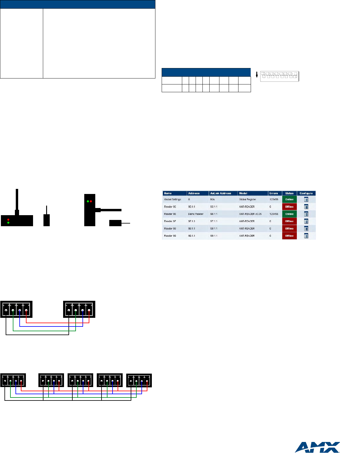
4. The initial view is the RFID Configuration Manager page (FIG. 6).
The options in this page allow you to view and configure the Anterus system
(Readers and tags) as a whole (Global Settings), as well as view and configure each
ANT-RDR Reader in the system individually. Configuration options include naming
each ANT-RDR, and managing each of the RFID Tags in the system.
Additional Documentation
Refer to the Anterus RFID Solution Operation/Reference Guide (available online at
www.amx.com) for additional information on installing and configuring the ANterus
RFID Solution.
ANT-TAG / ANT-BDG Specifications (Cont.)
Certifications: This device complies with Part 15 of the FCC Rules. Oper-
ation is subject to the following two conditions:
• This device may not cause harmful interference, and,
• This device must accept any interference received,
including interference that may cause undesired
operation.
The following standards applied in accordance with
Article 5 of the directive, 1999/5/EC:
• EN 300 220-1 V1.2.1 (1997-11)
• ETS 300 683 (1997-03)
Any modification of this device without the express consent
of the manufacturer could void the user authority to operate
the equipment.
FIG. 3 ANT-RDR / ANT-TAG Antenna Orientation
FIG. 4 AXlink data/power connections
FIG. 5 Connecting Additional ANT-RDRs
ANT-RDR ANT-TAG
Vertical Orientation Horizontal Orientation
ANT-RDR ANT-TAG
PWR
AXP
AXM
GND
ANT-RDRNetLinx Master
PWR
AXP
AXM
GND
PWR
AXP
AXM
GND
ANT-RDRNetLinx Master
PWR
AXP
AXM
GND
PWR
AXP
AXM
GND
PWR
AXP
AXM
GND
PWR
AXP
AXM
GND
ANT-RDRANT-RDR ANT-RDR
Device DIP Switch Settings
Position1234 5 6 7 8
Value 124816 3264 128
FIG. 6 RFID Configuration Manager - Main Page (initial view)
1 2 3 4 5678
ON
Example: Device #128