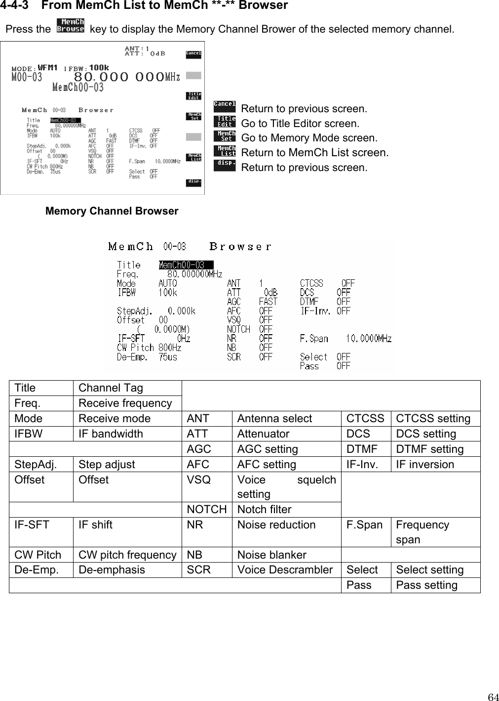
AOR USA AR-ALPHA Communications Receiver User Manual AOR AR ALPHA MANUAL
AOR USA Inc. Communications Receiver AOR AR ALPHA MANUAL
UserManual.wiki
>
AOR USA
>
AR ALPHA User Manual
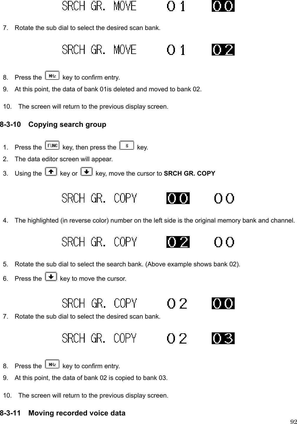
Users Manual
Navigation menu
Upload a User Manual
Namespaces
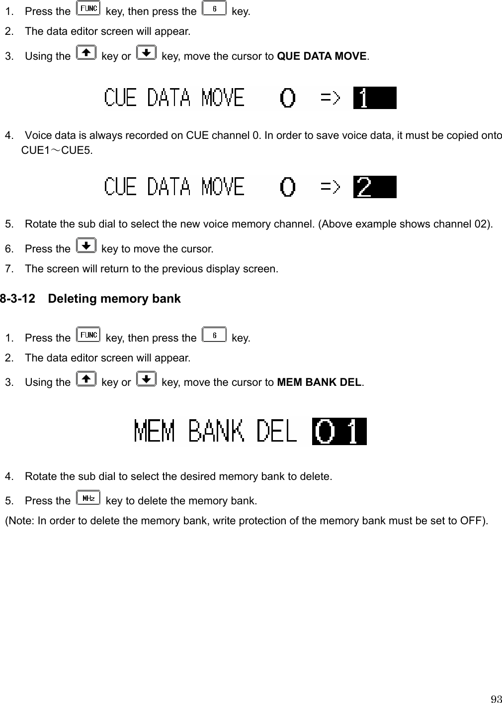
Wiki Guide
HTML
PDF
Info
Views
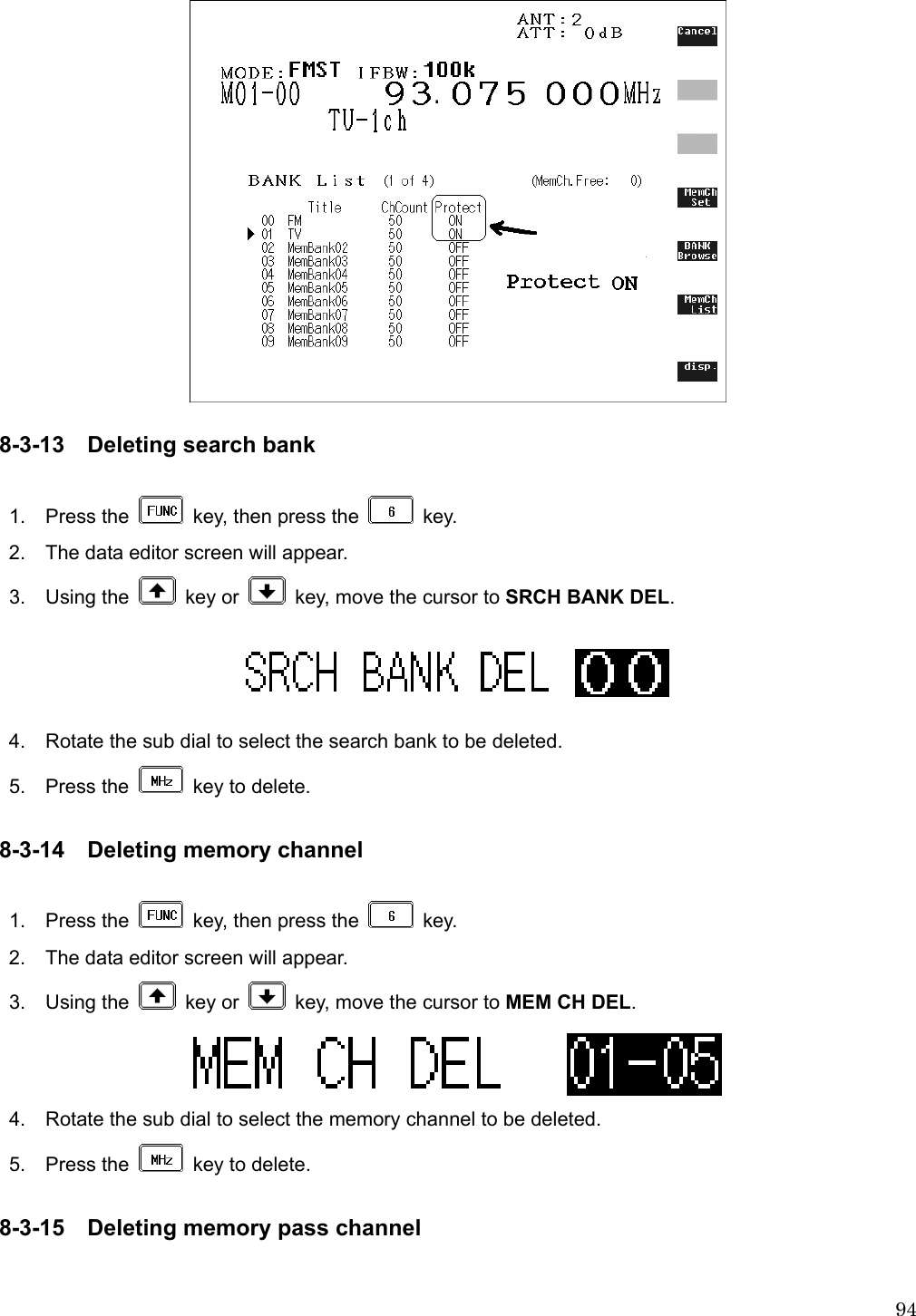
User Manual
Discussion / Help
Navigation
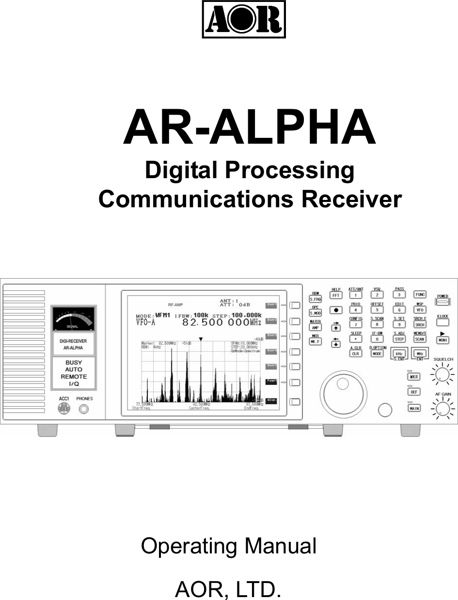
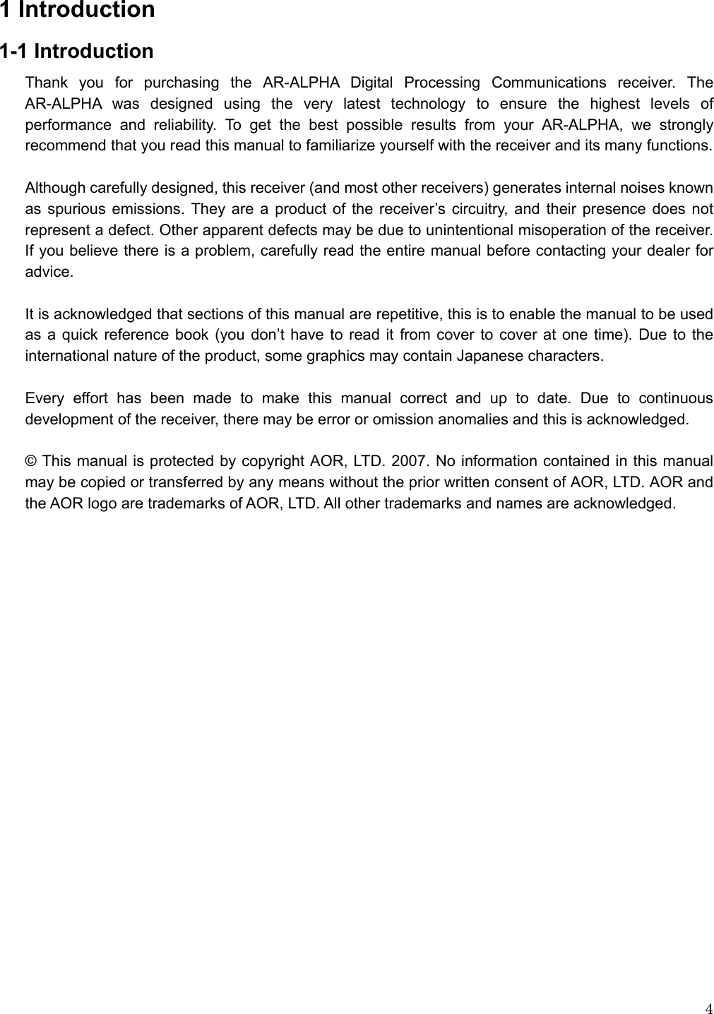

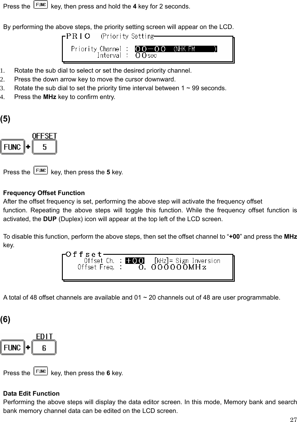
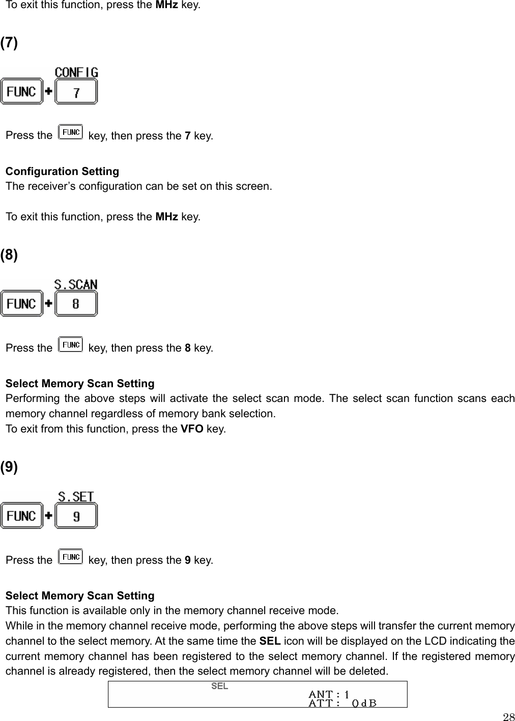
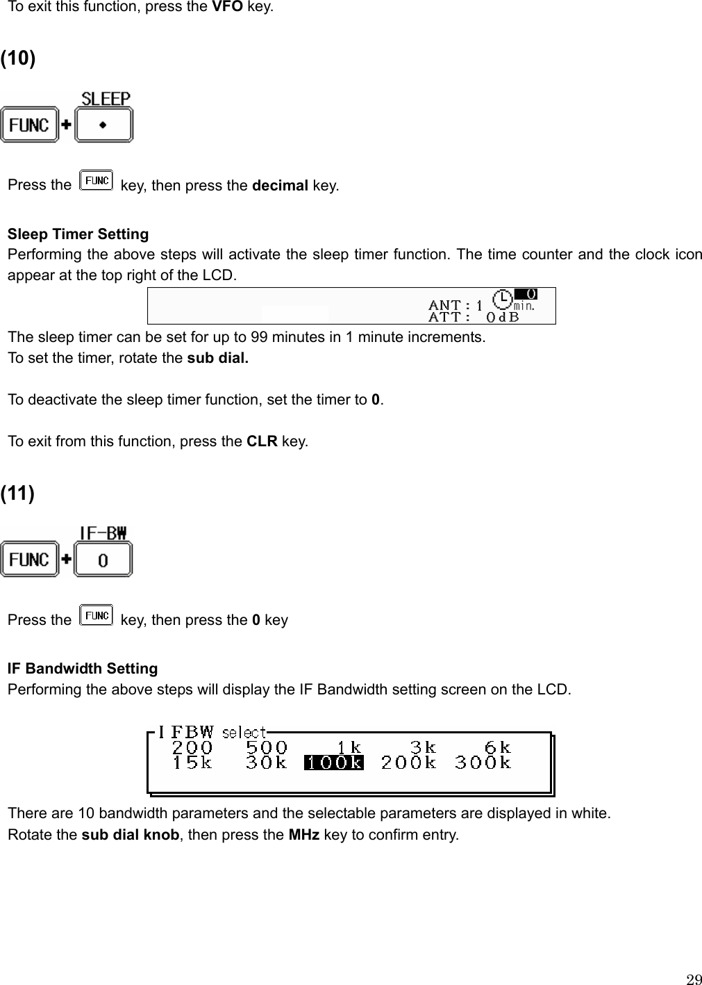
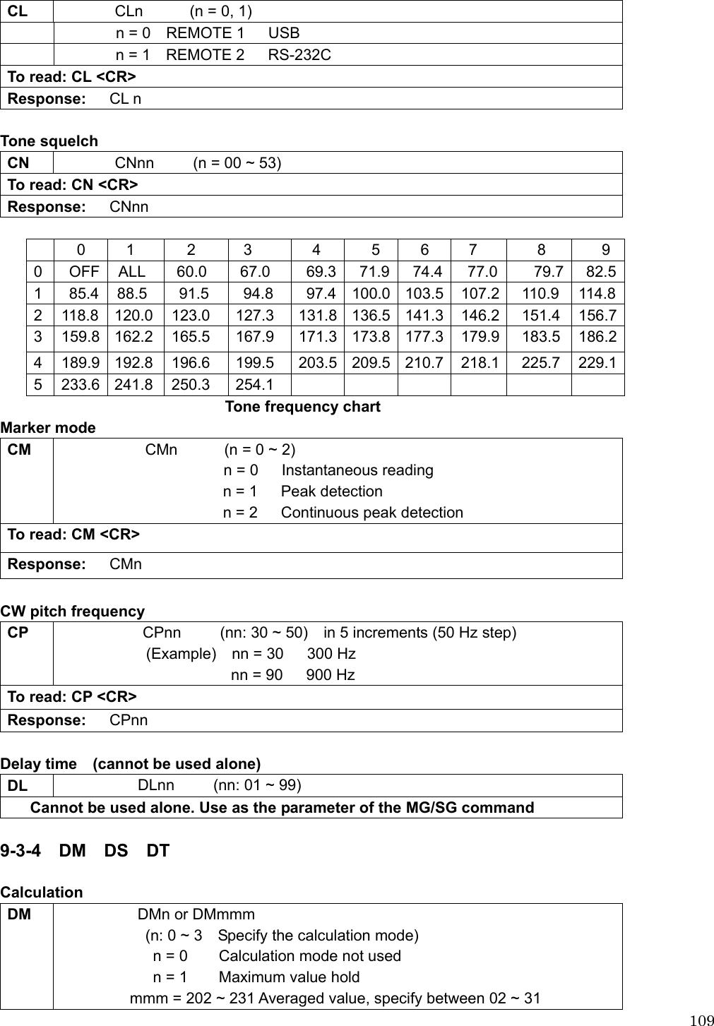
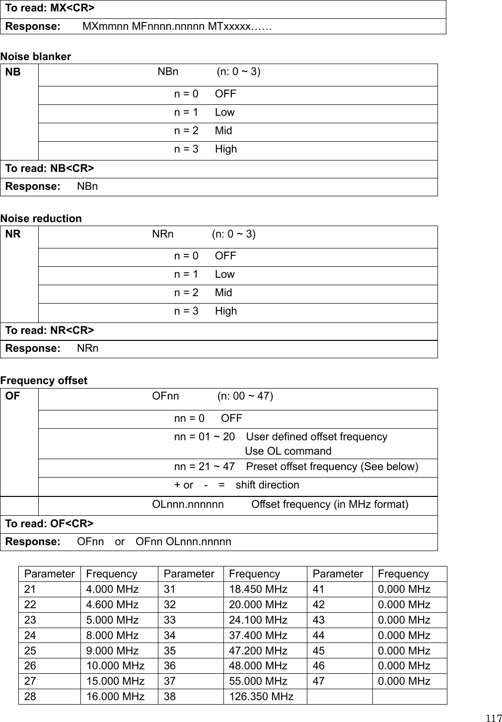
![37 Example of frequency entry for 162.55 MHz Press the [1] key, [6] key, [2] key, [.] key, [5] key, and [5] key. Press the [MHz] key. Example of frequency entry for 954 KHz (0.954 MHz) Press the [9] key, [5] key, and [4] key. Press the [KHz] key. Editing frequency input If there is an error during frequency input, press the CLR key. The frequency cursor will move backward and delete the last digit entry. Re-enter the correct number from the numeric keypad. Aborting frequency input If for some reason you do not wish to complete frequency input, press the key, then press the CLR key. 2-4-1-2 Changing frequency using the main tuning dial While in the VFO mode, a VFO frequency may be selected by using the main tuning dial, located at the right side of the front panel. You may rotate the dial ‘clockwise’ to increase frequency or turn ‘counterclockwise’ to decrease frequency.](https://usermanual.wiki/AOR-USA/AR-ALPHA/User-Guide-939520-Page-38.png)
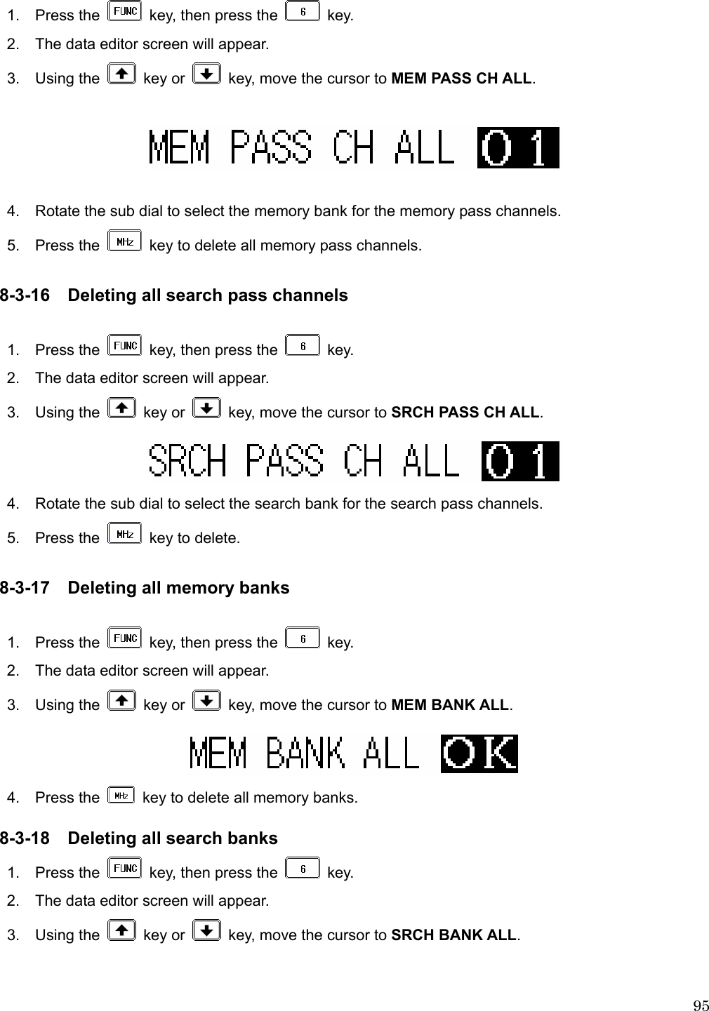
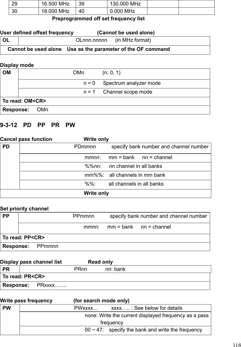
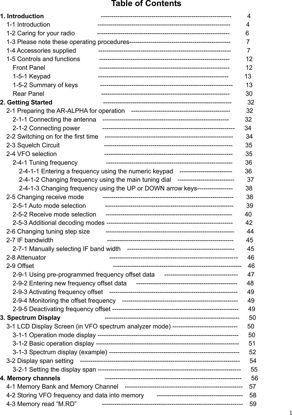
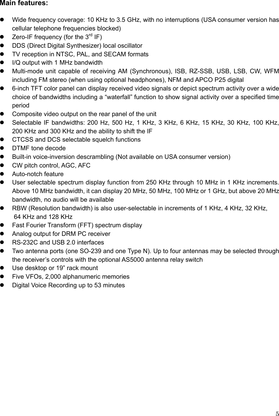
![106DATA BIT: 8 STOP BIT: 1 PARITY: NONE XFLOW: NONE A multiple command entry is only valid where specified. Where a multiple command entry is allowed, each command MUST be separated with a space “h20” (HEX DECIMAL). Each command is completed and a [CR] or [CR][LF]. Although there is no local echo, either [CR] or a specified response should come back from the receiver after confirming the correct command. If no response has been received after a short time, the receiver has failed to receive the command properly. Send a [CR] then re-send the command. Should a problem persist, check your connections or try reducing the baud rate. 9-2 Powering on the AR-ALPHA Connect a remote cable between the AR-ALPHA and a PC, type any key to power up the AR-ALPHA. 9-3 Detailed control command listings for the AR-ALPHA 9-3-1 ^A AC AF AG Remote power on ^Ann Remote ON Hex value 0x01 Accept a value nn in the range of 00-99 for remote connection AGC AC ACn (n: 0 ~ 3) n = 0 (AGC Fast) n = 1 (AGC Middle) n = 2 (AGC Slow) n = 3 (Manual gain control) To read: AC <CR> Response: ACn](https://usermanual.wiki/AOR-USA/AR-ALPHA/User-Guide-939520-Page-107.png)