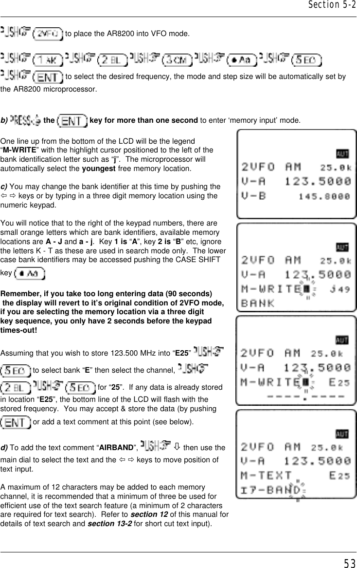
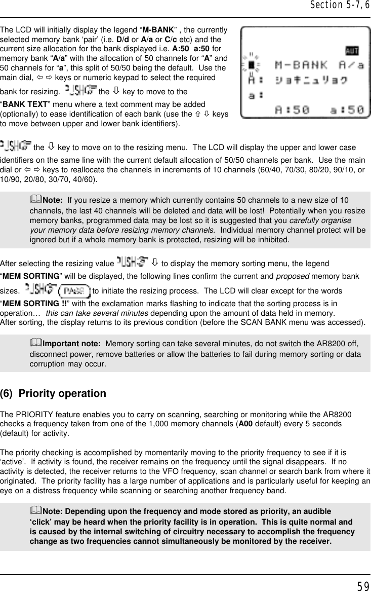
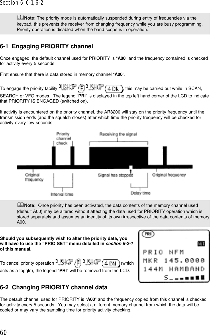
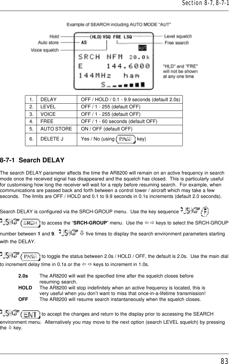
AOR USA AR8200MK3B Wide Band Scanning Receiver User Manual AR82002

AOR USA Inc. Wide Band Scanning Receiver AR82002

Contents

Part 2

51(5)  Memory channels & banksIt is convenient to store commonly used frequencies into a memory channel along with mode etc, thissaves having to key the data in over and over again.  Memory read is very straightforward and quickwhen compared to re-typing all data.5-1  Memory channel overviewThink of memory channels as pages in a notebook each of which is numbered to identify it.  Data may bewritten to each new page (memory channel) and each page may be overwritten with new data, they canbe used over and over again.  The AR8200 has 1,000 memory channels in addition to 10 ‘quickmemory’ channels and a priority channel.Each memory channel may hold:l  one frequencyl  receive model  tuning stepl  step-adjustl  frequency offsetl  attenuator settingl  noise limiter statusl  AFC statusl  pass statusl  write protectl  text comment of up to 12 charactersThe alphanumeric comment may be used to ease identification at a later date and to provide text searchfacilities.The 1,000 memory channels are divided into 20 banks, each initially having 50 channels.  The memorybanks are identified by letters A, B, C, D, E, F, G, H, I, J  (upper case letters) and a, b, c, d, e, f, g, h, i, j(lower case letters) and initially numbered from 00 to 49.Examples are “A00” for the first channel location in memory bank “A” and “A49” for the last memorychannel in memory bank “A”.  “e15” is the location of memory bank “e” (lower case) channel “15”.During the manufacture and testing of the receiver, various test frequencies may be entered into thereceiver’s memory banks so the memory locations may not be completely blank.&Note: Where memory channels and banks are empty the indication “- - -” is often displayed.The stored data may be quickly and easily recalled, changed or deleted using the memory recall, editand delete facilities.&Note:  It is suggested that one or two frequencies be held in each memory bankto make the recalling and scrolling of memory banks fluent, if no data is stored, theAR8200 may take up to 5 or 6 seconds to respond when attempting to change memorybank while the CPU checks for data.Section 5, 5-1
52Auto-storeWhen shipped from the factory, memory bank “J” is reserved for auto-store of memory channelsfrom search mode.  This is a useful facility to quickly build a list of active frequencies.  Please referto section 8-7-5 of this manual for further information regarding AUTO-STORE.Dynamic memory bank resizingThe lettered memory banks are regarded as a ‘pair’ making a total of 100 memory channels per bank,initially equally divided between the upper and lower case letters.  It is however possible to reallocate the100 channels in blocks of 10 channels between the same letters A/a, B/b, C,c etc  This means that theinitial 50/50 may be reallocated as 60/40, 70/30, 80/20, 90/10, or 10/90, 20/80, 30/70, 40/60.  This‘dynamic’ memory reallocation can be useful to optimise the memory layout where a large or smallcollection of frequencies need to be monitored without unnecessarily wasting memory banks with just afew channels occupied.Write protectIt is possible to write protect individual memory channels to prevent accidental deletion, whole memorybanks and a ‘global’ write protect facility are also available.Memory backupThe data contents of memory and search banks are held in an flash-ROM so that no backup battery orcapacitor is required for memory retention.&Note: When the AR8200 is switched OFF, all VFO data will be automatically stored.Should the NiCads (or dry batteries if in use) become completely exhausted, the last storedmemory channel or last VFO data ‘may’ be lost if the AR8200 is not powered-down using the key and insufficient power is available to save the data.5-2  Storing VFO frequencies & data into memoryIt is possible to save frequencies to the ten quick memories for simple recalling but for longer-termstorage, the 1,000 main memory channels offer a better and more flexible system.The process to save a displayed VFO frequency to memory is as follows:a) In VFO mode, select the required frequency, mode, attenuator etcb)     to initiate memory writec) Use the keypad, main dial or ïðñò keys to select the desired memory location   (BANK and CHANNEL)d) Add a text comment (optional) or delete an existing commente) Add memory channel write protect (optional)f) Exit the menu to save the data to the specified memory locationLets assume that you wish to store the frequency of 123.500 MHz(with the attenuator off, noise limiter off, AFC off) into memory bank“E” location “25” (E25) while in VFO mode with the text comment of“AIRBAND”.  If a mistake is made during programming,   the key to abort entry and return to 2VFO mode.a) Start by selecting VFO mode then key in the frequency of 123.500MHz, “mode and step size” are set to the default auto “AUT” (if notuse the key sequence        )Section 5-1, 5-2
53  to place the AR8200 into VFO mode.                   to select the desired frequency, the mode and step size will be automatically set bythe AR8200 microprocessor.b)  the   key for more than one second to enter ‘memory input’ mode.One line up from the bottom of the LCD will be the legend“M-WRITE” with the highlight cursor positioned to the left of thebank identification letter such as “j”.  The microprocessor willautomatically select the youngest free memory location.c) You may change the bank identifier at this time by pushing theï ð keys or by typing in a three digit memory location using thenumeric keypad.You will notice that to the right of the keypad numbers, there aresmall orange letters which are bank identifiers, available memorylocations are A - J and a - j.  Key 1 is “A”, key 2 is “B” etc, ignorethe letters K - T as these are used in search mode only.  The lowercase bank identifiers may be accessed pushing the CASE SHIFTkey Remember, if you take too long entering data (90 seconds) the display will revert to it’s original condition of 2VFO mode,if you are selecting the memory location via a three digitkey sequence, you only have 2 seconds before the keypadtimes-out!Assuming that you wish to store 123.500 MHz into “E25”  to select bank “E” then select the channel,    for “25”.  If any data is already storedin location “E25”, the bottom line of the LCD will flash with thestored frequency.  You may accept & store the data (by pushing or add a text comment at this point (see below).d) To add the text comment “AIRBAND”,   ò then use themain dial to select the text and the ï ð keys to move position oftext input.A maximum of 12 characters may be added to each memorychannel, it is recommended that a minimum of three be used forefficient use of the text search feature (a minimum of 2 charactersare required for text search).  Refer to section 12 of this manual fordetails of text search and section 13-2 for short cut text input).Section 5-2
54If the memory location has been used previously and a text comment is displayed,    todelete the existing comment.&Note: It is possible to use keypad short cuts to select text characters, please refer tosection 13-2 of this manual for further details.You may accept the new frequency and text comment “AIRBAND” by pushing   or you may addmemory channel write protect (see below).e) To add the memory channel write protect,   ò to access the “PROTECT” menu, the default isoff.     to toggle the status to “ON”.To accept the input and store the data to the specified location,   .  The display willrevert to 2VFO mode.&Important note: It is suggested that you do not use the write protect facility until you arefamiliar with the operation of the AR8200 as it will prevent certain functions being carried outat a future time.5-2-1  Another example of memory writeLet’s assume that you wish to store the frequency of 433.000 MHz auto-mode into memory location“d10” with the text comment of “70cm”.a)     to place the AR8200 into VFO mode        to select the desiredfrequency.b)   to initiate ‘memory input’ mode.c) Select the bank by pushing the ï ð keys and using the main dial for channel number, or by typing ina three character memory address using the numeric keypad.Assuming that you wish to store 433.000 MHz into “d10”    which acts as the CASESHIFT key to select the lower case banks then    to select bank lower case “d”.  Nextselect the channel      for “10”.  If any data is already stored in location“d10”, the bottom line of the LCD will flash with the stored frequency.You need to carry out this key sequence fluently within 2 seconds or the bank location will time out.The 2 second time out does not apply when the bank and channel are selected using the main dialand ï ð keys.Section 5-2, 5-2-1
55To recap:             Once the three digit memory location has been selected, the 2 second keypad time-out does not apply tothe rest of the sequence.d) To add the text comment “70cm”,   ò then use the main dial to select the text and theï ð keys to move position of text input.  To accept the new frequency and text comment “70cm”, , if you wish to add write protect   ò to access the PROTECT menu.&Note: If the memory location has been previously used and a text comment is displayed,    to delete the existing comment.e) In the write protect menu,    to toggle the statusto “ON”, the default is off.To accept the input and store the data to the specified location, .  The display will revert to 2VFO mode.5-2-2  Automatic memory allocationWhen you    to start the memory write sequence, the AR8200 will initially offer the firstavailable empty memory location which has no data stored in it.     to accept thechannel offered or choose another location as described in the previous sections.  Alternatively you may the ò key to add a text comment then complete memory write by pushing  .  If theAR8200 has to look through many full memory channels before an empty channel is located, themessage “MEM WRITE SEARCH BLANK CH” may be briefly displayed.5-3  Memory write protectAs indicated in section 5-2, it is possible to write protect memory contents to ensure that importantmemory channels are not accidentally over-written.  It is important to remember that by write protecting amemory channel, it may prevent certain facilities from being used (such as over-writing the memorychannel or copying / swapping memory data to it).The memory protect status may be assigned as the last stage of memory write (as per section 5-2 of thismanual) or toggled on/off using the memory channel EDIT facility, refer to section 9-6 of this manualregarding memory channel EDIT facilities, in particular MEMORY PROTECT.It is also possible to write protect a whole memory bank, this prevents accidental deletion of data whenresizing memory banks.Section 5-2-1, 5-2-2, 5-3
56The memory bank write protect may be toggled on/off using the SCAN environment menu accessed bythe key sequence         followed by four pushes of the ò key.    the to toggle bank select on/off and    to accept the changes and exit the menu.Please refer to section 7-8-6 of this manual for details on MEMORY BANK write PROTECT.&Note: Memory channel write protect prevents accidental over-writing and deletion of specificmemory channels but does not prevent loss of data due to memory resizing or when using theoptional external memory slot card.5-4  Memory read “M.RD”Once frequency and mode data has been stored into a memory location, its retrieval is quick and simple.Let’s assume that you wish to retrieve the frequency of 123.500 MHz which has been programmed intoto memory “E25” during an earlier example in the preceding section 5-2 of this manual.  to place the receiver into memory read mode, the legend “M.RD” appears toward thetop left of the LCD to confirm operation. The AR8200 will monitor whatever memory channel first appearswhen you enter memory read.The AR8200 will display memory channel, mode, frequency, tuning step, text comment (if one was used),attenuator status, noise limiter status and  AFC status.  The memory channel last used (for memory writeor recall) will initially be displayed, If the desired memory channel is not immediately displayed it may berecalled by keying in the required three digit location.To recall memory channel “E25”          (there is no need to push enter).The “BANK/CH SEL” legend automatically appearswhen the first key is pushed to remind you that youare recalling memory channels in memory readmode.  Keypad memory recall requires a three digitlocation, one letter for the bank and two numbers forthe channel.  If you hesitate for more that 2 secondswhile recalling memory channels via the keypad thesequence will time out, for more leisurely memoryrecall use the ï ð ñ ò keys.To recall memory “b06” the CASE SHIFT key needs to be used to access the lower case bank,        (there is no need to pushenter).  If you attempt to recall a memory which has no valid data (because it is blank) the next validmemory channel will be displayed instead.  Blank memory channels are ignored.Section 5-3, 5-4
575-4-1  Memory channel review / huntFrom VFO mode    to enter memory read “M.RD” mode.The main dial may be rotated or the ñ ò keys pushed to review, hunt for and select memory channelsone by one, channels with no data stored will be skipped.    the ï ð keys to move betweenmemory banks one by one.&Important note: It is suggested that each memory bank be programmed with at least onememory channel otherwise the AR8200 may appear slow or sluggish when recalling banksas the CPU has to check all memory channels for valid data, this is particularly noticeable ifjumping between bank “A” and “j” (opposite ends of the AR8200 memory map).Memory read using the main dial and ï ð ñ ò keys is useful for reviewing memory contents andhunting for a specific channel if you forget where you stored it!  Should you know the number of therequired memory channel, the keypad method of memory recall will be much faster.  The AR8200 willmonitor whichever memory channel is displayed in memory read “M.RD” mode.It is also possible to hunt for memory channels using the TEXT SEARCH facility, please refer tosection 12-2 of this manual for further details.5-5  Deleting memory channelsIt is possible to over-write a memory channel with new data, edit the contents of a memory channel ordelete the channel entirely.  When in memory read mode, use the key sequence     to access the “MEM DELETE” menu.  The LCD menu invites you to “PUSH ENTER”to delete the current memory channel,    to delete it or    to abort.When deleted, the AR8200 increments to the next memory channel which contains data.  It is alsopossible to delete whole memory banks in one go using the DELETE menu.  Please refer to thesection 10-3 of this manual relating to memory bank DELETE options.Section 5-4-1, 5-5
585-5-1  Memory channel editingIt is possible to copy, move, swap and edit memory channels to assist the management of data.Please refer to section 9 of this manual regarding the EDIT menu.5-5-2  Adding text names to memory banksTo assist with memory management and identification, memory banks can be named.  The SCAN BANKmenu is used to add or edit memory bank names.To access the SCAN BANK menu        .  The LCD will initially display thelegend “M-BANK”, the currently selected memory bank ‘pair’ (i.e. D/d or A/a or C/c etc) and the currentsize allocation for the bank displayed i.e. B:50  b:50 for memory bank “B/b” with the allocation of 50channels for “B” and 50 channels for “b”, this split of 50/50 being the default.Use the main dial, ï ð keys or numeric keypad to select the required bank you wish to add a name to. the ò key to move to the “BANK TEXT” menu.Use the ñ ò keys to move between upper and lower bank identifiers, add text using the main dial andï ð keys or use the keypad.  To save the data and exit the menu    .5-6  Transfer of memory channel to VFOWhile in memory read, should you wish to tune away from the memory channel and benefit from nothaving to re-enter the frequency, mode etc, the data may be quickly transferred from memory to ‘VFO’mode.To transfer memory channel data to VFO simply   .  The LCD will display the legend“VFO” along with receive frequency, receive mode, tuning step size and other relevant information suchas attenuator, noise limiter and AFC status.  You may monitor the frequency or tune away from it usingthe main dial or ï ð ñ ò keys.5-7  Dynamic memory bank resizingThe lettered memory banks are regarded as a ‘pair’ making a total of 100 memory channels per bank,initially equally divided between the upper and lower case letters.  For example memory bank “A” willhave 50 channels numbered from 00 to 49 (A00 - A49) and memory bank “a” will also have 50 channelsnumbered from 00 to 49 (a00 - a49) making a total of 100 channels.It is possible to reallocate the 100 channels in blocks of 10 channels between the same letters A/a, B/b,C,c etc  This means that the initial 50/50 may be reallocated as 60/40, 70/30, 80/20, 90/10, or 10/90,20/80, 30/70, 40/60.  This ‘dynamic’ memory reallocation can be useful to optimise the memory layoutwhere a large or small collection of frequencies need to be monitored without unnecessarily wastingmemory banks with just a few channels occupied.The SCAN BANK menu is used to customise many features including memory bank resizing.To access the SCAN BANK menu        .Section 5-5-1, 5-5-2, 5-6, 5-7
59The LCD will initially display the legend “M-BANK” , the currentlyselected memory bank ‘pair’ (i.e. D/d or A/a or C/c etc) and thecurrent size allocation for the bank displayed i.e. A:50  a:50 formemory bank “A/a” with the allocation of 50 channels for “A” and50 channels for “a”, this split of 50/50 being the default.  Use themain dial, ï ð keys or numeric keypad to select the requiredbank for resizing.    the ò key to move to the“BANK TEXT” menu where a text comment may be added(optionally) to ease identification of each bank (use the ñ ò keysto move between upper and lower bank identifiers). the ò key to move on to the resizing menu.  The LCD will display the upper and lower caseidentifiers on the same line with the current default allocation of 50/50 channels per bank.  Use the maindial or ï ð keys to reallocate the channels in increments of 10 channels (60/40, 70/30, 80/20, 90/10, or10/90, 20/80, 30/70, 40/60).&Note:  If you resize a memory which currently contains 50 channels to a new size of 10channels, the last 40 channels will be deleted and data will be lost!  Potentially when you resizememory banks, programmed data may be lost so it is suggested that you carefully organiseyour memory data before resizing memory channels.  Individual memory channel protect will beignored but if a whole memory bank is protected, resizing will be inhibited.After selecting the resizing value   ò to display the memory sorting menu, the legend“MEM SORTING” will be displayed, the following lines confirm the current and proposed memory banksizes.     to initiate the resizing process.  The LCD will clear except for the words“MEM SORTING !!” with the exclamation marks flashing to indicate that the sorting process is inoperation…  this can take several minutes depending upon the amount of data held in memory.After sorting, the display returns to its previous condition (before the SCAN BANK menu was accessed).&Important note:  Memory sorting can take several minutes, do not switch the AR8200 off,disconnect power, remove batteries or allow the batteries to fail during memory sorting or datacorruption may occur.(6)  Priority operationThe PRIORITY feature enables you to carry on scanning, searching or monitoring while the AR8200checks a frequency taken from one of the 1,000 memory channels (A00 default) every 5 seconds(default) for activity.The priority checking is accomplished by momentarily moving to the priority frequency to see if it is‘active’.  If activity is found, the receiver remains on the frequency until the signal disappears.  If noactivity is detected, the receiver returns to the VFO frequency, scan channel or search bank from where itoriginated.  The priority facility has a large number of applications and is particularly useful for keeping aneye on a distress frequency while scanning or searching another frequency band.&Note: Depending upon the frequency and mode stored as priority, an audible‘click’ may be heard when the priority facility is in operation.  This is quite normal andis caused by the internal switching of circuitry necessary to accomplish the frequencychange as two frequencies cannot simultaneously be monitored by the receiver.Section 5-7, 6
60&Note: The priority mode is automatically suspended during entry of frequencies via thekeypad, this prevents the receiver from changing frequency while you are busy programming.Priority operation is disabled when the band scope is in operation.6-1  Engaging PRIORITY channelOnce engaged, the default channel used for PRIORITY is “A00” and the frequency contained is checkedfor activity every 5 seconds.First ensure that there is data stored in memory channel “A00”.To engage the priority facility        , this may be carried out while in SCAN,SEARCH or VFO modes.  The legend “PRI” is displayed in the top left hand corner of the LCD to indicatethat PRIORITY IS ENGAGED (switched on).If activity is encountered on the priority channel, the AR8200 will stay on the priority frequency until thetransmission ends (and the squelch closes) after which time the priority frequency will be checked foractivity every few seconds.&Note:  Once priority has been activated, the data contents of the memory channel used(default A00) may be altered without affecting the data used for PRIORITY operation which isstored separately and assumes an identity of its own irrespective of the data contents of memoryA00.Should you subsequently wish to alter the priority data, youwill have to use the “PRIO SET” menu detailed in section 6-2-1of this manual.To cancel priority operation         (whichacts as a toggle), the legend “PRI” will be removed from the LCD.6-2  Changing PRIORITY channel dataThe default channel used for PRIORITY is “A00” and the frequency copied from this channel is checkedfor activity every 5 seconds.  You may select a different memory channel from which the data will becopied or may vary the sampling time for priority activity checking.Section 6, 6-1, 6-2
61This is accomplished by using the “PRIO SET” menu accessed bythe key sequence        .The legend “PRIO SET” appears on the top line of the LCD toconfirm selection.6-2-1  Changing the priority channel data pickup channelShould you wish the priority channel to use data contained in another memory location, access the“PRIO SET” menu using the key sequence        , the legend “PRIO SET”appears on the top line of the LCD to confirm selection.Select the new location for data pickup by the priority channel, use the main dial to move through thememory locations one at a time or use the ï ð keys to move between banks, alternatively quickly key ina three digit memory location via the keypad.For example, select memory location “A23” using the key sequence       .The priority interval time menu may be accessed using the ò key or    to exit the menu.The newly nominated channel data will be used for priority monitoring.&Note: If you attempt to nominate a channel which contains no data, the input will beignored and the previously used data will continue to be employed.6-2-2  Changing priority interval timeShould you wish to check the priority frequency more or less often, the sampling time (interval) may beset using the “PRIO SET” menu.  Use the key sequence         to access the“PRIO SET” menu.    the ò key to move the cursor to the “INTERVAL” input line.Use the main dial to vary the interval time in increments of 1 second, the ï ð keys may be used to varythe interval time in increment of 10 seconds.  Priority time may be varied between the range of 1s to 99s. the   key to act as a short cut to 5 seconds (default).The more often you check the priority channel, the greater chance you have of ‘catching’ activity,however the greater the interruption to normal monitoring.  to accept the input and exit the menu.&Note:  Priority interval time is also used for VFO SCAN timings.Section   6-2, 6-2-1, 6-2-2
62(7)  SCAN - scanning memory channels & banksThe AR8200 has a SCAN mode whereby the contents stored in the MEMORY CHANNELS AREAUTOMATICALLY RECALLED AND MONITORED very quickly for activity - scanned.* It is important that you do not confuse SCAN and SEARCH modes. *SEARCH mode (covered later in this manual) automatically TUNES THE RECEIVERTHROUGH ALL FREQUENCIES between two specified frequency limitslooking for active frequencies.7-1  SCAN - outline introductionDuring SCAN, the AR8200 automatically recalls each memory channel which contains data in numericorder and monitors it looking for activity.  When an ‘active’ memory channel is located (when a signal isfound and the squelch is open) the AR8200 will temporarily stop scanning.At default when shipped from the factory, the AR8200 will remain on the active memory channel untilthe received signal disappears and the squelch closes.  The CPU will then wait a further 2 seconds incase a reply is audible (such as aircraft and air traffic communications) and will then resume scanningthe memory channels again.If the ñ ò keys are pushed or the main dial rotated (while scanning or when stopped on an activechannel), the receiver resumes scanning in the direction of the arrow key or rotation.  This is particularlyuseful for taking a second look a channels which have just been scanned.Additional facilities available in SCANMemory banks may be “LINKED” and “UNLINKED” to effectively make larger or smaller groups ofmemories which may be scanned together.“PASS” may be used whereby memory channels can be skipped when not required (such as whenpermanently busy), they may be easily reinstated at a later time.“AUTO STORE” reserves memory bank “J” so that active frequencies found while conducting aSEARCH  may be automatically written to memory.  This is a useful tool for compiling an activity list ofrarely used frequencies especially when unattended.  Refer to section 8-7-5 of this manual for furtherinformation relating to auto store.It is possible to alter the sequence of scanning events using the SCAN ENVIRONMENT menu.  Thereare several scanning parameters which may be changed to suit your preferences and requirementsDELAY, LEVEL, VOICE, FREE & MODE, it is possible to mix combinations of all parameters.7-2  SCAN considerationsIt is presumed that you have already stored your favourite and commonly used frequencies into thememory banks (as per section 5-2 of this manual).A total of 1,000 memory channels are provided which are divided into 20 banks, each (at default) having50 channels.  The memory banks are identified by letters A, B, C, D, E, F, G, H, I, J  (upper case letters)and a, b, c, d, e, f, g, h, i, j (lower case letters) and numbered from 00 to 49.Section 7, 7-1, 7-2
63When in SCAN MODE, the memory banks are referred to as “SCAN BANK A”, “SCAN BANK B”,“SCAN BANK f” etc rather than using the full title “SCAN MEMORY BANK A”, “SCAN MEMORY BANK B”etc.  This terminology has been employed to make the explanation of and referral to SCAN MEMORYBANKS (SCAN BANKS) less long-winded.When shipped from the factory, memory bank “J” is reserved for auto-store of memory channels fromsearch mode so may already have frequencies stored.Keep your memory banks tidy - for best scan speedIn order to achieve the maximum scanning speed, it is advisable to keep all similar frequencies andmodes grouped together within the memory banks.  The greater the frequency change between memorychannels, then the further the receiver’s VCO (Voltage Controlled Oscillator) has to travel and theslower the scan rates.  Similarly, when many changes of mode are called, more switching has to beaccomplished and the scan speed may be reduced.Memory channel data may be entered in duplicate into several channels.  This will ensure thechannel data is scanned more frequently to increase the chances of activity being detected.Limitations of SCAN modeShould a number of different modes and wide range of frequencies be used, then the SCAN processmay be affected by noise or differences in squelch characteristic on some frequencies and modes.To help provide the best operation of SCAN, additional facilities have been provided (configurable via theSCAN ENVIRONMENT menu).  Should you listen to noisy frequencies or bands containing carriers,make liberal use of the AUDIO, LEVEL and FREE scan facilities.7-3  Starting to SCANPresuming that some memory channels are programmed with data, to start the scan process will takeone or two pushes of the   key depending upon which operating mode is currently employed(in VFO and search mode the first press accessed memory read):-Memory read mode “M.RD”  VFO mode “VFO” or “2VFO”      Search mode “SRCH”      The legend “SCAN” is displayed toward the top left of the LCD to indicate that the SCAN process hasbeen started, a bank letter will also be displayed representing the current bank.  Ensure that thesquelch control is advanced clockwise to threshold point so that background noise is cancelledand the squelch closes (otherwise scan will not operate).Section  7-2, 7-3
64When SCAN has been selected, only the currently displayed memory bank WHICH CONTAINS DATAwill be SCANNED (as bank link is default off), receive mode and frequency are unimportant.  Anymemory channels which contain no data (empty) will be ignored (skipped).7-3-1  Transfer of active memory to VFOWhen the scan process is paused on a busy channel,    to transfer the current memoryfrequency to VFO where it may be monitored.7-4  Selecting a scan bankThe memory bank identifier (such as “A”) will bedisplayed on the left of the LCD under the legend“SCAN”.  If more than one memory channel isprogrammed into the current memory bank thechannel numbers will be changing.When an ‘active’ channel has been located (busy, so thesquelch opens) the scan process willtemporarily pause on the active channel, the memorylocation (such as “A03”) will be displayed along withany accompanying text (displayed underneaththe memory location).To select another memory bank forscanning, use the ï ð keys or the corresponding letter on thekeypad from A to J, for lower case banks the   CASE SHIFTkey first.If no data is available,the next bank withvalid data will berecalled (emptymemory banks areskipped).To scan more that onememory bank at atime, please refer tothe scan bank linkingsection 7-7 of thismanual.7-5  Channel PASSWhen scanning, you may encounter active memory channels which you do not wish to currently monitor.It is possible to manually force the scan process to continue by pressing the   key or ñ ò keysbut this manual intervention can be an annoyance.  For this reason it is possible to temporarily PASSSection 7-3, 7-3-1, 7-4, 7-5
65unwanted channels so that they are skipped when scanning.  PASSdoes not delete the memory contents but simply ‘tags’ the channelto be skipped.  In memory read, the PASS tag may toggled on/offand the tags removed in one operation using the delete passchannel facility of the DELETE menu.While paused (during scan) on a busy channel which you do notcurrently wish to monitor,    to skip it.  The scanprocess will immediately move on to the next memory channel ofthe current bank in the direction (up or down) which has beenpreviously used for tuning or memory read.  This tagged memory channel will be skipped duringsubsequent scans until the tag is removed.  The legend “PAS” will have been assigned to the skippedmemory channel which may be reviewed in memory read mode.7-5-1  Toggling memory channel PASSThe   key may also be used to tag (skip) unwanted channels when in memoryread.  To cancel channel pass tag on a particular memory channel, recall it in memoryread mode then   .  The LCD legend “PAS” indicates when the channelis locked out, the   key toggles “PAS” on/off.7-5-2  Removing ALL memory PASS tags in one goIt is possible to remove the memory PASS tags of ALL memory channels in all banks in one operationusing the DELET menu.       to access the DELETE menu.    the ò key six times to displaythe menu option “DEL MEM PASS”.&Note: It will take a little while for the AR8200 to look for PROTECT channels and PASSchannels as you work through the menus.If at least one memory channel has been tagged PASS, the third line from the bottom of the LCD willdisplay a memory location such as “PASS-CH A17” with the “A17” simply confirming that at least onememory channel is tagged PASS.  If no memory channels have been tagged PASS, the LCD will display“PASS-CH ---”.To remove all memory PASS tags in one go   , the legend “MEM PASS CH ALL OFF!!” willbe displayed to show that removal of pass tags is in process followed by “MEM PASS CH SEARCH !!” asthe AR8200 checks that all tags have been removed.  The LCD will then display “PASS-CH ---” toconfirm that no channels are now tagged as PASS.  To exit the menu and return to the standard display  .Section  7-5, 7-5-1, 7-5-2
667-6  Deleting memory channelsAlthough it is possible to over-write memory channels with new data, edit memory channels, swap, copy,move and to PASS (skip) them, there will be occasions when you want to delete memory channelscompletely.7-6-1  Deleting single memory channelsWhile in memory read mode,         to delete the currently displayed memorychannel.  As a safe guard against accidental deletion you will be instructed to    toexecute the deletion, alternatively    to abort delete.Once memory channels have been deleted, the data is destroyed and cannot be recalled again.7-6-2  Deleting whole memory banks in one goShould you wish to delete the entire contents of a memory bank, the DELETE menu may be used, this isquicker than recalling each memory in memory read mode and deleting them individually, especially ifthere are more than about five or six channels involved.       to access the DELETE menu.    the ò key three times todisplay the menu item “DELETE MEM-BANK B00”.  The LCD will display a memory bank location suchas “MEM-BANK B00” with the “B00” being the last memory bank used.  Use the ï ð ñ ò keys to selectthe desired memory bank for deletion, alternatively type in the required bank letter via the keypad (theCASE SHIFT key   will be required to access the lower case memory banks).  If there are nochannels which contain data in the selected memory bank, the LCD legend “B --“ will be displayed with“B” being the current bank and “--“ indicating that no channels are available for recall or scan (as they areempty).To delete all memory channels from the displayed bank   .  After a few seconds the LCDwill display “DELETE MEM-BANK B--“ indicating that the selected bank no longer contains memory data.To exit the menu and return to the standard display    .7-7  Scan bank link (scan group)It is possible to custom define scan parameters for a single bankor group of memory banks.Use the key sequence         to accessthe “SCAN GROUP” menu.  Bank “SCAN GROUP 0” contains adefault listing and cannot be overwritten (so displays “LINK OFF”on the bottom line of the LCD), banks 1 to 9 are available forcustom programming.Use the main dial or ï ð keys to select the SCAN GROUPnumber, for SCAN-GROUP numbers 1 to 9 the legendSection 7-6, 7-6-1, 7-6-2, 7-7
67“BANK LINK” will be displayed on the bottom line ofthe LCD indicating that programming is possible. ò to move to the memory bank letters, thenreverse highlight the letters you wish to link togetheras a group of memory channels to scan using theï ð ñ ò keys,    to mark desiredmemory banks, both upper and lower case letters maybe highlighted in the same group.  The selected banks(which will form a large scan group) will be displayedin REVERSE contrast on the LCD.It is also possible to use the keypad to quickly select the required banks for inclusion as a group, thissaves having to use   to toggle selection, The CASE SHIFT key    is used to togglebetween the upper and lower case memory bank listings.  to accept the data input.     (one or twice) to start scanning if theAR8200 is not already in scan mode.  The memory banks grouped together in the SCAN GROUP willform a large group during scan.  The SCAN GROUP number (and associated data) will be used to definecurrent scan parameters.For example:  If you group banks “B, E, F, a, h” as SCAN GROUP number “1”, then when any one ofthese banks is scanned, all other banks in the group will be scanned in sequence over and over…B > E > F > a > h > B > E > F > a > h etc (providing each of the banks contains stored memorychannels).It is possible to scan ANY memory bank, even if it is not contained in the current SCAN GROUP list bymanually selecting the bank using the ï ð keys or keypad while in scan mode.You can individually configure each of the nine SCAN GROUPS1 to 9 with a different collection of banks.  SCAN GROUP 0cannot be changed as it contains the default of LINK OFF sothat you can quickly disable bank link when individual memoryscan is required.  SCAN GROUP 0 also contains defaultsettings for DELAY, LEVEL, VOICE, FREE and MODEparameters.To change the active SCAN GROUP, access the SCAN GROUPmenu using the key sequence        ,select the desired SCAN GROUP (0 to 9) using the main dial or ï ð keys then    toaccept the change and exit the menu.7-8  Additional scan facilities(Scan group environment - DELAY, LEVEL, VOICE, FREE, MODE)It is possible to further customise the scan parameters foreach of the nine SCAN GROUPS (group 0 cannot be alteredas it contains the default information).Section  7-7, 7-8
68Use the key sequence      to access the “SCAN-GROUP” menu.  Use theï ð keys to select the SCAN-GROUP number between 1 and 9.    ò three times to move downbeyond the bank link facility and onto the additional scan environment facilities: delay, level, voice, free,mode scan.1. DELAY OFF / 0.1 - 9.9 seconds (default 2.0s)2. LEVEL OFF / 1 - 255 (default OFF)3. VOICE OFF / 1 - 255 (default OFF)4. FREE OFF / 1 - 60 seconds (default OFF)5. MODE ALL, WFM, NFM, SFM, WAM, AM, NAM, USB, LSB, CW7-8-1  Scan DELAYThe scan DELAY parameter affects the time the AR8200 will remain on an active frequency in scanmode once the received signal has disappeared and the squelch has closed.  This is particularly usefulfor customising how long the receiver will wait for a reply before resuming scan.  For example, whencommunications are passed back and forth between a control tower / aircraft which may take a fewseconds.  The limits are OFF and 0.1 to 9.9 seconds in 0.1s increments (default 2.0 seconds).Scan DELAY is configured via the SCAN-GROUP menu.  Use the key sequence     to access the “SCAN-GROUP” menu.  Use the ï ð keys to select the SCAN-GROUPnumber between 1 and 9.    ò three times to display the scan environment parameters startingwith the DELAY.  to toggle the status between 2.0s  and OFF,the default is 2.0s.  Use the main dial to increment delay time in0.1s or the ï ð keys to increment in 1.0s.2.0s The AR8200 will wait the specified time after thesquelch closes before scan.OFF The AR8200 will resume scan instantaneouslywhen the squelch closes.  to accept the changes and return to the display prior to accessing the SCANenvironment menu.  Alternatively you may move to the next option (scan LEVEL squelch) by pressingthe ò key.7-8-2  Scan LEVELThe scan LEVEL squelch parameter causes the AR8200 to check the signal strength and to only openthe squelch when the signal strength is above the stated level (which is programmable in 256 steps).The limits are OFF and 1 to 255 (default off).Scan LEVEL is configured via the SCAN-GROUP menu.  Use the key sequence     to access the “SCAN-GROUP” menu.Section 7-8, 7-8-1, 7-8-2
69Use the ï ð keys to select the SCAN-GROUP number between 1 and 9.    ò four times todisplay the scan environment parameter of LEVEL.  as a short cut to off (which is the default).  Use the main dial to increment value by1 or use the ï ð keys to increment by 10.While adjusting level squelch, the “¬” legend will be displayed to the left of the value “LEVEL  ¬  3”indicating that the current value will not cause the squelch to close.  Increase the value until the “¬”legend is just extinguished (this may typically be around a value of 120 - 230), the current transmissionand signals below this level will be skipped.  There will be no audio produced when a transmission isencountered below the level configured even though the “S” squelch legend is displayed.   This is auseful alternative to regular squelch on noisy bands such as short wave.The approximate relationship between signal meter segments and level value is as follows:              1        2         3        4        5         6        7        8         9        10      11       12       13      14            124    141     154    168    178     185    193     200     203    206     208     210    212    214&Note:  When level squelch is in operation, the rotary squelch control is usually bestrotated to the fully anti-clockwise position.  to accept the changes and return to the display prior to accessing the scanenvironment menu.  Alternatively you may move to the next option (scan VOICE squelch) by pressing theò key.While scanning, the LCD legend “LSQ” is displayed to indicate that scan LEVEL squelch is in operation.7-8-3  Scan VOICEThe scan VOICE squelch parameter causes the AR8200 to check the current frequency for valid audioand to only open the squelch when audio above a specified level (which is programmable in 256 steps) isdetected.  The limits are OFF and 1 to 255 (default off).Scan VOICE is configured via the SCAN-GROUP menu.  Use the key sequence     to access the “SCAN-GROUP” menu.  Use the ï ð keys to select the SCAN-GROUPnumber between 1 and 9.    ò five times to display the scan environment parameter of VOICE.  as a short cut to off (which is the default).  Use the main dial to increment value by1 or use the ï ð keys to increment by 10.While adjusting voice squelch, the “¬” legend will be displayed to the left of the value “VOICE   ¬  12”indicating that the current value will not cause the squelch to close.  Increase the value until the “¬”legend is just extinguished (this may typically be around a value of 1 to 100), the current transmissionand signals with audio below this level will be skipped.  There will be no audio produced when atransmission is encountered with audio below the level configured even though the “S” squelch legend isdisplayed.Section  7-8-2, 7-8-3
70&Note:  When voice squelch is in operation, the rotary squelch control is usually best rotatedto the fully anti-clockwise position.  to accept the changes and return to the display prior to accessing the scanenvironment menu.  Alternatively you may move to the next option (scan FREE time) by pressingthe ò key.While scanning, the LCD legend “VSQ” is displayed to indicate that scan VOICE squelch is in operation.7-8-4  Scan FREEThe scan FREE time parameter determines how long the AR8200 will remain on an active frequencybefore resuming scan even though the frequency is still active.  This is useful if you wish to gain a snapshot of activity without the AR8200 being tied to a busy frequency for long periods of time (such as whenmonitoring active amateur band repeaters etc).  Scan FREE time saves you having to manually interveneto force the scan process to resume and saves the need to lockout memory channels using the channelPASS facility.  The limits are OFF and 01 to 60 seconds (default OFF).Scan FREE time is configured via the SCAN-GROUP menu.  Use the key sequence     to access the “SCAN-GROUP” menu.  Use the ï ð keys to select theSCAN-GROUP number between 1 and 9.    ò six times to display the scan environmentparameter of FREE.  to toggle between OFF and 5 seconds (the default is off).  Use the main dial toincrement value by 1s or use the ï ð keys to increment by 5s.  to accept the changes and return to the display prior to accessing the scanenvironment menu.  Alternatively you may move to the next option (scan receive MODE) by pressingthe ò key.While scanning, the LCD legend “FRE” is displayed to indicate that scan FREE time is in operation andthe scan process will only pause on active frequencies for the specified time.7-8-5  Scan (receive) MODEThe scan receive MODE parameter enables selected receive modes to be scanned in isolation eventhough memory banks may contain many different receive modes.  This saves the need to lockoutmemory channels using the channel PASS facility when only a certain receive mode is desired (such asAM for airband monitoring etc).Scan receive MODE is configured via the SCAN-GROUP menu.  Use the key sequence     to access the “SCAN-GROUP” menu.  Use the ï ð keys to select theSCAN-GROUP number between 1 and 9.    ò seven times to display the scan environmentparameter of MODE.Section 7-8-3, 7-8-4, 7-8-5
71  as a short cut to ALL (which is the default) which will cause all receive modes to bescanned in the specified scan group.  Use the main dial or ï ð keys to select the receive mode:ALL, WFM, NFM, SFM, WAM, AM, NAM, USB, LSB, CW.  to accept the changes and return to the displayprior to accessing the scan environment menu.  The ò key loopsback to the top of the SCAN-GROUP menu.While scanning, only memory channels with the correspondingreceive mode will be scanned.  The legend “SCAN NFM” or“SCAN AM” etc will be displayed indicating that only specificmodes will be scanned, the modes are displayed in REVERSECONTRAST highlighting.  If no channel contained within the bankgroup matches the specified receive mode, the scan will beaborted and the display will return to 2VFO mode with an errorbeep sounding (if the beep is enabled).7-8-6  Write protect of memory channels & banksIt is possible to write protect memory channels, whole memory banks, search banks and ‘globally protect’memory to prevent data being accidentally over-written.  Refer to section 11 of this manual regarding thewrite protect options.7-9  Select scanSelect scan enables you to ‘tag’ memory channels to make a temporary list of up to 100 channels forscanning in a separate list called the SELECT SCAN LIST.  Memory channels from any of the 20memory banks may be mixed together in any order and added to the select scan list.7-9-1  Adding select scan channels in memory readIn memory read mode or when paused on an active channel in scan mode use the key sequence       to toggle the select scan tag on/off, the legend “SEL” confirms selection.Even memories marked as channel pass may be added to the select scan list, the pass status will beignored by select scan.7-9-2  Starting  / stopping select scanTo start select scan you must first have at least two memorychannels tagged for select scan.        to start select scan.  The legend “SEL” will be displayed on the lefthand side of the LCD to indicate that select scan is in progress.The memory channels will be displayed as select scan progressesand each memory channel will display the legend “SEL”.  Thedirection of scan can be reversed using the main dial or ñ ò keys.To stop select scan,    or   or Section  7-8-5, 7-8-6, 7-9, 7-9-1, 7-9-2
727-9-3  Select scan environmentThe select scan environment may be customised in respect of DELAY, LEVEL, VOICE, FREE andMODE.  The current SCAN-GROUP selection is used by select scan.  To access the scan groupenvironment menu        .  For further information regarding the scan groupenvironment please refer to section 7-8 of this manual.7-9-4  Editing the contents of the select scan listAlthough it is possible to review all 1,000 memory channels using memory read to assess which memorychannels are tagged for select scan, a quicker method is available via the select scan menu.       to access the “SEL-SCAN” menu.One hundred select scan channels are available and numberedfrom 00 to 99.  Use the main dial or ï ð keys to scroll through theselect scan list contents.  The select scan numbers are allocated inthe order in which they were tagged in memory read mode, thememory bank/channel number, frequency and any text comment isdisplayed.Deleting singe select scan channelsTo remove the displayed channel from the select scan list   .  The frequency is removedfrom display (“SEL” tag is removed from the memory channel) and the position in the select scan list willbe filled with the next highest select scan channel number.  For example, if you have five select channelslisted and delete number “03”, channel number “04” will slide down to take its place(any gap is filled) so that “04” will be renumbered as “03”, “05” will become “04” and so on.Adding new select scan channelsIt is possible to tag select scan memories in memory read mode, it is also possible to add additionalselect scan channels using the select scan menu.       to access the select scan menu. the ï key to wrap around to the end of the select scanlist, the legend “SEL-SCAN xx --- ----.---- ------------“ will bedisplayed where “xx” is the next available select scan channel.The ‘dashes’ indicate that the channel is currently unused. ò to display the legend “BANK/CH SEL” inviting you toselect a memory channel to add to the select scan list.Select the desired memory channel by keying a three digit locationvia the keypad or scroll through the memory banks using the ï ðkeys and main dial to scroll through the memory channels.  to accept the displayed memory location to beadded to the select scan list.  The memory data will appear alongside the select scan number.Section 7-9-3, 7-9-4
73If you wish to add more select scan channels   ð once to move upward to the new end of thelist and repeat the process.     or   to exit the select scan menu.It is possible to delete the entire select scan list in one go using the DELETE menu, this is very useful toenable rapid changes to the select scan list content.7-9-5  Deleting all select scan channelsAlthough it is possible to review and delete select scan channels in memory read  and by using the selectscan menu, a quicker method is available should you wish to delete all select scan tags in one go.  Thisis particularly useful when you wish to start a new select scan list (making the select scan list almost likea note pad).The DELETE menu is used to delete all select scan channels in one go.  To access the delete menu      .    the ò key four times to display the “DELETE SEL-CH”menu.  If at least one select scan channel exists, a channel location will be displayed to the right of thelegend “SEL-CH Xxx” where “Xxx” represents the channel location, if no select scan channels exist thelegend “SEL-CH --” will be displayed.  to delete the select scan list, the “SEL-CH --“ legend confirms deletion.  or   or   or   or   to exit the delete menu.&Note: Only the select scan ‘tags’ are deleted using this procedure, the memory channelcontents are not erased or altered in any other way.Section  7-9-4, 7-9-5
74(8)  Search modeIn search mode, the AR8200 is programmed to automatically tune between two specified frequency limitslooking for activity.  Please refer to section 1-3 of this manual if you do not fully understand theterminology of SEARCH.8-1  Search typesThe AR8200 is equipped with two types of search:-VFO SEARCH = search from the current frequency in VFO mode.Please refer to section 4-3 of this manual for further information.PROGRAM SEARCH = search between user programmed limits.8-1-1  Program search overviewThere are 40 program search banks (referred to simply as search banks) which can be programmed withspecific parameters:l LO (lower) start frequencyl HI (upper) stop frequencyl Receive mode (or set to AUTO MODE)l Receive tuning step (or set to AUTO MODE)l Step adjustl Frequency offsetl Attenuator statusl Noise limiter statusl Text commentl Write protectl CTCSS tone (if the CT8200 SLOT CARD option is used)The program search banks are identified by upper case letters A - T and lower case letters a - t.  To helpwith identification, each bank may be labelled with an alpha-numeric text comment.Section 8, 8-1, 8-1-1
75To assist testing in the factory, several search banks may be programmed with data (which can be easydeleted or over-written).  This pre-programming is useful to ease familiarisation during the early days ofoperation… so that when you push a key there is something already programmed to work!8-2  Starting program searchPresuming that data is already stored into a search bank… the   key to start the program searchprocess.  The LCD legend “SRCH” will be displayed and aslong as the squelch is closed, the search process will startfrom the lower frequency limit and will progress toward theupper frequency limit.  When the program limit is reached,the search loops around and starts the process again.&Note: If no search banks have beenprogrammed, the search process will not operate.8-2-1  Reversing the          direction of searchTo reverse the direction ofsearch use the main dialor ñ ò keys, this is usefulto enable you to searchback over and over aninteresting point of thesearch process.8-2-2  Forcing the search to resumeIf the AR8200 stops on an unwanted busy frequency,   the   key or use the ñ ò keys ormain dial to force the search process to resume from the current frequency displayed.8-2-3  Stopping the searchWhile the search process is in progress (not stopped),    to stop searching and transferthe current frequency to the single VFO for monitoring or tuning from.  To exit the search process the   key for memory read mode or the   key for 2VFO mode (displaying thedata on-screen before search was started).Section 8-1-1, 8-2, 8-2-1, 8-2-2, 8-2-3
768-2-4  Copying an active frequency to the VFO or memory locationIt is convenient to transfer an active frequency from search to VFO or memory for periods of extendedlistening.Copy to VFOWhen the search process is stopped on an active frequency,   the   key to transfer thecurrent receive frequency to the single VFO where it may be monitored.Write to memoryWhen the search process is stopped on an active frequency,   the   key to write thecurrent receive frequency into the first available empty memory location (or you may select a specificlocation from the 1,000 memory channels available).8-3  Selection of search bankThere are 40 search banks, while searching use the ï ð keys to step through search banks whichcontain data, alternatively you may use the numeric keys (with assigned letters and shifts).  If no data isprogrammed in the nominated search bank, the next bank containing valid data will be used.Recalling search banks A - J is very simple involving only one key push, for this reason it is suggestedthat these banks are used for primary search tasks.While searching,   the numeric key corresponding to the required search bank:A *BCDEFGHIJ* When bank “A” is selected via the keypad, a delay of around two seconds will be encountered beforethe   key is acted upon, this is because the   key also has a special ‘SHIFT’ commandstatus when selecting banks K - T and k - t.Tip: to search “A” instantly,       Section 8-2-4, 8-3
77Recalling banks K - T requires use of the ‘SHIFT’command before the letter key, this ‘shift’command is the use of the   key before asecond numeric key is pushed.  You must keyquickly or bank “A” will be selected, the timeoutwhile using the ‘shift’ key is around two seconds:K  L  M  N  O  P  Q  R  S  T  Recalling banks a - j requires use of the ‘CASE’command before the letter key, this ‘case’command (selecting upper or lower case bankletters) is the use of the   key before asecond numeric key is pushed.a  b  c  d  e  f  g  h  I  j  Recalling banks k - t requires use of the ‘case’and ‘shift’ command before the letter key:k    l    m    n    o    p    q    r    s    t    Section 8-3
788-4  Programming a search bankEach of the 40 search banks may be programmed withdifferent frequency limits, receive modes, step size etc aslisted in section 8-1-1 of this manual.       to access the“SRCH-PROG” menu.Use the main dial or ï ð keys or keypad to select thebank you wish to program or over write.  (The ò key isused to move through the menu). òLO  Input the lower startfrequency in MHz format(don’t push enter) òHI  Input the higher end frequency in MHz format(don’t push enter) òMODE SET Use the ï ð keys or main dial to select receivemode, the   key is used as a short cut to “AUTO”.&Note: If the receive mode is set to “AUTO”, the receive mode,channel step, step-adjust, frequency offset will be taken from thepre-programmed auto band plan data, for this reason thedetailing will not be required while programming so is skipped…the next menu will be TEXT INPUT. òSTEP  Assuming that a receive mode other than “AUTO” was selected, you will be presentedwith the “SET STEP” menu.  Use the main dial or ï ð keys to select the required tuning stepfrom the following: 0.05 kHz (50 Hz), 0.1 kHz (100 Hz), 0.2 kHz (200 Hz), 0.5 kHz (500 Hz), 1.00kHz, 2.00 kHz, 5.00 kHz, 6.25 kHz, 8.33 kHz, 9.00 kHz, 10.00 kHz, 12.50 kHz, 20 kHz, 25.00kHz, 30 kHz, 50 kHz, 100.00 kHz.  Alternatively a step size may be entered in kHz format via thekeypad in multiples of 50 Hz in the range of 50 Hz to 999.95 kHz (do not push enter).Section 8-4
79&Note: If a step-adjust value is already programmed into the search bank, the step-adjustmenu will be automatically displayed when accessing the step input menu.STEP ADJ+  If you with to manually enter a step-adjust value for tracking unusual band plans , the “STEP ADJ+” legend will be displayed.    ò to move the cursorto the “ADJ+” line and enter a step-adjust value using kHz format (do not push enter).  You canuse the ñ key in this menu to move back to STEP size selection.&Note: Step-adjust value will be calculated automatically by the AR8200 if a manual entry isnot made.  The CPU calculates if the selected tuning step size is divisible into the search bankstart and end frequency limits and sets step-adjust accordingly. ò to access the TEXT INPUT menu.TEXT  The cursor will be positioned in the bottom left corner of theLCD.  If an unwanted text comment exists    todelete the characterhighlighted by the cursorand the remainder of the lineto the right of the cursorposition.  Add text if youwish. ò to access the PROTECT menu.PROTECT  It is possible to protect a search bank to preventaccidental over-writing of data.     to toggle thewrite protect status on/off (default is off).To accept the data input    .Alternatively   ò to return to the top of the menu or    to abort.  TheLCD will revert to its previous display (VFO, search or scan mode).To start SEARCH    , use the ï ðkeys or keypad to select search bank.The attenuator, noise limiter or AFC can be toggledon/off during the search process.Section 8-4
808-5  Locking out unwanted active frequencies (PASS)It is possible to lock out (PASS) unwanted frequencies while in program search mode,this is useful to eliminate unwanted permanent transmissions.  It is important tounderstand the PASS facility before using the   key or transmissions may bemissed.While stopped on an unwanted frequency   , the search process will resume.  It willappear that all frequencies are still searched, however locked out frequencies will be ‘passed over’, thesearch will not stop on locked out frequencies but the squelch may momentarily open causing a shortburst of audio before the frequency is passed… if several consecutive active frequencies are locked out,an audio ‘chuff… chuff… chuff…’ may be encountered.Locked out PASS frequencies are assigned PASS CHANNEL NUMBERS, there are a total of 50 PASSchannels for each search bank.  Frequencies ± 10 kHz from the assigned pass frequency will beskipped, carefully consider the implications of locking out ± 10 kHz when using USB, LSB and CW.When you attempt to exceed the limit of 50 pass channels per bank an error beep will be emitted (if beepis enabled).  The locked out frequency will be relevant to the current search bank only… i.e. if you lockout 124.500 MHz in search bank “A”, this frequency will not be locked out of any other search bank andmay be searched as usual in any other bank.8-5-1  Search pass menuIt is possible to review, delete and add pass channels using the SEARCH PASS menu.If you are currently searching   , the “SRCH PASS” menu will be displayed along withcurrent bank letter.From any other point   , the VFO-PASS menuwill be displayed,   ò to access the “SRCH PASS”menu, use the ï ð keys at display the desired search bankletter.If pass channels have already been tagged for the current searchbank the legend “PASS xx” will be displayed where “xx” indicatesthat data is present.  If no pass frequencies have been tagged,the legend “PASS 00 ----.----” will be displayed.The ï ð keys, main dial or keypad may be used to changesearch bank.    the ò key to access the review section ofthe menu, the frequency pass contents of the displayed bankmay be reviewed using the ï ð keys or main dial.To delete the displayed pass frequency key in a nul value(0 = zero)      .  The frequency passchannel will be deleted and the list will re-shuffle.  The frequency is once again available in search mode.Section 8-5, 8-5-1
81To delete the entire contents of the current search pass list   , the legend“PASS 00 ----.----” confirms deletion.  The search pass list may also be deleted using the DELETE menu,refer to section 10-1 of this manual.Adding new pass frequenciesAccess the search pass list, If you are currently searching , the “SRCH PASS” menu will be displayedalong with current bank letter.  From any other point , the VFO-PASS menu will be displayed, ò to access the “SRCH PASS” menu, use theï ð keys at display the desired search bank letter. the ð key to wrap around to the end of the passfrequency list, the legend “PASS xx  ----.----” will be displayedwhere “xx” is the next available frequency pass channel.  The‘dashes’ indicate that the channel is currently unused.Key in a frequency which you wish to skip during search of thecurrent bank using MHz format and ending with  . the ð key and repeat the process if you wish to addfurther frequencies to be skipped.  To accept the data entry andexit the menu   .  This facility is particularly useful if you know what frequencies areunwanted prior to searching, such as constant carriers etc.&Note:  You may add frequencies in the range of 100 kHz to 2400 MHz via this menu butonly those within the current search limits will be acted upon.It is also possible to delete the entire frequency pass list using the DELETE menu, refer to section 10-1of this manual.8-6  Search bank linkIt is possible to custom define search parameters for a single bank or group of search banks.Use the key sequence         to access the “SRCH GROUP” menu.  Bank“SRCH GROUP 0” contains a default listing and cannot be overwritten (so displays “LINK OFF” on thebottom line of the LCD), banks 1 to 9 are available for custom programming.Use the main dial or ï ð keys to select the SEARCH GROUP number, for SEARCH GROUP numbers1 to 9 the legend “BANK LINK” will be displayed on the bottom line of the LCD indicating thatprogramming is possible. ò to move to the search bank letters A - T and a - t, use the ñ ò keys to move between upperand lower case letters.Section 8-5-1, 8-6
82Next reverse highlight the letters you wish to link together as a group using the ï ð ñ ò keys,  to mark the desired search banks, both upper and lower case letters may behighlighted in the same group.  The selected banks (which will form a large group) will be displayed inREVERSE contrast on the LCD.It is also possible to use the keypad to quickly select the required banks for inclusion as a group, thissaves having to use   to toggle selection, The CASE SHIFT key   is used to togglebetween the upper and lower case and the SHIFT key   is used to access letters betweenK - T and k - t.  to accept the data input.  to start searching (if the AR8200 is not already in search mode).  The banks groupedtogether in the SERACH GROUP will form a large group during search.  The SEARCH GROUP number(and associated data) will be used to define current program search parameters.For example: If you group banks “A, B, E” as SCAN GROUP number “1”, then when any one bank issearched, all other banks in the group will be searched in sequence over and over… A > B > E > A > B >E > A > B > E etc (providing each of the banks contains search program data).It is possible to search ANY bank, even if it is not contained in the current SEARCH GROUP list bymanually selecting the bank using the ï ð keys or keypad while in search mode.You can individually configure each of the nine SEARCH GROUPS 1 to 9 with a different collection ofbanks.  SEARCH GROUP 0 cannot be changed as it contains the default of LINK OFF so that youcan quickly disable bank link when you wish to search only one bank.  SEARCH GROUP 0 also containsdefault settings for DELAY, LEVEL, VOICE and FREE parameters.To change the active SEARCH GROUP, access the SEARCH GROUP menu using the key sequence      , select the desired SEARCH GROUP (0 to 9) using the main dial or ï ðkeys then    to accept the change and exit the menu.8-7  Additional search facilities(Search group environment - DELAY, LEVEL, VOICE, FREE, AUTO STORE, DELETE J).It is possible to further customise the search parameters for each of the nine SEARCH GROUPS(group 0 cannot be altered as it contains the default information).Use the key sequence      to access the “SRCH-GROUP” menu.  Use theï ð keys to select a SRCH-GROUP number between 1 and 9.    ò five times to move downbeyond the bank link facility and onto the additional search environment facilities: delay, level, voice,free, auto store and delete J.Section 8-6, 8-7
831. DELAY OFF / HOLD / 0.1 - 9.9 seconds (default 2.0s)2. LEVEL OFF / 1 - 255 (default OFF)3. VOICE OFF / 1 - 255 (default OFF)4. FREE OFF / 1 - 60 seconds (default OFF)5. AUTO STORE ON / OFF (default OFF)6. DELETE J Yes / No (using   key)8-7-1  Search DELAYThe search DELAY parameter affects the time the AR8200 will remain on an active frequency in searchmode once the received signal has disappeared and the squelch has closed.  This is particularly usefulfor customising how long the receiver will wait for a reply before resuming search.  For example, whencommunications are passed back and forth between a control tower / aircraft which may take a fewseconds.  The limits are OFF / HOLD and 0.1 to 9.9 seconds in 0.1s increments (default 2.0 seconds).Search DELAY is configured via the SRCH-GROUP menu.  Use the key sequence     to access the “SRCH-GROUP” menu.  Use the ï ð keys to select the SRCH-GROUPnumber between 1 and 9.    ò five times to display the search environment parameters startingwith the DELAY.  to toggle the status between 2.0s / HOLD / OFF, the default is 2.0s.  Use the main dialto increment delay time in 0.1s or the ï ð keys to increment in 1.0s.2.0s The AR8200 will wait the specified time after the squelch closes beforeresuming search.HOLD The AR8200 will stop indefinitely when an active frequency is located, this isvery useful when you don’t want to miss that once-in-a-lifetime transmission!OFF The AR8200 will resume search instantaneously when the squelch closes.  to accept the changes and return to the display prior to accessing the SEARCHenvironment menu.  Alternatively you may move to the next option (search LEVEL squelch) by pressingthe ò key.Section 8-7, 8-7-1
848-7-2  Search LEVELThe search LEVEL squelch parameter causes the AR8200 to check the signal strength and to only openthe squelch when the signal strength is above the stated level (which is programmable in 256 steps).The limits are OFF and 1 to 255 (default off).Search LEVEL is configured via the SRCH-GROUP menu.  Use the key sequence     to access the “SRCH-GROUP” menu.  Use the ï ð keys to select the SRCH-GROUPnumber between 1 and 9.    ò six times to display the search environment parameter of LEVEL.  as a short cut to off (which is the default).  Use the main dial to increment value by 1or use the ï ð keys to increment by 10.While adjusting level squelch, the “¬” legend will be displayed to the left of the value “LEVEL  ¬  3”indicating that the current value will not cause the squelch to close.  Increase the value until the “¬”legend is just extinguished (this may typically be around a value of 120 - 230), the current transmissionand signals below this level will be skipped.  There will be no audio produced when a transmission isencountered below the level configured even though the “S” squelch legend is displayed.   This is auseful alternative to regular squelch on noisy bands such as short wave.The approximate relationship between signal meter segments and level value is as follows:              1         2        3         4        5         6        7        8         9        10       11      12      13       14            124    141     154    168     178     185    193    200     203     206     208     210    212    214&Note:  When level squelch is in operation, the rotary squelch control is usually best rotatedto the fully anti-clockwise position.  to accept the changes and return to the display prior to accessing the searchenvironment menu.  Alternatively you may move to the next option (search VOICE squelch) by pressingthe ò key.While searching, the LCD legend “LSQ” is displayed to indicate that search LEVEL squelch is inoperation.8-7-3  Search VOICEThe search VOICE squelch parameter causes the AR8200 to check the current frequency for valid audioand to only open the squelch when audio above a specified level (which is programmable in 256 steps) isdetected.  The limits are OFF and 1 to 255 (default off).Search VOICE is configured via the SRCH-GROUP menu.  Use the key sequence     to access the “SRCH-GROUP” menu.  Use the ï ð keys to select the SRCH-GROUPnumber between 1 and 9.    ò seven times to display the search environment parameter ofVOICE.Section 8-7-2, 8-7-3
85  as a short cut to off (which is the default).  Use the main dial to increment value by 1or use the ï ð keys to increment by 10.While adjusting voice squelch, the “¬” legend will be displayed to the left of the value “VOICE   ¬  12”indicating that the current value will not cause the squelch to close.  Increase the value until the “¬”legend is just extinguished (this may typically be around a value of 1 to 100), the current transmissionand signals with audio below this level will be skipped. There will be no audio produced when atransmission is encountered with audio below the level configured even though the “S” squelch legendis displayed.&Note:  When voice squelch is in operation, the rotary squelch control is usually best rotatedto the fully anti-clockwise position.  to accept the changes and return to the display prior to accessing the searchenvironment menu.  Alternatively you may move to the next option (search FREE time) by pressingthe ò key.While searching, the LCD legend “VSQ” is displayed to indicate that search VOICE squelch is inoperation.8-7-4  Search FREEThe search FREE time parameter determines how long the AR8200 will remain on an active frequencybefore resuming search even though the frequency is still active.  This is useful if you wish to gain a snapshot of activity without the AR8200 being tied to a busy frequency for long periods of time (such as whenmonitoring active amateur band repeaters etc).  Search FREE time saves you having to manuallyintervene to force the search process to resume and saves the need to lockout (PASS) busy frequencies.The limits are OFF and 01 to 60 seconds (default OFF).Search FREE time is configured via the SRCH-GROUP menu.  Use the key sequence     to access the “SRCH-GROUP” menu.  Use the ï ð keys to select the SRCH-GROUPnumber between 1 and 9.    ò eight times to display the search environment parameter ofFREE.  to toggle between OFF and 5 seconds (the default is off).  Use the main dial toincrement value in by 1s or use the ï ð keys to increment by 5s.  to accept the changes and return to the display prior to accessing the searchenvironment menu.  Alternatively you may move to the next option (AUTO STORE) by pressingthe ò key.While searching, the LCD legend “FRE” is displayed to indicate that search FREE time is in operationand the search process will only pause on active frequencies for the specified time.Section 8-7-3, 8-7-4
868-7-5  AUTO STOREAuto store causes the first 50 active frequencies located during search to be automatically written tomemory bank  “J” (channels J00 to J49).  If bank “J” is full, auto store will not function.&Note:  Memory banks are dynamically configurable so that bank “J” has 50 channels atdefault buy may be configured to provide 10, 20, 30, 40, 50, 60, 70, 80, or 90 channels.Refer to section 5-7 of this manual regarding dynamic memory bank resizing.Search auto store is configured via the SRCH-GROUP menu.  Use the key sequence     to access the “SRCH-GROUP” menu.  Use the ï ð keys to select the SRCH-GROUPnumber between 1 and 9.    ò nine times to display the search environment parameter of AUTOSTORE.  to toggle between OFF and ON (the default is off).  to accept the changes and return to the display prior to accessing the searchenvironment menu.  Alternatively you may move to the next option (DELETE J) by pressing the ò key.While searching, the LCD legend “AS” is displayed to indicate that auto store is in operation.Frequencies closer than ± 10 kHz to a frequency already stored in bank “J” will be ignored, this preventsthe same frequency being stored over and over again.  As busy frequencies are located and enteredautomatically into memory bank “J”, any associated search bank text comment will also be stored intomemory to help identify from which search bank the frequencies originated.8-7-6  DELETE bank “J”To simplify the VFO auto store feature, it is possible to delete the contents of memory bank “J” using thismenu… this allows you to quickly ‘dump’ the unwanted contents of the auto store memory bank “J”before starting a new search with the auto store feature enabled.‘DELETE J’ is configured via the SRCH-GROUP menu.  Use the key sequence     to access the “SRCH-GROUP” menu.  Use the ï ð keys to select the SRCH-GROUPnumber between 1 and 9.    ò ten times to display the search environment parameter ofDELETE J.If bank “J” contains data, the legend “J00” will be displayed, if no data is held in bank “J” the legend “J --”will be displayed.      to delete the contents of bank “J”, this will take a few sections toaction by the CPU.  The legend “J --” will be displayed to confirm deletion.  to return to the display prior to accessing the VFO environment menu.Section 8-7-5, 8-7-6
878-7-7  Deleting search banksA delete menu is provided so that you can delete program search data (of course you may simplyover-write the data too) and frequency pass channels.  You cannot delete search banks which have beenwrite protected.While in search mode, the DELETE menu is accessed using the key sequence    .  (While in SCAN or VFO mode use the key sequence     and use ï ð to select the required searchbank).The “HI” and “LO” frequency limits will flash on the LCD alongwith any associated text comment to aid the identification of therequired search bank.  To delete the program search data , the legend “----.----” confirms data deletion.  to exit the menu returning to the standarddisplay, alternatively   ò to move to the “DEL PASS” selection point.When deleting program search data, the associated FREQUENCY PASS channels are not deletedjust in case you wish to go back to the same programming at a later data, after all they will be ignored ifa different frequency range is programmed into program search for this bank.  With this in mind, youmay leave regularly used pass frequencies relating to several frequency ranges in the bank to savereprogramming at a later date when different program search ranges are used (there are a total of 50pass frequencies per bank and are only acted when searching the current bank).If frequency pass channels exist for the current bank, the legend “DEL PASS xx” will be displayed withthe “xx” number (00 to 49) indicating that data is present.  If no data is present the legend “DEL PASS --”will be displayed.  To delete the frequency pass data   , the legend “DEL PASS --”confirms deletion.  to exit the menu returning to the standard display.8-7-8  Write protect and copying search banksIt is possible to write protect search banks to prevent accidentaldeletion of stored data, this is accomplished using the EDIT menu.It is also possible to copy search data from one bank to anotherusing the same menu.  Refer to sections 9-7 & 9-3 of this manualregarding the write protect and copy options.Section 8-7-7, 8-7-8
88(9)  EDIT menuThe EDIT menu is a powerful feature which simplifies the management of data and provides thefollowing operations:COPY MEM-CH loads one memory channel to save to another locationCOPY MEM-BNK loads one whole memory bank to save to another locationCOPY SEARCH loads one search bank to save to another locationMOVE MEM-CH loads one memory channel to save to another locationleaving the original memory location blankSWAP MEM-CH swaps the data of two memory channels with each otherEDIT MEM-CH enables the contents of a memory channel to be changedincluding mode, step, frequency, text comment and writeprotectMEM PROTECT enables you to toggle the write protect status of memorychannelsSRCH PROT enables you to toggle the write protect status of searchbanksThe edit menu is called with the key sequence       9-1  EDIT COPY memory channelThe COPY MEMORY CHANNEL menu enables you to make an exact copy of one memory bank intoanother bank location, the original memory bank is left intact and completely unaffected.  Due to dynamicmemory bank resizing, it is possible that the highest channel number in any memory bank could be in therange of 09 to 89 (default is 49).The “COPY MEM-CH” menu is accessed using the key sequence        .Two data input lines are presented LOAD and SAVE.The cursor will be positioned on the LOAD line.  “LOAD”represents the memory channel which you would like to make acopy of (this is the data you want).  Use the main dial to selectchannel number and the ï ð keys to select bank, alternativelytype in a three digit memory location via the keypad. ò to move to the SAVE line.  “SAVE” is the targetmemory location where data is to be written.  Use the main dial toselect channel number and the ï ð keys to select bank,alternatively type in a three digit memory location via the keypad.  to copy the memory channel data to the target location.  Both LOAD and SAVEdisplayed memory channel locations revert to LOAD location.The process may be repeated for other locations.Section 9, 9-1
89&Note: If the SAVE location is write protected, the legend “PROTECT” will be displayed.You must remove write protect from the SAVE memory location before you can copy newdata to that location.  You may remove the write protection for one or all memory channels,refer to sections 11-1 & 11-5 of this manual.  to exit the menu returning to the standard display, alternatively   ò to moveto the “COPY MEM-BNK” selection point.9-2  EDIT COPY memory bankThe COPY MEMORY BANK menu enables you to make an exact copy of one memory bank into anotherlocation, the original memory bank is left intact and completely unaffected.Due to dynamic bank resizing, it is possible to write a large memory bank into a small memory banklocation, in this case an exact copy of bank is not possible and data will be lost from the target bank.For example, if BANK “A” has 80 channels and the target BANK “e” has only 20 channels available, thelast 60 channels will be lost.  If banks are the same size (at default all banks are 50 channels in size)then no data will be lost and exact copies of memory banks will be made.The “COPY MEM-BNK” menu is accessed using the key sequence        . the ò key twice to move the cursor to the “COPY MEM-BNK” selection point.  Two data inputlines are presented LOAD and SAVE.The cursor will be positioned on the LOAD line.  “LOAD” represents the memory bank which you wouldlike to make a copy of (this is the data you want).  Use the main dial or ï ð keys to select bank,alternatively type in the required bank via the keypad. ò to move to the SAVE line.  “SAVE” is the target bank location where data is to be written.Use the main dial or ï ð keys to select bank, alternatively type in the required bank via the keypad (theload and save bank locations must be different).  to copy the memory bank data to the target location, the legend “MEM BANK COPY !!”will be displayed, after a few seconds both LOAD and SAVE displayed memory bank locations revert toLOAD location.The process may be repeated for other locations.Section 9-1, 9-2
90&Note: If the SAVE bank location is write protected, the legend “PROTECT” will be displayed.You must remove write protect from the SAVE memory bank before you can copy new data tothat location, individual memory channel write protect is ignored.  Refer to the write protectsection 11 of this manual.  to exit the menu returning to the standard display, alternatively   ò to move tothe “COPY SEARCH” selection point.9-3  EDIT COPY search bankThe COPY SEARCH BANK menu enables you to make an exact copy of one search bank into anotherlocation, the original search bank is left intact and completely unaffected.The “COPY SEARCH” menu is accessed using the key sequence        . the ò key four times to move the cursor to the “COPY SEARCH” selection point.  Two datainput lines are presented LOAD-BNK and SAVE-BNK.The cursor will be positioned on the LOAD-BNK line.  “LOAD” represents the search bank which youwould like to make a copy of (this is the data you want).  Use the main dial or ï ð keys to select bank,alternatively type in the required bank via the keypad. ò to move to the SAVE-BNK line.  “SAVE” is the target bank location where data is to bewritten.  Use the main dial or ï ð keys to select bank, alternatively type in the required bank via thekeypad (the load and save locations must be different).  to copy the search bank data to the target location, both LOAD and SAVE displayedsearch bank locations revert to LOAD location.The process may be repeated for other locations.&Note: If the SAVE location is write protected, the legend “PROTECT” will be displayed.You must remove write protect from the SAVE search bank before you can copy new data tothat location.  Refer to the write protect section 11 of this manual.  to exit the menu returning to the standard display, alternatively   ò to moveto the “MOVE MEM-CH” selection point.9-4  EDIT MOVE memory channelThe MOVE MEMORY CHANNEL menu enables you to make an exact copy of one memory bank intoanother bank location while leaving the original memory empty (data is erased).  Due to dynamic memorybank resizing, it is possible that the highest channel number in any memory bank could be in the range of09 to 89 (default is 49).The “MOVE MEM-CH” menu is accessed using the key sequence        . the ò key six times to move the cursor to the “MOVE MEM-CH” selection point.Section 9-2, 9-3, 9-4
91Two data input lines are presented LOAD and SAVE.The cursor will be positioned on the LOAD line.  “LOAD” represents thememory channel which you would like to move (this is the data you want).Use the main dial to select channel number and the ï ð keys to selectbank, alternatively type in a three digit memory location via the keypad. ò to move to the SAVE line.  “SAVE” is the target memorylocation where data is to be written.  Use the main dial to select channelnumber and the ï ð keys to select bank, alternatively type in a threedigit memory location via the keypad.  to move the memory channel data to the target location.Both LOAD and SAVE displayed memory channel locations revert to LOAD location.  The memorychannel data will have moved from the LOAD to SAVE locations and the original LOAD location will beempty (contents deleted).  It is even possible to move empty memory locations!The process may be repeated for other locations.&Note: If the SAVE location is write protected, the legend “PROTECT” will be displayed.You must remove write protect from the SAVE memory location before you can move newdata to that location.  You may remove the write protection for all memory channels in one go,refer to section 11 of this manual.  to exit the menu returning to the standard display, alternatively   ò to moveto the “SWAP MEM-BNK” selection point.9-5  EDIT SWAP memory channelThe SWAP MEMORY CHANNEL menu enables you to make an exact copy of one memory bank intoanother bank location while simultaneously copying the data from the target location back to the originalmemory location…. This means in effect that both channels are load and both are save.  For this reasonthe legends “CH-A” and “CH-B” are used, both having equal status.  Due to dynamic memory bankresizing, it is possible that the highest channel number in any memory bank could be in the range of 09to 89 (default is 49).The “SWAP MEM-CH” menu is accessed using the key sequence        . the ò key eight times to move the cursor to the “SWAP MEM-CH” selection point.  Two datainput lines are presented CH-A and CH-B.The cursor will be positioned on the CH-A line.  Use the main dial toselect channel number and the ï ð keys to select bank, alternativelytype in a three digit memory location via the keypad. ò to move to the CH-B line.  Use the main dial to selectchannel number and the ï ð keys to select bank, alternatively type in athree digit memory location via the keypad.Section 9-4, 9-5
92  to swap the memory channel data between CH-A and CH-B.  Both CH-A and CH-Bdisplay the memory channel location of CH-A.The process may be repeated for other locations.&Note: If either location is write protected, the legend “PROTECT” will be displayed.  Youmust remove write protect from the memory location before you can swap new data to thatlocation.  You may remove the write protection for all memory channels in one go, refer tosection 11 of this manual.  to exit the menu returning to the standard display, alternatively   ò to moveto the “EDIT MEM-CH” selection point.9-6  EDIT memory channelThe EDIT MEMORY CHANNEL menu enables you to make the following changes to memory channeldata:l Receive model Tuning step including step-adjustl Receive frequencyl Text commentl Write protectThe “EDIT MEM-CH” menu is accessed using the key sequence      .    the ò key ten timesto move the cursor to the “EDIT MEM-CH” selection point.A memory channel will be displayed, this will usually be the last channel accessed in memory readmode.  If you desire a different memory channel location, use the main dial to select channel number andthe ï ð keys to select bank, alternatively type in a three digit memory location via the keypad.If the memory channel is write protected, the legend “PROTECT” will be displayed.You must remove write protect from the memory location before you can edit the memorychannel data.  A short cut to the memory channel “PROTECT” menu is provided when youfirst access the edit memory channel menu.    ò to move to the “EDIT MEM-CHPROTECT” selection point, toggle the protect OFF using the   key then ñ to return to the “EDIT MEM-CH” menu from where you started.  The writeprotect menu is also available as you progress through the “EDIT MEM-CH” menu so thatyou may protect the new data as the last step of memory channel editing.&Important note: You MUST reconfirm the required channel location even if the correctchannel is displayed when the menu is assessed as the ò key will otherwise act as a short cutto the “MEM PROTECT” menu.  The easiest way to reconfirm memory location is to rotate themain dial one click then back again.Section 9-5, 9-6
93 ò to move to the “MODE SET” line.  Use the main dial or ï ð keys to select receive mode.The   key may be used as a short cut to “AUTO”.  In auto, receive mode & tuning step will beread from the pre-programmed auto band plan data. ò to move to the “SET STEP” line.  Use the main dial or ï ð keys to select the tuning stepsize or via the keypad in kHz format (don’t push enter).  The   key may be used to access theSTEP-ADJUST menu. ò to move to the “FREQ SET” line.  The receivefrequency may be overwritten in MHz format using the keypad(don’t push enter). ò to move to the “TEXT SET” line.  Use the main dial,ï ð keys and keypad to select new text (remember that the key can be used to delete existing text from the cursorposition to the end of the line to the right). ò to move to the “PROTECT” line.  Use the main dialor ï ð keys or   key to toggle write protect status on/off(default is off).  to accept the data and exit the menu returningto the standard display, alternatively   ò twice to moveto the “SRCH PROT” selection point.9-7  EDIT Search protectThe SEARCH PROTECT menu enables you to toggle write protect for each search bank to preventaccidental deletion of data.  The search protect menu is the last entry of the EDIT menu.      to access the edit menu then   the ò key twelve times to move the cursor tothe “SRCH PROT” selection point.The cursor will be positioned on the upper line of the display.  Use the main dial or ï ð keys to selectthe required search bank, alternatively type in the required bankvia the keypad.     to toggle the write protectstatus on/off (default off).  The process may be repeated for otherlocations.  to exit the menu returning to the standarddisplay, alternatively   ò to loop to the top of the editmenu displaying “COPY MEM-CH”.Section 9-6, 9-7
94(10)  DELETE menu facilitiesIt is often desirable to delete many data entries in one go such as memory channels and pass frequen-cies.  To assist with data management a DELETE menu is provided which offers the following facilities:-DEL SRCH delete a search bankDEL SRCH PASS delete the search pass frequenciesDELETE VFO PASS delete the VFO pass frequenciesMEM-BANK delete complete memory banksSEL-CH delete all select scan channelsPRO-CH delete the write protect status of memory channelsMEM PASS delete the pass status of all memory channelsThe delete menu is accessed using the key sequence        .10-1  DELETE search banks and search PASS frequenciesThe DELETE SEARCH menu enables complete search banks to be deleted in one simple operation.This makes the new entry of program search information straight forward rather than overwriting existingprogram search data (especially if step-adjust etc has been employed).While in search mode, the DELETE menu is accessed using the key sequence    , (while in SCAN or VFO mode use the key sequence    ) with “DEL SRCH” being the first item.  Use the main dial, ï ð keys or keypad toselect the desired search bank from the 40 available A - T and a - t.  Search banks which are writeprotected cannot be deleted, you must remove the protection first.The “HI” and “LO” frequency limits will flash on the LCD alongwith any associated text comment to aid identification of bank.To delete the program search data   , the legend“----.----” confirms data deletion.  to exit the menu returning to the standarddisplay, alternatively   ò to move to the “DEL PASS”selection point.When deleting program search data, the associated FREQUENCY PASS channels are not deletedjust in case you wish to go back to the same programming at a later date, after all they will be ignoredif a different frequency range is programmed into program search for this bank.  With this in mind, youmay leave regularly used pass frequencies relating to several frequency ranges in the bank to savereprogramming at a later date when different program search ranges are used (there are a total of 50pass frequencies per bank and are only acted upon when searching the associated bank).Section 10, 10-1
95If frequency pass channels exist for the current bank, the legend “DEL PASS xx” will be displayedwith the “xx” number (00 to 49) indicating that data is present.  If no data is present the legend“DEL PASS --” will be displayed.  To delete the frequency pass data   , the legend“DEL PASS --” confirms deletion.&Note: When searching, an empty search bank will cause the next search bank containingvalid data to be recalled.  to exit the menu returning to the standard display, alternatively   ò to moveto the next item in the menu “DELETE VFO PASS”.10-2  DELETE VFO PASSIt is possible to delete all VFO frequency pass channels using the DELETE menu (also possible in theVFO PASS menu accessed by   , refer to section 4-3-4 of this manual).While in search mode, the DELETE menu is accessed using the key sequence    , (while in SCAN or VFO mode use the key sequence    ).    the ò key twice to move the cursor to the “DELETE VFO-PASS”selection point.If VFO-PASS channels exist, the legend “VFO-PASS xx” will be displayed with the “xx” number(00 to 49) indicating that data is present.  If no data is present the legend “VFO-PASS --” will bedisplayed.  To delete VFO-PASS data   , the legend “VFO-PASS --” confirms deletion.  to exit the menu returning to the standard display, alternatively   the ò keyto move to the next item in the menu “DELETE MEM-BANK”.10-3  DELETE memory bankThe DELETE MEMORY BANK menu enables complete memory banks to be deleted in one simpleoperation.While in search mode, the DELETE menu is accessed using the key sequence    , (while in SCAN or VFO mode use the key sequence    ).    the ò key three times to move the cursor to the “DELETE MEM-BANK”selection point.Use the main dial, ï ð keys or keypad to select the desired memory bank from the 20 available A - Jand a - j.  Memory banks which are write protected cannot be deleted, you must remove the protectionfirst, even a single protected memory channel in the displayed memory bank will prevent deletion.  Youmay remove the write protection for all memory channels in one go, refer to section 11 of this manual.Section 10-1, 10-2, 10-3
96If no memory data exists in the selected memory bank, the legend “MEM-BANK X--” will be displayed.If memory data does exist, the legend “MEM-BANK Xxx” will be displayed with the “xx” number(00 to 89) indicating that data is present.  To delete MEM-BANK data   , the legend“MEM-BANK Xxx“ confirms deletion.  to exit the menu returning to the standard display, alternatively   the ò keyto move to the next item in the menu “DELETE SEL-CH”.10-4  DELETE select scan channelsIt is possible to delete all SELECT SCAN channel ‘tags’ using the DELETE menu.While in search mode, the DELETE menu is accessed using the key sequence    , (while in scan or VFO mode use the key sequence        ). the ò key four times to move the cursor to the “DELETE SEL-CH” selection point.If SELECT SCAN channels exist, the legend “SEL-CH xx” will be displayed with the “xx” number(00 to 99) indicating that data is present.  If no select scan channels exist the legend “SEL-CH --” will bedisplayed.  To delete all select scan channels   , the legend “SEL-CH --” confirmsdeletion.If even a single select scan channel is write protected, the select scan bank cannot be deleted, you mustremove the protection first.  You may remove the write protection for all memory channels in one go,refer to section 11 of this manual.  to exit the menu returning to the standard display, alternatively   the ò key tomove to the next item in the menu “CH PROTECT”.10-5  DELETE memory channel protectIt is possible to remove the write protection from all memory channels in one go using the DELETEmenu.While in search mode, the DELETE menu is accessed using the key sequence    , (while in SCAN or VFO mode use the key sequence    ).    the ò key five times, the LCD will temporarily display“MEM PROTECT CH SEARCH !!” as the AR8200 checks to see which memory channels are writeprotected (if any).  The menu selection “CH PROTECT” will be displayed after a few seconds.If any memory channels are write protected, the legend “PRO-CH xx” will be displayed with the “xx”number (00 to 89) indicating that data is present.  If no memory channels are write protected, the legend“PRO-CH --” will be displayed.  To remove all memory channel write protection   , thelegend “PRO-CH --” confirms deletion.  The memory channels are not affected other than the protectstatus being switched off.Section 10-3, 10-4, 10-5
97  to exit the menu returning to the standard display, alternatively   the ò keyto move to the next item in the menu “DEL MEM PASS”.10-6  DELETE memory channel passIt is possible to remove the channel pass ‘tags’ from all memory channels in one go using the DELETEmenu.While in search mode, the DELETE menu is accessed using the key sequence    , (while in SCAN or VFO mode use the key sequence    ).    the ò key six times.&Note: The LCD will temporarily display “MEM PROTECT CH SEARCH !!” after the fifthpush (this takes a few seconds to clear) then push ò for the sixth time the LCD willtemporarily display “MEM PASS CH SEARCH !!” as the AR8200 checks to see whichmemory channels have PASS tags (if any).The menu selection “DEL MEM PASS” will be displayed after a few seconds.If any memory channels are tagged PASS, the legend “PASS-CH xx” will be displayed with the “xx”number (00 to 99) indicating that data is present.  If no memory channels are tagged PASS, the legend“PASS-CH --” will be displayed.  To delete all memory channel PASS tags   , the legend“PASS-CH --” confirms deletion.If even a single memory channel is write protected, the PASS tags cannot be deleted, you must removethe protection first.  You may remove the write protection for all memory channels in one go, refer tosections 10-5 & 11 of this manual.  to exit the menu returning to the standard display.Section 10-5, 10-6
98(11)  Write protectIt is possible to write protect memory channels, whole memory banks, search banks and ‘globally protect’memory to prevent data being accidentally over-written.11-1  Memory CHANNEL write protectIt is possible to protect memories while writing new data, toggle the protect status of previously storedmemory channels and to delete all memory channel protect tags in one go.11-2  Write protect during memory inputWhile in VFO mode, select a frequency then    toaccess the memory input menu.  Key in a three digit location formemory storage or use the ï ð keys to select bank and main dialto select channel number.    ò to move to the text inputmenu, add text as desired using the ï ð keys to move theposition left and right,   blanks the line from the currentcharacter to the right.    ò to move on to CHANNELPROTECT.  The   key or the ï ð keys may be used toggle write protect status on/off (default isoff).  When protect is ON, the memory channel cannot be overwritten while entering new memories orwhen copying, swapping and moving specific memory channels.11-3  Channel protect status for existing memory channelsExisting memory channel write protect status may also be toggled on/off via the EDIT menu.    to access the edit menu.    the ò key ten times to display the“EDIT MEM-CH” menu.  Key in a three digit location to recall the desired memory channel or use theï ð keys to select bank and main dial to select channel number.   the ò key four times(passing through MODE SET, FREQ SET, TEXT SET and on to PROTECT. The   key or theï ð keys may be used toggle write protect status on/off (default is off).     to save thechanges and exit the menu.PROTECT - Quick method for several channelsIf the required memory channel is recalled in memory read mode, you may move directly to thePROTECT menu using the following key strokes:         to access the editmenu.    the ò key eleven times to display the “MEM PROTECT” menu (the memory channeljust recalled will be displayed).  The   key is used toggle write protect status on/off.  It is stillpossible to select other memory channels by keying in a three digit location to recall the desired memorychannel or use the ï ð keys to select bank and main dial to select channel number.Section 11, 11-1, 11-2, 11-3
99Again use the   key to toggle write protect status on/off… in this manner you may quicklychange the protect status of several memory channels.    to save the changes and exitthe menu.&Note: Channel write protect is ignored when copying complete memory banks or whencopying ALL data.11-4  Channel protect deleteIt is possible to remove all channel protect tags in one go, this allows you to return the AR8200 to aknown state of operation if you have mixed many facilities together and unexpected results have beenencountered.  The DELETE menu is used to delete all memory channel protect tags.       to access the DELETE menu.    the ò key five times to accessthe “CH PROTECT” menu used to delete all channel protect tags in one go.  If protected channels existthe legend “PRO-CH A00” will be displayed with “A00” being an example to illustrate that channel protecttags have been located.     to delete channel protect tags in one go, the legend“MEM PROTECT CH ALL OFF !!” indicates that deletion of tags is in progress followed by“MEM PROTECT SEARCH !!” indicating that the CPU is checking that all tags have been removed.The legend “CH PROTECT ---“ indicates that there are no memory channels tagged as write protect.&Note:  No memory channels are deleted, only the write protect tags are removed from allchannels in one go.11-5  Memory BANK write protectIt is also possible to write protect a whole memory bank, this prevents accidental deletion of data whenresizing memory banks.  The memory bank write protect may be toggled on/off using the SCANenvironment menu accessed by the key sequence        , the legend“M-BANK” is displayed.Both upper and lower case letters are displayed as memory banks are treated as a ‘pair’.  Use thekeypad, main dial or ï ð keys to select the memory bank for which you wish to amend protect status. the ò key four times to access the “BANK PROTECT” menu.  Use the ñ ò keys to togglebetween upper and lower case banks.     to toggle bank protect on/off (or use the maindial or ï ð keys).     to accept the changes and exit the menu (alternatively  to abort).&Note: Memory bank write protect is ignored when loading ALL DATA using the optionalEM8200 slot card.Section 11-3, 11-4,11-5
10011-6  Search bank write protectIt is possible to write protect individual search banks to prevent accidental deletion.  The search bankwrite protect may be toggled on/off using the EDIT menu.       to access the edit menu. the ò key twelve times to display the “SRCH PROT”menu.  Select the desired search bank letter via the keypad, maindial or ï ð keys.To select the lower case bank letters, the CASE SHIFT key must be used.For example: To select search bank “h” (presuming it has beenpreviously programmed)        .To select bank “K - T” the SHIFT key  must be used.For example: To select bank “N” (presuming it has been previously programmed)   quickly followed by   , you only have 2 seconds to PUSH a key following the use of theSHIFT key or bank “A” will be used.To select lower case banks “k - t” both the CASE SHIFT and SHIFT keys must be used.For example:  To select bank “m” use the key sequence        .  Remember, you only have 2 seconds to PUSH a key following the use of theSHIFT key or  bank “a” will be used in this example.The   key is used to toggle search bank write protect status on/off (default is off).  to save the changes and exit the menu.&Note: Search bank write protect is ignored when loading ALL DATA using the optionalEM8200 slot card.11-7  Global write protectFor the ultimate in write protection a GLOBAL facility is available.  This will ensure that casual users ofthe AR8200 will not be able to enter, delete or edit any current data within the AR8200, even the optionalEM8200 will not be able to load data into the radio.The main CONFIGURATION (CONFIG) menu is used to toggle the global write protect status on/off.To access the CONFIG menu        .    the ò key nine times todisplay “WRITE PROT” with the cursor flashing to the left hand side of this legend.     oruse the main dial or ï ð keys to toggle global write protection on/off (default is off).    to accept the changes and exit the menu.Section 11-6, 11-7
101(12)  TEXT search and inputIt is possible to add text comments (using a maximum of 12 characters) to:-1.  individual memory channels2.  memory banks3.  search banksThis aids later identification of stored data.  It is also possible to TEXT SEARCH the AR8200 toautomatically hunt for matching text, a minimum of 2 characters are required for TEXT SEARCH, inpractical terms a minimum of 3 characters are recommended and the more characters used, the fasterthe resultant search.12-1  Text input menusWhen in text menus, the ï ð keys are used to move cursor position left and right.The   key is used to delete the current character and remaining line to the right of the cursorThe MAIN DIAL cycles through upper / lower case letters, numbers and characters.The numeric keys provide short cuts to several characters:is a short cut for BLANKis a short cut for number 1is a short cut for upper case Ais a short cut for upper case Zis a short cut for lower case ais a short cut for lower case zis a short cut for Japanese character setis a short cut for Japanese character setis a short cut for various characters & symbols  to accept the input and return to the standard display.Short cut text inputIt is also possible to add text by ‘short cut’ in a similar way to personal pagers.  If you   the key a ‘FLASHING CURSOR’ will be displayed.  It is strongly suggested that you refer to sections13-2 and 13-3 of this manual regarding alternative short cut forms of text input.Section 12, 12-1
10212-2  Text searchFor fastest text search and greatest reliability, place the AR8200 into memory read, scan or search mode(it takes a long time while in VFO mode and may fail under certain circumstances).  Text search maytake up to 30 seconds to complete.       to access the text search menu “TEXT SET”.  Use   to clear theexisting entry then input the text to search for,    to search.  The display will show“TEXT xxx SEARCH !!” to show that a search is in progress with “xxx” representing the text beingsearched for.The first located matching text will be displayed with the memory channel recalled and displayed orsearch bank recalled & displayed.  The process may be repeated to find additional matching text.Section 12-2
103(13)  SHORT CUT keysThere are various short cut key combinations available for use with the ‘FLASHING FUNCTION’.When the “FUNC” legend is flashing, two keys are held simultaneously to provide a short cut tospecific functions which would otherwise require greater key presses or use of a menu.13-1  Short cut menu access  to activate the flashing functionlegend “FUNC” then refer to the table which is validonly WHILE THE “FUNC” LEGEND IS FLASHING:-Search short cuts  for flashing “FUNC” cursor then: +  SRCH-GROUP menu +  SRCH-GROUP DELAY +  SRCH-GROUP LEVEL +  SRCH-GROUP VOICE +  SRCH-GROUP FREE +  SEARCH AUTO STOREVFO short cuts  for flashing “FUNC” cursor then: +  VFO-MODE DELAY +  VFO-MODE LEVEL +  VFO-MODE VOICE +  VFO-MODE FREE +  VFO-MODE QUICK MEMORYScan, search, edit, delete short cuts  for flashing “FUNC” cursor then: +  COPY MEM-BNK +  COPY SEARCH +  MOVE MEM-CH +  SWAP MEM-CH +  EDIT MEM-CH +  MEM PROTECT +  SRCH PROTSCAN short cuts  for flashing “FUNC” cursor then: +  SCAN-GROUP menu +  SCAN-GROUP DELAY +  SCAN -GROUP LEVEL +  SCAN -GROUP VOICE +  SCAN -GROUP FREE +  SCAN-GROUP MODE SCAN +  MEMORY BANK TEXT +  M-BANK resizing menu +  BANK PROTECTConfiguration menu short cuts  for flashing “FUNC” cursor then: +  LAMP +  LCD CONTRAST +  POWER-SAVE +  AUTO PWR-OFF +  REMOTE BPS +  FREQ DISP +  WRITE PROTECT (global) +  OPENING MESSAGEDelete short cuts  for flashing “FUNC” cursor then: +  DELETE VFO-PASS +  DELETE MEM-BANK +  DELETE SEL-CH +  CH PROTECT +  DEL MEM PASSSection 13, 13-1
10413-2  Short cut text entryEntering text into memory channels, memory banks and search banks can be quite long winded.To speed up the process, while the “FUNC” legend is flashing two keys may be pushed in sequence toprovide a short cut a variety of alphabet letters (upper case), numbers and symbols.  This method of textentry is consistent with that used by PERSONAL PAGERS.While in a text input menu,    to display the for flashing “FUNC” then refer to the followingtable.  Look for the required character in the table then PUSH the key shown to the horizontal-leftfollowed by the vertical key shown above the required character (do not push both keys together).The first key push will produce a character on the screen which will be replaced with the requiredcharacter when the second key is pushed, the cursor with then move one place to the right.Example: To select the letter “H”    until the flashing “FUNC” is displayed. , the number “2” will be displayed,   , the desired “H” character will bedisplayed and the cursor will move one position to the right. The flashing “FUNC” legend will continue toflash, if it is not required further    for it to be removed from the LCD.Section 13-2

Navigation menu