AOR USA SR2000A Frequency Monitor User Manual SDU5600
AOR USA Inc. Frequency Monitor SDU5600
UserManual.wiki
>
AOR USA
>
SR2000A User Manual
User Manual
Navigation menu
Upload a User Manual
Namespaces
Wiki Guide
HTML
PDF
Info
Views
User Manual
Discussion / Help
Navigation
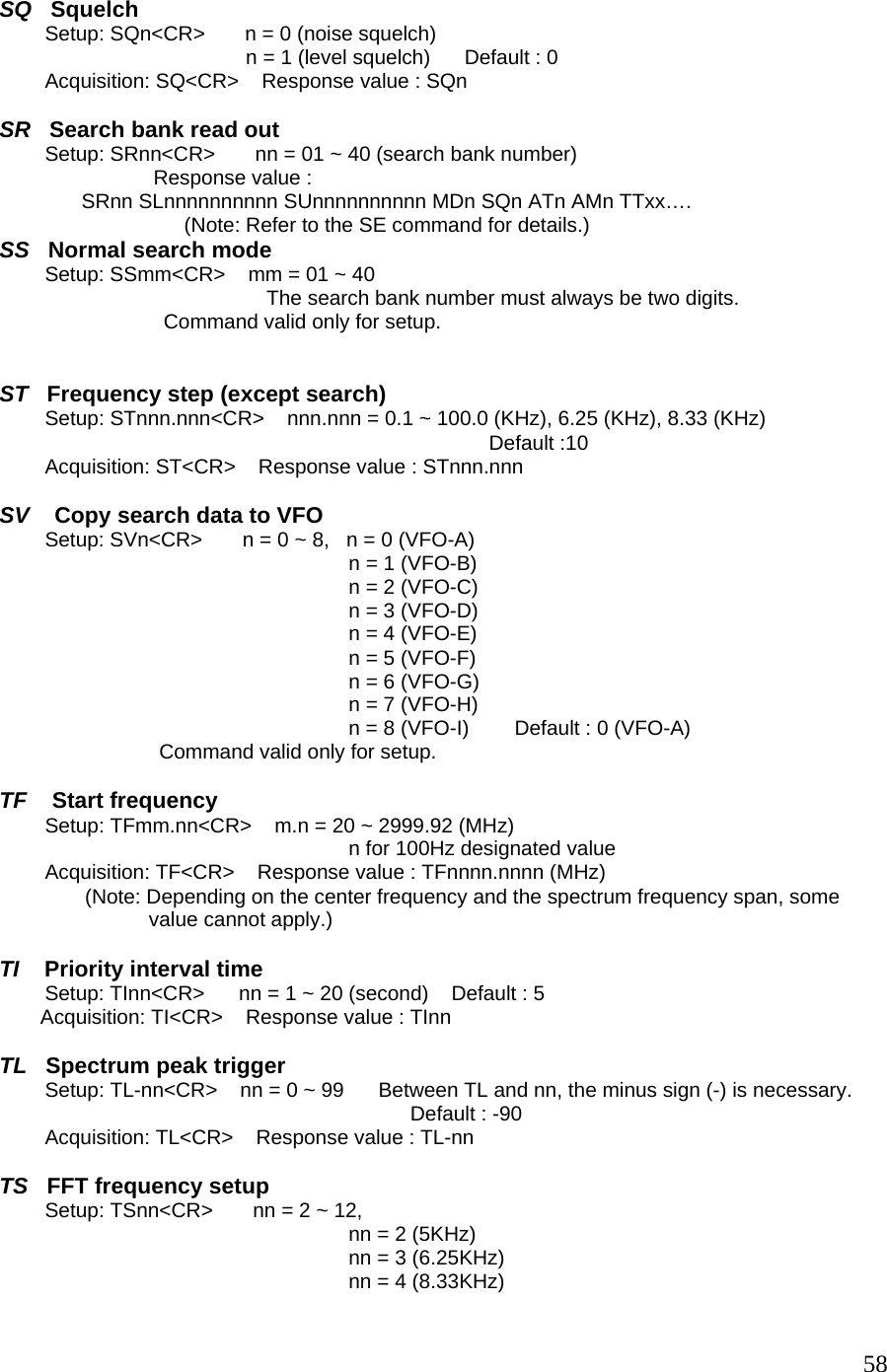
![1 Introduction 1-1 Introduction Thank you for purchasing the SR2000A Frequency Monitor. The SR2000A is a worthy successor to the SR2000 and is the “next generation” in frequency monitor. Using a five-inch TFT color display, DSP (Digital Signal Processing) and FFT (Fast Fourier Transform), faster sampling rates and color imaging, video display function, optional APCO25 (P25) decoder, the SR2000A opens the door to new possibilities and applications. We put the power of FFT algorithms to work in tandem with a powerful receiver covering 25 MHz ~ 3 GHz continuous (Cellular blocked for US consumer version). The result is a compact color spectrum display monitor that’s ultra-sensitive, incredibly fast, yet easy to use. The SR2000A is perfect for base, mobile or field use and can also be used in combination with a personal computer. Every effort has been made to make this manual correct and up to date. Due to continuous development of the product and by error or omission, anomalies may be found and this is acknowledged. © This manual is protected by copyright AOR, LTD. 2007. No information contained in this manual may be copied or transferred by any means without the prior written consent of AOR, LTD. AOR and the AOR logo are trademarks of AOR, LTD. All other trademarks and names are acknowledged. 1-2 Maintaining the unit There are no internal operator adjustments. In the unlikely event of service being required, please contact your dealer for technical assistance. Level of risk As the SR2000A is powered from 12V DC, there is little chance of serious injury as long as common sense is applied. Observe the polarity of connections if supplied AC power units is not being used. DC input is a nominal 12V DC, with the connector wired center conductor positive. Reverse polarity connection will damage the SR2000A and could lead to the risk of fire or explosion under severe circumstances. Carefully handle the AC plug of the supplied AC power unit to prevent touching the terminals when inserting or removing from the AC plug. NEVER connect the SR2000A directly to the AC outlet. Handling the SR2000A Use a soft, dry cloth to gently wipe the SR2000A clean. Never use abrasive cleaners or organic solvents which may damage certain parts. Treat the unit with care, avoid spillage or leakage of liquids into the cabinet and power supply. Special care should be taken to avoid liquid entering around the keys, main dial or via the connectors. [Note: Never push or knock the LCD screen – it is very fragile and sensitive to shock.] Special remarks Do not use or leave the SR2000A in direct sunlight (especially the TFT display). It is best to avoid locations where excessive heat, humidity, dust and vibration are expected. Always keep the SR2000A free from dust and moisture. 3](https://usermanual.wiki/AOR-USA/SR2000A/User-Guide-938963-Page-4.png)
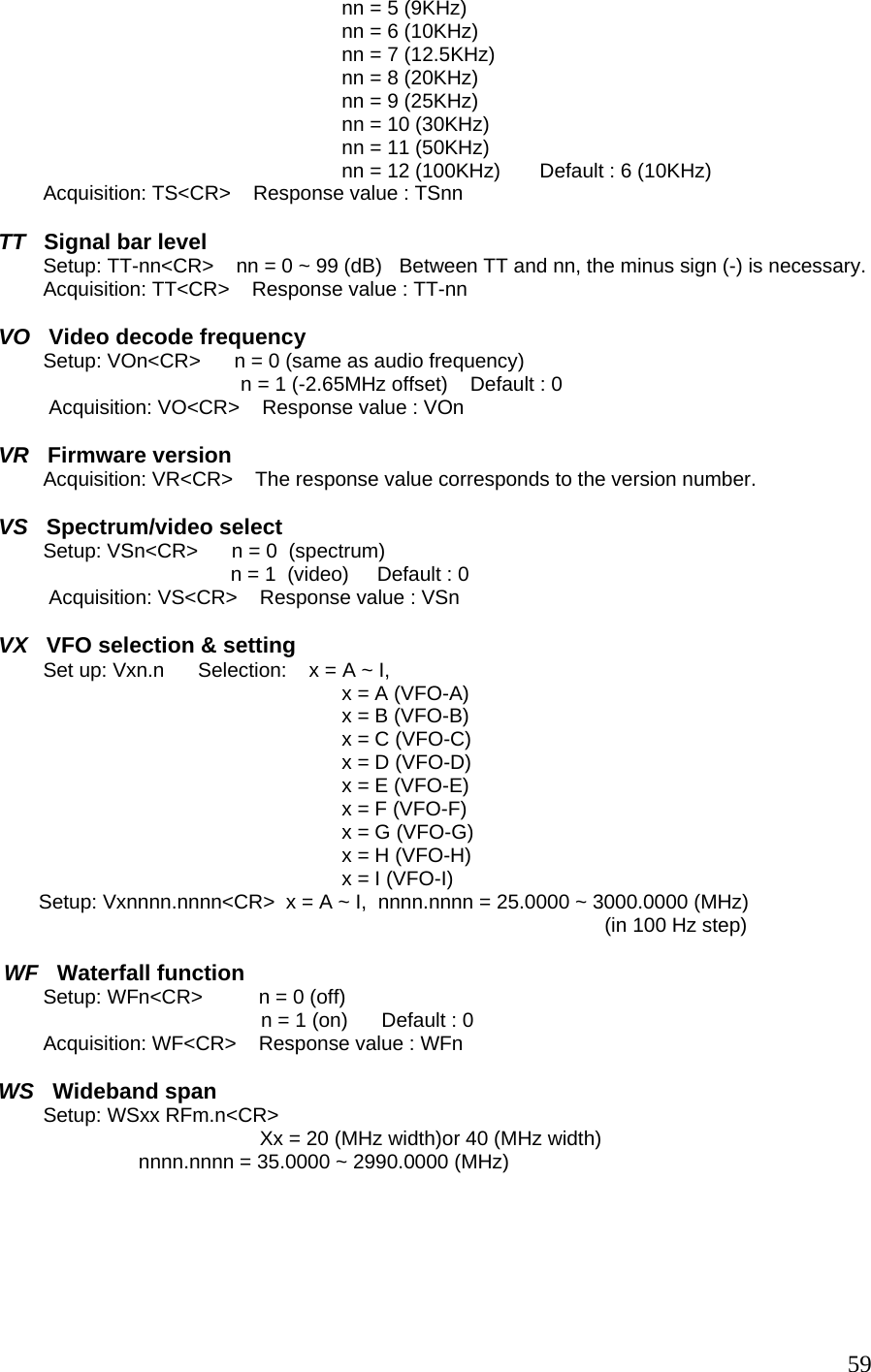
![1-3 Power requirements The SR2000A may be provided with a suitable AC/DC power unit. The SR2000A is designed for operation from a nominal 12 V DC regulated power supply (12 to 14 V is acceptable), which should be capable of supplying a minimum of 1.5 amp continuous, ideally a 2 amp power supply unit should be used. [Note: Never connect the SR2000A directly to an AC outlet.] [Safety Notice: Always disconnect the power supply from the AC outlet when not in use.] Should the SR2000A appear to behave strangely, normal operation may be resumed by resetting the microprocessor. Please refer to section “6. Configuration” for further information. 1-4 Supplied accessories The following accessories are provided in the shipping box. 1 Instruction manual (this booklet) 1 AC adapter 1-5 Features z FFT (Fast Fourier Transform) high speed display The FFT search function enables incredibly high speed signal monitoring, 10MHz search in approximately 0.07 seconds! z Displays up to 40MHz of spectrum bandwidth Up to 40 MHz of bandwidth can be displayed in real time through advanced Digital Signal Processing. (No audio is available when the frequency span is set to 20MHz or 40 MHz) z 5 inch TFT color LCD display 5 inch TFT color display is easy to monitor the clear, crisp images of received signals. z Waterfall (time) display function Tracks signals over time and uses colors to define their strength. z Average or peak value readings z Frequency coverage 25 MHz ~ 3 GHz (Cellular Blocked for US consumer version) z Ultra-stable, high sensitivity triple conversion receiver z AM/NFM/WFM/SFM receive modes z Video display mode (NTSC, PAL, and SECAM format) z 1000 memory settings 100ch x 10 memory banks z Easy menu-driven operation z PC control through serial port or USB interface z APCO25 (P25) decoder (Optional decoder board required) 4](https://usermanual.wiki/AOR-USA/SR2000A/User-Guide-938963-Page-5.png)

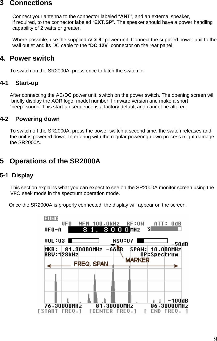
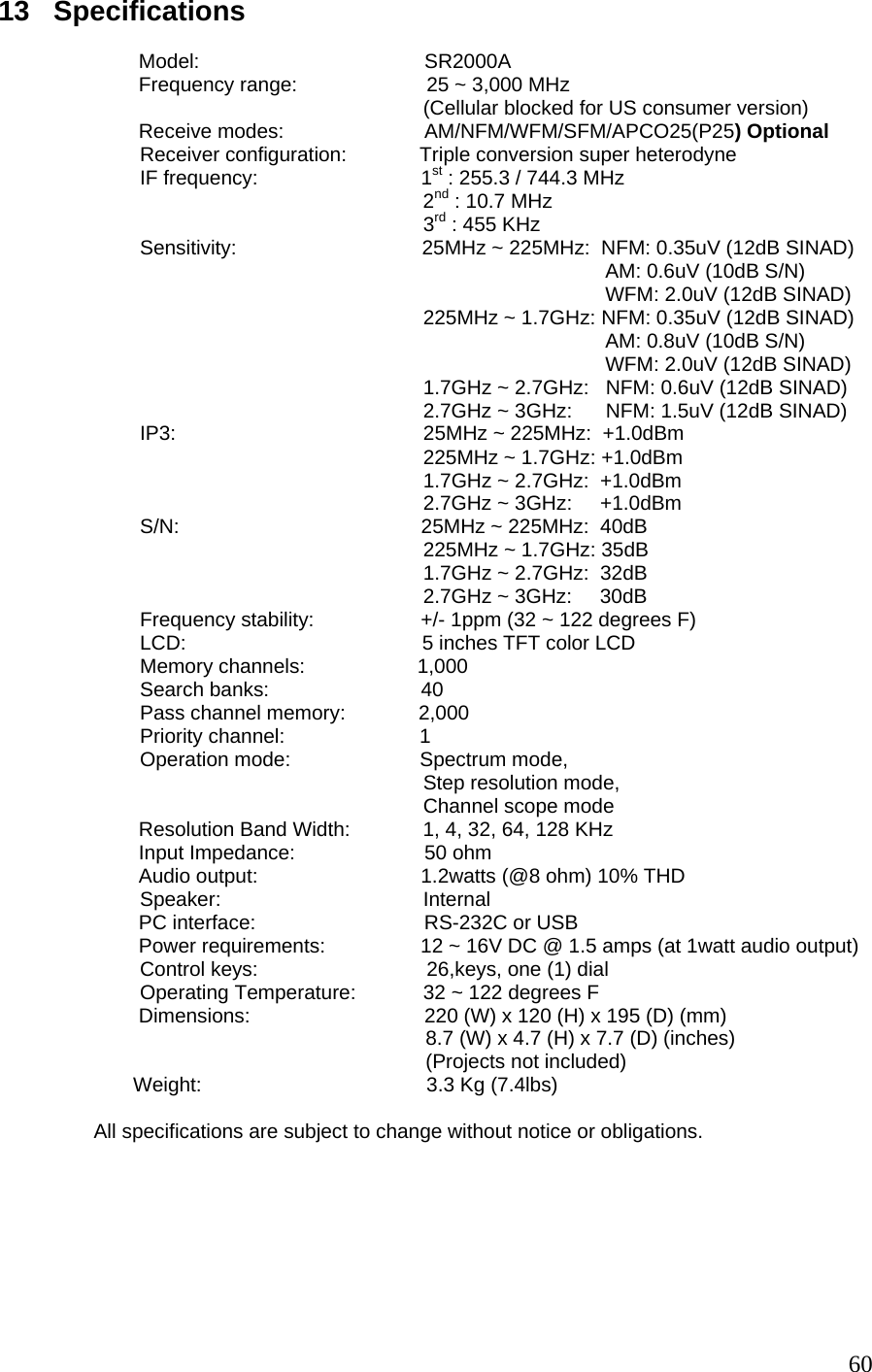
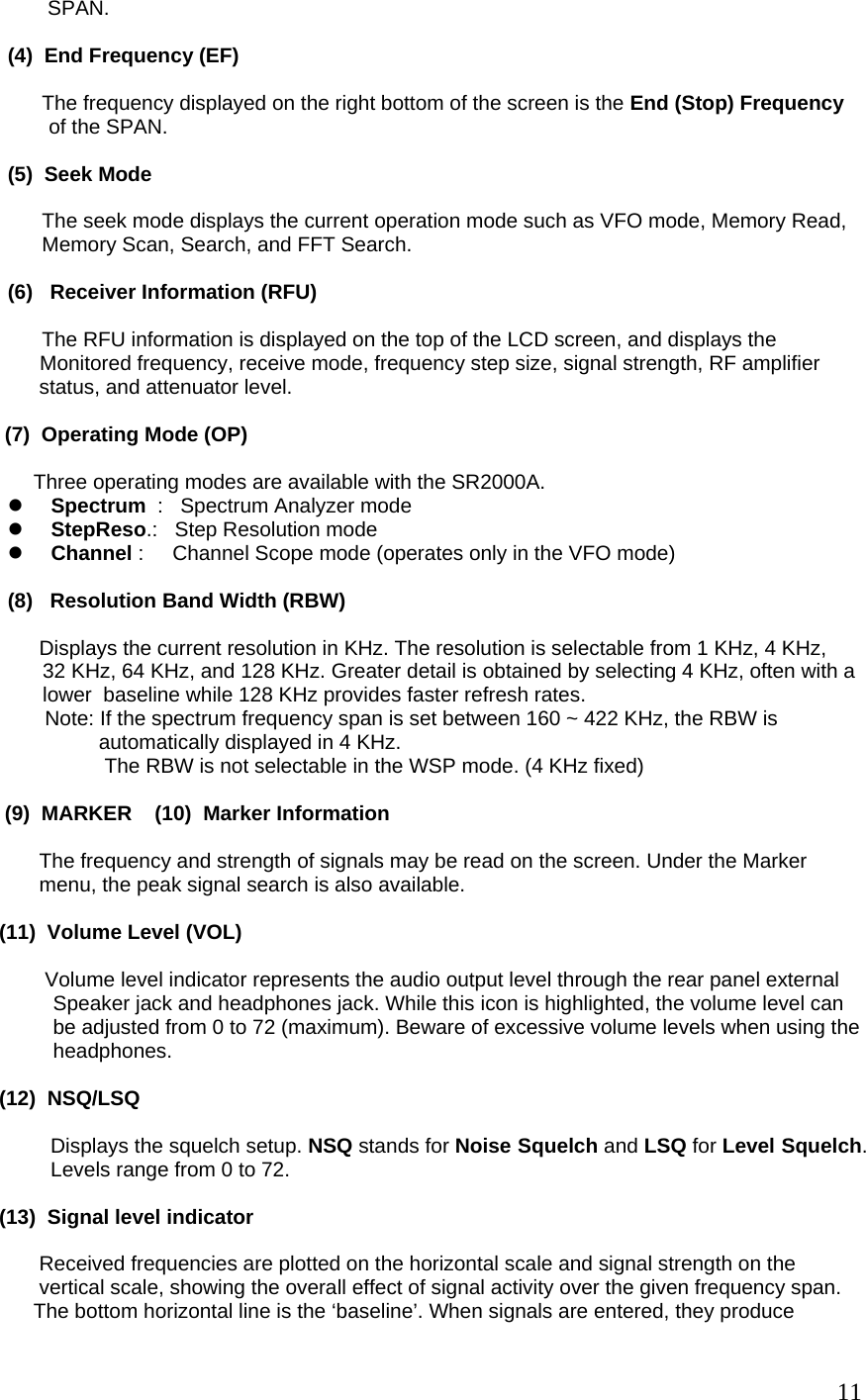
![(1) Center Frequency (CF) The center frequency reading is shown in MHz, and the highest resolution is 10 Hz. (2) Total displayed bandwidth (SPAN) The center frequency appears in the middle of the display with the frequency extending to the left and right. The total frequency spread from the left through center to the right is referred as the total SPAN. The maximum is 10MHz and minimum is 0.160MHz (160KHz) in normal span mode. The horizontal scale is divided into 320 increments (steps). WSP (Wide Span Mode) The SR2000A displays up to 40 MHz of spectrum bandwidth (20MHz or 40MHz selectable) in the wide span mode. To select the wide span mode, set the SR2000A to the VFO mode. Then press the FUNC key. A soft key menu will appear on the bottom of the LCD. [WSP 20M] [WSP 40M] [Video] On this screen menu, choose either the WSP 20M (Span width 20MHz) mode or the WSP 40M (Span width 40 MHz) mode. To return to the normal span mode, press the FUNC key again. A soft key menu will be changed. [to VFO] [WSP 40M] [Video] Press the to VFO soft key. The center frequency in the WSP mode is transferred to the VFO mode screen. Or, press the FUNC key, then press the 4 (VFO) key. The center frequency previously used in the VFO mode will be recalled. (No audio is available when the frequency span is set to 20MHz or 40 MHz) (3) Start Frequency (SF) The frequency displayed at the bottom left of the screen is the Start Frequency of the 10](https://usermanual.wiki/AOR-USA/SR2000A/User-Guide-938963-Page-11.png)
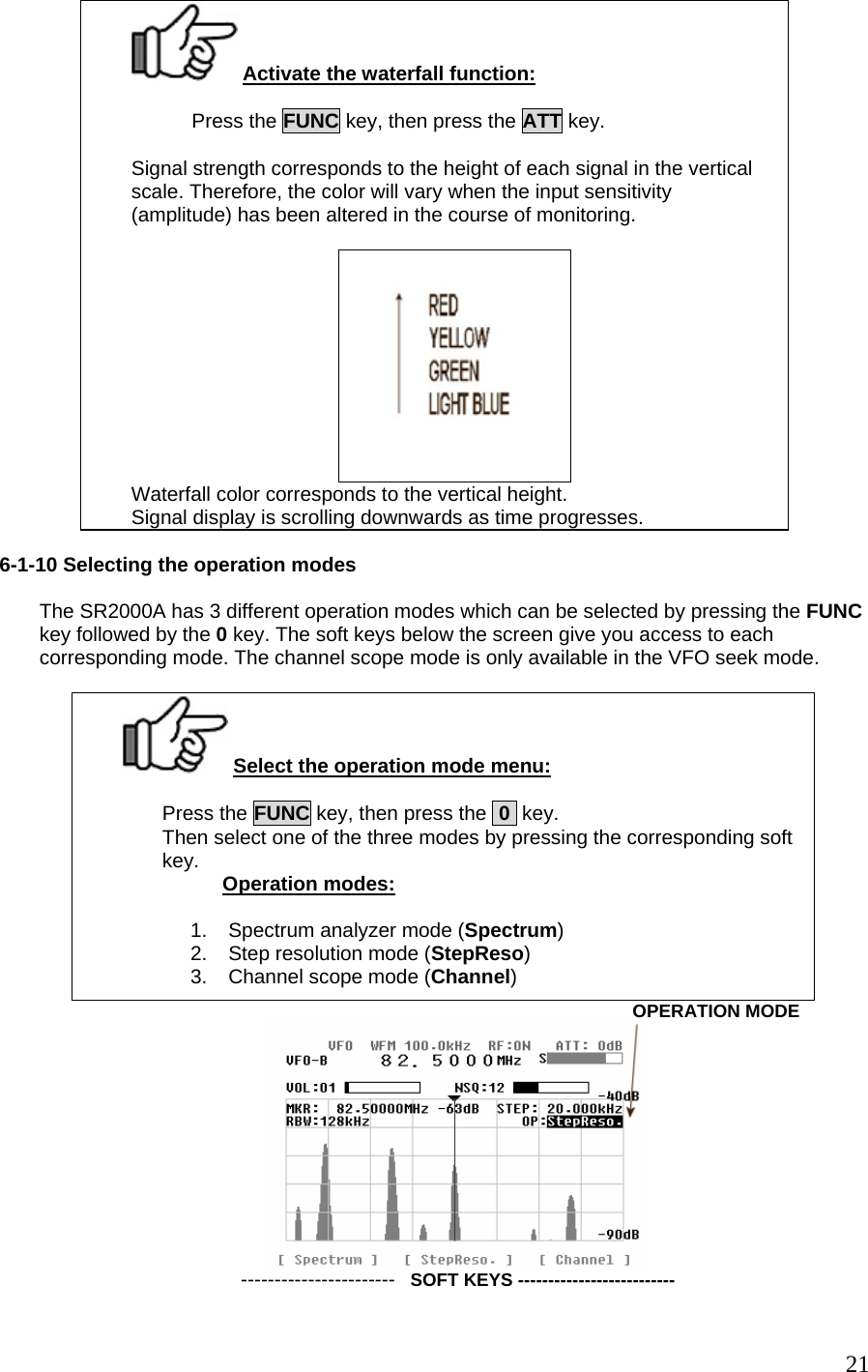
![vertical lines, and the higher the line, the stronger the signal. A 50 dB range is provided by the scale which is divided into 10 dB increments. The vertical scale is adjustable in six levels by altering the internal amplifier (amplitude). The horizontal scale is split into ten segments indicating the frequency span (bandwidth) in use. The marker is designed to move across one segment by one full rotation of the dial knob. (14) Function Key Indicator When the function key is pressed followed by certain keys, they serve a secondary function. The secondary function is printed above the respective key. While the function key is pressed, the reversed FUNC icon appears on the top left corner of the screen. (15) VFO (Variable Frequency Oscillator) The SR2000A has a nine (9) VFO system, identified from VFO-A to VFO-I. Displayed on the previous page example is VFO-A. Note: Relationship between Frequency Span and Frequency Step The LCD provides a high resolution of 320 steps from the left to right edges of the screen X-axis. A frequency bandwidth represented by one step is calculated as SPAN/320. This is done automatically by the SR2000A in the Spectrum Analyzer and Step Resolution Modes. This bandwidth differs from the frequency step size displayed in the Receiver Information (RFU). Resolution Bandwidth (RBW) The resolution is selectable from 1 KHz, 4 KHz, 32 KHz, 64 KHz, and 128 KHz. Greater detail is obtained by selecting 1 KHz, often with a lower baseline while 128 KHz provides faster refresh rates. 5-2 Key Commands The SR2000A allows user-friendly operation through 20 main keys, 3 basic operation keys and 3 soft keys. The selected functions are displayed on the LCD screen. The table below describes the functions allocated to each of the main keys and the basic operation keys. KEYS FUNCTIONS 1~9, 0 , . (period) As entered FUNC+1 [FFT] FFT Search FUNC+2 [SRCH] search mode FUNC+2 (press & hold) [SRCH] search bank input, settings FUNC+3 [SCAN] memory channel mode, memory scan FUCN+3 (press & hold) [SCAN] memory channel input, settings FUNC+4 [VFO] VFO mode, VFO switch FUNC+5 [S SCAN] select scan FUNC+6 [S SET] select memory set FUNC+7 [PRIO] monitoring priorities FUNC+7 (press & hold) [PRIO] monitoring priorities settings FUNC+8 [DEL] deletion of memory channels and search banks FUNC+9 [CONFIG] SR2000A’s overall configuration FUNC+. (period) [OFFSET] monitoring offset settings FUNC+. (period)(press & hold) [OFFSET] frequency settings FUNC+0 [OBS] operation mode selection MODE [MODE] receiving mode selection 12](https://usermanual.wiki/AOR-USA/SR2000A/User-Guide-938963-Page-13.png)
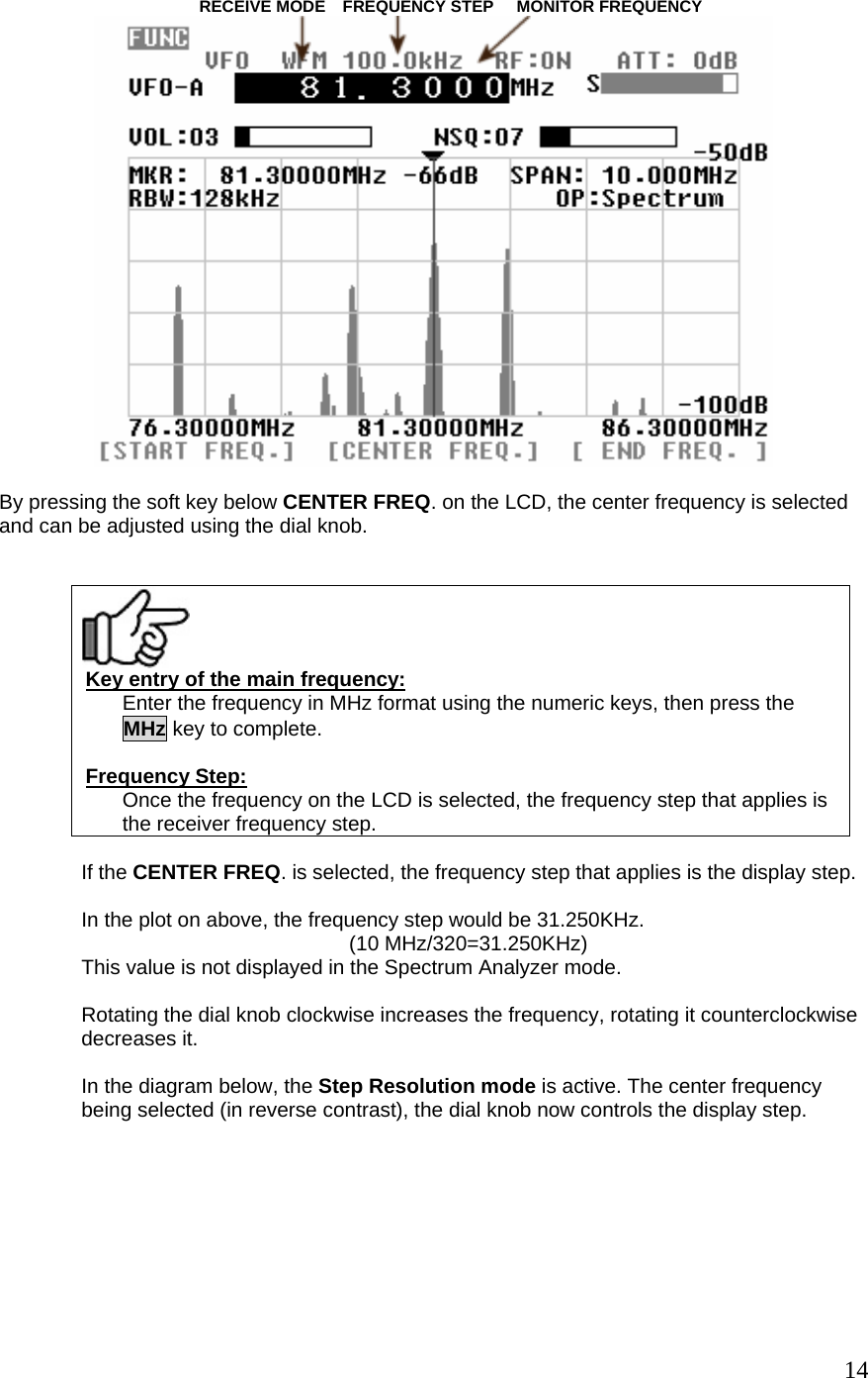
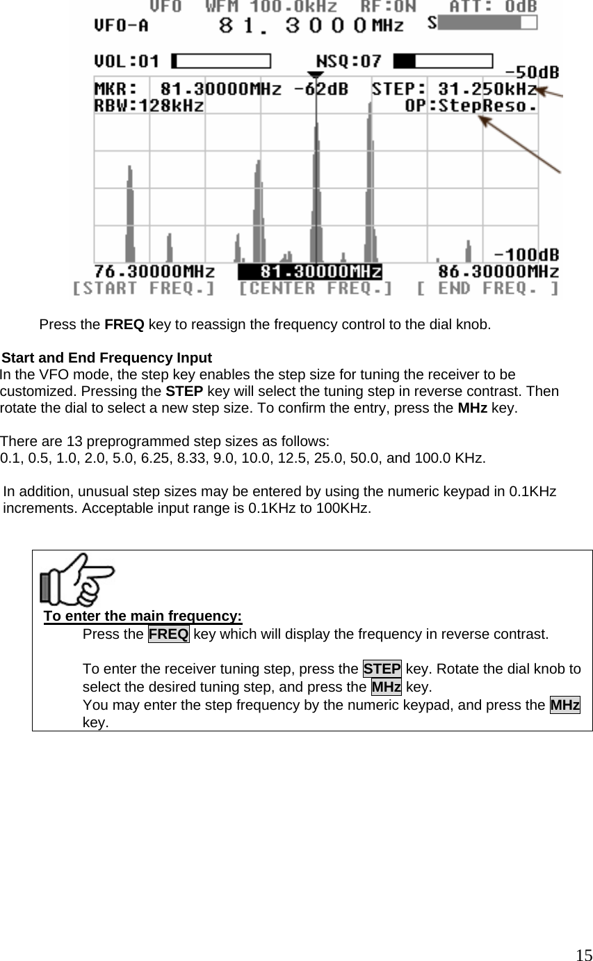
![FUNC+MODE [PASS] pass frequency settings FUNC+MODE (press & hold) [PASS] pass frequency browser STEP [STEP] step frequency settings FUNC+STEP [SPN/STP] frequency span, frequency step settings ATT (press and hold) [ATT] attenuator settings on/off FUNC+ATT [WATER] waterfall display RBW [RBW] resolution bandwidth input FUNC+RBW [OPE] calculation function CLR [CLR] clear, back space key FUNC+CLR [A CLR] all clear, erase a sequence MK.F [MK.F] marker selection, CF settings FUNC+MK.F [MKR] marker mode selection KHz [KHz] to validate in KHz FUNC+ KHz [AMP] amplifier settings MHz [MHz] to validate in MHz, “enter” key MHz (press & hold) Input in memory channel VOL/MUTE Select the dial as a volume knob VOL/MUTE (press & hold) Mute the audio FUNC+ VOL/MUTE Mute the audio SQUELCH / MONI Select the dial as a squelch knob SQUELCH / MONI (press & hold) Open the squelch FUNC + SQUELCH / MONI Open the squelch FREQ. / MKR Select the dial as a frequency tuning knob FREQ. / MKR (press & hold) Select the dial as a marker tuning knob FUNC+WSP 20M (Soft key) Select 20MHz of spectrum bandwidth FUNC+WSP 40M (Soft key) Select 40MHz of spectrum bandwidth FUNC+ Video (Soft key) Select the video display mode 6 Monitoring Modes 6-1 Basic operations – VFO mode (manual mode) This describes the SR2000A in the most commonly used VFO mode. This mode allows manual input of the center frequency. 6-1-1 Setting up the monitoring frequency The SR2000A follows the rule: Monitor main frequency (MF) = Center Frequency (CF) In the Spectrum Analyzer or Step Resolution modes, you can enter the frequency directly through the numeric keypad, followed by the MHz key to complete the sequence. In addition, the receiver may be tuned using the dial knob. In the plot below (with the frequency selected in reverse contrast), the frequency step size that applies the receiver frequency step. 13](https://usermanual.wiki/AOR-USA/SR2000A/User-Guide-938963-Page-14.png)
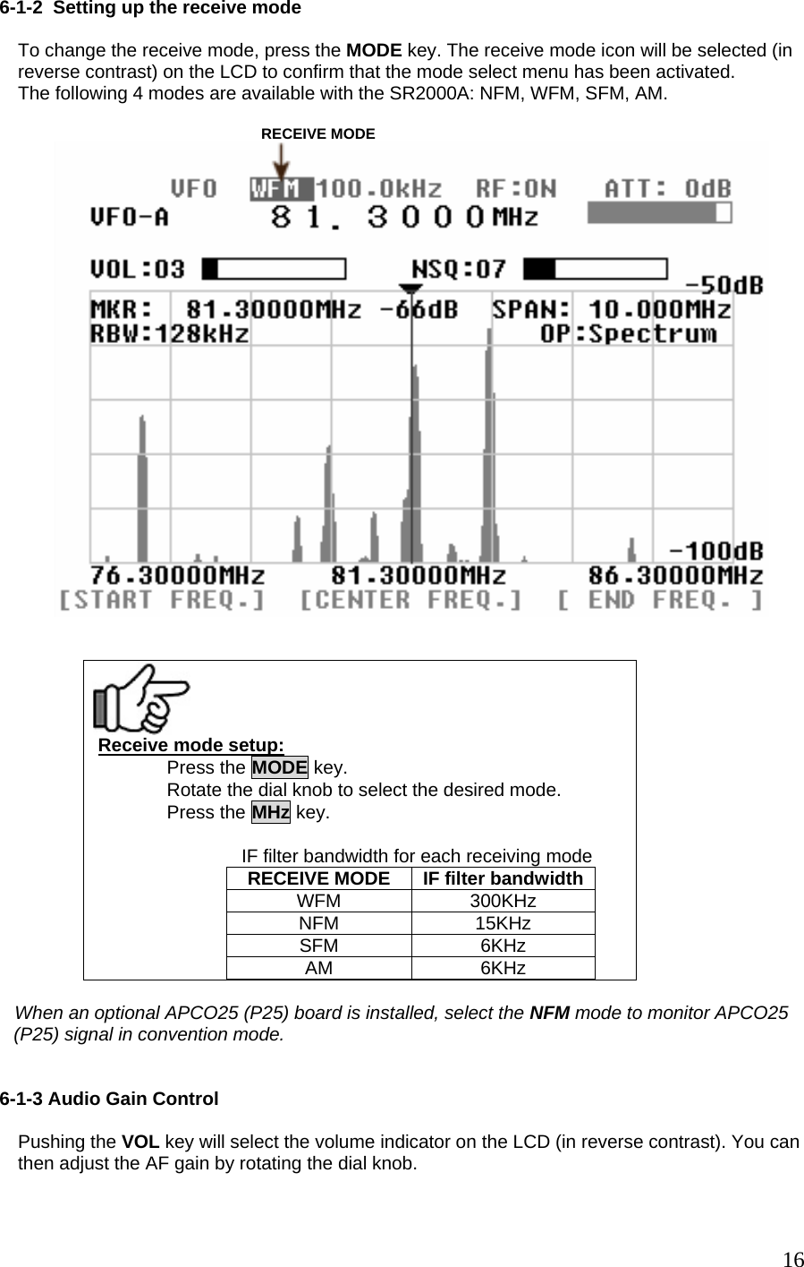
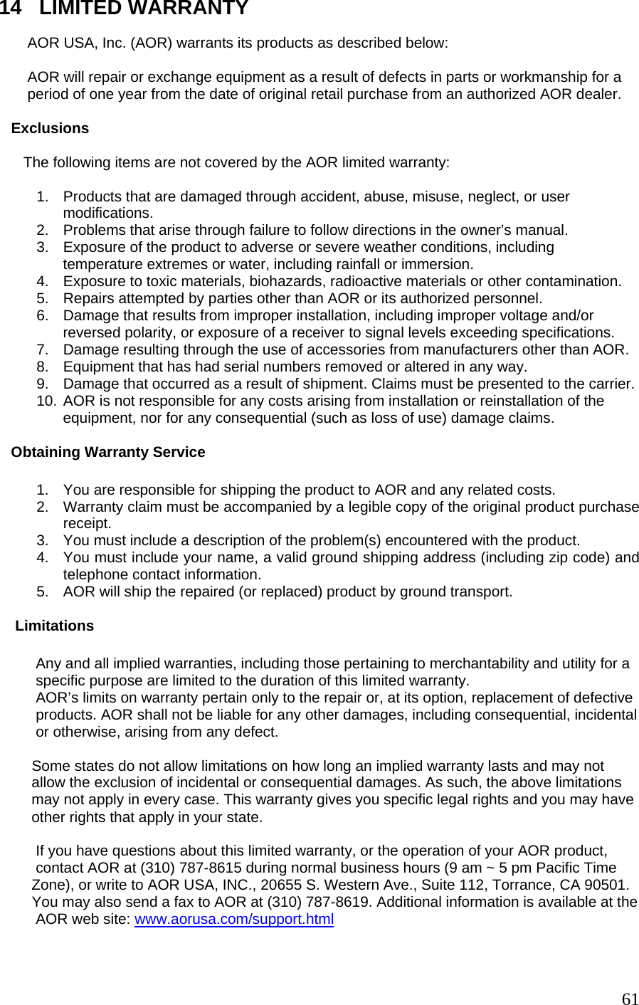
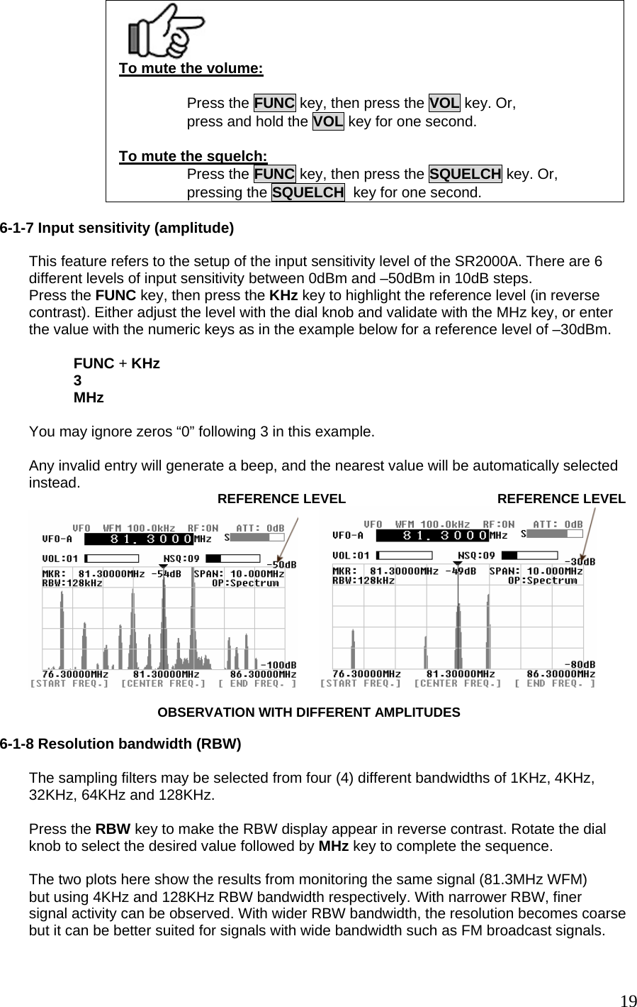
![VOLUME LEVEL VOLUME INDICATOR AF gain (volume level) control: Press the VOLUME key. Rotate the dial knob to select the desired volume level. The volume level can be set from level 00 to 72. To mute he sound, press the FUNC key, then press the VOL key. (Press and hold the VOL key for one second to do the same.) To undo the mute, repeat the above steps. 6-1-4 Squelch control The SR2000A has two (2) squelch types, NSQ (Noise Squelch) and LSQ (Level Squelch). Pressing the SQUELCH key allows you to select one or the other. Then adjust the squelch level with the dial knob, from level 00 to 72. ÅÆ NSQ selected LSQ selected Note In both squelch modes, an “S” icon appears on the left side of the S-meter when the squelch Is open. [Note] When LSQ is selected, a white line under the S-meter represents the squelch level compared to signal strength. 17](https://usermanual.wiki/AOR-USA/SR2000A/User-Guide-938963-Page-18.png)


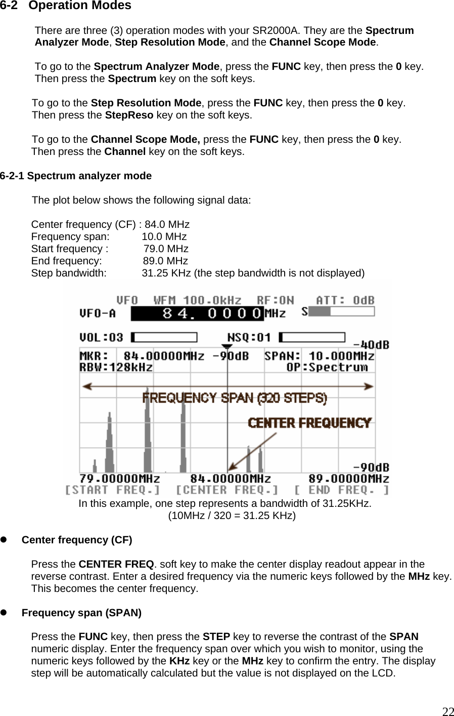
![z Start and End frequencies The START and End frequency can be entered in the same manner as the center frequency entry using the assigned soft keys, numeric keys and MHz key. The dial knob is not valid for the entry. [Note] The CF = MF principle In the spectrum analyzer mode and the step resolution mode, Main frequency = Center frequency When the center frequency is altered using the numeric keys or the dial knob, the main frequency is changed accordingly. The center frequency becomes the main frequency. Step bandwidth In the spectrum analyzer mode, the bandwidth value per step is not displayed on the LCD. Displayed frequency span (MHz) is obtained by the following formula: CF +/- (frequency span / 2) In the above example, the center frequency is 84.0 MHz. Therefore, the display frequency span is 84 +/- (10 /2) = 84 MHz +/- 5 MHz. 6-2-2 Step resolution mode The plot below shows the following signal data: Center frequency (CF) : 122.50 MHz Step bandwidth: 25.0 KHz Start frequency : 118.5 MHz End frequency: 126.5 MHz Frequency span: 8 MHz The frequency span value is automatically calculated by the display step. However, it does not appear on the screen. In this example, the chosen step is 25 KHz, the frequency span is 25 KHz x 320 = 8 MHz. 23](https://usermanual.wiki/AOR-USA/SR2000A/User-Guide-938963-Page-24.png)
![[Note] When the center frequency (CF) is selected and controlled with the dial knob, the monitor main frequency (MF) stays the same on display. In this case, MF is NOT equal to CF. Effective frequency coverage The center frequency (CF) must be within the frequency coverage of the SR2000A (25MHz ~3000MHz). If exceeded, monitoring is not possible. Display frequency span (MHz) is obtained by the following formula: CF +/- (display step x 160) In the above example, the center frequency is 122.50MHz. Therefore, 122.5 +/- (25 x 160) = 122.5MHz +/- 4 MHz 6-2-3 Channel scope mode The plot below shows the following signal data: Start frequency : 82.0 MHz Display step : 20.0 KHz End frequency : 85.2 MHz Frequency span : 3.2 MHz Main frequency marker : 84.0 MHz In this mode, neither the frequency span nor the center frequency values appear on the screen. z Start frequency (Ch. START) Press the CH. START soft key (left key below the LCD) to make the start frequency display appear in reverse contrast. Enter a desired frequency using the numeric keys, which is the lowest of the frequency spread you wish to monitor, followed by the MHz key to confirm. z Step frequency (Ch. STEP) Press the CH. STEP soft key (middle key below the LCD) to make the frequency display appear in reverse contrast. Enter the desired step frequency using the numeric keys, followed by the KHz or the MHz key to confirm. 24](https://usermanual.wiki/AOR-USA/SR2000A/User-Guide-938963-Page-25.png)
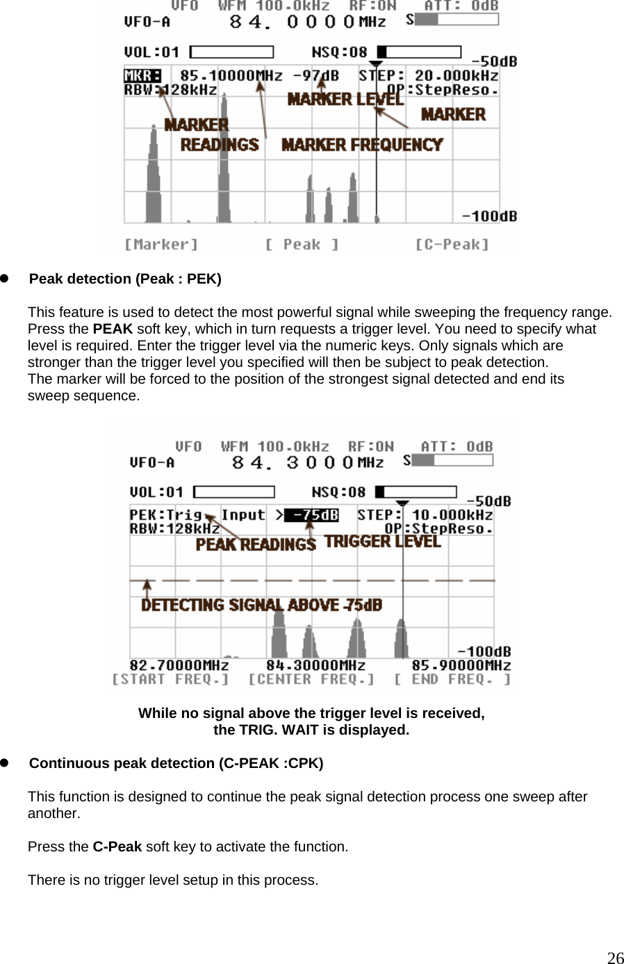
![z End frequency (Ch. END) Press the Ch. END soft key (right key below the LCD) to make the end frequency display appear in reverse contrast. Enter a desired frequency using the numeric keys, which is the highest frequency spread you wish to monitor, followed by the MHz key to confirm. z Marker and main frequency marker operation When the channel scope mode is activated, monitoring begins on the start frequency. Press the FUNC key followed by the FREQ. key and rotate the dial knob to move the white marker onto the signal of your interest, then press the MK.F key. The yellow receive marker moves to the nominated position and the SR2000A monitors the selected frequency. [Note] The channel scope mode functions only in the VFO mode. Moreover, if the VFO is switched, setting information will be lost and the operation mode will change to spectrum analyzer mode The end frequency (Ch. END) is confined by the following formula: (Ch. START) + [(Ch. STEP) x 160] or, (Ch. START) + 5 MHz or, (Ch. START) + > 0.16 MHz For this reason, if you do not enter an end frequency, the SR2000A will automatically select an appropriate end point. Invalid entry for the end frequency will be alerted with a beep and the closest possible valid frequency will be automatically chosen by the SR2000A. The same happens with anyinvalid frequency entry. 6-3 Marker functions The SR2000A has a marker function. The marker is often used to obtain the value of a frequency of interest. In addition to the instantaneous reading, it provides peak detection and continuous peak detection. Press the FUNC key followed by the MK.F key to place the SR2000A in marker mode operation. SOFT KEY ALLOCATIONS IN THE MARKER MODE INSTANTANEOUS PEAK CONTINUOUS READING DETECTION DETECTION The marker function operates in the WSP mode and the memory channel mode (except MK.F mode). z Instantaneous reading (Marker : MKR) This feature is useful for many applications. The marker can be moved sideways by rotating the dial knob. The LCD displays the frequency and signal strength reading where the marker is positioned. 25](https://usermanual.wiki/AOR-USA/SR2000A/User-Guide-938963-Page-26.png)
![[Note] [MK.F] key functions: In the spectrum analyzer and step resolution mode, pressing the MK.F key forces the marker frequency to become the center frequency. In the channel scope mode, pressing the MK.F key will not become the center frequency. The MK.F key cannot be used in the Peak Detection mode. 6-4 Calculation function Pressing the FUNC key followed by the RBW key allows you access to three (3) calculation features: Maximum value hold (MAX), Average value (AVR) and Median (MED) value. Each function is then accessible through the corresponding soft key below the LCD. Note this function is available in the WSP mode and the memory channel mode. z Maximum value hold (MAX) Press the MAX soft key to access this feature, and the MAX icon will be displayed. To exit from this feature, press the FUNC key, then press the RBW key, and press the MAX key. With the MAX function in use, each sweep will be retained as data and build-up until the process ends. This is particularly useful to detect intermittent signals which come and go over a period of time. 27](https://usermanual.wiki/AOR-USA/SR2000A/User-Guide-938963-Page-28.png)
![z Averaged value (AVR range: 2 ~ 31) Press the AVR soft key to access this feature, and the AVR icon will be displayed. You are required to enter a sampling cycle between 2 and 31 to produce averaged results. To exit from this feature, press the FUNC key, then press the RBW key, and press the AVR key. This feature is designed to provide the plot pattern obtained by averaging the signals received over the sampling cycle. A stable signal pattern is produced even if the signal is fluctuating in strength. DISPLAYS AVERAGE VALUE OF 20 z Median (MED range: 2 ~ 4) Press the MED soft key to access this feature, and the MED icon will be displayed. The plot is designed to provide signal pattern based over a sampling cycle of between 2 and 4, and is useful to plot impulse noise. The sampling cycle can be entered via the numeric keys followed by the MHz key. To exit from this feature, press the FUNC key, then press the RBW key, and press the MED key. [Example] Display step : 10 KHz, Median : 2, and a frequency of 50 MHz: 50 MHz – 10 KHz = 49990 KHz 50 MHz + 10 KHz = 50010 KHz The value showed on the dB axis at 50 MHz will be the average of the three values for the 3 frequencies. 6-5 Video monitor function The SR2000A has a built-in video decoder and supports NTSC, PAL, and SECAM format. The video signal format is automatically detected. 28](https://usermanual.wiki/AOR-USA/SR2000A/User-Guide-938963-Page-29.png)
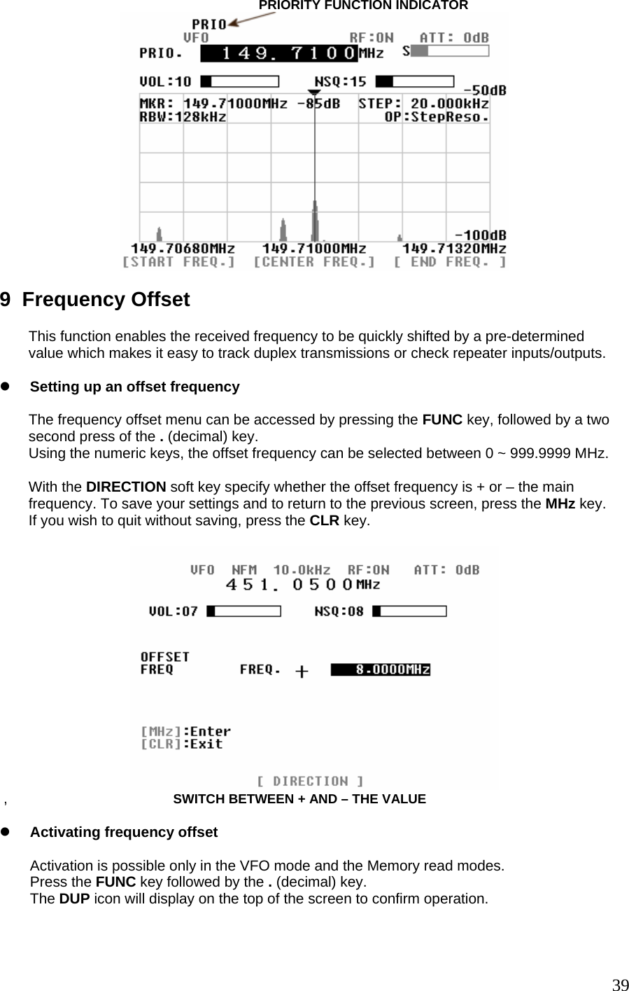
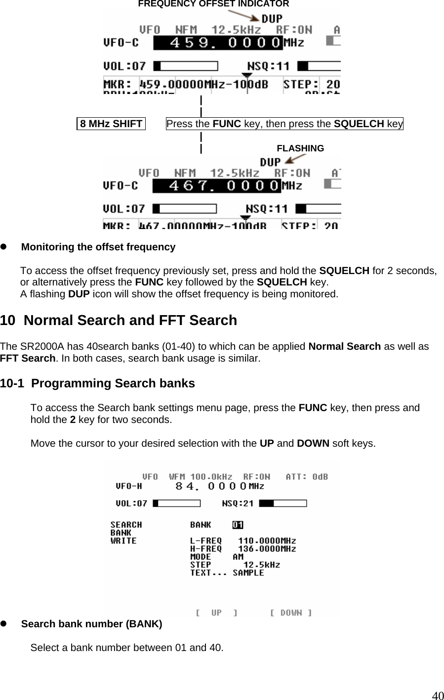
![If the video signal frequency is below 1,000 MHz, then the AM video mode will be automatically selected. If the video signal frequency is above 1,000 MHz, then the FM video mode will be automatically selected. To activate the video function, perform the following steps: 1. In the VFO mode or the spectrum analyzer mode, set the voice frequency of the video signal. 2. Press the FUNC key. 3. A soft key menu will appear on the bottom of the LCD. [WSP 20M] [WSP 40M] [Video] 4. Press the Video soft key. To return to the normal spectrum analyzer screen, push any soft key. [Note] Some video transmitters utilizes the reversed frequency shift modulation in order to set signals scrambled. In this case, the video signal can be descrambled by performing following steps: 1. In the configuration menu (see Chapter 7, Configuration), select the V.FREQ DIR. 2. Select NORMAL or REVERSE to descramble video signal. 7 Configuration In this chapter, we learn how to set fundamental operating parameters of the SR2000A. To access the SR2000A’s configuration menu, press the FUNC key, then press the 9 key. 29](https://usermanual.wiki/AOR-USA/SR2000A/User-Guide-938963-Page-30.png)

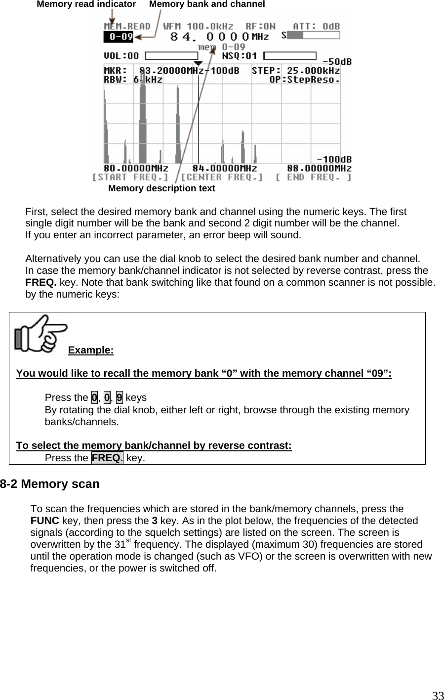
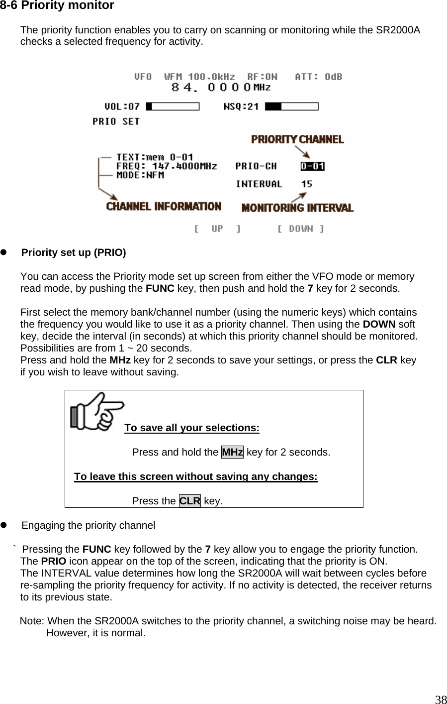
![Four functions as the dial default, to which it returns after a given time. This time in seconds Can be set with the DIAL-TIME selection, anywhere between 1 and 30 seconds. Default DEF-DIAL setting is OFF, the dial retains the functions you have assigned to it. z DATA LINE Select the PC interface port. Default setting is REMOTE 2 (RS-232C). z DATA BPS Used to configure the serial port speed. Following speeds are available: 9600, 19.2k, 38.4k, 57.6k, 115kbps. Default speed is 115kbps. z BACKLIGHT Switches the LCD screen backlight on and off. Caution: Setting the LCD screen to off would render it unreadable, therefore, it is highly advised to maintain the default in the ON position. The OFF feature is for professional use of the SR2000A. [Note]: While accessing the SR2000A configuration menu, the only receiving functions that can be altered are the AF GAIN (volume) and SQUELCH. To return to the configuration menu, press the FREQ. key, 7-1 Resetting the SR2000A If you wish the SR2000A to return to the factory default settings, perform the following steps: 1. Turn the SR2000A power off. 2. Press and hold the [ 3 ] key and [ 6 ] key simultaneously while turning the power on. 3. After the LCD displays several flashing, then release the [ 3 ] key and the [ 6 ] key. 8 Memory Channels The SR2000A features 1000 memory channels (100 channels in each of the 10 banks). Press the FUNC key, then press the 3 key to access the “Memory read” mode. To access the memory read mode: Press the FUNC key and then press the 3 key. 8-1 Memory read mode Once you enter the “memory read” mode, the screen looks like the plot below. Be aware that you cannot enter this mode unless at least one frequency has previously been stored as a memory channel. (As described in paragraph 8-3). 32](https://usermanual.wiki/AOR-USA/SR2000A/User-Guide-938963-Page-33.png)
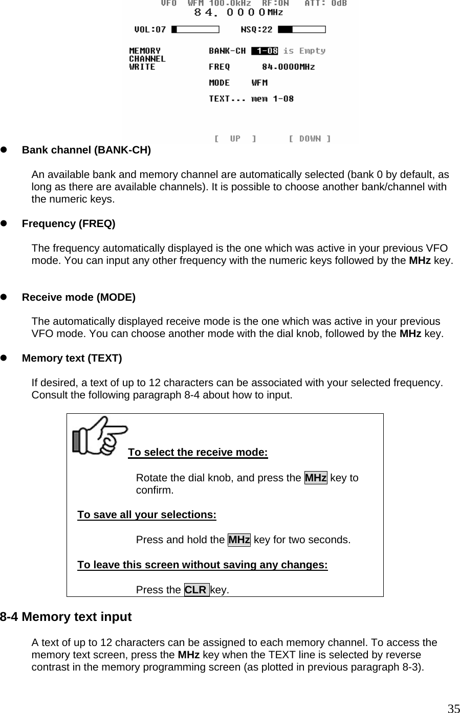
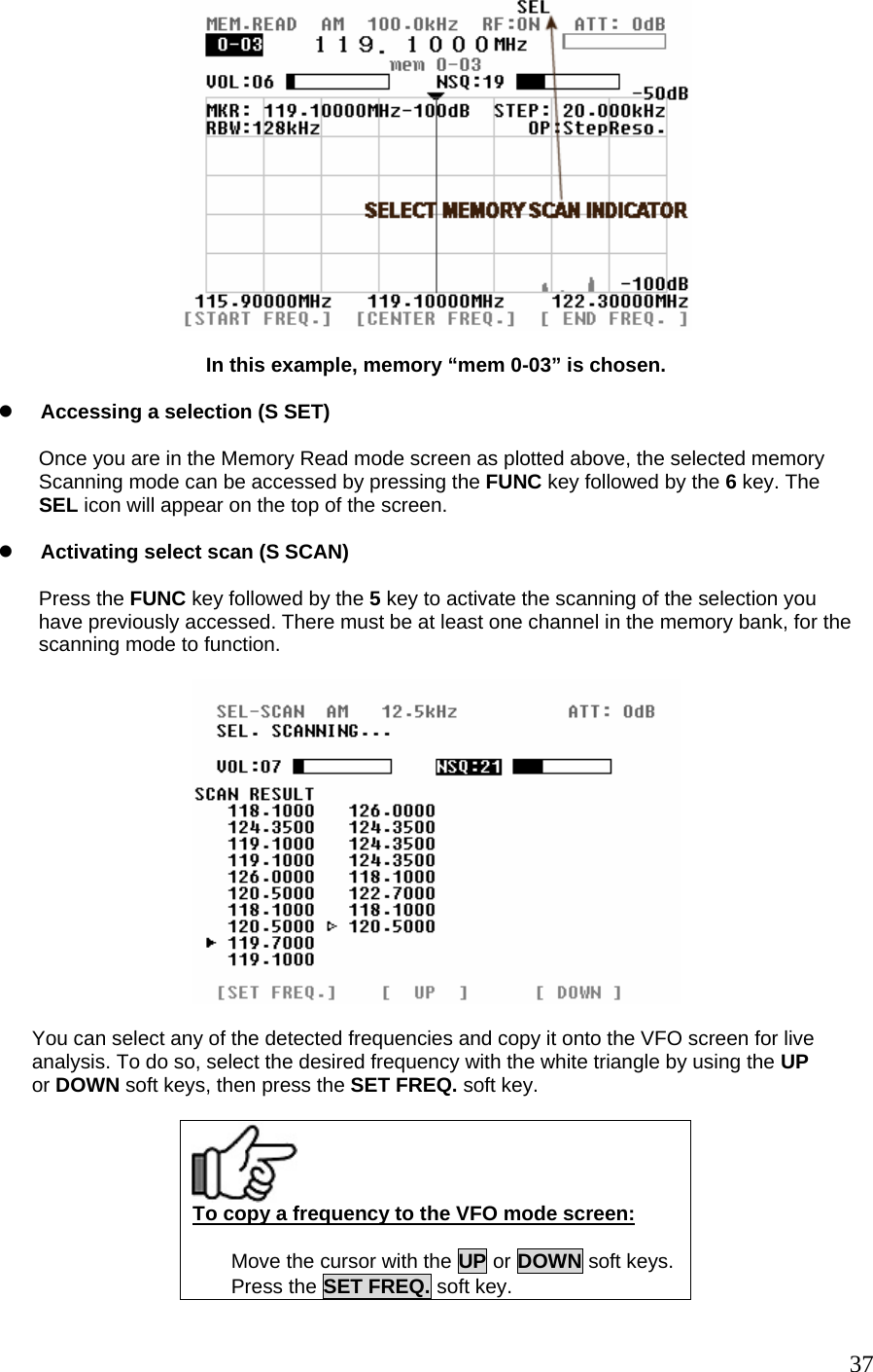
![SELECTED LETTER Up To 12 CHARACTERS CAN BE ENTERED HERE z Soft keys (<=, DEL, = =>) The soft keys <= = and = => allow you to go to the previous/next character, while DEL soft key deletes the selected character. z Character input A set of character is assigned to each numeric keys, as displayed on the monitor. For example, when you press the 2 key, the assigned characters come as follows: A Æ B Æ C Æ a Æ b Æ cÆ 2 Æ A Æ ….. When a different key is pressed, the cursor goes automatically to the next character. [Note]: The text input method of the SR2000A is very similar to cellular phones. z Saving your changes To save your text input, press the MHz key, which will bring you to the Memory Programming Page (previous paragraph 8-3). Remember to press and hold the MHz key again for 2 seconds to save all your changes. To save your text input: Press the MHz key. To leave this screen without saving any changes: Press and hold the CLR key for 2 seconds. 8-5 Selected memory scanning The Selected Memory Scanning function allows you to scan only a selection of frequencies which were previously saved as memory channels. A maximum of 100 channels within a bank can be scanned. 36](https://usermanual.wiki/AOR-USA/SR2000A/User-Guide-938963-Page-37.png)
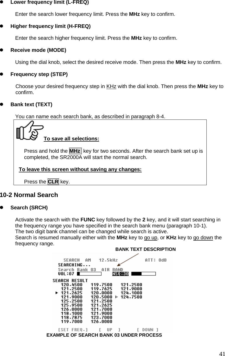
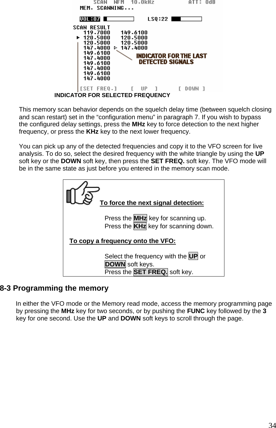
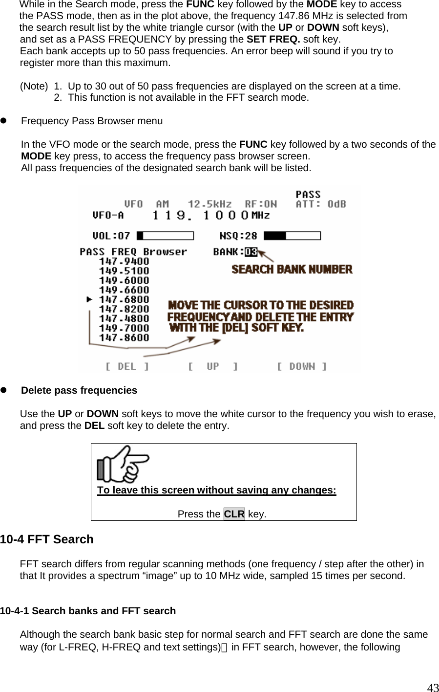
![z Nonstop search If you press again the FUNC key and 2 keys while the search is active (as plotted above), You will enter the Nonstop search mode. The SR2000A will continuously search in the frequency range you have specified. You can exit that mode by repeating the same steps. As the screen can only display 30 frequencies on the screen, new frequencies will overwrite the older ones. NONSTOP (CONTINUOUS) SEARCH You can pick up any of the detected frequencies and to the VFO screen for live analysis. To do so, select the desired frequency with the white triangle by using the UP and DOWN soft keys, then press the SET FREQ. soft key. To copy a frequency to the VFO screen: Move the cursor with the UP or DOWN soft keys. Press the SET FREQ. key. 10-3 Frequency Pass setup Frequency Pass allows individual frequencies to be passed so they will be skipped over when in normal search mode (including nonstop search). Each of 40 search banks have 50 pass frequencies for a total of 2000. IF PASS FREQUENCIES ARE PRESENT IN THE SEARCH BANK, THE [PASS] ICON APPEARS. 42](https://usermanual.wiki/AOR-USA/SR2000A/User-Guide-938963-Page-43.png)
![Up to 30 frequencies can be listed on one screen. After that, every following result will overwrite the older ones. z Color coded signal levels As the FFT search operates at high speed, and to render the results more understandable, eight different colors are assigned to different signal intensities. Although this display information is limited to the frequency and signal level colors, the real power of the SR2000A is its possibility to output all these data to a PC interface port in a continuous data stream. [Note] Format of the Interface data output to PC: DL-mm RFnn…. (mm: dB level, nn…..: frequency[Hz]) Please refer to the command list for details. During the FFT search, it is possible to copy any frequency from the search results to the VFO mode, for further analysis. To do so, use the UP or DOWN soft keys to the white triangle cursor to the desired frequency, and press the SET FREQ. key to switch to VFO (you are therefore exiting the FFT search mode). While the FFT search results are being listed on the screen, you can switch banks by entering the two digits bank number (this will bring you to the FFT search setup screen). While the FFT search results are being listed on the screen, by pressing the CLR key you can return to the FFT search setup screen and modify parameters. Validate each change 45](https://usermanual.wiki/AOR-USA/SR2000A/User-Guide-938963-Page-46.png)
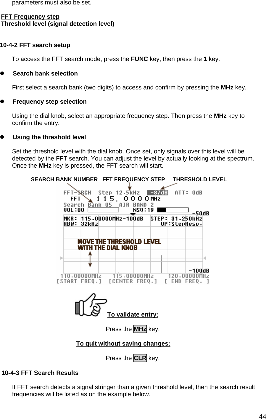
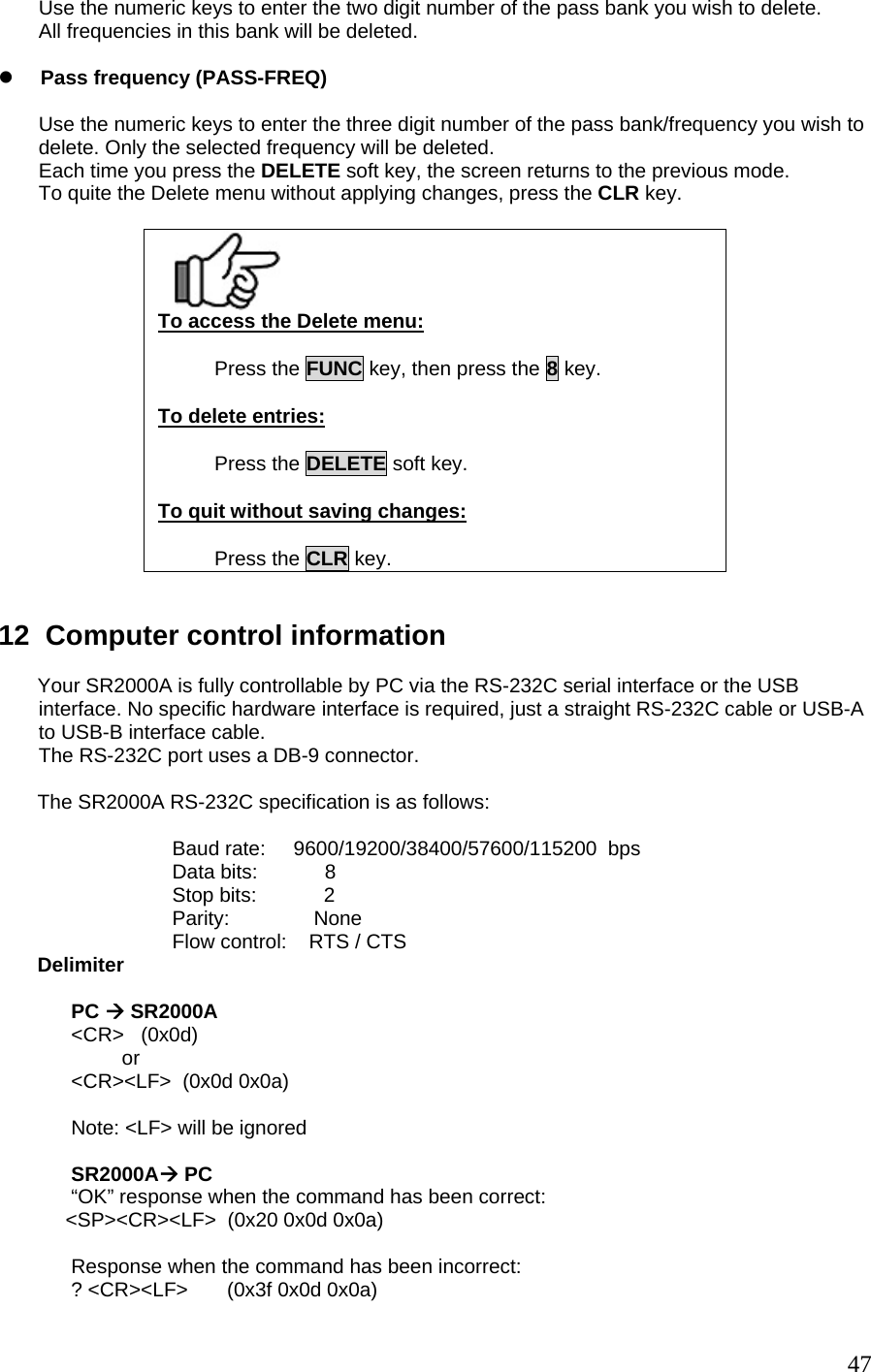
![by pressing the MHz key. [Caution!] When FFT search is operating, the resolution bandwidth (RBW) is automatically set to 4 KHz. 11 Delete menu The SR2000A allows convenient deletion of search banks, memory banks, memory channels, pass banks and pass frequencies in one single Delete menu. To access the Delete menu function, press the FUNC key, then press the 8 key. As in the plot below, move the cursor to the desired selection with the UP or DOWN soft keys, then press the DELETE soft key to delete your selection. THE CONTENTS OF THE PUSH TO DELETE SELECTION ARE DISPLAYED z Search bank (SRCH-BANK) Use the numeric keys to enter the two digit number of the search bank you wish to delete. z Memory bank (MEM-BANK) Use the numeric keys to enter the one digit number of the memory bank you wish to delete. All frequencies in this bank will be deleted. z Memory channel (MEM-CH) Use the numeric keys to enter the three digit of the memory bank/channel you wish to delete. Only the frequency assigned to this channel will be deleted. z Pass bank (PASS-BANK) 46](https://usermanual.wiki/AOR-USA/SR2000A/User-Guide-938963-Page-47.png)
![Response to the read command: Following the output of the parameter, the correct response should read: <SP><CR><LF> (0x20 0x0d 0x0a) Numerical parameter auto-correct The SR2000A correct the numerical command parameter to the digit format applying to the given parameter. In the following example, the DB command has to be followed by a 3 digit number. [Example] The SR2000A will add one or two “0” in order to achieve three digits. DB3<CR> ----- processed as DB003<CR> DB03<CR> ---- processed as DB003<CR> However be aware that for some commands like Memory channel or Search bank, if You input MQ33 for MQ303 (bank 3, channel 3), the SR2000A would mistakenly correct your entry to MQ033 which means bank 0, channel 33. Format of the data output to PC at search and scan: FFT search DL-mm RFnn… Mm: dB level, nn… : frequency [Hz] Before “mm” be sure to add “-“ (minus) Normal search and scan ATn AMn SQn LCxxx RFmmmmnnnnn Refer to AT, AM, SQ, LC, RF commnds for detail 48](https://usermanual.wiki/AOR-USA/SR2000A/User-Guide-938963-Page-49.png)