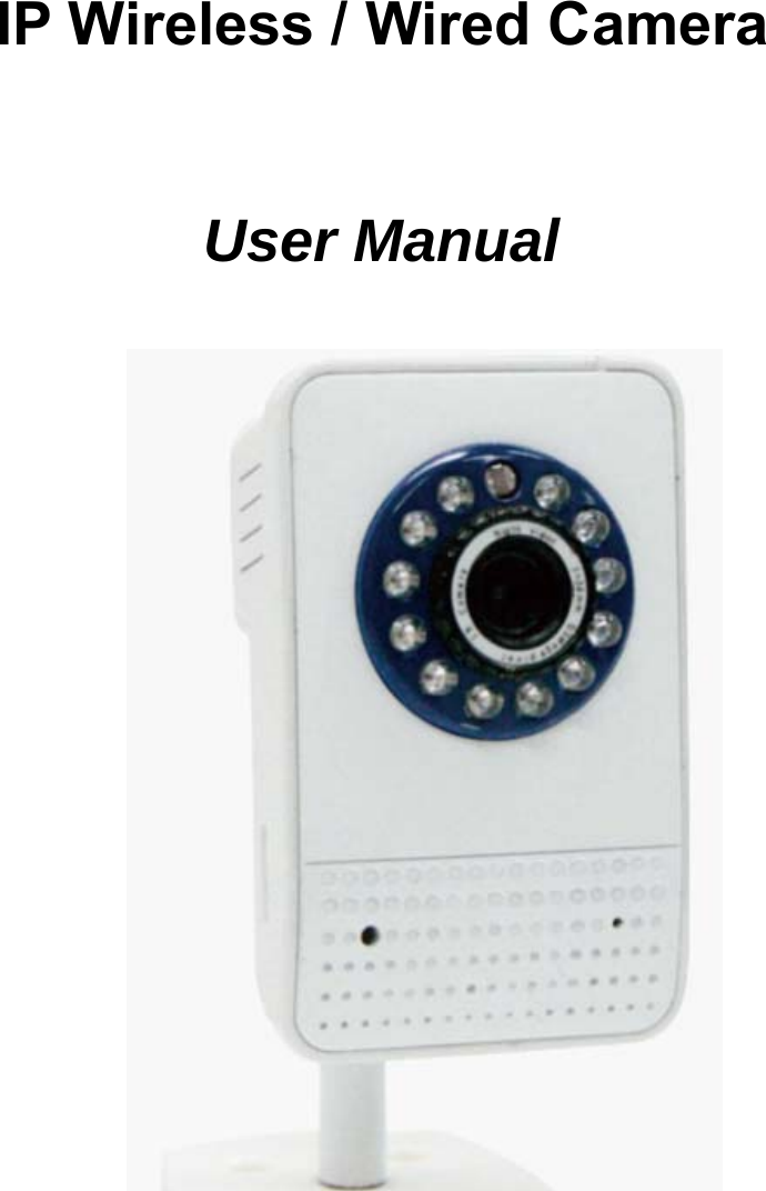
APEXIS ELECTRONIC APM-J4035-WS IP Camera User Manual
SHENZHEN APEXIS ELECTRONIC CO., LTD. IP Camera Users Manual
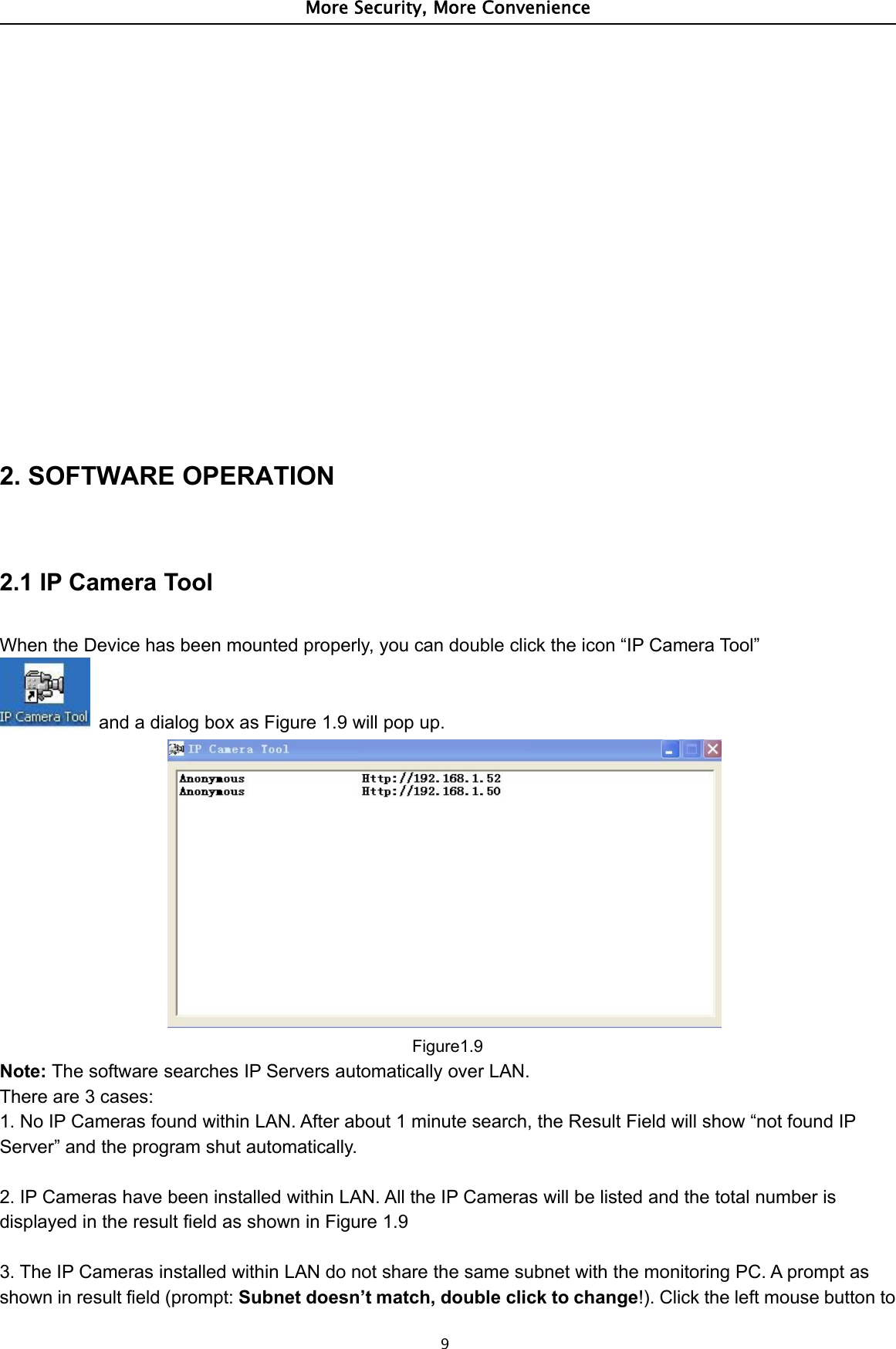
UserManual.wiki
>
APEXIS ELECTRONIC
>
APM J4035 WS User Manual
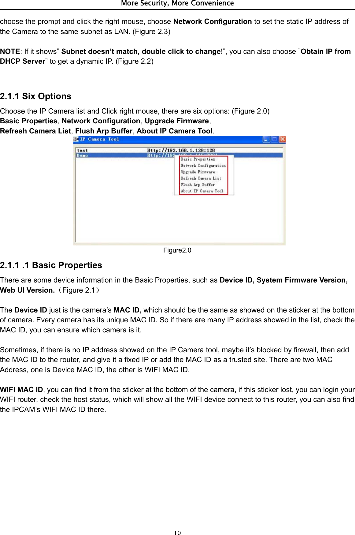
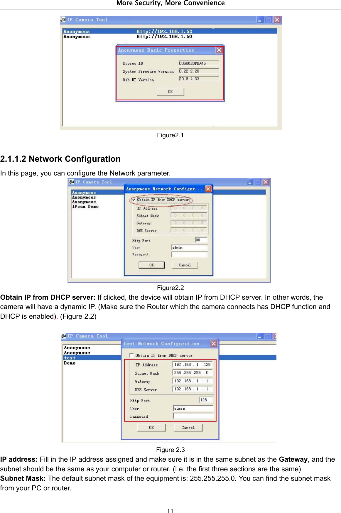
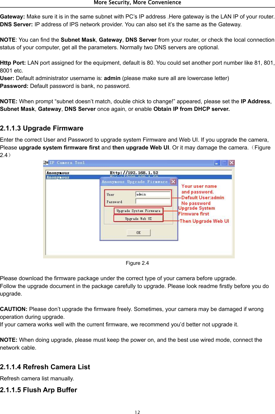
Manual
Navigation menu
Upload a User Manual
Namespaces
Wiki Guide
HTML
PDF
Info
Views
User Manual
Discussion / Help
Navigation