API Healthcare PROXIC01 RFID Module User Manual Revised 042809
API Healthcare Corp. RFID Module Users Manual Revised 042809
Users Manual Revised 042809

Last Revision: 5/11/2009 Copyright 2009 API Healthcare Corporation.
API Internal Document – Company Confidential Information
Page 1of 5
RFID Module Installation Manual
Series 500 Reader Installation
Version 1.03

Last Revision: 5/11/2009 Copyright 2009 API Healthcare Corporation.
API Internal Document – Company Confidential Information
Page 2of 5
Purpose
This document describes the installation process of the RFID Module (iCLASS) in the Series 500 Reader. This
module is an option that may be purchased by the customer.
NOTICE: Installation of this module may only be made by qualified API employees. This
is not a field upgrade, and must be done at the API factory.
FCC Notice
FCC ID: W7N-PROXIC01
Compliance Statement (Part 15.19)
This device complies with Part 15 of the FCC Rules.
Operation is subject to the following two conditions:
1. This device may not cause harmful interference, and
2. This device must accept any interference received,
including interference that may cause undesired operation.
Warning (Part 15.21)
Changes or modifications not expressly approved by the party
responsible for compliance could void the user’s authority to
operate the equipment.
FCC Interference Statement (Part 15.105 (b))
This equipment has been tested and found to comply with the limits for a Class B digital
device, pursuant to Part 15 of the FCC Rules. These limits are designed to provide
reasonable protection against harmful interference in a residential installation. This
equipment generates uses and can radiate radio frequency energy and, if not installed and
used in accordance with the instructions, may cause harmful interference to radio
communications. However, there is no guarantee that interference will not occur in a
particular installation. If this equipment does cause harmful interference to radio or
television reception, which can be determined by turning the equipment off and on, the
user is encouraged to try to correct the interference by one of the following measures:
- Reorient or relocate the receiving antenna.
- Increase the separation between the equipment and receiver.
- Connect the equipment into an outlet on a circuit different from that
to which the receiver is connected.
- Consult the dealer or an experienced radio/TV technician for help.
Installing the RFID Module
1. Remove the center pin of a 3 pin single row header with .1” pin spacing.
Last Revision: 5/11/2009 Copyright 2009 API Healthcare Corporation.
API Internal Document – Company Confidential Information
Page 3of 5
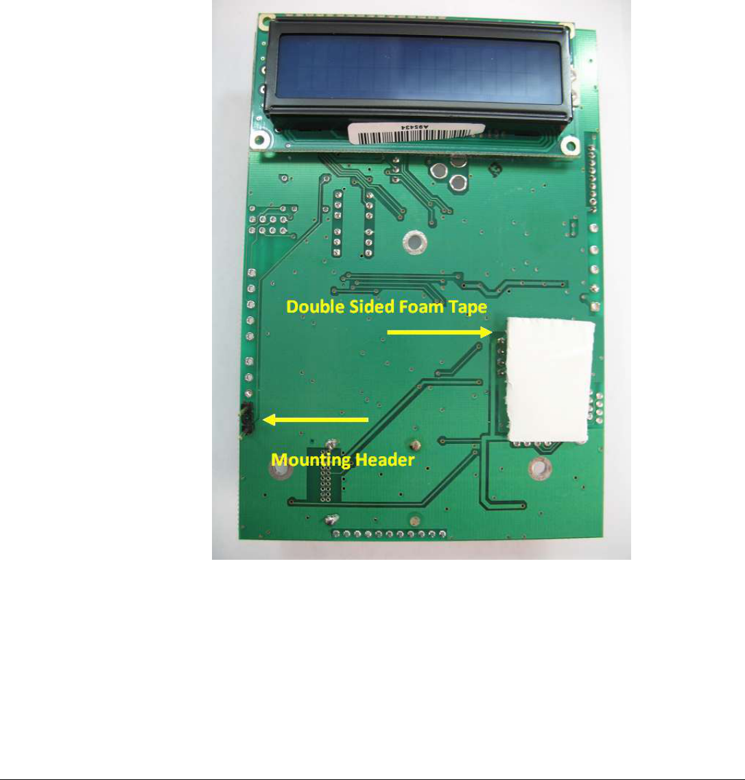
2. Solder the header into the pins shown in Figure 1 on the solder side of the Series 500 main PCB. It will
be necessary to slightly adjust the spacing of the pins. Note this header is used only for mechanical
fastening. There is no electrical connection.
3. Cut the free ends of the header to .1” length.
4. Place double sided foam at the location indicated in Figure 1.
Figure 1.
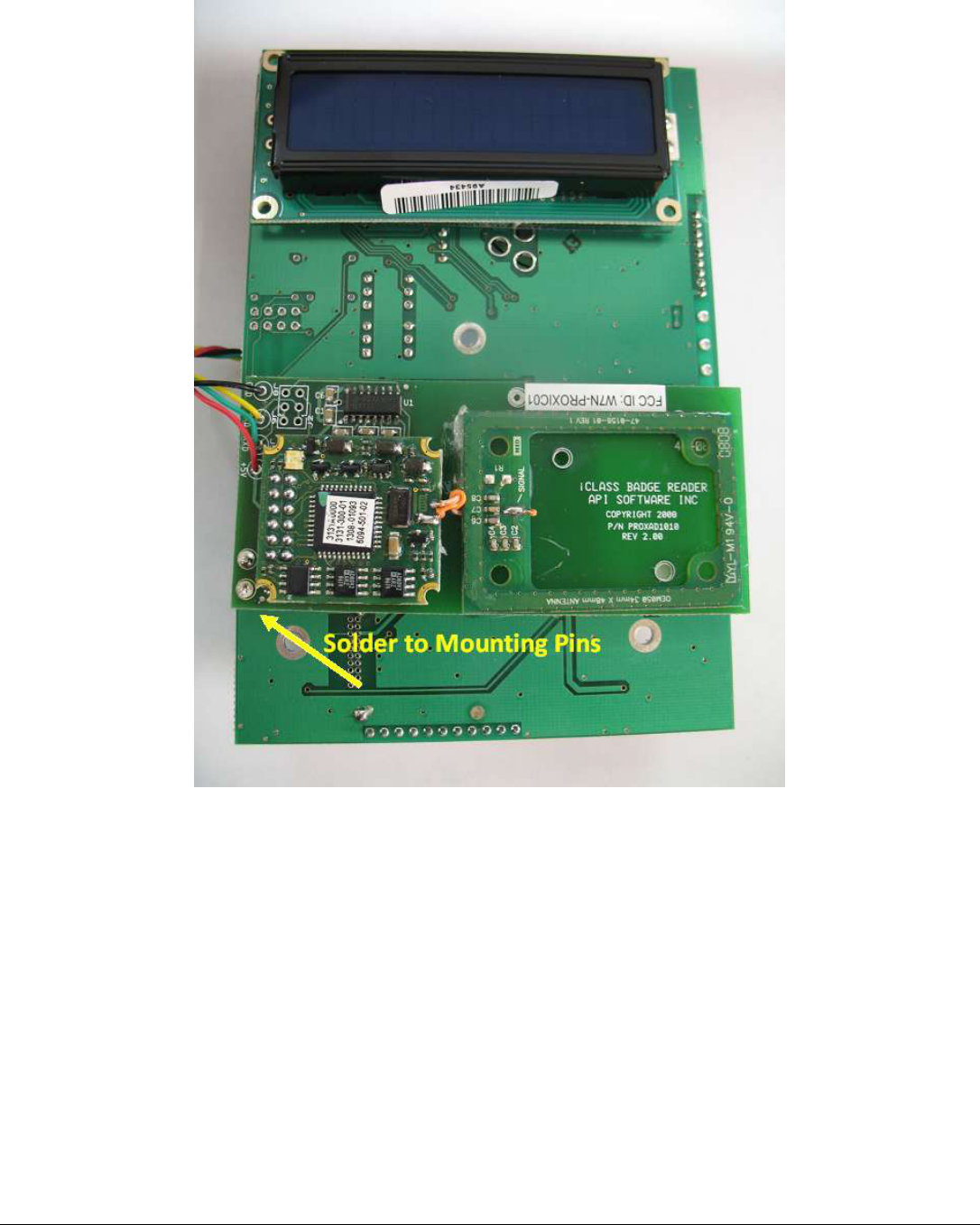
5. Place the module so the header pins line up with the mounting holes on the module.
6. Push the module down so that the foam tape secures the module.
7. Solder the two header pins to the solder pads on the module as shown in Figure 2.
Last Revision: 5/11/2009 Copyright 2009 API Healthcare Corporation.
API Internal Document – Company Confidential Information
Page 4of 5
Figure 2.
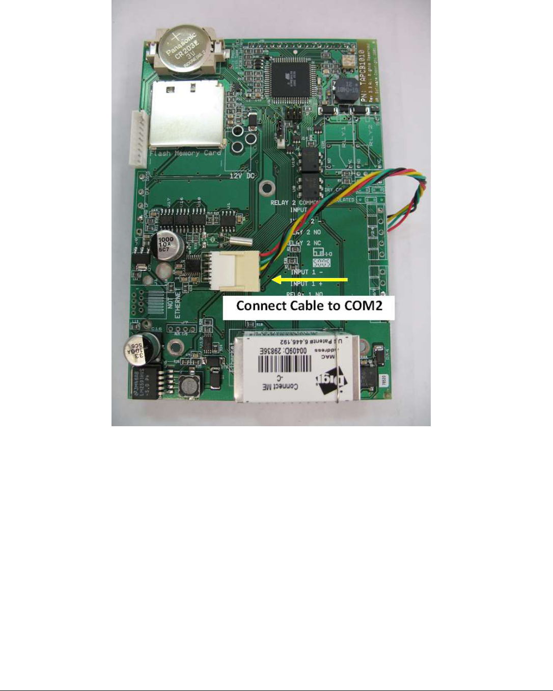
8. Connect the cable from the iCLASS RFID module to the COM2 connector as shown in Figure 3.
9. Mount the Series 500 Main PCB in the case in the normal manner.
10. Complete final assembly of the unit.
Last Revision: 5/11/2009 Copyright 2009 API Healthcare Corporation.
API Internal Document – Company Confidential Information
Page 5of 5
Figure 3.
Testing the RFID Module
1. Apply power and wait for the unit to boot up.
2. Enter Diagnostic Mode:
a. Hold the F1 key until the display shows: DIAGNOSTIC PIN
b. Enter the PIN number by pressing the following keys: 415049<ENT>
c. Press 1 (BADGE)
d. Press 1 (RAW DATA)
3. Hold the test badge near the front plate of the reader until it displays: PROX SUCCESS.
4. Verify the number displayed matches the number printed on the test card.
5. This completes test of the module.