API Healthcare PROXIN01 RF ID Module User Manual Indala RFID Inst rev 100
API Healthcare Corp. RF ID Module Indala RFID Inst rev 100
Users Manaul

Last Revision: 6/9/2009 Copyright 2009 API Healthcare Corporation.
API Internal Document – Company Confidential Information
Page 1of 5
Indala RFID Module Installation Manual
Series 500 Reader Installation
Version 1.00

Last Revision: 6/9/2009 Copyright 2009 API Healthcare Corporation.
API Internal Document – Company Confidential Information
Page 2of 5
Purpose
This document describes the installation process of the Indala RFID Module in the Series 500 Reader. This
module is an option that may be purchased by the customer.
NOTICE: Installation of this module may only be made by qualified API employees. This
is not a field upgrade, and must be done at the API factory.
FCC Notice
FCC ID: W7N-PROXIN01
Compliance Statement (Part 15.19)
This device complies with Part 15 of the FCC Rules.
Operation is subject to the following two conditions:
1. This device may not cause harmful interference, and
2. This device must accept any interference received,
including interference that may cause undesired operation.
Warning (Part 15.21)
Changes or modifications not expressly approved by the party responsible for compliance
could void the user’s authority to operate the equipment.
FCC Interference Statement (Part 15.105 (b))
This equipment has been tested and found to comply with the limits for a Class B digital
device, pursuant to Part 15 of the FCC Rules. These limits are designed to provide
reasonable protection against harmful interference in a residential installation. This
equipment generates uses and can radiate radio frequency energy and, if not installed and
used in accordance with the instructions, may cause harmful interference to radio
communications. However, there is no guarantee that interference will not occur in a
particular installation. If this equipment does cause harmful interference to radio or
television reception, which can be determined by turning the equipment off and on, the
user is encouraged to try to correct the interference by one of the following measures:
- Reorient or relocate the receiving antenna.
- Increase the separation between the equipment and receiver.
- Connect the equipment into an outlet on a circuit different from that to
which the receiver is connected.
- Consult the dealer or an experienced radio/TV technician for help.
Installing the Indala RFID Module
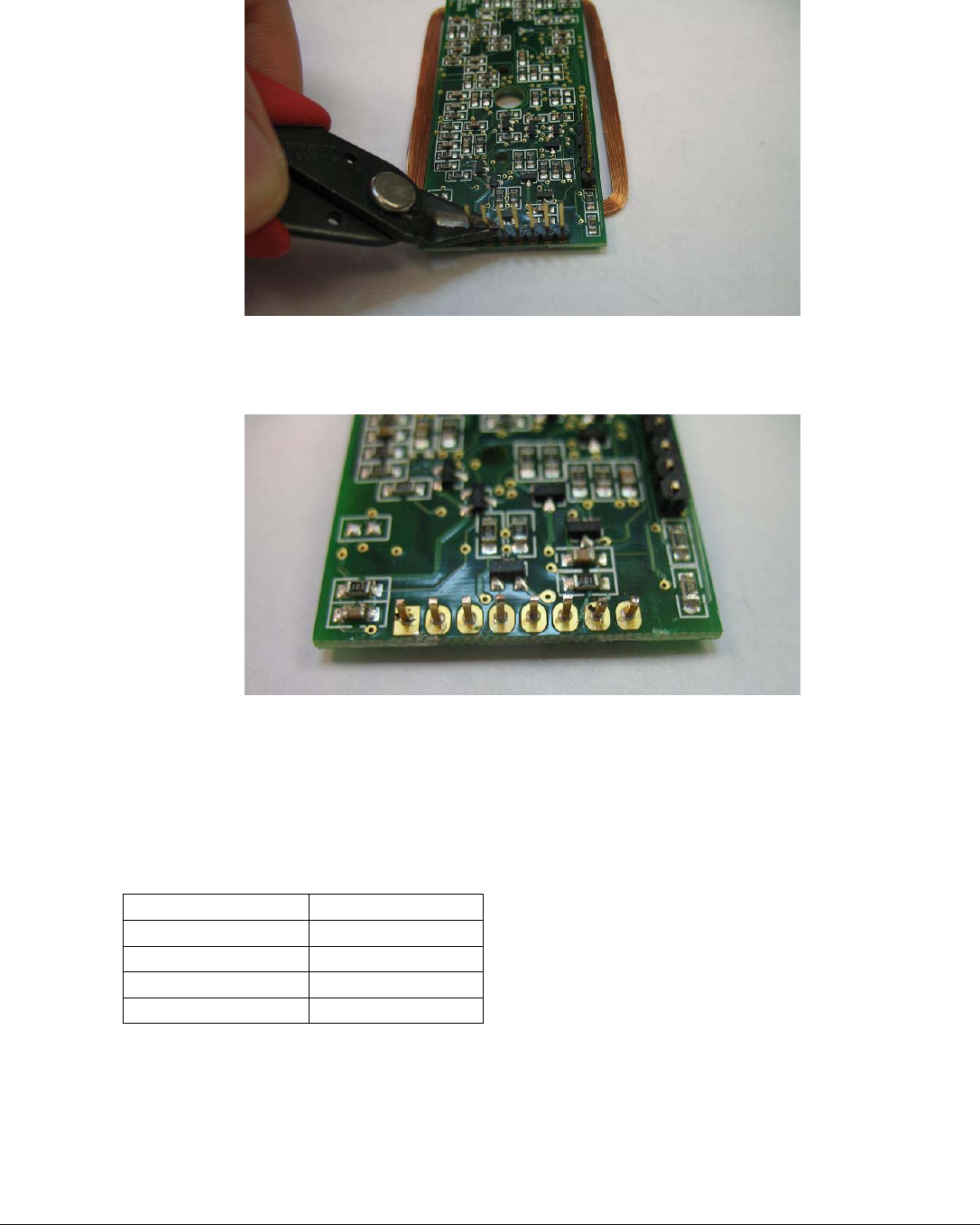
1. Cut the long pins flush on the two headers on the Indala board per Figure 1.
Last Revision: 6/9/2009 Copyright 2009 API Healthcare Corporation.
API Internal Document – Company Confidential Information
Page 3of 5
Figure 1.
2. Carefully pull the plastic spacer off the header at the end of the board, leaving the pins intact per Figure
2.
Figure 2.
3. Cut pins all the pins except 1, 3, 4, & 5 flush with the circuit board.
4. Tin the remaining pins with solder.
5. Solder the wires to the Indala header pins. Gently tug on each wire to ensure a strong mechanical joint.
Ensure there are no shorts between wires.
Indala Pin Wire Color
1 Red
5 Black
3 Yellow
4 Green
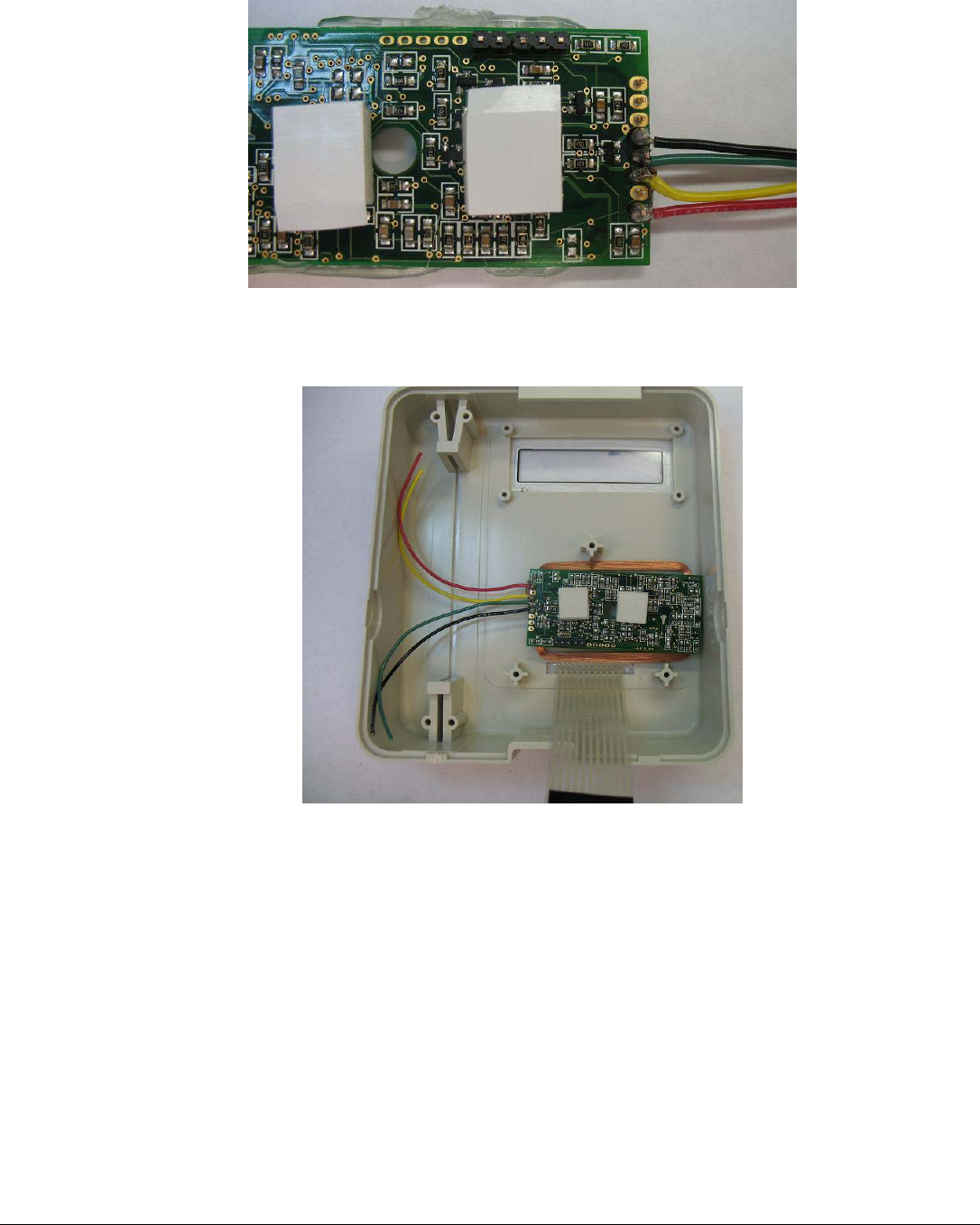
6. Insert two stand offs into the Indala board per Figure 3.
Last Revision: 6/9/2009 Copyright 2009 API Healthcare Corporation.
API Internal Document – Company Confidential Information
Page 4of 5
Figure 3.
7. Place the assembly in the case as shown in Figure 4.
Figure 4.
8. Remove the paper covering the adhesive on the stand offs. Place the TA-500 board in the case. Align
the TA-500 board so the mounting holes line up with the 3 case mounting bosses. Press gently to make
contact with the Indala board stand offs.
9. Remove the TA-500 circuit board. The Indala should be mounted on the board. Press firmly on the
Indala board to ensure good adhesion between the two boards.
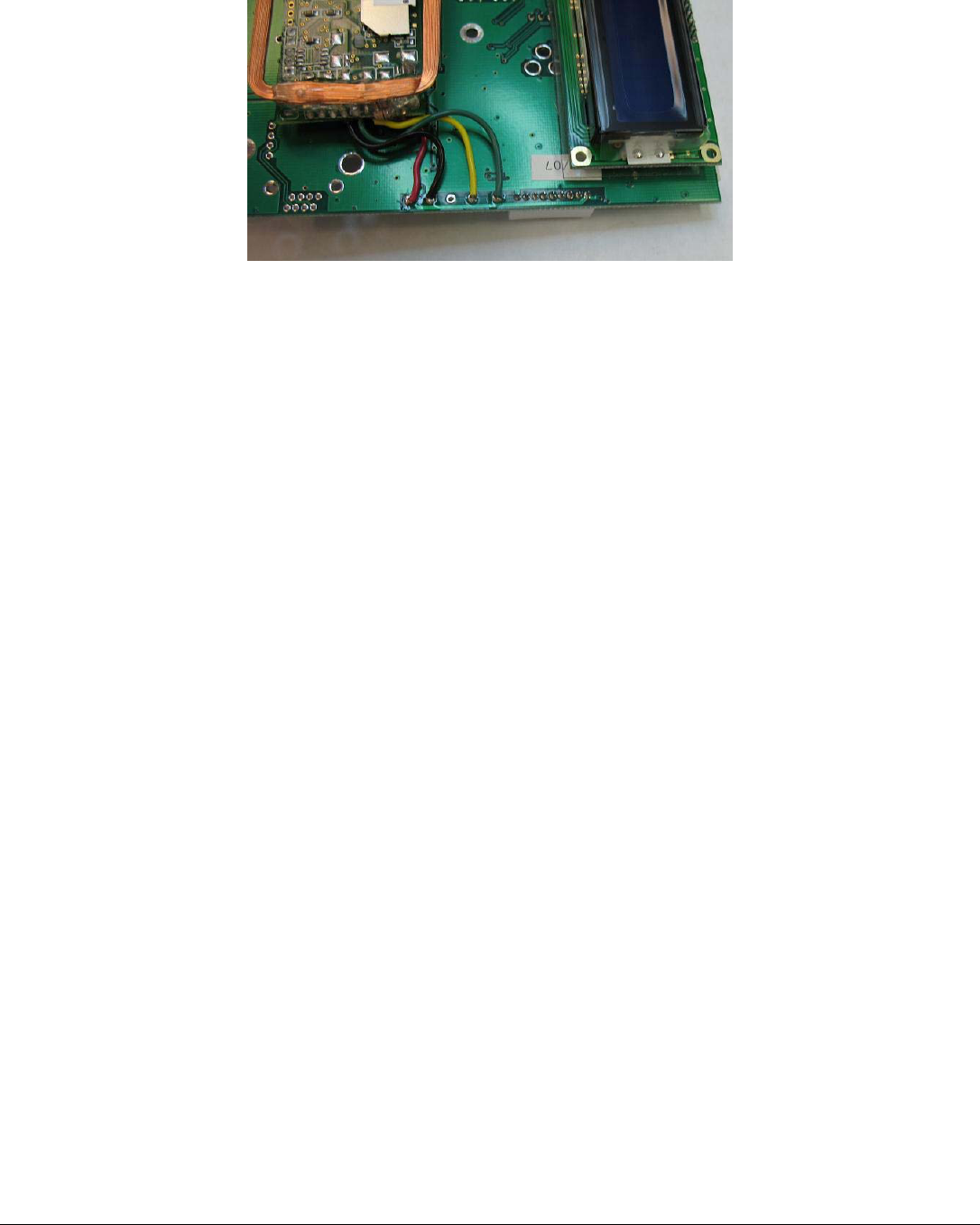
10. Per Figure 5, trim the wires to the proper length and strip off 1/8” from the free ends. Solder the wires
from Indala cable harness as follows:
a. Red wire to J8-1 (+5V)
b. Black wire to J8-2 (GND)
c. Yellow wire to J8-4 (CLK)
d. Green wire to J8-5 (DATA)
Last Revision: 6/9/2009 Copyright 2009 API Healthcare Corporation.
API Internal Document – Company Confidential Information
Page 5of 5
Figure 5.
11. Mount the Series 500 Main PCB in the case in the normal manner.
12. Complete final assembly of the unit.
Testing the Indala RFID Module
1. Apply power and wait for the unit to boot up.
2. Enter Diagnostic Mode:
a. Hold the F1 key until the display shows: DIAGNOSTIC PIN
b. Enter the PIN number by pressing the following keys: 415049<ENT>
c. Press 1 (BADGE)
d. Press 1 (RAW DATA)
3. Hold the test badge near the front plate of the reader until it displays: PROX SUCCESS.
4. Verify the number displayed matches the number printed on the test card.
5. This completes test of the module.