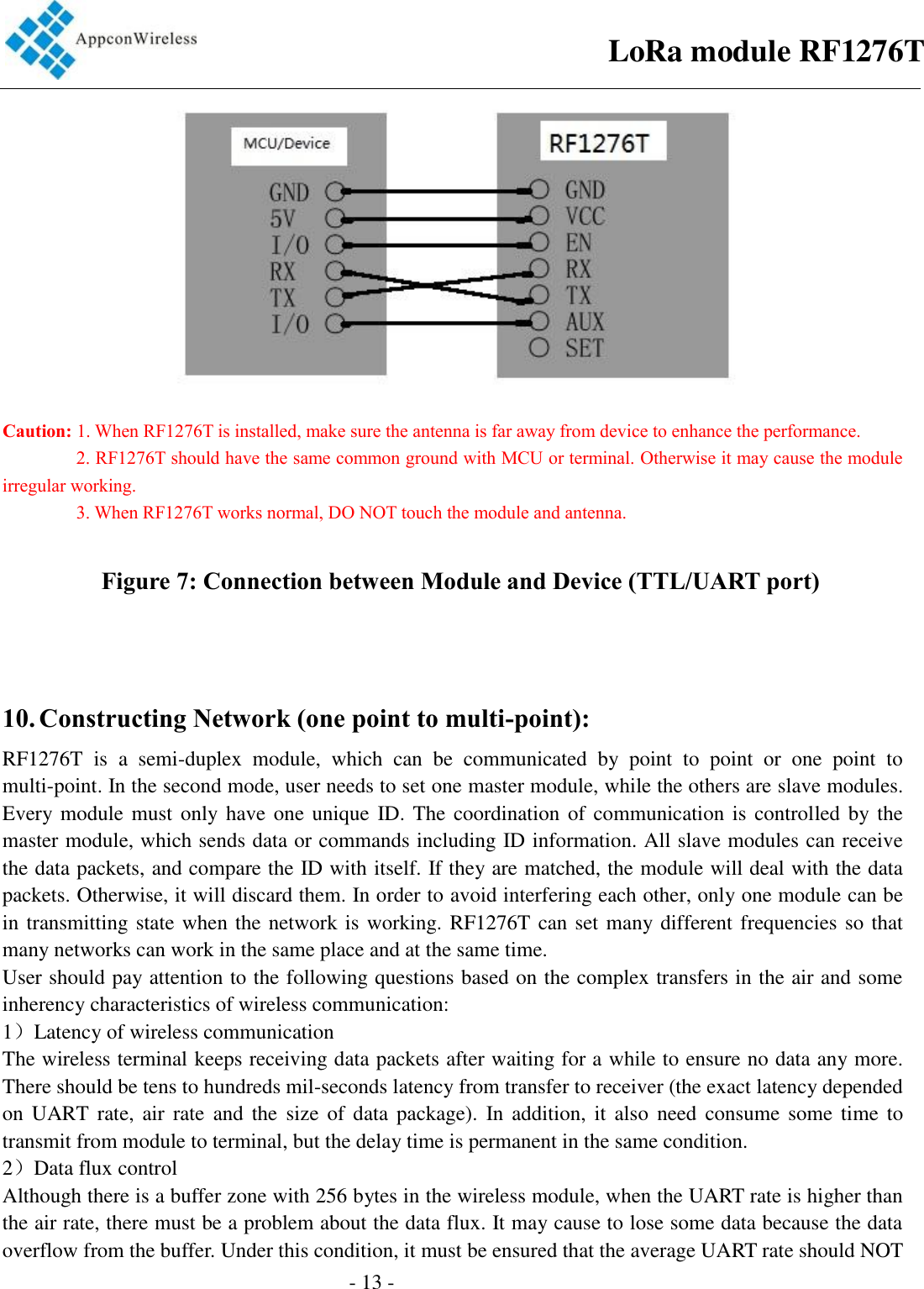
APPCON WIRELESS TECHNOLOGY RF1276T LoRa module User Manual RF1276T

APPCON WIRELESS TECHNOLOGY LIMITED LoRa module RF1276T

User manual

                                                - 1 -                                          1. GeneralRF1276T series is a low cost, ultra-low power, high performance transparent two way semi-duplex LoRa modulation transceiver with operation at 915Mhz ISM band. It integrates with high speed MCU from ST and high  performance  RF  IC  SX1276.  Adopting  high  efficiency  forward  error  correction  with  interleaving encoding  (FEC)  technology,  it  makes  anti-interference  ability  and  reception  sensitivity  greatly  improved. That guarantees good performance in  the harsh environment such  as  some industrial  application. The FEC technology is advanced and unique in radio data communication field.   RF1276T  has  the  UART  interface,  that  make  it  is  easy  to  implement  wireless  data  transmission.  It  is flexible for users to set the baud rate, frequency, output power, air data rate etc parameters. It can transmit transparent data with large data buffer and also can provide over 26 channels. The compact size makes it an ideal option for radio data communication application.   LoRa module RF1276T
                                                - 2 -                                       2. Features     Air data rate: 300 - 19200bps, can be configured through RF tool    UART data rate: 1200 - 57600bps, can be configured through RF tool    Frequency: 902.5MHz – 927.5MHz    Working Current: 90mA(TX), 19.2mA(RX), 22uA(wake-up), 3.9uA(Sleeping)  26 channels  parity of series COM: 8E1/8N1/8O1  LoRa modulation  Receive sensitivity: -148dBm(@600bps)  UART/TTL  Exceed 256 bytes data buffer  Supply Voltage: 3.3V – 5.5V  Simply tool for configuration  Dimension: 34.2mm x 18.4mm x 7.0mm  3. Application:   Automated Meter Reading (AMR)  Remote control, remote measurement system  Access control  Data collection  Identification system  IT household appliance  Wireless alarm system LoRa module RF1276T
                                                 - 3 -                                        4. Maximum specification  Symbol  Parameter  Min  Max  Units VCC  Supply Voltage  3.3  5.5  V TOT  Operation Temperature  -30 85 ℃ HOH  Operation Humidity  10% 90%   TST  Storage Temperature  -55  125  °C   5. Pin Out: RF1276T module has 7 pins. Refers to the Table 1:  RF1276T Pin NO.  Pin Name  Function  Description 1  GND  Ground  Grounding of Power Supply 2  VCC    Power  Power supply DC 3.3V-5.5V 3  EN  Input  Enable pin, Low effective 4  RXD  Input  RXD: UART input, TTL level 5  TXD  Output  TXD: UART output, TTL level 6  AUX  Output  Data indication pin for waking up module 7  SET  Input  Control pin, effective in central/node mode  Table 1: Pin definition     LoRa module RF1276T
                                                 - 4 -                                       6. Working mode      a. Standard mode   Standard mode is also called transparent mode in which the module receives from or sends data to the host through serial port (RS232 or RS485) at preset data format and users don’t need to care about the proce ss of data inside the module. The AUX pin of RF1276T will give indication about the data IN/OUT of serial port 2ms in advance in order to wake up the host.  Timing Sequence in Standard Mode  b. Star network mode   In this mode one RF1276T module needs to set as the central module and other modules should be node modules. For central module, it works at the full performance so its power consumption is the same as in the standard mode. As to node module, some functions of it are closed. If the EN pin is connected to logic high, the node module only keeps CAD wireless monitor to detect if there is any wireless signal coming and will not check if there is any data from the host through UART interface. If the node module sends data to  the  central  module,  the host  needs to set  EN  pin  to  low  to  activate  the  node  module  and  then transfers the data.     In the configuration tool, there is an option for Node ID which is used to set the ID of node module. If the ID of the node modules is 0x00 0x00, the node module will not make address detection. In other words all of the nodes will receive the data including address from central module. The data package of the first two bytes should be the node ID.      LoRa module RF1276T
                                                 - 5 -                                       E.g. The Central module sends data‘0x00 0x01 0x22 0x33 0x44 0x55’, all of the node modules with ID ‘0x00 0x00’ will receive the data ‘0x00 0x01 0x22 0x33 0x44 0x55’. If the ID of node module is larger than 0x00 0x00, the node module with ID the same as the one in the first two bytes of data package can receive the real data.  E.g. The Central module sends data ‘0x00 0x01 0x22 0x33 0x44 0x55’, the module with ID ‘0x00 0x01’ can get the data ‘0x22 0x33 0x44 0x55’and the first two byte ID will be filtered.   In order to guarantee the reliability of communication, the length of data package should not exceed 64 bytes.  c. Relay module RF1276T can  act  reply module when  the  peer  to  peer communication range is  not  enough. The Relay module has the same hardware with RF1276T module, but Relay module has the different firmware. The Relay module has two network IDs. One network ID is the same as the Central module. Another one is the same as the Node module. Relay module  acts as  transfering the data from the Central or Node.  In the below chart, it is shown the Relay in the network.     The relay module can be configured via RF tool   LoRa module RF1276T
                                                 - 6 -                                        The  Net  ID  is  the  same  as  Central’s  Net  ID.  The  Node  ID  is  the  same  as  Net  ID  of  Node.  The  other parameters also should be the same as the network configuration.    d, Express communication mode.   The logic level of SET pin is used to switch between express communication and breath period communication in central/node mode. In sleep mode, the SET pin should be connected to logic high or suspended. If the SET pin is set to high, the node module will keeps CAD wireless monitor to detect if there is any wireless signal coming at the interval of the breath period. If the SET pin is set to logic low, the node module will keep in receive mode so the central module will not need to send long preamble. The most importance is the logic level of SET for central module must be the same as the node module.           LoRa module RF1276T
                                                 - 7 -                                       2018-4-20 7. Dimension  Figure 1: Size of Module 8. Parameter Configuration Through  serial  port  or  using  setting  tool  ‘Rf-Tool’,  users  can  configure  relative  parameters  such  as frequency, UART rate, air rate, checkout mode and so on.    It is very simply for configuration. Based on different requirement, all options can be selected visually. It is shown in Table 2 and Figure 3. Parameter  Description UART area  The values are fixed at 9.6k bps & no parity check. RF frequency  It indicates the center frequency of RF carrier RF mode  Standard mode, Low Power mode RF_Factor  Lora spreading factor. Larger value means higher sensitivity but longer air transmission time 无线速率 收发频率 无线功率 串口速率 设置串口 LoRa module RF1276T
                                                 - 8 -                                       RF_BW  Lora bandwidth. Larger value means lower sensitivity. Recommended value: 125K. Node ID  It is available in the Central/Node mode.   Net ID  Only the modules with the same network ID can communicate with each other. It can avoid interferences from irrelative modules Power It is used to set the output power of RF1276T. There are 7 power levels. The 7 means the max. output power -9dBm and 0 means the lowest output power. Serial baudrate  It defines the data rate between RF1276T and the host Serial parity  It defines the parity check between RF1276T and the host Breath  It is available in the Central/Node mode.It defines the Breath period of Node module.   Wake Timer  It is available for the Node module only. It defines the time of module waking up to receive the preamble from Central module.   Table 2: Parameter Specification      Figure 3: Interface of RF Tool LoRa module RF1276T
                                                 - 9 -                                         Users can configure the  parameters (frequency, data rate, output  power, RF Factor, RF  Bandwith etc.) through PC or in circuit.    ♦ Setting through PC.  RF1276T port is UART/TTL. When RF1276T connecting with PC, users need to use USB adapter. AppconWireless provides USB adapter as accessory. The schematic is shown in Figure 4    Firstly users connect converter board to PC through DB9 cable and open ‘RF Tool’, then insert module into converter board. After that, the status column of ‘RF tool’ will give a indication ‘Found Device’. Users then can read/write the module. If users connect USB converter, USB drive ’’PL-2303_Driver_Installer’’need be installed firstly. The drive has different version for different OS. USB converter has five wires with five different colors: Black, Red, Blue, Yellow, Green. Black wire is GND pin. Red wire is VCC pin. Blue wire is TXD pin. EN pin and SET pin should be connect to GROUND.    Figure 4: The connection diagram  ♦  Setting  in  circuit  .  Users  also  can  use  microcontroller  to  change  the  default  parameters.  The  work mechanism is the same as in PC.   LoRa module RF1276T
                                                 - 10 -                                        Sync word  ID code  Header  Command  Length  Data  CRC  End code 0xAF  0xAF  0x00  0x00  0XAF  XX YY  LEN  XXXX CS  0X0D  0X0A RF1276T Command Structure Notes: 1. The ID code is 0x00 0x00 in command.   2.  In command  code, XX  in  sending command  is  0x80  and in  response command is  0x00. YY is the command type. The work mode of   YY  TYPE  YY  TYPE  YY  TYPE  YY  TYPE  YY  TYPE 0x01  write  0x02  read  0x03  standard  0x04  Central  0x05  Node Command Type and Value 3.  Length refers  to  the  data  bytes between  Length  byte  and  CRC  byte  which  the  two  bytes  are  not calculated in the length.     4. Data refers to the detailed parameters which need to be changed. Baudrate  Parity  Frequency  RF_Factor  Mode  RF_BW  ID  NetID  Power Parameter Sequence in Data Section            LoRa module RF1276T
- 11 - Parameter  Unit  Length(Byte)  Decription Serial Baudrate  Kbps  1  1.2, 2.4, 4.8, 9.6, 19.2, 38.4, 57.6 equals to 1,2,3,4,5,6,7 Parity  1  0: No parity; 1: Odd parity; 2: Even parity Freq.  MHz  /   RF_Factor  Chips  1  7=128, 8=256, 9=512, 10=1024, 11=2048, 12=4096 RF_BW  Kbs  1  6=62.5K,7=125K,8=256K,9=512K Output power  dBm  1  1~7; 1 refers to -9dBm and  7 for 0dBm  Breath  s  1  0=2s,1=4s,2=6s,3=8s, 4=10s Wake Timer  ms  1  0=2ms, 1=4ms, 2=8ms 3= 16ms 4= 32ms, 5= 64ms;   Parameter Length & Value Range 5. CS refers to CRC code which is the remainder of the sum of data section divided by 256 In order tounderstand the command. The section will demonstrate the use of commands by some examples. Write Command Code: 0x01 Command: 0xAF, 0xAF, 0x00, 0x00, 0xAF, 0x80, 0x01, 0x0C, .... CS, 0x0D, 0x0A Response.: 0xAF, 0xAF, 0x00, 0x00, 0xA F, 0x00, 0x01, 0x0C, .... CS, 0x0D, 0x0A Read Command Code: 0x02   Command: 0xAF, 0xAF, 0x00, 0x00, 0xAF, 0x80, 0x02, 0x02,0x00,0x00,0x91, 0x0D, 0x0A Response.: 0xAF, 0xAF, 0x00, 0x00, 0xAF, 0x00, 0x02, 0x02,0x00,0x00,0x91, 0x0D, 0x0A Standard Mode Command Code: 0x03   Command: 0xAF, 0xAF, 0x00, 0x00, 0xAF, 0x80, 0x03, 0x02, 0x00, 0x00, 0x92, 0x0D, 0x0A LoRa module RF1276TChannel Spacing: 1MHzChannel Number: 26Operating Frequency: 902.5MHz~927.5MHz
                                                 - 12 -                                       Response.: 0xAF, 0xAF, 0x00, 0x00, 0xAF,    0x00, 0x03, 0x02, 0x00, 0x00, 0x92, 0x0D, 0x0A      Central Mode Command Code: 0x04   Command: 0xAF, 0xAF, 0x00, 0x00, 0xAF, 0x80, 0x04, 0x02, 0x00, 0x00, 0x93, 0x0D, 0x0A   Response.: 0xAF, 0xAF, 0x00, 0x00, 0xAF,    0x00, 0x04, 0x02, 0x00, 0x00, 0x93, 0x0D, 0x0A      Node Mode Command Code: 0x05   Command: 0xAF, 0xAF, 0x00, 0x00, 0xAF, 0x80, 0x05, 0x02, 0x00, 0x00, 0x94, 0x0D, 0x0A   Response.: 0xAF, 0xAF, 0x00, 0x00, 0xAF, 0x00, 0x05, 0x02, 0x00, 0x00, 0x94, 0x0D, 0x0A      Please note that the working modes changed by the 0x03, 0x04 and 0x05 commands will not be written into nonvolatile memory so the working mode will be restored to the former mode before change after power-off. Users can use the WRITE command to change the working mode of module to standard mode or low power mode but the sleep mode will be restored to standard mode after next power-on even if the WRITE command is used.   9. Application Schematic:  The connection schematic between RF1276T and MCU or terminal is shown as below.   The parameter of RF1276T’serial port must match with MCU or terminal’s (RF1276T has the same serial port baud rate and parity style with MCU or terminal). Two or more RF1276Ts in a system should have the same parameters such as TX/RX frequency, air date rate and RF channel.   LoRa module RF1276T
                                                 - 13 -                                        Caution: 1. When RF1276T is installed, make sure the antenna is far away from device to enhance the performance.                 2. RF1276T should have the same common ground with MCU or terminal. Otherwise it may cause the module irregular working.                 3. When RF1276T works normal, DO NOT touch the module and antenna.          Figure 7: Connection between Module and Device (TTL/UART port)    10. Constructing Network (one point to multi-point): RF1276T  is  a  semi-duplex  module,  which  can  be  communicated  by  point  to  point  or  one  point  to multi-point. In the second mode, user needs to set one master module, while the others are slave modules. Every module must  only have one unique  ID. The  coordination of  communication is  controlled by the master module, which sends data or commands including ID information. All slave modules can receive the data packets, and compare the ID with itself. If they are matched, the module will deal with the data packets. Otherwise, it will discard them. In order to avoid interfering each other, only one module can be in transmitting state when the network is working. RF1276T can set many different frequencies so that many networks can work in the same place and at the same time. User should pay attention to the following questions based on the complex transfers in the air and some inherency characteristics of wireless communication: 1)Latency of wireless communication   The wireless terminal keeps receiving data packets after waiting for a while to ensure no data any more. There should be tens to hundreds mil-seconds latency from transfer to receiver (the exact latency depended on UART  rate,  air  rate  and  the  size of data  package).  In addition,  it  also  need  consume  some  time  to transmit from module to terminal, but the delay time is permanent in the same condition.   2)Data flux control Although there is a buffer zone with 256 bytes in the wireless module, when the UART rate is higher than the air rate, there must be a problem about the data flux. It may cause to lose some data because the data overflow from the buffer. Under this condition, it must be ensured that the average UART rate should NOT LoRa module RF1276T
                                                 - 14 -                                       higher than 60 percent of the air rate. For instance, the UART rate is 9600bps, the air rate is 4800bps. If UART rate is the same as the air rate, the only way is to interval the transmitting time. If terminal transmits 100bytes to UART every time, it will take 104ms every time. (104ms/0.6)*(9600/4800) =347ms. So if the interval time  that  terminal transmit 100bytes to  UART should  NOT less than  347ms  every time, those mentioned problems can be avoided.  3)Error control The  wireless  network  module  has  strong  capability  of  anti-interference  because  of  the  high  efficiency checking  error  correction  with  interleaving  encoding  technology.  However,  when  it  is  in  a  bad circumstance that has strong electric interference, the data may be lost or receive some error data. User can increase the development of the system link layer protocol. For instance, if user can increase TCP/IP slip window and repeat transmitting functions, it will improve the reliability and ability of wireless network communication.   4) Selection of antenna Antenna  is  a  very  important  factor  of  the  communication  system.  The  quality  of  antenna  impacts  the capability  of  communication  system.  So  user  should  strictly  choose  the  quality  of  antenna.  Generally speaking, it mainly contains two points: the type of antenna (size) and its electric capability.    The antenna must be matched with the frequency of communication system.    11. Order information  a)             RF1276T-915             LoRa module RF1276T
                                                 - 15 -                                        12. Q&A:  Questions and Answers Can not communicate between two devices 1.The  communication  protocol  is  different  between  two  modules,  for instance: data rate and checkout. 2.The frequency or RF data rate is different between two communicated modules. 3.They are not the same kind products. 4.The connection between module and terminal is wrong. 5、The module is wrong. 6.The setting of EN is wrong. 7.The communication distance exceeds the range, or the connection of antenna is bad. Short communication distance 1.The supply voltage exceeds range 2.The ripple of power is too big. 3.The connection of antenna is bad or it is a wrong kind of antenna 4.Antenna is too close to the surface of metal or the ground 5.Receiving circumstance is very bad, for instance buildings and strong interference. 6.There is interference of the same frequency Receive wrong data 1.Wrong setting of COM, for example, Baud rate is wrong 2.The connection of UART is wrong.   3.The cable to the UART is too long.    LoRa module RF1276T
FCC Statement This equipment has been tested and found to comply with the limits for a Class B digital device, pursuant to part  15  of  the  FCC  Rules.  These  limits  are  designed  to  provide  reasonable  protection  against  harmful interference  in  a  residential  installation.  This  equipment  generates,  uses  and  can  radiate  radio  frequency energy and, if not installed and used in accordance with the instructions, may cause harmful interference to radio  communications.  However,  there  is  no  guarantee  that  interference  will  not  occur  in  a  particular installation. If this equipment does cause harmful interference to radio or television reception, which can be determined by turning the equipment off and on, the user is encouraged to try to correct the interference by one or more of the following measures: • Reorient or relocate the receiving antenna. • Increase the separation between the equipment and receiver. • Connect the equipment into an outlet on a circuit different from that to which the receiver is connected. • Consult the dealer or an experienced radio/TV technician for help. Caution: Any changes or modifications to this device not explicitly approved by manufacturer could void your authority to operate this equipment. This device complies with part 15 of the FCC Rules. Operation is subject to the following two conditions: (1) This device may not  cause harmful interference, and (2) this device must accept any interference received, including interference that may cause undesired operation.  RF Exposure Information This equipment complies with FCC radiation exposure limits set forth for an uncontrolled environment.   Important Note:  Any company of the host device which install this modular with limit modular approval should perform the test of radiated emission and spurious emission according to FCC part 15C:15.249 and 15.209 requirement, only if the test result comply with FCC part 15.249 and 15.209 requirement, then the host can be sold legally.  End Product Labeling If the FCC identification number is not visible when the module is installed inside another device, then the outside of the device into which the module  is installed must also display  a  label referring to the enclosed module. This exterior label can use wording such as the following: Contains Transmitter Module FCC ID: 2APJJ-RF1276T.  Manual Information to the End User  The OEM integrator has to be aware not to provide information to the end user regarding how to install or remove this RF module in the user’s manual of the end product which integrates this module.  The end user manual shall include all required regulatory information/warning as show in this manual. The  modular  is  not  intended  to  be  fielded  serviceable  as  without  shielding,  host  manufacturer  must  be considered shielding when integrating a module. When  the  module  is  installed  inside  another  device,  the  user  manual  of  this  device  must  contain  below warning statements; This device complies with Part 15 of the FCC Rules. Operation is subject to the following two conditions: (1) This device may not cause harmful interference. (2) This device must accept any interference received, including interference that may cause Changes  or  modifications  not  expressly  approved  by  the  party  responsible  for  compliance  could  void  the user's authority to operate the equipment. The devices must be installed and used in strict accordance with the manufacturer's instructions as described in the user documentation that comes with the product.                     LoRa module RF1276T- 16 -
ISED Statement - English: This device complies with Industry Canada license‐exempt RSS standard(s). Operation is subject to the following two conditions: (1) This device may not cause interference, and (2) This device must accept any interference, including interference that may cause undesired operation of the device.  - French: Le présentappareilestconforme aux CNR d'Industrie Canada applicables aux appareils radio exempts de licence. L'exploitationestautorisée aux deux conditions suivantes: (1) l'appareil ne doit pas produire de brouillage, et (2) l'utilisateur de l'appareildoit accepter tout brouillageradioélectriquesubi, mêmesi le brouillageest susceptible d'encompromettre le fonctionnement.  Radiation Exposure Statement This equipment complies with Canada radiation exposure limits set forth for an uncontrolled environment.  Cet  équipement  est  conforme  Canada  limites  d'exposition  aux  radiations  dans  un  environnement  non contrôlé.   This device is intended only for OEM integrators under the following condition: The transmitter module may not be co-located with any other transmitter or antenna. As  long  as  the  condition  above  is  met,  further  transmitter  test  will  not  be  required.  However,  the  OEM integrator  is  still  responsible  for  testing  their  end-product  for  any  additional  compliance  requirements required with this module installed. Cet appareil est conçu uniquement pour les intégrateurs OEM dans les conditions suivantes: Le module émetteur peut ne pas être coïmplanté avec un autre émetteur ou antenne. Tant  que  les  1  condition  ci-dessus  sont  remplies,  des  essais  supplémentaires  sur  l'émetteur  ne  seront  pas nécessaires. Toutefois, l'intégrateur OEM est toujours responsable des essais sur son produit final pour toutes exigences de conformité supplémentaires requis pour ce module installé.  Important Note:  Any company of the host device which install this modular with limit modular approval should perform the test of radiated emission and spurious emission according to RSS-210 and RSS-Gen requirement, only if the test result comply with RSS-210 and RSS-Gen requirement, then the host can be sold legally. Note Importante: toute  entreprise  de  l'hôte  qui  installent  ce  dispositif  modulaire  avec  limite  approbation  devrait  effectuer l'essai des modules et des rayonnements non essentiels des émissions rayonnées selon rss-210 et le cnr - gen, seulement si le résultat d'essai conforme rss-210 et le cnr - gen, puis l'hôte peut être vendu légalement.  End Product Labeling The final end product must be labeled in a visible area with the following: Contains IC: 23851-RF1276T.   Plaque signalétique du produit final Le produit final doit être étiqueté dans un endroit visible avec l'inscription suivante: Contient des IC: 23851-RF1276T.  Manual Information to the End User The OEM integrator has to be aware not to provide information to the end user regarding how to install or remove this RF module in the user’s manual of the end product which integrates this module. The end user manual shall include all required regulatory information/warning as show in this manual. Manuel d'information à l'utilisateur final L'intégrateur OEM doit être conscient de ne pas fournir des informations à l'utilisateur final quant à la façon d'installer  ou  de  supprimer  ce  module  RF  dans  le  manuel  de  l'utilisateur  du  produit  final  qui  intègre  ce module. Le manuel de l'utilisateur final doit inclure toutes les informations réglementaires requises et avertissements comme indiqué dans ce manuel.                  LoRa module RF1276T- 17 -

Navigation menu