ARGtek Communication ARGTEK-1000 802.11 b/g CPE (Access Point) User Manual AIP W608H datasheet word file 2
ARGtek Communication Inc. 802.11 b/g CPE (Access Point) AIP W608H datasheet word file 2
UserManual.wiki
>
ARGtek Communication
>
ARGTEK 1000 User Manual
Users manual
Navigation menu
Upload a User Manual
Namespaces
Wiki Guide
HTML
PDF
Info
Views
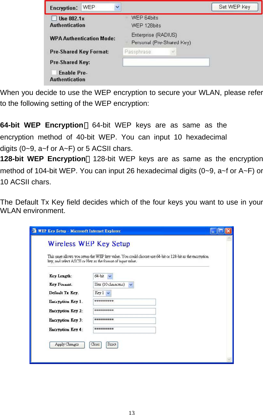
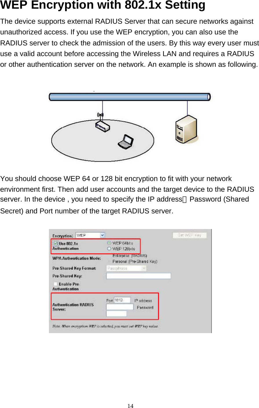
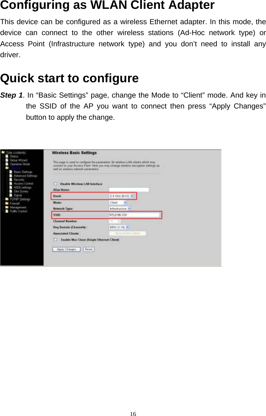
User Manual
Discussion / Help
Navigation