ARGtek Communication WIFI-018 ARGTEK GM5 WLAN 802.11b/g/n USB adapter User Manual
ARGtek Communication Inc. ARGTEK GM5 WLAN 802.11b/g/n USB adapter
UserManual.wiki
>
ARGtek Communication
>
WIFI 018 User Manual
User Manual
Navigation menu
Upload a User Manual
Namespaces
Wiki Guide
HTML
PDF
Info
Views
User Manual
Discussion / Help
Navigation
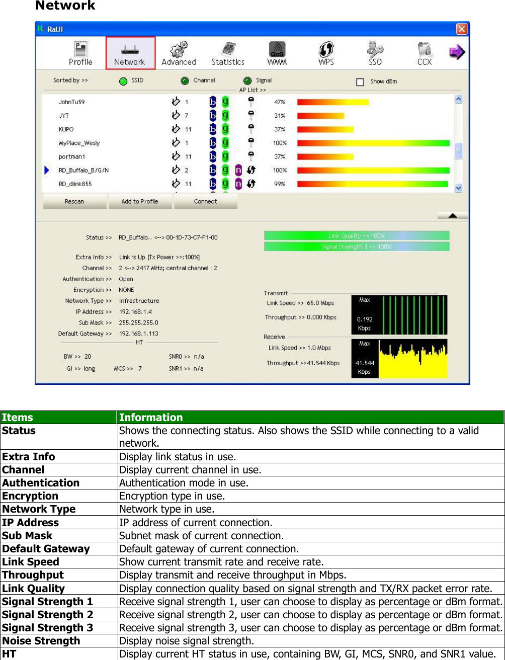
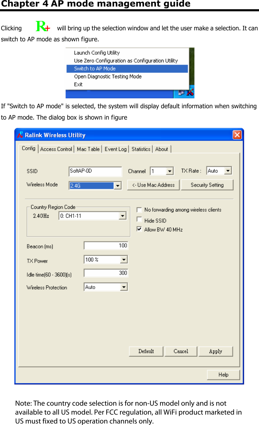
![Config Setting User can set and display detailed Soft AP information in this dialog box. Items Information SSID AP name of user type. The user also can select [Use Mac Address] to display it. System default is SoftAP-XX (XX is last two numbers of MAC address). Wireless Mode Select wireless mode. 2.4G and 5G are supported. System default is 2.4G. ( 802.11 B/G/N mix selection item only exists for B/G/N adapter ) Country Region Code The Country Region Code allows the user to specify the available channel list based on their country's regulations. Beacon (ms) The time span between two successive4 beacons. System default is 100 ms. TX Power The transmitting power of Soft AP. System default is 100%. Idle Time The allowed idle time before proceeding with the authentication. The default is 300. Wireless Protection The user can chose from Auto, on, and off. System default is auto. (802.11n wireless cards don’t support wireless protection.) a. Auto: STA will dynamically change according to the AP. b. On: Always send frames with protection. c. Off: Always send frames without protection. Channel Select the AP’s operating channel manually. System default is channel 1. TX Rate The transmitting rate. The default is auto. (802.11n wireless cards don’t support TxRate.) Note: The country code selection is for non-US model only and is not available to all US model. Per FCC regulation, all WiFi product marketed in US must fixed to US operation channels only.](https://usermanual.wiki/ARGtek-Communication/WIFI-018/User-Guide-1447099-Page-28.png)
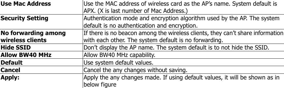
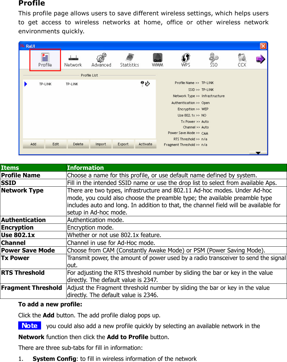
![Access Control AP connected or can’t connect with Mac address that user setting. Items Information Access Policy There are three policies available in the drop-down list. They are Disable, Allow All, and Reject All. System default is disabled. Mac Address In order to add an entry into the access control list, the user should input the MAC address without "-" in the text box and then click the "Add" button. Access List Display all Mac Addresses that the user has set. Delete Delete the Mac address set by user. Remove All Remove all Mac addresses in [Access List]. Apply Apply the above changes.](https://usermanual.wiki/ARGtek-Communication/WIFI-018/User-Guide-1447099-Page-30.png)