ARRIS Global ONT2E4021IWN EPON ONU User Manual
Pace Micro Technology plc EPON ONU
User Manual
ONT-2-E4xxxi Multi-service
Residential Gateway Series
Hardware Installation Guide
for ONT-2-E4000i, ONT-2-E4020i, ONT-2-E4021i, ONT-2-E4020iWn,
ONT-2-E4021iWn, and ONT-2-E4001i
UNRELEASED DRAFT 01/15/14
TM 87-10879 Rev A
January 2014

ONT-2-E4xxxi Multi-service Residential Gateway Series Hardware Installation Guide
ii UNRELEASED DRAFT TM 87-10879 Rev. A
Copyright © 2014 Aurora Networks. All rights reserved.
All rights reserved. No part of this document may be reproduced, stored in a retrieval system, or transmitted, in
any form or by any means, electronic, mechanical, photographic, magnetic, or otherwise, without the prior written
permission of Aurora Networks.
Aurora Networks makes no representations, express or implied, with respect to this documentation or any of the
software it may describe, including (with no limitation) any implied warranties of utility, merchantability or
fitness for any particular purpose. All such warranties are expressly disclaimed. Neither Aurora Networks nor its
distributors or dealers shall be liable for any indirect, incidental or consequential damages under any circum-
stances.
(The exclusion of implied warranties may not apply in all cases under some statutes, and thus the above exclusion
may not apply.)
Specifications are subject to change without notice. Every attempt has been made to make this manual complete,
accurate, and up-to-date. Readers are cautioned, however, that Aurora Networks reserves the right to make
changes without notice and shall not be responsible for any damages, including indirect, incidental or conse-
quential damages, caused by reliance on the material presented, including, but not limited to, omissions, typo-
graphical, arithmetical, or listing errors in the material.
Aurora Networks, the Aurora logo, LcWDM, PWRLink, SUPRALink, and Trident7 are registered trademarks of Aurora
Networks, Inc. AUROS, BitCoax, Fiber on Demand, Light-Plex, MAXLink, METROLink, Node PON, OBI-free, Opti-Trace,
PWRBlazer, Remote QAM, SMART Media Converter, Universal Digital Return Platform, and VHub are trademarks of
Aurora Networks, Inc. Other product and company names mentioned herein may be trademarks of their respective owners and
are used here only for identification purposes.
Revision
Date
ECO Number
Rev. A Initial release. xxxxx xxxxx
Visit www.aurora.com for the latest documentation release information.
Aurora Networks, Inc.
5400 Betsy Ross Drive
Santa Clara, CA 95054 USA
Phone +1 408.235.7000
Fax +1 408.845.9043
www.aurora.com
ONT-2-E4xxxi Multi-service Residential Gateway Series Hardware Installation Guide
TM 87-10879 Rev. A UNRELEASED DRAFT iii
Table of Contents
Chapter 1 Introduction ................................................................................................... 1
1.1 Welcome .................................................................................................................................................. 1
1.2 About This Manual .................................................................................................................................. 1
1.2.1 Conventions Used in This Guide ............................................................................................. 1
1.2.2 Manual Contents ...................................................................................................................... 2
1.2.3 Audience .................................................................................................................................. 2
1.2.4 Related Documents .................................................................................................................. 2
1.2.5 Obtaining Documents .............................................................................................................. 2
1.2.6 Product Support........................................................................................................................ 3
1.2.7 Comments and Feedback ......................................................................................................... 3
1.3 Standards Compliance .............................................................................................................................. 3
1.4 Regulatory Compliance ............................................................................................................................ 3
1.4.1 ONT-2-E4000i, ONT-2-E4020i, ONT-2-E4021i Models ........................................................ 3
1.4.2 ONT-2-E4020iWn and ONT-2-E4021iWn Models ................................................................. 4
Chapter 2 Overview ......................................................................................................... 7
2.1 Overview of ONT-2-E4xxxi Multi-service Residential Gateway Series ................................................. 7
2.2 EPON Multi-service Gateway Series Hardware Interface ....................................................................... 8
2.2.1 Gigabit Ethernet Ports (1000BASE-T) .................................................................................... 8
2.2.2 IEEE 802.11n Wireless Access Point with Support for Secured Access ................................. 8
2.2.3 RF Video Service (RF Overlay) ............................................................................................... 8
2.2.4 Voice over IP ........................................................................................................................... 8
2.3 Supported Residential Gateway (RG) Features ........................................................................................ 8
2.3.1 Network Address Translation (NAT)/NAPT (Network Address Port Translations) ............... 8
2.3.2 Dynamic Domain Name System (DDNS)................................................................................ 9
2.3.3 Dynamic Host Configuration Protocol (DHCP) Client and Server .......................................... 9
2.3.4 Security Firewall and Rich Packet Filtering............................................................................. 9
2.3.5 Advanced Quality of Service, .................................................................................................. 9
2.3.6 Virtual Server ........................................................................................................................... 9
2.3.7 Flexible Management Interfaces including Web GUI .............................................................. 9
2.4 Additional Features ................................................................................................................................ 10
2.5 Product Specifications ............................................................................................................................ 10
2.6 Physical Characteristics.......................................................................................................................... 11
Chapter 3 Hardware Description ................................................................................. 13
3.1 Package Contents ................................................................................................................................... 13
ONT-2-E4xxxi Multi-service Residential Gateway Series Hardware Installation Guide
iv UNRELEASED DRAFT TM 87-10879 Rev. A
3.2 Accessories .............................................................................................................................................13
3.3 ONT-2-E4xxxi Multi-service Residential Gateway Series Enclosure ....................................................14
3.4 LED Diagnostics on Front Panel ............................................................................................................14
3.5 Rear Panel and Interface Description .....................................................................................................16
3.6 Ethernet Connections .............................................................................................................................17
3.7 EPON SC/APC Fiber Optic Network Interface......................................................................................18
3.8 Voice Telephony Interfaces (Standard Telephone) ................................................................................18
3.9 RF Overlay .............................................................................................................................................19
3.10 Power......................................................................................................................................................19
Chapter 4 Installing the ONT-2-E4xxxi Multi-service Residential Gateway Series21
4.1 Cautions and Warnings ..........................................................................................................................21
4.2 Pre-Installation Check ............................................................................................................................21
4.3 Tools and Materials Needed ...................................................................................................................22
4.4 System Requirements .............................................................................................................................22
4.5 Situating the EPON Multi-service Gateway ONT..................................................................................23
4.6 Wall-Mounting the ONT Using the Fiber Tray ......................................................................................23
4.7 Wall-Mounting the ONT without the Fiber Tray ...................................................................................25
4.8 Vertical or Tower Mounting the ONT ....................................................................................................26
4.9 Connecting the EPON Optical Fiber to the ONT ...................................................................................27
4.9.1 Steps to Connect the Optical Fiber to the ONT ......................................................................28
4.10 Connecting Telephones to the EPON Multi-service Gateway ONT ......................................................29
4.11 Connecting Premises LAN Ethernet Wiring ..........................................................................................30
4.12 Connecting Power and Powering Up the ONT ......................................................................................31
4.13 Connecting to the GUI Interface of the ONT .........................................................................................31
Index 33
ONT-2-E4xxxi Multi-service Residential Gateway Series Hardware Installation Guide
TM 87-10879 Rev. A UNRELEASED DRAFT v
List of Figures
Figure 1 LED Indicators on EPON Multi-service Gateway ONT ................................................. 15
Figure 2 Rear Panel Ports on the ONT-2-E4020iWn..................................................................... 17
Figure 3 SC/APC Optical Fiber Plugged into Optical Network Interface ..................................... 18
Figure 4 Rear Backup Power Connector ........................................................................................ 19
Figure 5 Side Backup Power Connector ........................................................................................ 19
Figure 6 Schematic of the Back of the Fiber Tray ......................................................................... 24
Figure 7 Fiber Tray with Cover Installed on Wall ......................................................................... 24
Figure 8 EPON Multi-service Gateway Wall-mounted onto Fiber Tray ....................................... 25
Figure 9 Schematic of the Bottom of EPON Multi-service Gateway ............................................ 25
Figure 10 EPON Multi-service Gateway Wall-mounted ............................................................... 26
Figure 11 EPON Multi-service Residential Gateway ONT Vertically-Mounted .......................... 26
Figure 12 Snapping the ONT onto the Fiber Tray ......................................................................... 27
Figure 13 Typical Wall Plate Example .......................................................................................... 27
Figure 14 Fiber Optic Cable Minimum Bend ................................................................................ 28
Figure 15 SC/APC Optical EPON Port .......................................................................................... 28
Figure 16 SC/APC EPON Connector Compartment ..................................................................... 29
Figure 17 Rear Backup Power Connector ...................................................................................... 31
Figure 18 Device Info Summary Screen ........................................................................................ 32
ONT-2-E4xxxi Multi-service Residential Gateway Series Hardware Installation Guide
vi UNRELEASED DRAFT TM 87-10879 Rev. A
List of Tables
Table 1 EPON Multi-service Gateway ONT Supported Services and Features ............................... 7
Table 2 Product Specifications for ONT-2-E4xxxi Multi-service Residential Gateway Series ..... 10
Table 3 Physical Characteristics for ONT-2-E4xxxi Multi-service Residential Gateway Series .. 11
Table 4 Package Contents for ONT-2-E4xxxi Multi-service Residential Gateway Series ............ 13
Table 5 Orderable Accessories for ONT-2-E4xxxi Multi-service Residential Gateway Series ..... 14
Table 6 LED Indicators and Descriptions ...................................................................................... 15
Table 7 Rear Panel Ports on the ONT-2-E4020iWn ...................................................................... 17

ONT-2-E4xxxi Multi-service Residential Gateway Series Hardware Installation Guide
TM 87-10879 Rev. A UNRELEASED DRAFT 1
Chapter 1 Introduction
This guide introduces hardware components and installation procedures for the Aurora Networks
ONT-2-E4xxxi Multi-service Residential Gateway Series models and accessories. It provides infor-
mation you will need to install and set up the ONT-2-E4000i, ONT-2-E4020i, ONT-2-E4021i,
ONT-2-E4020iWn, ONT-2-E4021iWn, and ONT-2-E4001i models.
After you complete your installation, refer to the Aurora Networks ONT-2-E4xxxi Multi-service Resi-
dential Gateway Series Operator Guide for procedures for setting up your PC, logging in to the GUI
interface, and managing Residential Gateway and wireless features of the EPON Multi-service Gateway
ONT via the GUI.
1.1 Welcome
Thank you for taking the time to read the ONT-2-E4xxxi Multi-service Residential Gateway Series
Hardware Installation Guide. This manual contains information and procedures that will assist network
and field engineers with the installation and use of the ONT-2-E4000i, ONT-2-E4020i, ONT-2-E4021i,
ONT-2-E4020iWn, ONT-2-E4021iWn, and ONT-2-E4001i models.
1.2 About This Manual
The following information describes the ONT-2-E4xxxi Multi-service Residential Gateway Series
Hardware Installation Guide, the contents of its chapters, and the conventions it uses to present infor-
mation.
1.2.1 Conventions Used in This Guide
The following symbols represent the conventions used in this guide.
Symbol
Description
WARNING! This symbol is used to identify conditions or actions
that could seriously injure personnel; for example, an electrical
shock hazard.
CAUTION! This symbol is used to identify situations that present
minor hazards that can interfere with or threaten equipment or
system performance.
Note: This symbol identifies important points related to the text.
Tip This symbol provides helpful suggestions.

ONT-2-E4xxxi Multi-service Residential Gateway Series Hardware Installation Guide
2 UNRELEASED DRAFT TM 87-10879 Rev. A
1.2.2 Manual Contents
This manual contains the following chapters:
Chapter
Description
Chapter 1, Introduction Provides general information about the manual, including
conventions used, description of chapters, audience, related
documents, product support, documentation feedback,
standards and regulatory compliance.
Chapter 2, Overview Introduces an overview of the ONT-2-E4xxxi Multi-service
Residential Gateway Series, the supported features, and
product specifications.
Chapter 3, Hardware Description Describes the ONT enclosure, the LED diagnostics, the rear
panel ports, the interfaces, the power connector, and
backup power connector.
Chapter 4, Installing the Describes the package contents, pre-installation check,
system requirements, tools and materials needed.
Presents step-by-step procedures for wall-mounting the
ONT with and without the fiber tray, vertical-mounting the
ONT, and detailed steps for connecting the optical fiber,
voice ports, Ethernet wiring, and the power supply.
Instructs you on how to connect to the GUI interface of the
ONT to configure Residential Gateway and wireless fea-
tures.
Index This topical Index assists in locating information quickly.
1.2.3 Audience
This manual is intended for use by:
• Field technicians and engineers responsible for the installation of the ONT-2-E4000i,
ONT-2-E4020i, ONT-2-E4021i, ONT-2-E4020iWn, ONT-2-E4021iWn, and ONT-2-E4001i.
• Service and administration personnel performing troubleshooting and physical configuration
tasks on the ONT-2-E4000i, ONT-2-E4020i, ONT-2-E4021i, ONT-2-E4020iWn,
ONT-2-E4021iWn, and ONT-2-E4001i.
1.2.4 Related Documents
Related information about the configuration of the ONT-2-E4xxxi Multi-service Residential Gateway
Series may be found in the following documents:
• ONT-2-E4xxxi Multi-service Residential Gateway Series Operator Guide, TM 87-10878
• ONT-2 E4020iWn Multi-service Residential Gateway Data Sheet, 87-50074
• Trident7 Element Management Suite User Guide, TM 87-50067
1.2.5 Obtaining Documents
Refer to Aurora Networks’ Web site at www.aurora.com for the latest product information and docu-
mentation updates. The Web site includes a special customer support area (password required) for Au-
rora customers.

ONT-2-E4xxxi Multi-service Residential Gateway Series Hardware Installation Guide
TM 87-10879 Rev. A UNRELEASED DRAFT 3
1.2.6 Product Support
For technical support: phone +1 888.AURORA6 (888.287.6726) toll-free (U.S., Canada, P.R.), or
Toll +1 408.850.8249, or e-mail tac@aurora.com.
1.2.7 Comments and Feedback
We have made every effort to ensure that this manual describes the product completely and correctly,
and we encourage your feedback—your comments and corrections are welcome. You may submit
comments by mail or by sending e-mail directly to techpubs@aurora.com.
1.3 Standards Compliance
Always work safely. Observe all CAUTIONs and laser radiation notices in this guide.
CAUTION! Laser Radiation
– This is a Class 1 laser product.
CAUTION! Laser Radiation
– Use of controls or adjustments, or performance of procedures other
than those specifie
d herein may result in hazardous radiation exposure.
WARNING:
There must be a proper termination of all active fibers in the network.
This equipment has been tested and found to comply with the limits for a Class B digital device, pursuant
to part 15 of the FCC Rules. These limits are designed to provide reasonable protection against harmful
interference in a residential installation. This equipment generates, uses, and can radiate radio frequency
energy and, if not installed and used in accordance with the instructions, may cause harmful interference
to radio communications. However, there is no guarantee that interference will not occur in a particular
installation. If this equipment does cause harmful interference to radio or television reception, which can
be determined by turning the equipment off and on, the user is encouraged to try to correct the inter-
ference by one or more of the following measures:
• Reorient or relocate the receiving antenna
• Increase the separation between the equipment and receiver
• Connect the equipment into an outlet on a circuit different from that to which the receiver is con-
nected
• Consult the dealer or an experienced radio/TV technician for help
1.4 Regulatory Compliance
The EPON Multi-service Gateway ONTs meet the requirements of the applicable sections of the
standards in the following sections.
FCC Caution: Any changes or modifications not expressly approved by the party responsible for
compliance could void the user's authority to operate this equipment.
ONT-2-E4xxxi Multi-service Residential Gateway Series Hardware Installation Guide
4 UNRELEASED DRAFT TM 87-10879 Rev. A
This device complies with Part 15 of the FCC Rules. Operation is subject to the following two
conditions: (1) This device may not cause harmful interference, and (2) this device must accept any
interference received, including interference that may cause undesired operation.
1.4.1 ONT-2-E4000i, ONT-2-E4020i, ONT-2-E4021i, and ONT-2-E4001i Models
The models that do not have Wi-Fi or wireless functionality meet the following regulatory requirements:
EMC
• 47 CFR 15 - Sub Part B, Class B
• EN 55022 - Radiated and Conducted Emission for ITE
• EN 55024 - Immunity for ITE
• ETSI EN 300 386 - Electromagnetic compatibility and Radio spectrum Matters (ERM)
• ICES-003 - Spectrum Management and Telecommunications Interference
• VCCI – EMI Requirements
• KN 22 - Radio disturbance characteristics
• KN 24 - Immunity characteristics
Safety
• IEC 60950-1 - ITE - Safety - General requirements
• EN 60950-1 - ITE - Safety - General requirements
• UL 60950-1 - Information Technology Equipment Safety
• CAN/CSA-C22.2 No. 60950-1 - Safety of Information Technology Equipment
1.4.2 ONT-2-E4020iWn and ONT-2-E4021iWn Models
The models that have Wifi or wireless functionality meet the following regulatory requirements:
EMC
• 47 CFR 15 - Sub Part C, Class B
• ETSI EN 300 328 - Electromagnetic compatibility and Radio spectrum Matters (ERM)
• ETSI EN 301 489-17 - Electromagnetic compatibility and Radio spectrum Matters (ERM)
Safety
• IEC 60950-1 - Safety - General requirements
• EN 60950-1 - ITE - Safety - General requirements
• UL 60950-1 - Information Technology Equipment Safety
• CAN/CSA-C22.2 No. 60950-1 - Safety of Information Technology Equipment
It is herewith confirmed to comply with the requirements set out in the Council Directive on the Ap-
proximation of the Laws of the Member States relating to Electromagnetic Compatibility

ONT-2-E4xxxi Multi-service Residential Gateway Series Hardware Installation Guide
TM 87-10879 Rev. A UNRELEASED DRAFT 5
(2004/108/EC), Low-voltage Directive (2006/95/EC) and R&TTE (1999/5/EC). The test was performed
according to the following European standards:
ETSI EN 301 489-17
ETSI EN 301 489-1
ETSI EN 300 328
EN 62311: 2002
EN 60950-1
FCC RF Radiation Exposure Statement:
This equipment complies with FCC radiation exposure limits set forth for an uncontrolled environment.
End users follow the specific operating instructions for satisfying RF exposure compliance. This
transmitter must not be co-located or operating in conjunction with any other antenna or transmitter.
To comply with CE and FCC RF exposure requirements, the device and the antenna for this device must
be installed to ensure a minimum separation distance of 20cm or more from a person's body. Other op-
erating configurations should be avoided.
ONT-2-E4xxxi Multi-service Residential Gateway Series Hardware Installation Guide
6 UNRELEASED DRAFT TM 87-10879 Rev. A

ONT-2-E4xxxi Multi-service Residential Gateway Series Hardware Installation Guide
TM 87-10879 Rev. A UNRELEASED DRAFT 7
Chapter 2 Overview
This chapter provides an overview of the supported features, product specifications, and system re-
quirements for the ONT-2-E4xxxi Multi-service Residential Gateway Series, which comprise the
ONT-2-E4000i, ONT-2-E4020i, ONT-2-E4021i, ONT-2-E4020iWn, ONT-2-E4021iWn, and
ONT-2-E4001i models.
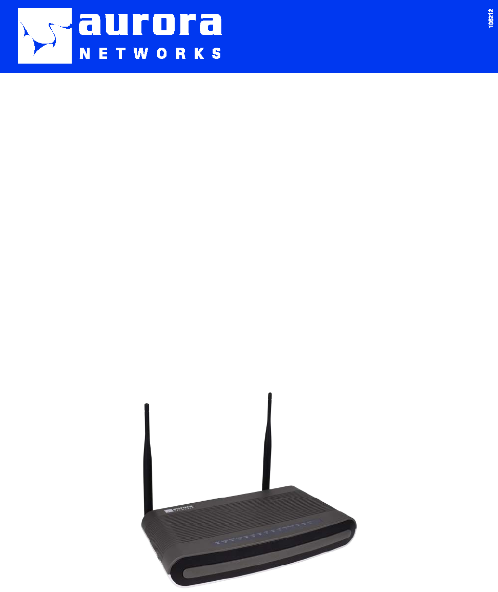
2.1 Overview of ONT-2-E4xxxi Multi-service Residential Gateway Series
The ONT-2-E4xxxi Multi-service Residential Gateway Series of Optical Network Terminals provide
basic and optional features supporting current and future business and consumer connectivity needs for
Data, IPTV including High-definition TV, Voice over IP (VoIP), and Triple-Play services. All ONTs in
the family support the latest Residential Gateway features, including high-speed EPON and
Turbo-EPON communication to the Cable Operator or ISP WAN network, firewall security, efficient
provisioning, and up to 1 Gbps (1000BASE-T) connectivity to four independent LANs on the customer
premise. Optional features for Wi-Fi, Voice over IP, and RF Video Overlay are also available.
The ONT-2-E4021iWn is the full-feature EPON ONT Residential Gateway, featuring a 4-port RJ-45
10/100/1000BASE-T Gigabit Ethernet switch, 2 POTS ports for VoIP, 1 RF Video Overlay port, and
IEEE 802.11n wireless (Wi-Fi) access. The ONT-2-E4020iWn is the same basic unit as the E4021iWn
without the RF Video; the ONT-2-E4021i provides RF Video without Wi-Fi; the ONT-2-E4020i has no
Wi-Fi and RF Video; the ONT-2-E4000i only provides the four 1000BASE-T ports.
See Table 1 for a brief overview of interfaces, ports, VoIP, RF video, Wi-Fi, data, and IPTV services on
each EPON Multi-service Gateway ONT. The various features are described in subsequent sections of
this guide.
Table 1 EPON Multi-service Gateway ONT Supported Services and Features
Multi-service
Gateway ONT Gigabit
Ethernet
(GE) Inter-
faces
POTS Port
VoIP Ser-
vice
RF Overlay
Port
RF Video
Service
Wi-Fi
Service
(Wire-
less)
Data and
IPTV Residential
Gateway (RG)
Features
ONT-2-E4000i 4 0 NA NA X X
ONT-2-E4020i 4 2 NA NA X X
ONT-2-E4021i 4 2 1 NA X X
ONT-2-E4001i 4 NA 1 NA X X
ONT-2-E4020iWn 4 2 NA X X X
ONT-2-E4021iWn 4 2 1 X X X
ONT-2-E4xxxi Multi-service Residential Gateway Series Hardware Installation Guide
8 UNRELEASED DRAFT TM 87-10879 Rev. A
2.2 EPON Multi-service Gateway Series Hardware Interface
This section describes the various hardware interfaces of the ONT.IEEE 802.3ah “First Mile” EPON
Interface
All ONTs in the series feature an a high-speed PON interface to the outside world that is IEEE 802.3ah
EFM (Ethernet First Mile) compliant, supporting bi-directional communications at 2 (2.488) Gbps
downstream and 1 (1.244) Gbps upstream (Turbo-EPON) speeds.
2.2.1 Gigabit Ethernet Ports (1000BASE-T)
All ONTs feature a built-in 4-port 10/100/1000Mbps Ethernet switch that supports four independent
LANs, and features automatic switching between MDI and MDI-X for 10BASE-T, 100BASE-TX and
1000BASE-TX ports. Auto-detection is supported for straight or crossover Ethernet cables.
2.2.2 IEEE 802.11n Wireless Access Point with Support for Secured Access
The ONT-2-E4020iWn and ONT-2-E4021iWn units feature an integrated 802.11n Wireless Access
Point that provides flexible connectivity between wired, wireless, and broadband networks. The Wi-Fi
Protected Access (WPA) and Wired Equivalent Privacy (WEP) features enhance the security level of
data protection and access control via Wireless LAN. The unit is backward compatible with existing and
installed 802.11g and 802.11b equipment. WPS (Wi-Fi Protected Setup) is used for easy establishment
of secured wireless networks.
2.2.3 RF Video Service (RF Overlay)
The ONT-2-E4021i, ONT-2-E4021iWn, and ONT-2-E4001i units support both IP and RF video. The
RF video overlay service on these units enables delivery of both IP and RF video over the same single
fiber as all other services without additional wavelengths.
2.2.4 Voice over IP
ONT-2-E4020i, ONT-2-E4021i, ONT-2-E4020iWn, and ONT-2-E4021iWn units all provide 2 POTS
voice ports with SIP protocol for interoperating with industry-standard VoIP switches. Telephony fea-
tures such as silence suppression, voice activity detection (VAD), comfort noise generation (CNG), echo
cancellation, call waiting, call transferring, and Caller ID (CID) are included. A broad range of codecs
and standard telephones can be used with the ONT. T.38 Fax transmission and Fax pass-through modes
of operation also are supported.
2.3 Supported Residential Gateway (RG) Features
All ONT-2-E4xxxi Multi-service Residential Gateway Series support the following Residential Gate-
way features.
2.3.1 Network Address Translation (NAT)/NAPT (Network Address Port Translations)
NAT and NAPT (Network Address Port Translation) simultaneously allow multiple users to access
outside resources (such as the Internet) with one IP address/one Internet access account.
ONT-2-E4xxxi Multi-service Residential Gateway Series Hardware Installation Guide
TM 87-10879 Rev. A UNRELEASED DRAFT 9
2.3.2 Dynamic Domain Name System (DDNS)
A DNS Relay provides an automatic way to associate a domain name (a user-friendly name such as
www.yahoo.com) and IP address of a service or device. When a local machine sets its DNS server with
this relay’s IP address, every DNS conversion request packet from the PC to this gateway will be for-
warded to the real DNS in the outside network.
The DDNS service allows you to alias a dynamic IP address to a static hostname. This dynamic IP ad-
dress is the WAN IP address. For example, to use the service, you must first apply for an account from a
DDNS service, such as http://www.dyndns.org/. More than five (5) DDNS servers are supported.
2.3.3 Dynamic Host Configuration Protocol (DHCP) Client and Server
As part of the Residential Gateway features, the ONT includes a DHCP server that can serve IP ad-
dresses to CPEs attached to the LAN ports. From the WAN side, the ONT’s DHCP client can obtain a
WAN IP address directly from the Internet Service Provider (ISP) automatically. For LAN-attached
customer devices, the DHCP server in the ONT can allocate a range of client IP addresses and distribute
them, including IP address and subnet mask, as well as DNS IP address to local computers. Layer 2
DHCP relay (with Option 82) is also supported.
2.3.4 Security Firewall and Rich Packet Filtering
A firewall with rich packet filtering process not only filters the packet based on an IP address, but also
based on Port numbers. Packets will be filtered from and to the Internet, providing a higher level of
security control.
2.3.5 Advanced Quality of Service,
The ONT-2-E4xxxi Multi-service Residential Gateway Series supports advanced QoS features, in-
cluding rate limiting on a per port basis, bandwidth management, and Traffic Prioritization based on
Layer 2 Class of Service (802.1p) and Layer 3 DiffServ markings.
2.3.6 Virtual Server
Users can specify services to be visible from the WAN side of the EPON Multi-service Gateway. The
gateway can detect incoming service requests and forward either a single port or a range of ports to the
specific local computer for dispensation. For example, a user can assign a PC in the LAN acting as a
WEB server inside and expose it to the outside network. Outside users can browse inside web servers
directly while it is protected by NAT. A DMZ host setting is provided to a local computer exposed to the
outside network.
2.3.7 Flexible Management Interfaces including Web GUI
The ONT supports Ethernet OAM per IEEE 802.3 specifications through flexible management inter-
faces with LAN and WAN ports. Users can use Telnet, Web GUI, and SNMP through the WAN and
LAN ports to configure and manage the device. Support for Trident7 EMS is built in for service provi-
sioning and management of data, IPTV video, and VoIP services. Provisioning of Wi-Fi and RG services
are supported through a separate Web-based GUI interface. The device can be upgraded to the latest
firmware remotely through the Web-based GUI and/or the Trident7 EMS.

ONT-2-E4xxxi Multi-service Residential Gateway Series Hardware Installation Guide
10 UNRELEASED DRAFT TM 87-10879 Rev. A
2.4 Additional Features
• The aesthetically-pleasing enclosure features a streamlined compact design, with an optimized
rear access for a physically-secure fiber PON port.
• All connectors are on the rear-side of the unit. Connections include four (4)
10/100/1000BASE-T data, two (2) POTS, a backup power, and an 12 VDC input. A USB port is
reserved for future use.
• A separately sold, thin, modular fiber slack management tray, when mounted underneath the
unit, securely hides excess fiber and protects it from potential abuse or destruction.
• All ONTs support desk or wall mount or vertical (tower) mount installations.
• LED Indicators—Ample LED indicators are available and conveniently located on the
top-front of the unit, easily in view by the user to monitor important status information. See the
LED indicator action descriptions the Product Specification Section.
2.5 Product Specifications
Table 2 provides a summary of the features and product specifications for the ONT-2-E4xxxi Mul-
ti-service Residential Gateway Series.
Table 2 Product Specifications for ONT-2-E4xxxi Multi-service Residential
Gateway Series
Function/Parameter Unit ONT-2-E4000i ONT-2-E4020i
ONT-2-E4021i &
ONT-2-E4001i ONT-2-E4020iWn ONT-2-E4021iWn
Network Interface
Optical Interface SC/APC
Fiber Type G.652 Single-mode
Transmit Wavelength nm 1310 ±20
Transmit Launch Power
(min-max) dBm +0.5 to 5.0 +0.5 to 5.0 +0 to 5.0 +0.5 to 5.0 +0 to 5.0
Transmit Spectrum Width nm 1
Receive Wavelength (Data) nm 1490 ±10
Receive Wavelength (RF Vid-
eo) nm ̶ ̶ 1555 ±10 ̶ 1555 ±10
Receive Sensitivity @1490
(min-max) (measured with a PRBS
223-1 test pattern @2.488 Gbps and ER=
10dB = 10-10)
dBm -8 to -28
Receive Sensitivity @1550nm
(min-max) (linear operating
range) dBm ̶ ̶ -8 to +2 ̶ -8 to +2
1550 nm Optical Isolation
(1400 - 1500 nm)(min) dB ̶ ̶ 30 ̶ 30
Receive Overload @ 1550nm
(min) dBm ̶ ̶ +5 ̶ +5
Downstream/Upstream Rate Gbps 2.488/1.244 Turbo Mode
Telephony

ONT-2-E4xxxi Multi-service Residential Gateway Series Hardware Installation Guide
TM 87-10879 Rev. A UNRELEASED DRAFT 11
Function/Parameter Unit ONT-2-E4000i ONT-2-E4020i
ONT-2-E4021i &
ONT-2-E4001i ONT-2-E4020iWn ONT-2-E4021iWn
Analog POTS
Ports/Connectors
(none on ONT-2-E4001i) ̶ 2-RJ-11
REN REN ̶ 4
Data
Wi-Fi (2 Antennas) ̶ ̶ ̶ IEEE 802.11b/g/n,
Max antenna gain
+5dBi
IEEE 802.11b/g/n,
Max antenna gain
+5dBi
Ethernet Ports/Connectors
(10/100/1000BASE-T) 4-RJ45
RF Overlay
RF Video Ports/Connectors ̶ ̶ 1 F-Type ̶ 1 F-Type
RF Video Output Bandwidth Mhz ̶ ̶ 47 - 870 ̶ 47 - 870
RF Output Level dBmV ̶ ̶ +17 ̶ +17
RF Output Tilt (typ/max) dB ̶ ̶ 2/5 v 2/5
2.6 Physical Characteristics
Table 3 provides a summary of the physical specifications of the ONT-2-E4xxxi Multi-service Resi-
dential Gateway Series.
Table 3 Physical Characteristics for ONT-2-E4xxxi Multi-service Residential
Gateway Series
Function/Parameter Unit E4000i E4020i E4021i &
E4001i
E4020iWn E4021iWn
Physical, Temperature, and Humidity Characteristics
Dimensions (W x H x D) in. 10.24 x 6.22 x 1.7
mm 260 x 158 x 43
Weight
lbs.
1.1
g
500
Operating Temperature
F
+32 to +104
C
0 to +40
Storage Temperature
F
-4 to +158
C
-20 to +70

ONT-2-E4xxxi Multi-service Residential Gateway Series Hardware Installation Guide
12 UNRELEASED DRAFT TM 87-10879 Rev. A
Function/Parameter Unit E4000i E4020i E4021i &
E4001i
E4020iWn E4021iWn
Humidity - Operating
%
+10 to +90
Humidity – Storage
%
+5 to +95
Power Characteristics
Input Voltage (100 - 240 V
AC
Adapter Supplied)
V
DC
12
Power Consumption (Maximum)
W
8.5
18
18
18
18

ONT-2-E4xxxi Multi-service Residential Gateway Series Hardware Installation Guide
TM 87-10879 Rev. A UNRELEASED DRAFT 13
Chapter 3 Hardware Description
This chapter describes the package contents, accessories, the ONT enclosure, LED indicators used for di-
agnostics, power adapter, and types of interfaces on the EPON Multi-service Gateway ONT.
Note: Figures in the description of the product are for reference only.
3.1 Package Contents
The following product items are shipped as part of the package contents.
Table 4 Package Contents for ONT-2-E4xxxi Multi-service Residential Gateway Se-
ries
Item
Part Number
Description
ONT-2-E4xxxi-** or
ONT-2-E4xxxiWn-**
Where ** is one of the following:
-US United States
-UK United Kingdom
-EU Europe
-AU Australia
EPON Multi-service Residential
Gateway ONT.
Power adapter The appropriate power adapter, compatible
with the ONT part number selected, will be
shipped as part of the package.
Four power adapter options, based
on the ONT part number options.
Note: The ONT-2-E4020iWn and ONT-2-E4021iWn have two attached antennas. Do not attempt to detach
the antennas.
CAUTION!
• This ONT is for indoor use only.
• Only use the power adapter that comes with the product. Using a different voltage rating
power adapter may damage the ONT.
• Do not open the case of the EPON Multi-service Gateway ONT. The exception is the
protected PON compartment may be opened. There are no customer-serviceable parts
inside the unit. If the ONT needs repair, contact the appropriate service provider for re-
placement instructions.
3.2 Accessories
The following are accessories that compliment the EPON Multi-service Gateway ONT and may be ordered
separately from Aurora Networks.

ONT-2-E4xxxi Multi-service Residential Gateway Series Hardware Installation Guide
14 UNRELEASED DRAFT TM 87-10879 Rev. A
Table 5 Orderable Accessories for ONT-2-E4xxxi Multi-service Residential Gateway
Series
Accessory Name Part
Number
Description Image
Fiber storage tray
with cover To be added. The tray is used to store the optical
fiber cable. The tray can be
wall-mounted with the cable inside;
when the ONT has been provi-
sioned, the ONT can be quickly
snapped in the tray.
Tower stand To be added. The tower stand is used for vertical
or tower mounting.
3.3 ONT-2-E4xxxi Multi-service Residential Gateway Series Enclosure
The EPON Multi-service Gateway ONTs are similar across the series. The ONT-2-E4xxxi Mul-
ti-service Residential Gateway Series is designed for inside building customer premises and/or inside
plant environments. It can be placed on a desktop, or tower-mounted, or wall-mounted via keyhole slots
that are built into the bottom of the unit. It has an optional fiber tray for slack management of the video
fiber cable. Once the fiber tray is wall-mounted, the ONT can be easily and quickly snapped in any time.
It also has an optional tower bracket for tower-mounting (vertical mounting).
The front of the EPON Multi-service Gateway houses the system LED status indicators for Power,
Backup Power, EPON port, Alarm, WAN, four (4) LAN Gigabit Ethernet ports, two (2) telephone ports,
Voice over IP (VoIP) service, Wi-Fi, WPS, USB, and RF connectivity. Refer to Figure 1 for the location
of LED indicators on an example ONT-2-E4020iWn unit.
Note that the ONT-2-E4000i and ONT-2-E4001i do not have telephone ports. The ONT-2-E4020iWn
and ONT-2-E4021iWn have wireless (Wi-Fi) access points that offer high speed wireless connectivity
with built-in antennas. Only the ONT-2-E4021i and ONT-2-E4021iWn have RF Overlay capability.
3.4 LED Diagnostics on Front Panel
The LED status indicators are on the top of the front of the EPON Multi-service Gateway ONT. The LEDs
can be used to diagnose the status of the ONT. See Figure 1 for a view of LED indicators on an
ONT-2-E4xxxi Multi-service Residential Gateway Series.

ONT-2-E4xxxi Multi-service Residential Gateway Series Hardware Installation Guide
TM 87-10879 Rev. A UNRELEASED DRAFT 15
Figure 1 LED Indicators on EPON Multi-service Gateway ONT
See Table 6 for a description of the LED indicators located on the front top of an EPON Multi-service
Gateway ONT.
Table 6 LED Indicators and Descriptions
LED
Color
Status
Description
PWR (Power) or
SYS (System)
Green-Blinking Blinks Booting up.
Green-Solid On ONT is operating.
Backup Power
Dark Off No backup power is present.
Green-Solid On Backup power is present.
Green-Blinking On
Slow blinking green when ONT is running on backup
power.
Fast blinking green when a problem exists with the
backup power.
EPON
Dark On No fiber uplink to EPON interface or failed to connect
over EPON network.
Green-solid On PON uplink is OK, and EPON network connection is
operational.
Alarm Dark Off No alarm condition exists.
Red-Blinking Blinks Alarm condition exists.
WAN (Internet)
Dark Off No fiber uplink to EPON interface or ONT model is
configured by Service Provider so that it does not have
a routed connection to the internet.
Green-Blinking Slow Blink During DHCP, ONT failed to receive an IP address
from the service provider.
Green-solid On ONT is connected to the WAN.

ONT-2-E4xxxi Multi-service Residential Gateway Series Hardware Installation Guide
16 UNRELEASED DRAFT TM 87-10879 Rev. A
LED
Color
Status
Description
LAN1, LAN2,
LAN3, LAN4
(Data Link/Activity)
Dark Off No link has been established at the LAN interface, or
the interface is administratively disabled by the service
provider.
Green-Solid On LAN port is up.
Green-Blinking Blinks Data is being transmitted or is received.
VoIP
(all models except
ONT-2-E4000i)
Dark Off
The ONT has failed to register with the Call Agent (SIP
server), or
Voice services have not been provisioned.
Green-Blinking Blinks To be determined.
Green-Solid On To be determined.
Voice Diagnostics:
Phone1
Phone2
(all models except
ONT-2-E4000i)
Dark Off
There is no phone is connected to the indicated line, or
The phone port is disabled, or
The phone port is enabled, but the attached phone is
on-hook.
Green-solid On To be determined.
WiFi (Wireless)
(ONT-2-E4020iWn
ONT-2-E4021iWn)
Green-Solid On A wireless connection is established via the web GUI.
Green-Blinking Blinks Data is being transmitted or is received.
WPS Dark Off WiFi Protected Setup (WPS) – status to be determined.
USB Dark Off Reserved for future use.
RF
(for RF-capable
models:
ONT-2-E4021i,
ONT-2-E4021iWn)
Dark Off RF video is disabled.
Green-solid On RF video is enabled with 1550 nm RF output.
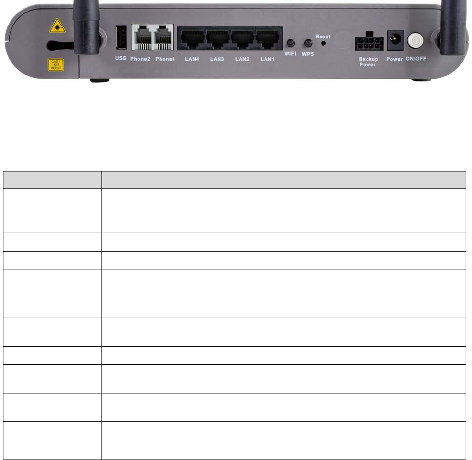
3.5 Rear Panel and Interface Description
Ports on the ONT-2-E4xxxi Multi-service Residential Gateway Series are located on the rear panel. See
Figure 2 for a picture of the ports on an ONT-2-E4020iWn.
ONT-2-E4xxxi Multi-service Residential Gateway Series Hardware Installation Guide
TM 87-10879 Rev. A UNRELEASED DRAFT 17
Figure 2 Rear Panel Ports on the ONT-2-E4020iWn
The following table describes the ports and interfaces on the rear panel of the ONT-2-E4020iWn. For a de-
scription of the PON optical fiber connector, see Figure 3 SC/APC Optical Fiber Plugged into Optical
Network Interface.
Table 7 Rear Panel Ports on the ONT-2-E4020iWn
Interface
Description
ON/OFF Power ON/OFF switch. Depress button to turn on. Power off the device when it is not in use,
for power saving.
CAUTION: Beware of accidentally pressing this button—it will turn off the ONT.
Power
Connect to the supplied power adapter.
Backup Power Connect to an external power supply.
Reset Restore to factory defaults. If you power on the device and use a thin needle to press the
Reset button for over 1 second, the ONT is automatically reset and is restored to the factory
default settings.
If you cannot log in to the ONT or forget your username/password, press this
button for more than 6 seconds to restore to defaults.
WPS Press to activate Wi-Fi Protected Setup (WPS) for a period of time. Activating WPS in this
manner may override your disabling WPS via the GUI interface.
WiFi Reserved for future use.
LAN1, LAN2, LAN3,
LAN4
RJ-45 Ethernet interface with the self-adaptive rate of 10/100/1000 Mbps, for connecting to
the local network.
Phone1
Phone2 Connect these two voice ports to an analog phone set with a RJ-11 cable.
USB Reserved for future use. In the future, the standard USB connector will accommodate back
up of local configuration data and firmware updates via mass storage media, such as a flash
drive.
3.6 Ethernet Connections
The ONT-2-E4xxxi Multi-service Residential Gateway Series provides four switched Ethernet
10/100/1000 Base-T RJ-45 copper wire twisted pair interfaces for direct connection to a PC or Ethernet
set top box, or indirect connection to other Ethernet equipment via an attached switch, hub, or router.
All Ethernet ports are “switched” interfaces, meaning that each port can act as part of a separate inde-
pendent network segment, hence video or data traffic can be restricted to the port for which it is in-
tended.
ONT-2-E4xxxi Multi-service Residential Gateway Series Hardware Installation Guide
18 UNRELEASED DRAFT TM 87-10879 Rev. A
The IEEE 802.3x-compliant gigabit Ethernet 10/100/1000Base-T interfaces auto-detect whether the
connecting cable is a straight-through or cross-over type and configure themselves accordingly. In ad-
dition, the interfaces auto-negotiate (by default) to match the speed of the remote device.
The link length can be no greater than 100 m (≈328 ft), which is the Ethernet standard.
3.7 EPON SC/APC Fiber Optic Network Interface
The ONT-2-E4xxxi Multi-service Residential Gateway Series supports one EPON optical interface via an
SC/APC connector located on the left-side rear panel for the Network Interface (NI) connection. This in-
terface accepts a single mode fiber terminated with an SC/APC connector. The SC/APC PON connector is
smartly enclosed by a small plastic removable cover that, when snapped into place, protects the connector
from becoming dislocated or separated from the ONT. See Figure 3 for the optical fiber connector location,
where the fiber is shown routed through the smaller aperture for wall mounting.
Figure 3 SC/APC Optical Fiber Plugged into Optical Network Interface
A small screw located in the unit holds the cover in place. The network connector and network EPON fiber
must be wired to the premises by the service provider or contractor in an appropriate location before the
EPON Multi-service Gateway ONT can be installed.
The ONT-2-400i supports an UPC connector, not an APC connector. UPC connectors are blue in color.
3.8 Voice Telephony Interfaces (Standard Telephone)
The ONT-2-E4020i, ONT-2-E4021i, ONT-2-E4020iWn, and ONT-2-E4021iWn provide two independent
standard analog voice ports. The voice ports are commonly known as Plain Old Telephone Service (POTS)
ports. These connections provide toll quality voice through a Voice over IP (VoIP) connection. Refer to
Figure 2 for the location of the telephone connectors, labeled “Phone1” and Phone2.” The voice ports on the
ONT use RJ-11 modular jacks, with one line per jack, wired in a standard two-wire configuration.
You can attach a standard household telephone to these ports to make voice calls. Call setup and signaling is
provided via the Session Initiation Protocol (SIP) for interoperating with industry standard VoIP switches,
and analog voice data is converted to IP packets for transmission over the service provider’s network. The
ONT-2-E4020i, ONT-2-E4021i, ONT-2-E4020iWn, and ONT-2-E4021iWn support a wide variety of te-
Note

ONT-2-E4xxxi Multi-service Residential Gateway Series Hardware Installation Guide
TM 87-10879 Rev. A UNRELEASED DRAFT 19
lephony features, such as silence suppression, voice activity detection, comfort noise generation, echo can-
cellation, call waiting, call transferring, and Caller ID.
A broad range of codecs is supported. FAX Transmission with T.38 fax relay and G.711 pass-through are
also supported modes of operation.
The RJ-11 POTS (Standard Telephone) ports support a REN (Ringer Equivalency Number) load of four (4).
3.9 RF Overlay
The ONT-2-E4021i and ONT-2-E4021iWn have RF Overlay capability. These two ONTs support an RF port
for delivery of a full spectrum of broadcast RF video services over 75 Ohm RG-6 coaxial cable.
3.10 Power
The EPON Multi-service Gateway ONT is shipped with an AC/DC power adapter that accepts a rated input
voltage of 100-240 volts AC and provides an output voltage of 12 VDC to the ONT. The EPON Multi-service
Gateway ONT has a minimum input current rating of 1.5 AMPS. The power adapter (also referred to as
power supply) shipped with the ONT is equipped with an AC plug that is suitable for the country or region of
sale.
The EPON Multi-service Gateway ONT supports a backup power connector in the rear panel of the ONT that
is marked as a “Backup Power” connector. The backup power connector is an 8-pin connector. It is intended
for a backup power supply with alarm inputs. See Figure 4 for a closeup of the Backup Power connector in
the rear panel of the ONT.
Figure 4 Rear Backup Power Connector
The EPON Multi-service Gateway ONT also supports an additional backup power connector on the side.
This backup power connector is reserved for a future feature. See Figure 5 for a closeup of the side backup
power connector.
Figure 5 Side Backup Power Connector
Note
ONT-2-E4xxxi Multi-service Residential Gateway Series Hardware Installation Guide
20 UNRELEASED DRAFT TM 87-10879 Rev. A

ONT-2-E4xxxi Multi-service Residential Gateway Series Hardware Installation Guide
TM 87-10879 Rev. A UNRELEASED DRAFT 21
Chapter 4 Installing the ONT-2-E4xxxi
Multi-service Residential Gateway Series
Installation of the ONT-2-E4xxxi Multi-service Residential Gateway Series consists of the following pro-
cedures:
1. Unpacking the ONT
2. Installing and mounting the ONT.
The EPON Multi-service Gateway ONT can be wall-mounted, tower-mounted (vertical mounting), or
placed on a desk.
3. Connecting service provider cabling (the EPON network cable)
4. Connecting the premises wiring (POTs and Ethernet)
5. Connecting the power
6. Activating and powering up the ONT
We recommend you perform the steps in the order presented.
After you have completed the installation of the EPON Multi-service Gateway ONT, see the section
“Connecting to the GUI Interface of the ONT” for information on using the ONT’s GUI interface to con-
figure, in particular, the Residential Gateway functions on all of the ONTs in the ONT-2-E4xxxi Mul-
ti-service Residential Gateway Series and Wi-Fi (wireless) capabilities on the ONTs that support Wi-Fi.
4.1 Cautions and Warnings
Follow all warnings, cautions, and required actions when working with the EPON Multi-service Gateway
ONTs.
CAUTION: Telephone and telephony devices connected to the EPON Multi-service Gateway
must comply with FCC Part 68 Class A and have appropriate approvals and labeling.
CAUTION! Class 1 Laser Radiation–Avoid any exposure to laser beams.
4.2 Pre-Installation Check
For successful installation of the ONT-2-E4xxxi Multi-service Residential Gateway Series, ensure that you
have all the necessary equipment and account information set up for subscriber services.
Your Cable Operator or Service Provider must provide a fiber optic drop cable that is terminated with an
SC/APC connector in order to utilize the EPON network services.
See Section 3.1 Package Contents and Section 3.2 Accessories for a list of products shipped in the package
and types of accessories that can be ordered for the ONT-2-E4xxxi Multi-service Residential Gateway Se-
ries.
ONT-2-E4xxxi Multi-service Residential Gateway Series Hardware Installation Guide
22 UNRELEASED DRAFT TM 87-10879 Rev. A
4.3 Tools and Materials Needed
The following tools and materials may be needed to install the EPON Multi-service Gateway ONT:
• Fiber optic splicing tools (if required to connect a pigtail fiber).
• Fiber optic connector cleaning tool.
• If wall mounting the unit, appropriate nails or screws to act as mounting posts and a hammer or
screwdriver as needed.
4.4 System Requirements
Before installing the device, check the following items:
1. Service subscription
You need to apply for service to your Internet service provider (ISP), and access services provided by
your ISP by using the PON access (broadband access) mode. Your ISP must provide at least one valid IP
address for you (static or dynamic allocation).
2. Hardware configuration
Ensure that a 10/100/1000 Mbps Ethernet card or an 802.11b/g/n wireless network card is installed in
your computer or that you have a network device that provides a 10/100 Mbps Ethernet interface.
Ensure that computers that need to access the network are equipped with the network card driver and the
TCP/IP protocol. Correct network setting is also required.
3. Operating system
Operating systems can be Windows 98SE, Windows ME, Windows 2000, Windows XP, or Windows 7.
For system configuration in the web interface, the browser should be Internet Explorer V6.0 or later.
The following equipment and associated service account information must be available for the EPON Mul-
ti-service Gateway ONT to operate:
• For data services
Up to four (4) personal computers or Ethernet switches with 10/100/1000BASE-T network
adapters and RJ-45 physical connectors installed.
Up to 100 meters of Cat5, Cat5E, or Cat6 copper Ethernet cable, with RJ-45 connectors at
each end.
An Ethernet hub or wired/wireless router can be used to extend connectivity beyond the four
direct connections coming from the ONT.
An account for data services must be established by the Cable Operator or Service Provider.
• For IPTV video services
At least four (4) Ethernet set top boxes can be connected directly to the ONT.
All subscriber video services must be pre-provisioned by the video service provider.
• For IP telephone services (except the ONT-2-E4000i has no voice ports)
Up to two (2) standard analog telephones can be connected to the ONT, using the standard
RJ-11 telephone connector.
All subscriber phone services including any available calling features must be pre-provisioned by the
Cable Operator or Service Provider.
ONT-2-E4xxxi Multi-service Residential Gateway Series Hardware Installation Guide
TM 87-10879 Rev. A UNRELEASED DRAFT 23
4.5 Situating the EPON Multi-service Gateway ONT
The ONT-2-E4xxxi Multi-service Residential Gateway Series is designed to accommodate desktop, wall,
or tower mounting. If the unit is to be placed on a desktop or other flat surface, make sure that the
surface is stable. You should also ensure that you select a location which allows easy access to the rear
of the unit for wiring and testing purposes.
There must be an AC electrical outlet close by for the power adapter. This outlet should be dedicated for
the EPON Multi-service Gateway ONT. It is recommended to not have multiple EPON Multi-service
Gateway ONTs sharing the outlet by means of a power strip, because emergency voice services for
multiple users can be affected in the event of a power strip failure. Be sure that you only use the power
adapter included in the package.
The ONT-2-E4xxxi Multi-service Residential Gateway Series is designed for operation in a dry room
temperature indoor environment. Do not use it outdoors, or in a location with excessive heat or hu-
midity.
4.6 Wall-Mounting the ONT Using the Fiber Tray
The fiber storage tray is used for slack management of the optical fiber cable. The fiber tray can also be used
as a mounting bracket for the EPON Multi-service Gateway ONT for interior installations. After the field
technician mounts the fiber tray, the fiber tray cover is snapped in place. Then the EPON Multi-service
Gateway ONT can be snapped into the fiber tray any time when the service for the ONT is ready to be turned
on.
To wall-mount an EPON Multi-service Gateway ONT by installing the fiber tray, we recommend the fol-
lowing procedure:
1. Ensure that the location of the EPON Multi-service Gateway ONT is within reach of a suitable AC
outlet. The power cord on the AC adapter is approximately 5 ft. (1.52 m) long.
2. Select a flat, rigid mounting surface to wall-mount the fiber tray.
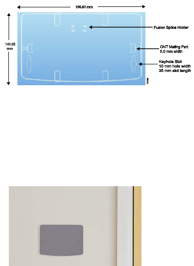
3. Note the keyhole slots in the back of the fiber tray that are available for wall hanging. See Figure 6.
ONT-2-E4xxxi Multi-service Residential Gateway Series Hardware Installation Guide
24 UNRELEASED DRAFT TM 87-10879 Rev. A
Figure 6 Schematic of the Back of the Fiber Tray
4. Select 2 screws or nails (with heads appropriately sized to snugly fit the keyhole slots), and insert them
into the wall so that they align with the keyhole slots. Ensure that the screw/nails are horizontally level.
5. When the screws are in place and the fiber tray is ready to be mounted, hold the fiber tray so that its
keyhole slots are positioned directly over the screw heads, push it back towards the wall, and then slide it
downward until it is firmly seated in place.
Snap the fiber tray cover over the fiber tray. You can wire the optical fiber cable any time. See Figure 7
for a picture of a fiber tray that has been mounted on a wall, in preparation for a provisioned EPON
Multi-service Gateway. Remove the fiber tray cover and deftly snap the ONT onto the tray.
Figure 7 Fiber Tray with Cover Installed on Wall
6. When the EPON Multi-service Gateway ONT has been provisioned for service, you can place the ONT
onto the fiber tray by holding the ONT with the Aurora Networks logo on top and snapping the ONT
onto the fiber tray.
ONT-2-E4xxxi Multi-service Residential Gateway Series Hardware Installation Guide
TM 87-10879 Rev. A UNRELEASED DRAFT 25
Figure 8 EPON Multi-service Gateway Wall-mounted onto Fiber Tray
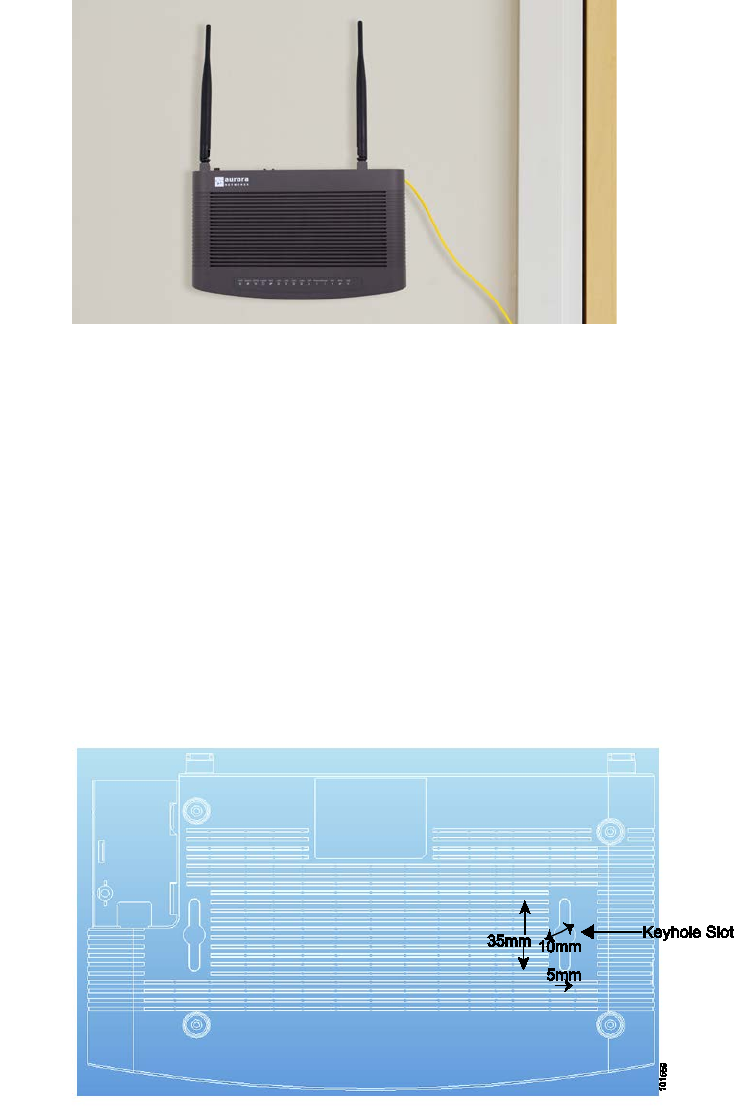
4.7 Wall-Mounting the ONT without the Fiber Tray
To wall-mount an EPON Multi-service Gateway ONT without installing the fiber tray, we recommend the
following procedure:
1. Ensure that the location of the EPON Multi-service Gateway ONT is within reach of a suitable AC
outlet. The power cord on the AC adapter is approximately 5 ft. (1.52 m) long.
2. Select a flat, rigid mounting surface to wall-mount the EPON Multi-service Gateway ONT.
3. Turn the ONT unit upside down and note the keyhole slots which are available for wall hanging.
Figure 9 Schematic of the Bottom of EPON Multi-service Gateway
4. Select 2 screws or nails (with heads appropriately sized to snugly fit the keyhole slots), and insert them
into the wall so that they align with the keyhole slots. Ensure that the screw/nails are horizontally level.
ONT-2-E4xxxi Multi-service Residential Gateway Series Hardware Installation Guide
26 UNRELEASED DRAFT TM 87-10879 Rev. A
5. When the screws are in place and the unit is ready to be mounted, hold the ONT (with the Aurora
Networks logo on top) so that its keyhole slots are positioned directly over the screw heads, push it back
towards the wall, and then slide it downward until it is firmly seated in place.
Figure 10 EPON Multi-service Gateway Wall-mounted
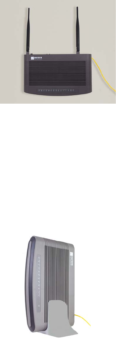
4.8 Vertical or Tower Mounting the ONT
You might want to vertically mount your EPON Multi-service Gateway ONT, instead of installing it on your
desk, to save space. To vertically mount or tower mount an ONT, we recommend the following procedure:
1. Ensure that the location of the EPON Multi-service Gateway ONT is within reach of a suitable AC
outlet. The power cord on the AC adapter is approximately 5 ft. (1.52 m) long.
2. Select a flat, stable surface. Ensure that you select a location which allows easy access to the rear of
the unit for wiring and testing purposes.
3. Place the tower stand on the flat surface and carefully drop the EPON Multi-service Gateway ONT into
the tower stand. See Figure 11 for a picture of a vertically-mounted (or tower-mounted) ONT.
Figure 11 EPON Multi-service Residential Gateway ONT Vertically-Mounted
ONT-2-E4xxxi Multi-service Residential Gateway Series Hardware Installation Guide
TM 87-10879 Rev. A UNRELEASED DRAFT 27
4.9 Connecting the EPON Optical Fiber to the ONT
The following procedure should be performed by the service provider or the cable installation contractor.
The EPON Multi-service Gateway ONT has a single SC/APC connector for connecting optical fiber to the
unit. Prior to installation, the service provider or cable installation contractor must have routed and secured
the optical fiber run from the utility pole or conduit, pulled and routed the individual fiber optic cable inside
the premises, installed any wall plate outlets for fiber distribution, and supplied any fiber optic jumper/patch
cable to connect to the EPON Multi-service Gateway ONT. The fiber optic cable (or patch cable) that con-
nects to the Multi-service Gateway must be terminated with an SC/APC connector for a proper connection.
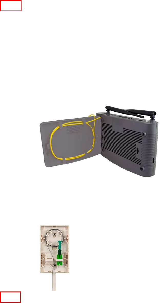
If you obtained the fiber tray, you can wrap the optical fiber cable inside the tray and install the tray on a wall,
in preparation for snapping an EPON Multi-service Gateway onto it. A fiber tray example showing a view of
the optical fiber wrapped in the tray and the ONT poised to be snapped onto the tray is shown in Figure 12.
Figure 12 Snapping the ONT onto the Fiber Tray
A typical wall plate example is shown in Figure 13.
Figure 13 Typical Wall Plate Example
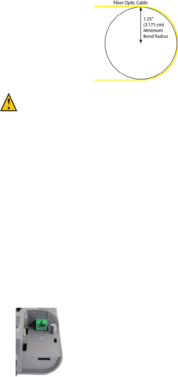
The fiber optic cable should never be bent so that it exceeds its minimum bend radius during installation or
use. Exceeding the bend radius can damage the fiber inside the cable, or reduce performance due to distor-
tion of light along the fiber path. The fiber’s minimum bend radius is 1 ¼ inch (3.175 cm) as shown in Figure
14.
Note
Note
ONT-2-E4xxxi Multi-service Residential Gateway Series Hardware Installation Guide
28 UNRELEASED DRAFT TM 87-10879 Rev. A
Figure 14 Fiber Optic Cable Minimum Bend
CAUTION: Ensure that you inspect and clean every fiber optic connector prior to mating the
fiber ends. Failure to do so may compromise performance of the equipment, or cause
component failure.
Take the following appropriate precautions when inspecting and cleaning fiber optics:
1. Turn off all laser sources
2. Ensure that the cable is disconnected from equipment at both ends of the cable
3. Wear appropriate safety glasses if required
4. Keep unplugged fiber connectors clean by using a protective cap, which is to be stored in a re-sealable
container when not in use.
Refer to document TN-08-001 “Cleaning Fiber Optic Connectors” for more information.
4.9.1 Steps to Connect the Optical Fiber to the ONT
Follow these steps for making connections to the ONT:
1. Remove the protective covers from the tips of the SC optical connector at the end of the jumper or
terminated fiber cable.
2. Insert the SC connector on one end of the cable into the ONT’s SC/APC EPON port, which is located on
the left side of the unit as viewed from the rear. The plastic cover of the SC/APC connector compartment
must first be removed. See Figure 15 for a picture of the optical EPON port with the cover removed.
Figure 15 SC/APC Optical EPON Port
ONT-2-E4xxxi Multi-service Residential Gateway Series Hardware Installation Guide
TM 87-10879 Rev. A UNRELEASED DRAFT 29
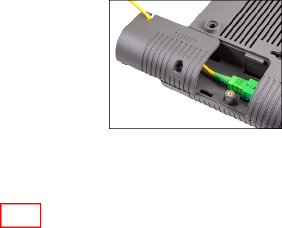
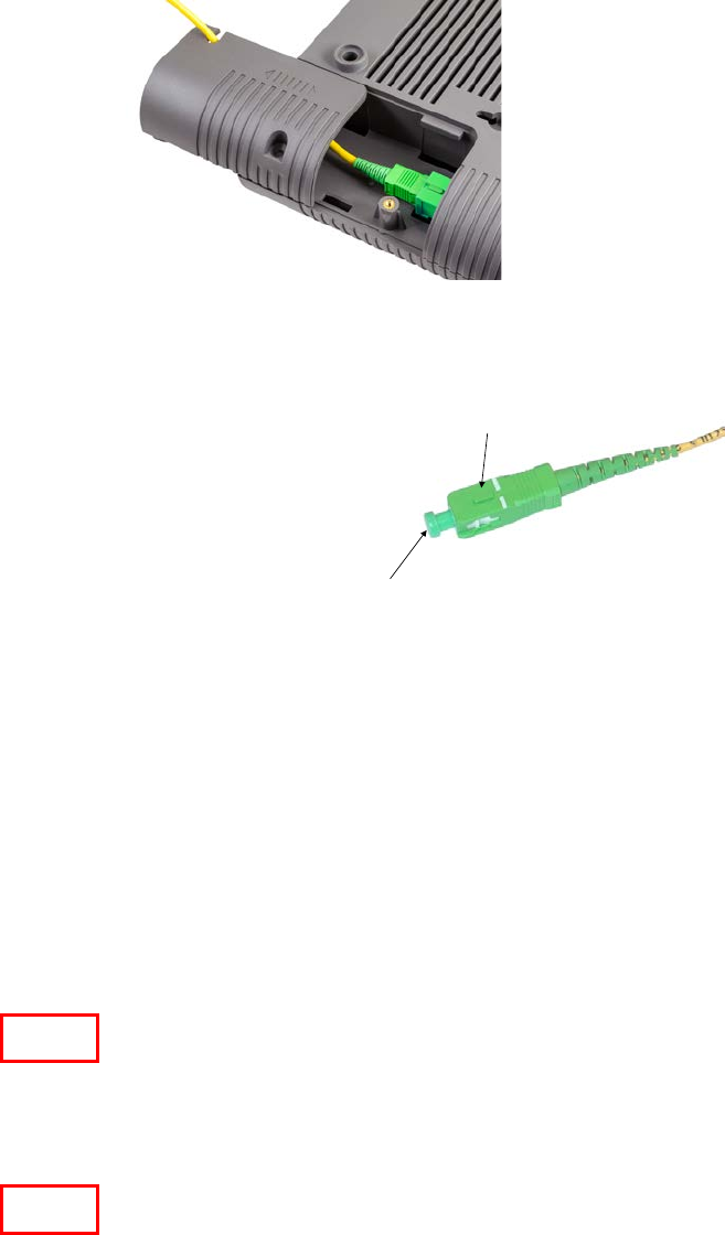
3. See Figure 16 for the location of the SC/APC connector compartment with the optical fiber plugged into
the connector.
Figure 16 SC/APC EPON Connector Compartment
4. Remove the dust cap from the connector and connect the EPON fiber cable to the ONT. The connector is
keyed to prevent mis-insertion into the port. The dust cap should always be left on the connector when
the fiber is not connected to the equipment.
5. Connect the opposite end of the EPON fiber to the wall service connector, which may be similar to that
shown in Figure 13 Typical Wall Plate Example.
6. You can also instead connect the EPON fiber that was wrapped in a fiber tray to the ONT. See an ex-
ample in Figure 12 Snapping the ONT onto the Fiber Tray.
4.10 Connecting Telephones to the EPON Multi-service Gateway ONT
The ONT-2-E4020i, ONT-2-E4021i, ONT-2-E4020iWn, and ONT-2-E4021iWn provide two 6-pin modular
RJ-11 jacks for connecting standard premises telephones. These voice ports each support a REN (Ringer
Equivalency Number) of 4, and a maximum line length of up to 152.4 meters or 500 feet. The Ringer
Equivalency Number is the allowable load for all analog telephony devices (telephones, fax machines, mo-
dems, etc.) on the same incoming line.
The REN value controls the ringer (ringing) of telephones. A ringer equivalency number of 1 represents the
loading effect of a single "traditional" telephone ringing circuit, such as that within the Western Electric Model
500 telephone. Note that the REN of modern telephone equipment may be significantly lower than 1: as a
rough guide, externally-powered digital-ring phones may have a REN as low as 0.1, while modern analog-ring
phones (where the ringer is powered from the phone line) typically have a REN around 0.8.
The REN is indicated on an FCC-Compliance label affixed to the telephony device, and, in the case of internal
modems, generally is indicated in the user documentation.
Dust Cap
Key
Note
Note

ONT-2-E4xxxi Multi-service Residential Gateway Series Hardware Installation Guide
30 UNRELEASED DRAFT TM 87-10879 Rev. A
Follow these steps to connect the telephones or telephony equipment to the EPON Multi-service Gateway
ONT:
1. Telephony equipment is generally supplied with a cable that includes an RJ-11 type plastic connector on
the opposite or both ends. Insert the RJ-11 connector for the first telephone (or other equipment) into the
#1 telephone port (Phone1) located on the rear panel of the EPON Multi-service Gateway ONT.
2. If a second telephony device is to be connected, plug its RJ-11 connector into the #2 telephone port
(Phone2) located on the rear panel of the EPON Multi-service Gateway ONT.
Refer to Figure 2 Rear Panel Ports for the location of the telephone port connectors.
4.11 Connecting Premises LAN Ethernet Wiring
The ONT-E-4020i provides four Ethernet network interfaces.
Each Ethernet Port (LAN1 - LAN4) can be individually mapped to a VLAN as necessary for service de-
ployment.
All Ethernet interfaces auto-detect whether the connectivity cable is straight-through or cross-over and con-
figure themselves accordingly. In addition, all Ethernet interfaces auto-negotiate by default to operate at the
speed and duplex mode of attached devices.
The Ethernet link length can be no greater than 100 m (≈ 328 ft) as defined by the IEEE 802.3 Ethernet
Standard for 10/100/1000BASE-T.
The following steps are an example of how you can directly connect a network interface card, Ethernet set top
box (STB), or an Ethernet switch, hub, or router on the customer premises Local Area Network (LAN). The
service provider or cable operator may provide any site-specific instructions.
1. Use port 1 to connect the household’s primary computer (or switch/router that supports the primary data
services).
2. Ethernet compatible CPEs (computers, switches, routers, etc) utilize standard Ethernet wiring, which
includes an RJ-45 connector on each end of the wire. Plug one end of the Ethernet cable into the target
CPE, and plug the other end of the wire into the Gigabit Ethernet Port #1 on the rear panel of the EPON
Multi-service Gateway ONT. Refer to Figure 2 Rear Panel Ports for the location of the Ethernet ports.
3. Use ports 2, 3, and 4 to connect any remaining Ethernet equipment, such as additional computers,
Ethernet Set Top Boxes, or game controllers with Ethernet ports.
4. To organize the connected cables and reduce stress on the physical connections, it is recommended to
tie-off and strain relieve the cable bundle connected to the rear on the ONT.
5. It is also advisable to label the individual cables noting the CPE and location to which it is connected.
The actual equipment that is connected to ports 1, 2, 3, and 4 may depend on how the Service Provider has
provisioned each port, such as for data or IPTV services.
Note

ONT-2-E4xxxi Multi-service Residential Gateway Series Hardware Installation Guide
TM 87-10879 Rev. A UNRELEASED DRAFT 31
4.12 Connecting Power and Powering Up the ONT
The EPON Multi-service Gateway ONT has a DC power input for connecting to an external 12 volt DC
power supply. Once the power input is connected, the EPON Multi-service Gateway ONT can be powered on
by using the power switch.
Only use the 12 Volt DC power supply and integrated cord that was shipped with the EPON Gateway ONT.
The plug for the power supply is specific to the geographic region in which the EPON Gateway ONT is distrib-
uted.
Follow these steps to connect power and power on the EPON Multi-service Gateway ONT.
1. Make sure the ON/OFF switch is in the OFF position.
2. Ensure that the operational location of the ONT is within reach of a suitable AC outlet. The power cord is
approximately 5 feet (1.52 meters) in length.
3. Connect the power cord to the DC power input connector on the rear of the unit.
4. Plug the power supply into a suitable AC wall outlet.
5. Tie down and strain-relieve the power supply cable to avoid accidental power loss to the unit.
6. Press the ON/OFF switch to ON to apply power to the ONT, and check that the Power LED on the front
of the ONT is green.
See Figure 17 for a closeup of the Backup Power connector in the rear panel of the ONT.
Figure 17 Rear Backup Power Connector
Powering by the Backup Power connector is only effective when the power ON/OFF switch is at the OFF
position.
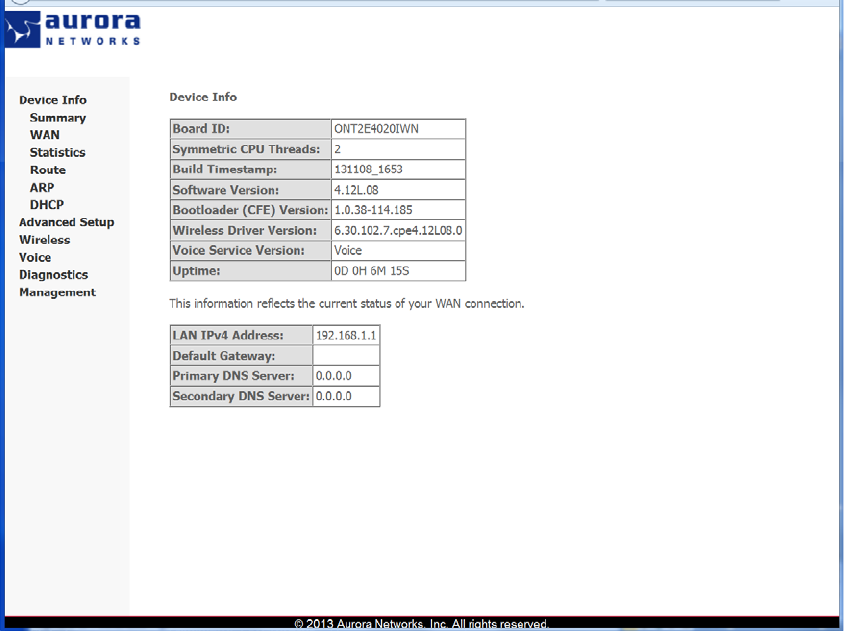
4.13 Connecting to the GUI Interface of the ONT
1. Open your web browser and type http://192.168.1.1 in the browser's address box. This number is the
default IP address for this ONT. Press Enter.
2. A username and password window will appear. The default username and password are “admin” and
“admin” respectively. Press OK to proceed.
3. If the authentication succeeds, the ONT’s GUI homepage “Device Info Summary” screen displays.
Note
ONT-2-E4xxxi Multi-service Residential Gateway Series Hardware Installation Guide
32 UNRELEASED DRAFT TM 87-10879 Rev. A
Figure 18 Device Info Summary Screen

ONT-2-E4xxxi Multi-service Residential Gateway Series Hardware Installation Guide
TM 87-10879 Rev. A UNRELEASED DRAFT 33
Index
1
1000Base-TX · 8
100BASE-TX · 8
10BASE-T · 8
A
accessories · 13
APC connector · 18
audience · 2
Aurora contact information · ii
B
backup power connector, rear · 19
backup power connector, side · 19
bottom, ONT
schematic · 25
C
cautions, laser radiation · 3
chapter summaries · 2
compliance · See
contact us · ii
conventions used in this guide · 1
copyright · ii
D
DDNS · 9
DHCP · 9
documentation, related · 2
documents
obtaining · 2
E
ECO number · ii
enclosure · 14
ethernet connections · 17
Ethernet, LAN
connecting · 30
F
feedback, manual · 3
fiber optic network interface · 18
fiber tray, back
schematic · 23
firewall, security · 9
G
gigabit ethernet
ports · 8
GUI interface · 1, 9
connecting · 31
I
installation instructions · 21
introduction · 1
L
LAN ethernet
connecting · 30
laser radiation warnings · 3
LED diagnostics, front panel · 14, 15
M
manual, related documentation · 2
N
NAT/NAPT · 8
O
optical fiber
connecting · 27, 28
minimum bend ·
optical network interface · 18
optical port
compartment · 29
PON · 28
option 82 · 9
overview · 7
P
package contents · 13
part numbers, ONT · 13
physical characteristic · 11

ONT-2-E4xxxi Multi-service Residential Gateway Series Hardware Installation Guide
34 UNRELEASED DRAFT TM 87-10879 Rev. A
ports, rear panel · 16, 17
POTS ports · 18
power
connecting · 31
power adapter · 19
power adapter, part number · 13
powering up, ONT · 31
pre-installation check · 21
product specifications · 10
product support · 3
Q
QoS
class of service · 9
diffserv markings · 9
R
regulatory compliance · 3
related documentation · 2
REN value · 29
residential gateway · 8
revision date, revision history · ii
RF overlay · 8, 19
RF video
RF overlay · 8
rich packet filtering · 9
S
safety · 3
SC/APC
optical port · 28
SC/APC fiber optic network interface · 18
services, types of · 22
situating, ONT · 23
standards compliance · 3
T
technical manuals · See related documentation
telephone ports · 18
connecting · 30
tools and materials, needed · 22
tower mount, ONT · 26
U
UPC connector · 18
user guides · See related documentation
V
vertical mount, ONT · 26
voice ports · 18
connecting · 29, 30
Voice ports · 8
VoIP · 8
connecting · 30
W
wall mount ONT with fiber tray · 23
wall mount ONT, without fiber tray · 25
wall plate, example · 27
web GUI interface · 9
connecting · 31
web site, Aurora Networks · 2
wireless · 8
wireless access point
IEEE 802.11n · 8
wi-fi · 8