ARRIS Group NVG4XXQ Ethernet and FTTH Gateway User Manual ARRIS NVG46MQ Quick Start Guide
ARRIS Group, Inc. Ethernet and FTTH Gateway ARRIS NVG46MQ Quick Start Guide
Contents
- 1. Users Manual (NVG448BQ).pdf
- 2. Users Manual (NVG468MQ).pdf
Users Manual (NVG468MQ).pdf
Part Number: 599527-001-00
Powering and Initial Cabling
Press the power button on the back of the gateway. The Power indicator will light GREEN to indicate that the gateway is powered correctly. Under
normal operation, while the gateway is powering up, LED status is as follows:
• Internet will light solid BLUE to indicate Internet connection is active, solid RED when there is no IP address, and off when there is no Broadband
connection.
• Broadband, Ethernet, Wireless, and Phone indicators will be off.
• Ethernet and Wireless indicators will light GREEN to indicate that the Ethernet connection and Wireless service are active.
• Broadband indicator will initially flash GREEN, and upon service connectivity, it will light solid GREEN.
• Phone indicator will light GREEN after the Broadband indicator lights GREEN to indicate that digital phone service is active.
NOTE: ATTENTION CATV System Installers. Review section 820-93 of the National Electric Code for proper equipment grounding requirements.
Section 820-93 specifies the Coaxial cable shield must be connected to the building grounding system as close to the point of cable entry as practical.
NOTE: On initial setup, it may take several minutes to achieve service connectivity.
ONT Broadband: Use the following procedure to connect the gateway to Optical Network Termination (ONT) Ethernet.
1. Connect an Ethernet cable to the ONT Broadband port on the back of the gateway.
2. Connect the other end of the Ethernet cable to the incoming ONT connection.
MoCA: Use the following procedure to connect the gateway to a Cable line.
1. Connect a F-Connector terminated coaxial cable to the Cable Line terminal on the back of the gateway.
2. Connect the other end of the coaxial cable from the gateway to the cable service connection.
Digital Phone Service: Use the following procedure to connect the gateway to a digital phone line.
1. Connect the supplied RJ11 terminated phone cable to the Phone port on the back of the gateway.
2. Connect the phone cable to a phone or fax machine.
NOTE: Use a RJ-14 to RJ-11 splitter to connect two phone lines.
Ethernet: Use the following procedure to make an Ethernet connection on the gateway.
1. Connect the supplied RJ45 terminated Ethernet cable to one of the Ethernet ports on the back of the gateway.
2. Connect the Ethernet cable to the Ethernet port on a local computer.
Access the Web Management Interface
1. Open a web browser, such as Firefox, Chrome, or Microsoft Internet Explorer, from the computer connected to the gateway.
2. Type the following address in the address bar of the browser to open the Access Code Required Screen:
http://192.168.254.254
Access the Web Management Configuration Pages
NOTE: When applicable, select the appropriate language button in the lower right corner of the Access Code Required Screen to continue in the
selected language.
To access the Web Management configuration pages:
1. Provide the Device Access Code, a unique code printed on a label on the base of the gateway.
2. Select Continue.
Broadband Configure Interface
The NVG468MQ has Broadband Configuration screen for initial configuration. Use the Broadband Configuration screen to configure the gateway to use
DHCP Client or PPPoE for the broadband IP interface:
• If the proper connection type is not determined, use the DHCP option from the pulldown menu and select Finish.
• If it is known that PPPoE is required, then select it and enter the user name and password, then select Finish. When the connection is successful,
the Home Screen opens.
• If there is a failure in the connection, the notice “WAN connection was not successful - Please reenter your broadband configuration” appears
on the Broadband Configuration screen.
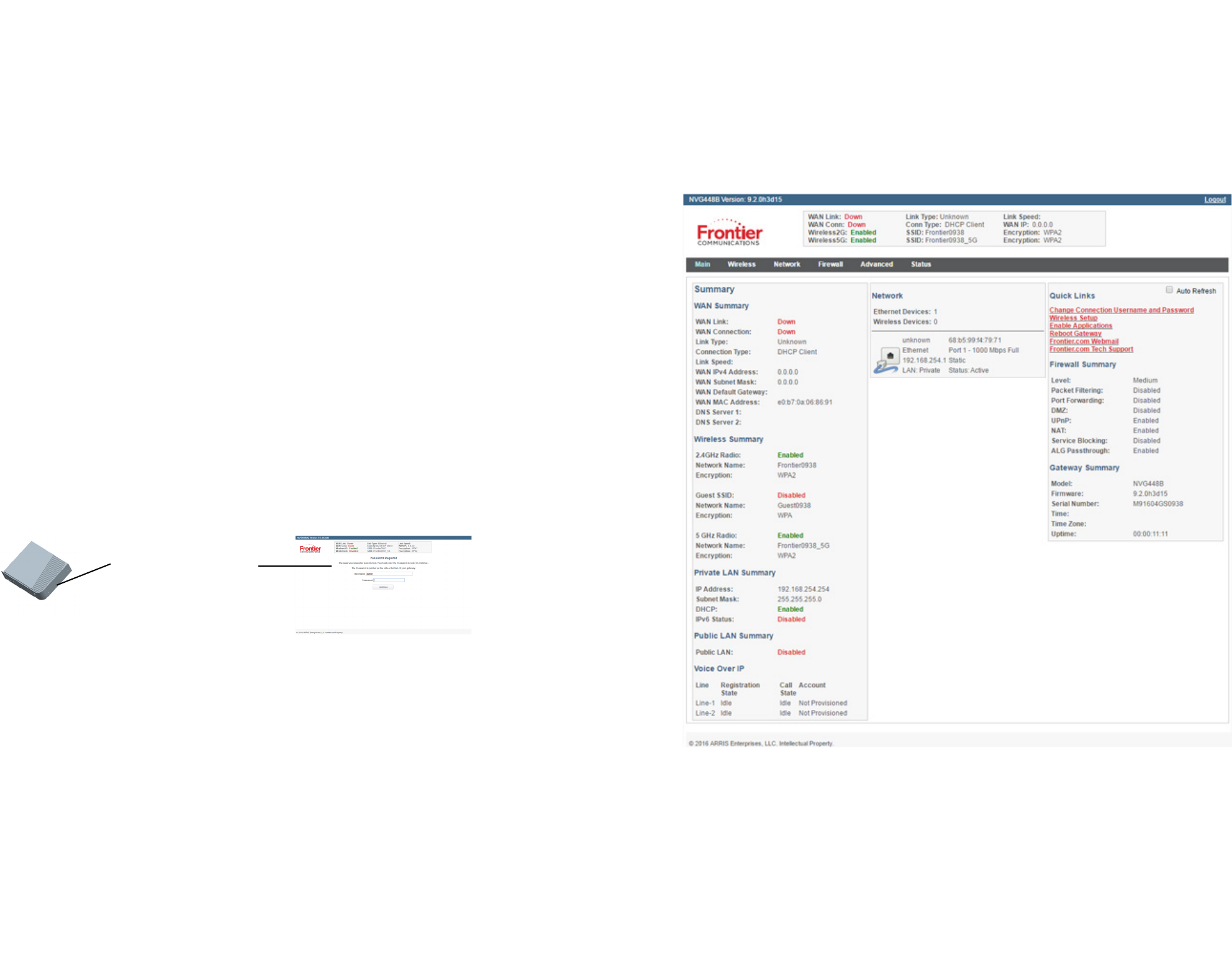
Main Page
The Main page provides an overview of the connection and home network status. From this screen, other detailed status and configuration screens can
be accessed including the following:
• Main — network status/configuration
• Wireless — network status/configuration, including security settings
• Network — status of all devices in the LAN Host Discovery table
• Firewall — status/configuration
• Advanced — advanced settings and configuration, including the Reboot (Factory Reset) options
• Status — system status/configuration
Add a Wireless Device to the Gateway
On the wireless device, use the Wireless setup option to find the available wireless network names. The Wi-Fi Network Name for the gateway is printed
on the bottom label along with the Wi-Fi Password.
NOTE: Optionally, WiFi Protected Setup (WPS) can be used to allow wireless devices with WPS support to join by pressing the WPS button on the front
panel and following the wireless device instructions provided. The WiFi Configure screen provides access to enable or disable the WPS, and can also be
used to change the default wireless network name and password.
Password
Device Access
Code Location
Required Page
NOTE: The terms Device Access Code and Password are sometimes used interchangeably.
Main Page
Part Number: 599527-001-00
Declaration of Conformance
WARNING: This is a Class B product. In a domestic environment this product may cause radio interference, in which case the user may be required to take adequate
measures. Adequate measures include increasing the physical distance between this product and other electrical devices. Changes or modifications to this unit not
expressly approved by the party responsible for compliance could void the user’s authority to operate the equipment.
United States: This device complies with Part 15 of the FCC Rules. Operation is subject to the following two conditions:
1. This device may not cause harmful interference, and
2. This device must accept any interference received, including interference that may cause undesired operation.
This equipment has been tested and found to comply with the limits for a Class B digital device, pursuant to Part 15 of the FCC Rules. These limits are designed to provide
reasonable protection against harmful interference in a residential installation. This equipment generates, uses, and can radiate radio frequency energy and, if not
installed and used in accordance with the instructions, may cause harmful interference to radio communications. However, there is no guarantee that interference will
not occur in a particular installation. If this equipment does cause harmful interference to radio or television reception, which can be determined by turning the
equipment off and on, the user is encouraged to try to correct the interference by one or more of the following measures:
• Reorient or relocate the device.
• Increase the distance between the equipment being interfered with and the device.
• Connect the device to an outlet on a circuit different from the outlet to which the equipment being interfered with is connected.
• Consult the retailer or an experienced radio/TV technician for help.
United States: This device complies with 47 CFR Part 68 of the FCC Rules. Operation is subject to the following four conditions:
1. The Federal Communications Commission (FCC) has established Rules which permit this device to be directly connected to the telephone network. Standardized
jacks are used for these connections. This equipment should not be used on party lines or coin phones.
2. If this device is malfunctioning, it may also be causing harm to the telephone network; this device should be disconnected until the source of the problem can be
determined and until repair has been made. If this is not done, the telephone company may temporarily disconnect service.
3. The telephone company may make changes in its technical operations and procedures; if such changes affect the compatibility or use of this device, the telephone
company is required to give adequate notice of the changes. You will be advised of your right to file a complaint with the FCC.
4. If the telephone company requests information on what equipment is connected to their lines, inform them of:
• The telephone number to which this unit is connected.
• The ringer equivalence number. [0.XB] (Indicated on the label)
• The USOC jack required. [RJ11C]
• The FCC Registration Number. [XXXUSA-XXXXX-XX-E] (Indicated on the label)
The Ringer Equivalence Number (REN) is used to determine how many devices can be connected to your telephone line. In most areas, the sum of the REN's of all
devices on any one line should not exceed five (5.0). If too many devices are attached, they may not ring properly.
FCC Caution: Any changes or modifications not expressly approved by the party responsible for compliance could void the user’s authority to operate this equipment.
This transmitter must not be co-located or operating in conjunction with any other antenna or transmitter. Operations within the 5.15 ~ 5.25 GHz band are restricted to
indoor use only.
Radiation Exposure Statement: This equipment complies with FCC radiation exposure limits as set forth for an uncontrolled environment. This equipment should be
installed and operated maintaining a minimum distance of 27 cm between the device and your body.
Service Requirements: In the event of equipment malfunction, if under warranty, we will exchange a product deemed defective. Under FCC rules, no customer is
authorized to repair this equipment. This restriction applies regardless of whether the equipment is in or out of warranty.
Technical Support for Hardware Products:
Customers inside North America: 888-944-4357 (888-944-HELP)
Customers outside North America: 1-215-323-2345
For Spanish language support: 1-215-323-2346
All ARRIS products are furnished under a license agreement included with the product. If you are unable to locate a copy of the license agreement, please contact ARRIS.
IMPORTANT: This product was tested for FCC compliance under conditions that included the use of shielded cables and connectors between system components.
Changes or modifications to this product not authorized by the manufacturer could void your authority to operate the equipment.
Copyright
©ARRIS Enterprises, LLC, 2016 All rights reserved. No part of this publication may be reproduced in any form or by any means or used to make any derivative work (such
as translation, transformation, or adaptation) without written permission from ARRIS Enterprises, Inc. (“ARRIS”). ARRIS reserves the right to revise this publication and to
make changes in content from time to time without obligation on the part of ARRIS to provide notification of such revision or change.
ARRIS and the ARRIS logo are all trademarks of ARRIS Enterprises, Inc. Other trademarks and trade names may be used in this document to refer to either the entities
claiming the marks and the names of their products. ARRIS disclaims proprietary interest in the marks and names of others.
ARRIS provides this guide without warranty of any kind, implied or expressed, including, but not limited to, the implied warranties of merchantability and fitness for a
particular purpose. ARRIS may make improvements or changes in the product(s) described in this manual at any time.
The capabilities, system requirements and/or compatibility with third-party products described herein are subject to change without notice.
EXCEPT AS INDICATED IN THE APPLICABLE SYSTEM PURCHASE AGREEMENT, THE SYSTEM, DOCUMENTATION AND SERVICES ARE PROVIDED “AS IS”, AS AVAILABLE,
WITHOUT WARRANTY OF ANY KIND. ARRIS GROUP, INC. (“ARRIS”) DOES NOT WARRANT THAT THE SYSTEM WILL MEET CUSTOMER'S REQUIREMENTS, OR THAT THEIR
OPERATION WILL BE UNINTERRUPTED OR ERROR-FREE, OR THAT ANY ERRORS CAN OR WILL BE FIXED. ARRIS HEREBY DISCLAIMS ALL OTHER WARRANTIES, EXPRESS OR
IMPLIED, ORAL OR WRITTEN, WITH RESPECT TO THE SYSTEM AND SERVICES INCLUDING, WITHOUT LIMITATION, ALL IMPLIED WARRANTIES OF TITLE, NON-
INFRINGEMENT, INTEGRATION, MERCHANTABILITY OR FITNESS FOR ANY PARTICULAR PURPOSE AND ALL WARRANTIES ARISING FROM ANY COURSE OF DEALING OR
PERFORMANCE OR USAGE OF TRADE. EXCEPT AS INDICATED IN THE APPLICABLE SYSTEM PURCHASE AGREEMENT, ARRIS SHALL NOT BE LIABLE CONCERNING THE
SYSTEM OR SUBJECT MATTER OF THIS DOCUMENTATION, REGARDLESS OF THE FORM OF ANY CLAIM OR ACTION (WHETHER IN CONTRACT, NEGLIGENCE, STRICT
LIABILITY OR OTHERWISE), FOR ANY (A) MATTER BEYOND ITS REASONABLE CONTROL, (B) LOSS OR INACCURACY OF DATA, LOSS OR INTERRUPTION OF USE, OR COST OF
PROCURING SUBSTITUTE TECHNOLOGY, GOODS OR SERVICES, (C) INDIRECT, PUNITIVE, INCIDENTAL, RELIANCE, SPECIAL, EXEMPLARY OR CONSEQUENTIAL DAMAGES
INCLUDING, BUT NOT LIMITED TO, LOSS OF BUSINESS, REVENUES, PROFITS OR GOODWILL, OR (D) DIRECT DAMAGES, IN THE AGGREGATE, IN EXCESS OF THE FEES PAID
TO IT HEREUNDER FOR THE SYSTEM OR SERVICE GIVING RISE TO SUCH DAMAGES DURING THE 12-MONTH PERIOD PRIOR TO THE DATE THE CAUSE OF ACTION AROSE,
EVEN IF COMPANY HAS BEEN ADVISED OF THE POSSIBILITY OF SUCH DAMAGES. THESE LIMITATIONS ARE INDEPENDENT FROM ALL OTHER PROVISIONS OF THIS
AGREEMENT AND SHALL APPLY NOTWITHSTANDING THE FAILURE OF ANY REMEDY PROVIDED HEREIN.
NVG468MQ Ethernet and FTTH Gateway Quick Start Guide
Introduction
Use this Quick Start Guide to install, configure, and perform basic troubleshooting for the ARRIS™ NVG468MQ Ethernet and FTTH Gateway.
Power Supply Installation
Connect the power supply cord to the power connection on the gateway. Plug the power supply into an appropriate electrical outlet.
WARNING: The power supply must be connected to an outlet with a protective earth connection. Do not defeat the protective earth connection.
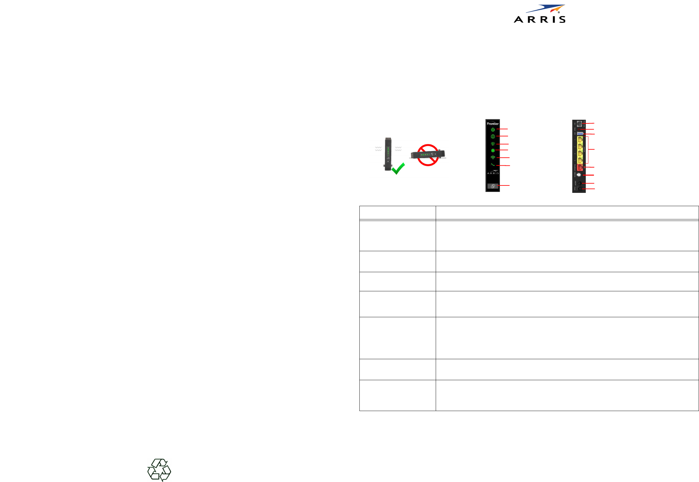
Product Ventilation
The gateway is intended for residential use. Position the gateway in an upright vertical position and locate it where temperatures remain within a range
of 32° – 104°F (0° – 40°C) and where heat from the unit itself is not trapped, requires at least two inches (2”) of clearance on all sides except bottom.
Gateway Positioning, Status Indicator Lights and Port Configuration
Proper positioning of the gateway is essential for proper cooling. Colored LEDs on the gateway indicate the status of various port activity.
LED Status
Power
Solid Green = The device is powered.
Flashing Green = The device is booting.
Solid Red = Boot failure.
Flashing Red = Detecting Factory Reset (press and hold the recessed Reset Switch for 1 second to reboot the device and for 10 or
more seconds to trigger the factory reset).
Internet
Solid Blue = Broadband Internet connection is active.
Solid Red = No IP address or authentication failed.
Off = No active Broadband connection.
Broadband Solid Green = Ethernet WAN connection is active.
Solid Red = No Broadband Ethernet WAN signal on the line.
MoCA LAN
Solid Green = MoCA LAN connection is active.
Flashing Green = MoCA LAN is detecting, connecting and configuring.
Solid Red = No MoCA LAN signal on the line.
Off = MoCA is disabled.
Wi-Fi
Solid Green = Wireless enabled (either radio).
Flashing Yellow = WiFi Protected Setup (WPS) is active.
• Slow flash = less than 3 sec WPS push for 5GHz SSID user pairing. Can be changed to 2.4GHz.
• Fast flash = 3 sec or longer WPS push for 5GHz Video SSID pairing.
Flashing Red = WPS timeout or conflict.
Solid Red = Wireless network failure.
Off = Wireless disabled (both radios).
LAN/WAN Ethernet
LEDs on rear panel RJ45 ports
Solid Green = Port is active.
Flashing Green = Traffic passing on the line.
Off = Port not active.
Phone Line
Solid Green = All VoIP voice lines are registered and active.
Flashing Green = A voice line is ringing or off-hook.
Solid Yellow = Both lines of a two line system are provisionedwith one unregistered.
Solid Red = All provisioned VoIP voice lines are provisioned but but not SIP registered.
Off = VoIP is not provisioned, or the gateway power is off.
Power
Wi-Fi
Broadband
Power Connection
Power Button
ONT Broadband Port
LAN Ethernet Ports With LED Support
USB Port
Phone Jack
Phone
Reset Switch (recessed)
Do Not Position
Horizontally
5cm/2”
Minimum Spacing
5cm/2”
Internet
MoCA
WPS
MoCA Cable Connector