ARRIS Group NVG599 DSL User Manual 3341 User Guide
ARRIS Group, Inc. DSL 3341 User Guide
Contents
- 1. User Manual.pdf
- 2. User Manual Part 1
- 3. User Manual Part 2
User Manual Part 1
ARRIS® NVG599 VDSL2 Gateway
ARRIS
®
Embedded Software Version 9.1.4h0d51
Administrator’s Handbook

Administrator’s Handbook
Copyright
©ARRIS Enterprises, Inc. 2014 All rights reserved. No part of this publication may be reproduced in any form or by any means or
used to make any derivative work (such as translation, transformation, or adaptation) without written permission from ARRIS
Enterprises, Inc. (“ARRIS”). ARRIS reserves the right to revise this publication and to make changes in content from time to time
without obligation on the part of ARRIS to provide notification of such revision or change.
ARRIS and the ARRIS logo are all trademarks of ARRIS Enterprises, Inc. Other trademarks and trade names may be used in this
document to refer to either the entities claiming the marks and the names of their products. ARRIS disclaims proprietary interest in
the marks and names of others. MOTOROLA and the Stylized M logo are trademarks or registered trademarks of Motorola
Trademark Holdings, LLC. and are used by ARRIS under license. All other product or service names are the property of their
respective owners.
ARRIS provides this guide without warranty of any kind, implied or expressed, including, but not limited to, the implied warranties of
merchantability and fitness for a particular purpose. ARRIS may make improvements or changes in the product(s) described in this
manual at any time.
The capabilities, system requirements and/or compatibility with third-party products described herein are subject to change without
notice.
EXCEPT AS INDICATED IN THE APPLICABLE SYSTEM PURCHASE AGREEMENT, THE SYSTEM, DOCUMENTATION AND
SERVICES ARE PROVIDED "AS IS", AS AVAILABLE, WITHOUT WARRANTY OF ANY KIND. ARRIS GROUP, INC. (“ARRIS”)
DOES NOT WARRANT THAT THE SYSTEM WILL MEET CUSTOMER'S REQUIREMENTS, OR THAT THEIR OPERATION WILL
BE UNINTERRUPTED OR ERROR-FREE, OR THAT ANY ERRORS CAN OR WILL BE FIXED. ARRIS HEREBY DISCLAIMS ALL
OTHER WARRANTIES, EXPRESS OR IMPLIED, ORAL OR WRITTEN, WITH RESPECT TO THE SYSTEM AND SERVICES
INCLUDING, WITHOUT LIMITATION, ALL IMPLIED WARRANTIES OF TITLE, NON-INFRINGEMENT, INTEGRATION,
MERCHANTABILITY OR FITNESS FOR ANY PARTICULAR PURPOSE AND ALL WARRANTIES ARISING FROM ANY COURSE
OF DEALING OR PERFORMANCE OR USAGE OF TRADE.
EXCEPT AS INDICATED IN THE APPLICABLE SYSTEM PURCHASE AGREEMENT, ARRIS SHALL NOT BE LIABLE
CONCERNING THE SYSTEM OR SUBJECT MATTER OF THIS DOCUMENTATION, REGARDLESS OF THE FORM OF ANY
CLAIM OR ACTION (WHETHER IN CONTRACT, NEGLIGENCE, STRICT LIABILITY OR OTHERWISE), FOR ANY (A) MATTER
BEYOND ITS REASONABLE CONTROL, (B) LOSS OR INACCURACY OF DATA, LOSS OR INTERRUPTION OF USE, OR
COST OF PROCURING SUBSTITUTE TECHNOLOGY, GOODS OR SERVICES, (C) INDIRECT, PUNITIVE, INCIDENTAL,
RELIANCE, SPECIAL, EXEMPLARY OR CONSEQUENTIAL DAMAGES INCLUDING, BUT NOT LIMITED TO, LOSS OF
BUSINESS, REVENUES, PROFITS OR GOODWILL, OR (D) DIRECT DAMAGES, IN THE AGGREGATE, IN EXCESS OF THE
FEES PAID TO IT HEREUNDER FOR THE SYSTEM OR SERVICE GIVING RISE TO SUCH DAMAGES DURING THE 12-
MONTH PERIOD PRIOR TO THE DATE THE CAUSE OF ACTION AROSE, EVEN IF COMPANY HAS BEEN ADVISED OF THE
POSSIBILITY OF SUCH DAMAGES. THESE LIMITATIONS ARE INDEPENDENT FROM ALL OTHER PROVISIONS OF THIS
AGREEMENT AND SHALL APPLY NOTWITHSTANDING THE FAILURE OF ANY REMEDY PROVIDED HEREIN.
All ARRIS products are furnished under a license agreement included with the product. If you are unable to locate a copy of the
license agreement, please contact ARRIS.
Part Number
596491-001-00
V9.1.4h0d51

Table of Contents
CHAPTER 1 - Introduction . . . . . . . . . . . . . . . . . . . . . . . . . . . . . . . . . . . . . 7
About ARRIS Documentation . . . . . . . . . . . . . . . . . . . . . . . . . . . . . . . . 7
Related Documentation . . . . . . . . . . . . . . . . . . . . . . . . . . . . . . . . . . . . 7
Documentation Conventions . . . . . . . . . . . . . . . . . . . . . . . . . . . . . . . . . 8
General. . . . . . . . . . . . . . . . . . . . . . . . . . . . . . . . . . . . . . . . . . . . . . . . . . . . . . . . . . . 8
Internal Web Interface . . . . . . . . . . . . . . . . . . . . . . . . . . . . . . . . . . . . . . . . . . . . . . 8
Command Line Interface. . . . . . . . . . . . . . . . . . . . . . . . . . . . . . . . . . . . . . . . . . . . . 8
Organization . . . . . . . . . . . . . . . . . . . . . . . . . . . . . . . . . . . . . . . . . . . . . 9
A Word About Example Screens . . . . . . . . . . . . . . . . . . . . . . . . . . . . . . 9
CHAPTER 2 - Device Configuration. . . . . . . . . . . . . . . . . . . . . . . . . . . . . 11
Important Safety Instructions . . . . . . . . . . . . . . . . . . . . . . . . . . . . . . . 12
POWER SUPPLY INSTALLATION . . . . . . . . . . . . . . . . . . . . . . . . . . . . . . . . . . . . . . . 12
TELECOMMUNICATION INSTALLATION . . . . . . . . . . . . . . . . . . . . . . . . . . . . . . . . 12
COAX INSTALLATION . . . . . . . . . . . . . . . . . . . . . . . . . . . . . . . . . . . . . . . . . . . . . . . 12
PRODUCT VENTILATION . . . . . . . . . . . . . . . . . . . . . . . . . . . . . . . . . . . . . . . . . . . . 12
Status Indicator Lights . . . . . . . . . . . . . . . . . . . . . . . . . . . . . . . . . . . . . 13
Battery Installation (optional) . . . . . . . . . . . . . . . . . . . . . . . . . . . . . . . 16
Battery Door Instructions . . . . . . . . . . . . . . . . . . . . . . . . . . . . . . . . . . 17
Set up the ARRIS Gateway . . . . . . . . . . . . . . . . . . . . . . . . . . . . . . . . . . 18
Microsoft Windows: . . . . . . . . . . . . . . . . . . . . . . . . . . . . . . . . . . . . . . . . . . . . . . .18
Macintosh MacOS 8 or higher or Mac OS X: . . . . . . . . . . . . . . . . . . . . . . . . . . . . 20
Accessing the Web Management Interface . . . . . . . . . . . . . . . . . . . . 21
Broadband Network Redirect Pages . . . . . . . . . . . . . . . . . . . . . . . . . . . . . . . . . . 22
IP Diagnostics Page Redirect. . . . . . . . . . . . . . . . . . . . . . . . . . . . . . . . . . . . . . . . . 23
Offline Troubleshooting . . . . . . . . . . . . . . . . . . . . . . . . . . . . . . . . . . . . . . . . . . . . 23
Device Status Page . . . . . . . . . . . . . . . . . . . . . . . . . . . . . . . . . . . . . . . 24
Device Access Code. . . . . . . . . . . . . . . . . . . . . . . . . . . . . . . . . . . . . . . . . . . . . . . .24
Tab Bar . . . . . . . . . . . . . . . . . . . . . . . . . . . . . . . . . . . . . . . . . . . . . . . . . 27
Help . . . . . . . . . . . . . . . . . . . . . . . . . . . . . . . . . . . . . . . . . . . . . . . . . . . 27
Links Bar . . . . . . . . . . . . . . . . . . . . . . . . . . . . . . . . . . . . . . . . . . . . . . . 27
Device List . . . . . . . . . . . . . . . . . . . . . . . . . . . . . . . . . . . . . . . . . . . . . . . . 28
System Information . . . . . . . . . . . . . . . . . . . . . . . . . . . . . . . . . . . . . . . . . 29
Access Code . . . . . . . . . . . . . . . . . . . . . . . . . . . . . . . . . . . . . . . . . . . . . . . 30
Remote Access . . . . . . . . . . . . . . . . . . . . . . . . . . . . . . . . . . . . . . . . . . . . . 31
Battery . . . . . . . . . . . . . . . . . . . . . . . . . . . . . . . . . . . . . . . . . . . . . . . . . . . 32
Restart Device . . . . . . . . . . . . . . . . . . . . . . . . . . . . . . . . . . . . . . . . . . . . . 33
Broadband Tab . . . . . . . . . . . . . . . . . . . . . . . . . . . . . . . . . . . . . . . . . . 34
Broadband Status . . . . . . . . . . . . . . . . . . . . . . . . . . . . . . . . . . . . . . . . . . 34
Configure . . . . . . . . . . . . . . . . . . . . . . . . . . . . . . . . . . . . . . . . . . . . . . . . . 37
IGMP Stats . . . . . . . . . . . . . . . . . . . . . . . . . . . . . . . . . . . . . . . . . . . . . . . . 38

Administrator’s Handbook
Home Network Tab . . . . . . . . . . . . . . . . . . . . . . . . . . . . . . . . . . . . . . . .39
Configure . . . . . . . . . . . . . . . . . . . . . . . . . . . . . . . . . . . . . . . . . . . . . . . . . 42
HPNA Configure . . . . . . . . . . . . . . . . . . . . . . . . . . . . . . . . . . . . . . . . . . . . 42
WiFi . . . . . . . . . . . . . . . . . . . . . . . . . . . . . . . . . . . . . . . . . . . . . . . . . . . . . . 43
Wireless Security. . . . . . . . . . . . . . . . . . . . . . . . . . . . . . . . . . . . . . . . . . . . . . . . . . 45
MAC Filtering . . . . . . . . . . . . . . . . . . . . . . . . . . . . . . . . . . . . . . . . . . . . . . 47
WiFi Scan . . . . . . . . . . . . . . . . . . . . . . . . . . . . . . . . . . . . . . . . . . . . . . . . . 48
Subnets & DHCP . . . . . . . . . . . . . . . . . . . . . . . . . . . . . . . . . . . . . . . . . . . . 49
IP Allocation . . . . . . . . . . . . . . . . . . . . . . . . . . . . . . . . . . . . . . . . . . . . . . . 50
HPNA . . . . . . . . . . . . . . . . . . . . . . . . . . . . . . . . . . . . . . . . . . . . . . . . . . . . . 52
Voice . . . . . . . . . . . . . . . . . . . . . . . . . . . . . . . . . . . . . . . . . . . . . . . . . . .54
Line Details . . . . . . . . . . . . . . . . . . . . . . . . . . . . . . . . . . . . . . . . . . . . . . . . 55
Call Statistics . . . . . . . . . . . . . . . . . . . . . . . . . . . . . . . . . . . . . . . . . . . . . . . 56
Firewall . . . . . . . . . . . . . . . . . . . . . . . . . . . . . . . . . . . . . . . . . . . . . . . . .59
Packet Filter . . . . . . . . . . . . . . . . . . . . . . . . . . . . . . . . . . . . . . . . . . . . . . . 60
Working with Packet Filters . . . . . . . . . . . . . . . . . . . . . . . . . . . . . . . . . . . . . . . . . 62
NAT/Gaming . . . . . . . . . . . . . . . . . . . . . . . . . . . . . . . . . . . . . . . . . . . . . . . 67
Custom Services . . . . . . . . . . . . . . . . . . . . . . . . . . . . . . . . . . . . . . . . . . . . . . . . . . 68
IP Passthrough . . . . . . . . . . . . . . . . . . . . . . . . . . . . . . . . . . . . . . . . . . . . . 72
Firewall Advanced . . . . . . . . . . . . . . . . . . . . . . . . . . . . . . . . . . . . . . . . . . 75
Diagnostics . . . . . . . . . . . . . . . . . . . . . . . . . . . . . . . . . . . . . . . . . . . . . .77
Logs . . . . . . . . . . . . . . . . . . . . . . . . . . . . . . . . . . . . . . . . . . . . . . . . . . . . . . 80
Update . . . . . . . . . . . . . . . . . . . . . . . . . . . . . . . . . . . . . . . . . . . . . . . . . . . 82
Resets . . . . . . . . . . . . . . . . . . . . . . . . . . . . . . . . . . . . . . . . . . . . . . . . . . . . 83
Syslog . . . . . . . . . . . . . . . . . . . . . . . . . . . . . . . . . . . . . . . . . . . . . . . . . . . . 84
Event Notifications . . . . . . . . . . . . . . . . . . . . . . . . . . . . . . . . . . . . . . . . . . 84
NAT Table . . . . . . . . . . . . . . . . . . . . . . . . . . . . . . . . . . . . . . . . . . . . . . . . . 85
CHAPTER 3 - Basic Troubleshooting . . . . . . . . . . . . . . . . . . . . . . . . . . . . 87
Status Indicator Lights . . . . . . . . . . . . . . . . . . . . . . . . . . . . . . . . . . . . .88
LED Function Summary Matrix. . . . . . . . . . . . . . . . . . . . . . . . . . . . . . . . . . . . . . . 91
Factory Reset Switch . . . . . . . . . . . . . . . . . . . . . . . . . . . . . . . . . . . . . .95
Log Event Messages . . . . . . . . . . . . . . . . . . . . . . . . . . . . . . . . . . . . . . .96
CHAPTER 4 - Command Line Interface . . . . . . . . . . . . . . . . . . . . . . . . . 101
Overview . . . . . . . . . . . . . . . . . . . . . . . . . . . . . . . . . . . . . . . . . . . . . .103
Starting and Ending a CLI Session . . . . . . . . . . . . . . . . . . . . . . . . . . . .105
Logging In. . . . . . . . . . . . . . . . . . . . . . . . . . . . . . . . . . . . . . . . . . . . . . . . . . . . . . . 105
Ending a CLI Session . . . . . . . . . . . . . . . . . . . . . . . . . . . . . . . . . . . . . . . . . . . . . . 105
Using the CLI Help Facility . . . . . . . . . . . . . . . . . . . . . . . . . . . . . . . . .106
About SHELL Commands . . . . . . . . . . . . . . . . . . . . . . . . . . . . . . . . . .106
SHELL Prompt . . . . . . . . . . . . . . . . . . . . . . . . . . . . . . . . . . . . . . . . . . . . . . . . . . . 106
SHELL Command Shortcuts. . . . . . . . . . . . . . . . . . . . . . . . . . . . . . . . . . . . . . . . . 106
SHELL Commands . . . . . . . . . . . . . . . . . . . . . . . . . . . . . . . . . . . . . . . .107
Common Commands. . . . . . . . . . . . . . . . . . . . . . . . . . . . . . . . . . . . . . . . . . . . . . 107
WPS Commands . . . . . . . . . . . . . . . . . . . . . . . . . . . . . . . . . . . . . . . . . . . . . . . . . 116

WAN Commands . . . . . . . . . . . . . . . . . . . . . . . . . . . . . . . . . . . . . . . . . . . . . . . . .116
About CONFIG Commands . . . . . . . . . . . . . . . . . . . . . . . . . . . . . . . . 118
CONFIG Mode Prompt . . . . . . . . . . . . . . . . . . . . . . . . . . . . . . . . . . . . . . . . . . . .118
Navigating the CONFIG Hierarchy . . . . . . . . . . . . . . . . . . . . . . . . . . . . . . . . . . .118
Entering Commands in CONFIG Mode. . . . . . . . . . . . . . . . . . . . . . . . . . . . . . . .118
Guidelines: CONFIG Commands. . . . . . . . . . . . . . . . . . . . . . . . . . . . . . . . . . . . .119
Displaying Current Gateway Settings. . . . . . . . . . . . . . . . . . . . . . . . . . . . . . . . .119
Step Mode: A CLI Configuration Technique. . . . . . . . . . . . . . . . . . . . . . . . . . . .119
Validating Your Configuration. . . . . . . . . . . . . . . . . . . . . . . . . . . . . . . . . . . . . . .120
CONFIG Commands . . . . . . . . . . . . . . . . . . . . . . . . . . . . . . . . . . . . . . 121
Connection Commands. . . . . . . . . . . . . . . . . . . . . . . . . . . . . . . . . . . . . . . . . . . .121
Filter Set Commands. . . . . . . . . . . . . . . . . . . . . . . . . . . . . . . . . . . . . . . . . . . . . .124
Global Filter Set (“IPv6 Firewall”) Commands. . . . . . . . . . . . . . . . . . . . . . . . . .128
Queue Commands. . . . . . . . . . . . . . . . . . . . . . . . . . . . . . . . . . . . . . . . . . . . . . . .129
IP Gateway Commands . . . . . . . . . . . . . . . . . . . . . . . . . . . . . . . . . . . . . . . . . . . .132
IPv6 Commands. . . . . . . . . . . . . . . . . . . . . . . . . . . . . . . . . . . . . . . . . . . . . . . . . .132
IP DNS Commands. . . . . . . . . . . . . . . . . . . . . . . . . . . . . . . . . . . . . . . . . . . . . . . .139
IP IGMP Commands. . . . . . . . . . . . . . . . . . . . . . . . . . . . . . . . . . . . . . . . . . . . . . .139
NTP Commands . . . . . . . . . . . . . . . . . . . . . . . . . . . . . . . . . . . . . . . . . . . . . . . . . .142
Application Layer Gateway (ALG) Commands. . . . . . . . . . . . . . . . . . . . . . . . . .142
Dynamic DNS Commands . . . . . . . . . . . . . . . . . . . . . . . . . . . . . . . . . . . . . . . . . .143
Link Commands . . . . . . . . . . . . . . . . . . . . . . . . . . . . . . . . . . . . . . . . . . . . . . . . . .143
Management Commands . . . . . . . . . . . . . . . . . . . . . . . . . . . . . . . . . . . . . . . . . .146
Remote Access Commands. . . . . . . . . . . . . . . . . . . . . . . . . . . . . . . . . . . . . . . . .148
Physical Interfaces Commands. . . . . . . . . . . . . . . . . . . . . . . . . . . . . . . . . . . . . .150
PPPoE Relay Commands . . . . . . . . . . . . . . . . . . . . . . . . . . . . . . . . . . . . . . . . . . .157
NAT Pinhole Commands . . . . . . . . . . . . . . . . . . . . . . . . . . . . . . . . . . . . . . . . . . .157
Security Stateful Packet Inspection (SPI) Commands . . . . . . . . . . . . . . . . . . . .158
VoIP Commands. . . . . . . . . . . . . . . . . . . . . . . . . . . . . . . . . . . . . . . . . . . . . . . . . .160
Targeted Ad Insertion Commands . . . . . . . . . . . . . . . . . . . . . . . . . . . . . . . . . . .171
System Commands . . . . . . . . . . . . . . . . . . . . . . . . . . . . . . . . . . . . . . . . . . . . . . .173
Debug Commands . . . . . . . . . . . . . . . . . . . . . . . . . . . . . . . . . . . . . . . 178
Disclaimer and Warning Text . . . . . . . . . . . . . . . . . . . . . . . . . . . . . . . . . . . . . . . 178
Commands . . . . . . . . . . . . . . . . . . . . . . . . . . . . . . . . . . . . . . . . . . . . . . . . . . . . . .178
TR-069 CLI CShell Commands (debug mode) . . . . . . . . . . . . . . . . . . . . . . . . . . 178
CHAPTER 5 - Technical Specifications and Safety Information. . . . . . 179
Description . . . . . . . . . . . . . . . . . . . . . . . . . . . . . . . . . . . . . . . . . . . . 179
Power Supply . . . . . . . . . . . . . . . . . . . . . . . . . . . . . . . . . . . . . . . . . . . . . . . . . . . .179
Environment. . . . . . . . . . . . . . . . . . . . . . . . . . . . . . . . . . . . . . . . . . . . . . . . . . . . .179
Software and protocols. . . . . . . . . . . . . . . . . . . . . . . . . . . . . . . . . . . . . . . . . . . .179
Agency approvals . . . . . . . . . . . . . . . . . . . . . . . . . . . . . . . . . . . . . . . 180
Manufacturer’s Declaration of Conformance . . . . . . . . . . . . . . . . . . 181
Important Safety Instructions . . . . . . . . . . . . . . . . . . . . . . . . . . . . . . 183
47 CFR Part 68 Information . . . . . . . . . . . . . . . . . . . . . . . . . . . . . . . . 184
FCC Requirements . . . . . . . . . . . . . . . . . . . . . . . . . . . . . . . . . . . . . . . . . . . . . . . .184
FCC Statements . . . . . . . . . . . . . . . . . . . . . . . . . . . . . . . . . . . . . . . . . . . . . . . . . .184
RF Exposure Statement: . . . . . . . . . . . . . . . . . . . . . . . . . . . . . . . . . . 185

Administrator’s Handbook
Electrical Safety Advisory . . . . . . . . . . . . . . . . . . . . . . . . . . . . . . . . . .185
Caring for the Environment by Recycling . . . . . . . . . . . . . . . . . . . . . .186
Beskyttelse af miljøet med genbrug . . . . . . . . . . . . . . . . . . . . . . . . . . . . . . . . . 186
Umweltschutz durch Recycling. . . . . . . . . . . . . . . . . . . . . . . . . . . . . . . . . . . . . . 186
Cuidar el medio ambiente mediante el reciclaje . . . . . . . . . . . . . . . . . . . . . . . 186
Recyclage pour le respect de l'environnement. . . . . . . . . . . . . . . . . . . . . . . . . 186
Milieubewust recycleren . . . . . . . . . . . . . . . . . . . . . . . . . . . . . . . . . . . . . . . . . . 187
Dba³oÊç o Êrodowisko - recykling . . . . . . . . . . . . . . . . . . . . . . . . . . . . . . . . . . . 187
Cuidando do meio ambiente através da reciclagem . . . . . . . . . . . . . . . . . . . . 187
Var rädd om miljön genom återvinning. . . . . . . . . . . . . . . . . . . . . . . . . . . . . . . 187
Copyright Acknowledgments . . . . . . . . . . . . . . . . . . . . . . . . . . . . . . .189
Open Source Software Information . . . . . . . . . . . . . . . . . . . . . . . . . . . . . . . . . . 189
Appendix A - ARRIS Gateway Captive Portal Implementation . . . . . . 213
Overview . . . . . . . . . . . . . . . . . . . . . . . . . . . . . . . . . . . . . . . . . . . . . .214
Captive Portal RPC . . . . . . . . . . . . . . . . . . . . . . . . . . . . . . . . . . . . . . .215
X_00D09E_GetCaptivePortalParams RPC:. . . . . . . . . . . . . . . . . . . . . . . . . . . . . 215
X_00D09E_SetCaptivePortalParams RPC: . . . . . . . . . . . . . . . . . . . . . . . . . . . . . 216
Appendix B - Quality of Service (QoS) Examples . . . . . . . . . . . . . . . . . 217
Overview . . . . . . . . . . . . . . . . . . . . . . . . . . . . . . . . . . . . . . . . . . . . . .218
Upstream QoS: Priority and Shaping . . . . . . . . . . . . . . . . . . . . . . . . .220
Downstream QoS: Ethernet Switch . . . . . . . . . . . . . . . . . . . . . . . . . .221
Downstream QoS: Egress queues . . . . . . . . . . . . . . . . . . . . . . . . . . . .221
Index . . . . . . . . . . . . . . . . . . . . . . . . . . . . . . . . . . . . . . . . . . . . . . . . . . . 223

7
CHAPTER 1 Introduction
About ARRIS Documentation
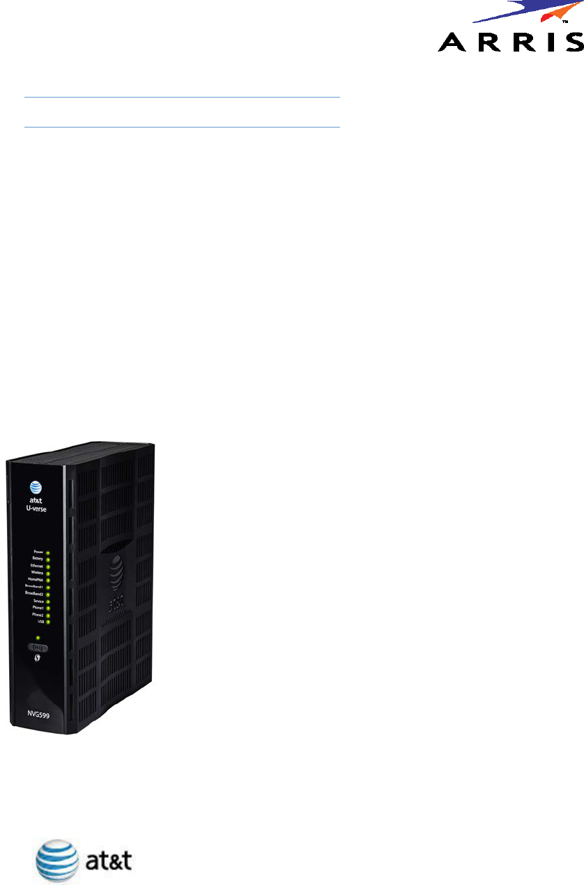
This guide describes the wide variety of features and functionality of the ARRIS NVG599 Gateway, when used in Router
mode. The NVG599 device can also be delivered in Bridge mode. In Bridge mode, the NVG599 acts as a pass-through device
and allows the workstations on your LAN to have public addresses directly on the Internet. Documentation for the NVG599
in Bridge mode is available for download.
Related Documentation
ARRIS provides a suite of technical documents for its family of intelligent enterprise and consumer gateways.
This documentation consists of:
Administrator’s Handbook (this document)
Dedicated user manuals
Specific white papers covering related technology
The documents are available in electronic form as Portable Document Format (PDF) files. They can be viewed
(and printed) from Adobe Acrobat Reader, Exchange, or any other application that supports PDF files.
NOTE::
For the purposes of this manual the “ARRIS NVG599 Gateway” will be referred to as the “NVG599.”

Administrator’s Handbook
8
Documentation Conventions
This manual uses the following conventions to present information.
General
The following typographic conventions are used in this guide.
Internal Web Interface
The following graphic conventions are used when describing elements of the Web interface in this guide.
Command Line Interface
Syntax conventions for the command line interface are as follows.
Convention Description
bold sans serif Menu commands and button names
underlined sans serif Web GUI page links
terminal Computer display text
bold terminal User-entered text
Italic The complete titles of manuals
Convention (Graphics) Description
An excerpt from a Web page or the visual truncation of a Web page
An area of emphasis on a Web page
Convention Description
[ ] Optional command arguments are shown with straight brackets
{ } Alternative values for an argument are presented in curly ({ }) brack-
ets, with values separated by vertical bars (|).
bold User-entered text
italic Variables for which you supply your own values
blue border
solid rounded rectangle
with an arrow

9
Organization
This guide consists of five chapters, two appendixes, and an index. It is organized as follows:
Chapter 1, “Introduction” — Describes the ARRIS® document suite and the purpose of, audience for, and
structure of this guide. It includes a table of style conventions.
Chapter 2, “Device Configuration” — Describes how to get up and running with your NVG599.
Chapter 3, “Basic Troubleshooting” — Gives some simple suggestions for troubleshooting problems with
the initial configuration of your NVG599.
Chapter 4, “Command Line Interface” — Describes all the current text-based commands for both the SHELL
and CONFIG modes. A summary table and individual command examples for each mode are provided.
Chapter 5, “Technical Specifications and Safety Information” — Presents system and device specifications
and important compliance and safety statements.
Appendix A, "ARRIS Gateway Captive Portal Implementation" — Describes the ARRIS Gateway Captive Por-
tal Implementation.
Appendix B, "Quality of Service (QoS) Examples" — Describes the ARRIS Gateway Quality of Service (QoS)
Implementation.
A Word About Example Screens
This manual contains many example screen illustrations. Since ARRIS gateways offer a wide variety of features
and functionality, the example screens shown may not exactly match the screens for your particular device or
setup. The example screens are for illustrative and explanatory purposes, and should not be construed to
represent your own unique environment.

Administrator’s Handbook
10

11
CHAPTER 2 Device Configuration
Most users will find that the basic Quick Start configuration is sufficient to meet their needs. The Quick Start
section may be all that you need to configure and use your ARRIS NVG599 Gateway. For more advanced users,
a rich feature set is available. The following instructions cover installation in Router mode.
This chapter covers:
“Important Safety Instructions” on page 12
“Status Indicator Lights” on page 13
“Battery Installation (optional)” on page 16
“Battery Door Instructions” on page 17
“Set up the ARRIS Gateway” on page 18
“Accessing the Web Management Interface” on page 21
“Device Status Page” on page 24
“Tab Bar” on page 27
“Broadband Tab” on page 34
“Home Network Tab” on page 39
“WiFi” on page 43
“Voice” on page 54
“Firewall” on page 59
“Diagnostics” on page 77

Administrator’s Handbook
12
Important Safety Instructions
POWER SUPPLY INSTALLATION
Connect the power supply cord to the power jack on the NVG599. Plug the power supply into an appropriate
electrical outlet. There is no power (on / off) switch to power off the device.
TELECOMMUNICATION INSTALLATION
When using your telephone equipment, basic safety precautions should always be followed to reduce the risk
of fire, electric shock, and injury, including the following:
This device is intended for indoor use only.
Do not use this product near water, for example, near a bathtub, wash bowl, kitchen sink or laundry tub, in a
wet basement or near a swimming pool.
Avoid using a telephone (other than a cordless type) during an electrical storm. There may be a remote risk
of electrical shock from lightning.
Do not use the telephone to report a gas leak in the vicinity of the leak.
CAUTION: The external phone should be UL listed, and the connections should be made in accordance with
Article 800 of the NEC.
CAUTION: To reduce the risk of fire, use only No. 26 AWG or larger telecommunication line cord.
COAX INSTALLATION
Ensure that the outside coaxial cable system is grounded, so as to provide some protection against voltage
surges and built-up static charges. Article 820-20 of the NEC (Section 54, Part I of the Canadian Electrical Code)
provides guidelines for proper grounding and, in particular, specifies that the CATV cable ground be connected
to the grounding system of the building, as close to the point of cable entry as practical.
PRODUCT VENTILATION
The NVG599 is intended for use in a consumer's home. Ambient temperatures should not exceed 104 F
(40 C). The NVG599 should not be used in locaƟons exposed to outside heat radiaƟon or where it is subject to
trapping of its own heat. The product should have at least one inch of clearance on all sides except the bottom
when properly installed and should not be placed inside tightly enclosed spaces unless proper ventilation is
provided.
SAVE THESE INSTRUCTIONS
WARNING:
The power supply must be connected to a mains outlet with a protective earth connection. Do not defeat the
protective earth connection.
CAUTION:
Depending on the power supply provided with the product, either the direct plug-in power supply blades,
power supply cord plug or the appliance coupler serves as the mains power disconnect. It is important that
the direct plug-in power supply, socket-outlet or appliance coupler be located so it is readily accessible.
RESTRICTIONS:
Do not install this device out doors.
This device is restricted from transmitting in 5600-5650 MHz band.
WARNING:
Installing and operating this device out doors is a violation of FCC rules.
WARNING:
The battery used in this device may present a risk of fire or chemical burn if mistreated. Do not disassemble,
heat above manufacturer’s maximum temperature limit, or incinerate. Replace battery with ARRIS
P/N 586185-002-00 only. Use of another battery may present a risk of fire or explosion.
Dispose of used battery promptly. Keep away from children. Do not disassemble and do not dispose of in fire.

13
Status Indicator Lights
Colored LEDs on your NVG599 indicate the activity status of various ports.
ARRIS NVG599 Status Indicator Lights
LED Activity
Power
Solid Green = The device is powered.
Flashing Green = A power-on self-test (POST) is in progress
Flashing Red = A POST failure (not bootable) or device malfunction occurred.
Flashing Amber = Firmware upgrade in progress (see below)
Off = The unit has no AC power. If the battery is in use, the Battery LED will indicate battery status,
and all other LEDs will be off.
Power during
Firmware
Upgrade
During the software installation, you will lose Internet and phone service. The LEDs will function as
follows:
1. As firmware is being loaded into flash, the LEDs operate normally.
2. During the firmware upgrade, which takes a few minutes, the Power LED will flashes amber
(flash writing to memory), and all other LEDs are off.
3. The NVG599 restarts automatically.
As the device reboots, the LEDs display power-on behavior.
All during
Boot process
• Power LED = Flashing Green
• All other LEDs = Off
If the device does not boot and fails its self-test or fails to perform initial load of the bootloader:
• Power LED = Flashing Red
• ALL other LEDs = Off
If the device boots and then detects a failure:
Power LED = Flashing Green starting POST, and then all LEDs will flash red, including Power LED.
Battery
Solid Green = Battery in place but not being used.
Flashing Green = Battery charging.
Solid Red = Battery backup mechanism has a fault.
Flashing Red = Battery needs to be replaced.
Solid Amber = Battery in use.
Flashing Amber = Low battery.
Off = No battery, or battery has no charge.
Side View Power
Battery
Ethernet
WiFi
HomePNA
USB
Broadband 1
Broadband 2
Service
Phone 1
Phone 2
WPS

Administrator’s Handbook
14
Ethernet
Solid Green = Powered device connected to the associated port (includes devices with wake-on-LAN
capability where a slight voltage is supplied to the Ethernet connection).
Flickering Green = Activity seen from devices associated with the port. The flickering of the light is
synchronized to actual data traffic.
Off = The device is not powered, or no cable or no powered devices are connected to the associated
ports.
WiFi
Solid Green = Wi-Fi is powered.
Flickering Green = Activity seen from devices connected via Wi-Fi. The flickering of the light is syn-
chronized to actual data traffic.
Off = The device is not powered, or no powered devices are connected to the associated ports.
HomePNA
Solid Green = Powered device connected to the associated port (includes devices with wake-on-LAN
capability where a slight voltage is supplied to the Ethernet connection).
Flickering Green = Activity seen from devices associated with the port. The flickering of the light is
synchronized to actual data traffic.
Off = The device is not powered, or no cable or no powered devices are connected to the associated
ports.
Broadband
1**, 2
Solid Green = Good broadband connection (good DSL sync or Gigabit Ethernet).
Flashing Green = Attempting broadband connection (DSL attempting sync).
Flashing Green and Red = If, after three consecutive minutes, the broadband connection fails to be
established, the LED switches to Flashing Green alternating with a five second steady Red while
attempting or waiting to establish a broadband connection. This pattern continues until the broad-
band connection is successfully established.
Flashing Red = No DSL signal on the line. This display is not used during times of temporary ‘no tone’
during the training sequence.
Off = The device is not powered.
** Broadband 1 LED is also the Gigabit Ethernet WAN LED when that is in play (and DSL is not).
Service
Solid Green = IP connected. The device has a WAN IP address from DHCP or 802.1x authentication
and the broadband connection is up.
Flashing Green = Attempting connection, attempting IEEE 802.1X authentication, or attempting to
obtain DHCP information.
Red = Device attempted to become IP connected and failed (no DHCP response, 802.1x authentica-
tion failed, no IP address from IPCP, etc.). The Red state times out after two minutes, and the Service
indicator light returns to the Off state.
Off = The device is not powered or the broadband connection is not present.
Phone 1, 2
Solid Green = The associated VoIP line has been registered with a SIP proxy server.
Flashing Green = Indicates a telephone is off-hook on the associated VoIP line.
Off = VoIP not in use, line not registered, or gateway power off.
USB
Solid Green = Powered device connected to the associated port (includes devices with wake-on-LAN
capability where a slight voltage is supplied to the Ethernet connection).
Flickering Green = Activity seen from devices associated with the port. The flickering of the light is
synchronized to actual data traffic.
Off = The device is not powered, no cable or no powered devices connected to the associated ports.
LED Activity
15
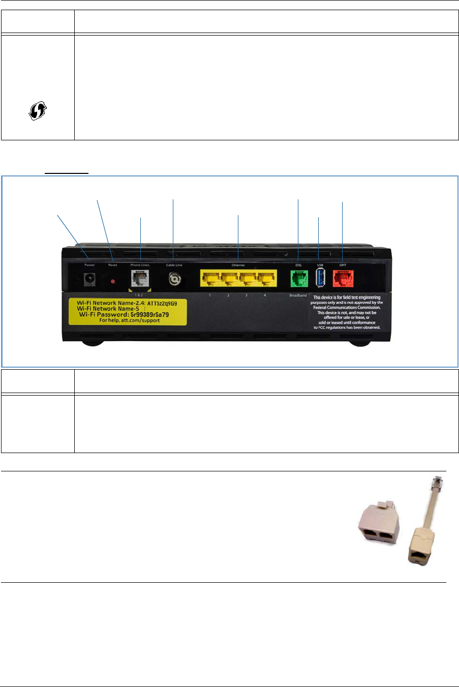
Rear View
WPS
(appears after
using WPS
button)
Solid Green = Wi-Fi Protected Setup has been completed successfully. LED should stay on for 5 min-
utes or until push button is pressed again.
Flashing Green = Continues for 2 minutes, indicating when WPS is broadcasting.
Flashing Red = Continues for 2 minutes, indicating a Session overlap was detected (possible security
risk).
Solid Red = Error unrelated to security, such as failure to find a partner, or WPS is disabled. LED
should stay solid red for 5 minutes or until push button is pressed again.
Off = The device is is ready for WPS authentication.
LED Activity
Ethernet
1, 2, 3, 4
Flashing Amber = A Gigabit Ethernet device is connected to each port.
Solid Green = A 10/100 Ethernet device is connected.
Flickering Green = Ethernet traffic activity.
Off = The device is not powered, or no powered devices are connected to the associated ports.
NOTE:
The NVG599 supports two VoIP lines over one RJ14 (FXS) VoIP port. In order to
connect two phone lines, the supplied inner/outer pair splitter adapters must
be attached to the RJ14 (FXS) VoIP port in order to terminate both lines. This is
a special-purpose splitter. You must use only the inner/outer pair splitter
adapters supplied by AT&T.
LED Activity
Gigabit Ethernet (WAN)
USB
DSL (WAN)
Ethernet (LAN)
F-Connector (HPNA)
RJ14 (FXS)
Reset
Power Jack
Administrator’s Handbook
16
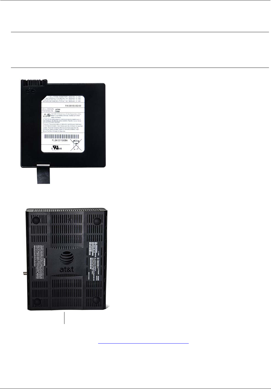
Battery Installation (optional)
The optional backup battery is located in a compartment on the bottom of the unit. Installing the battery door
requires some care.
1. Note the tab on the bottom of the battery.
2. Insert the battery into the compartment on the bottom of the unit, as shown, and press into place so that
the battery contacts seat securely in the unit.
3. Close the compartment door. See “Battery Door Instructions” on page 17.
CAUTION:
The battery used in this device may present a risk of fire or chemical burn if mistreated. Do not disassemble,
heat above manufacturer’s maximum temperature limit, or incinerate. Replace battery with ARRIS P/N
586185-002-00 only. Use of another battery may present a risk of fire or explosion.
Dispose of used battery promptly. Keep away from children. Do not disassemble and do not dispose of in fire.
Battery Compartment Door

17
Battery Door Instructions
1. Place NVG599 unit on a tabletop with the battery door side up.
2. Push in and upward to open the battery door as shown in Figure 1.
3. Swing back the battery door. See Figure 2.
4. Insert the battery in the compartment as shown in Figure 3.
5. Swing the door back down and snap closed.
Figure 1
Figure 2
Figure 3
Administrator’s Handbook
18
Set up the ARRIS Gateway
Refer to your Quick Start Guide for instructions on how to connect your NVG599 to your power source, PC, or
local area network, and your Internet access point, whether it is a dedicated DSL outlet or a DSL or cable
modem. Be sure to enable dynamic addressing on your PC. To set up the gateway, complete the following
steps:
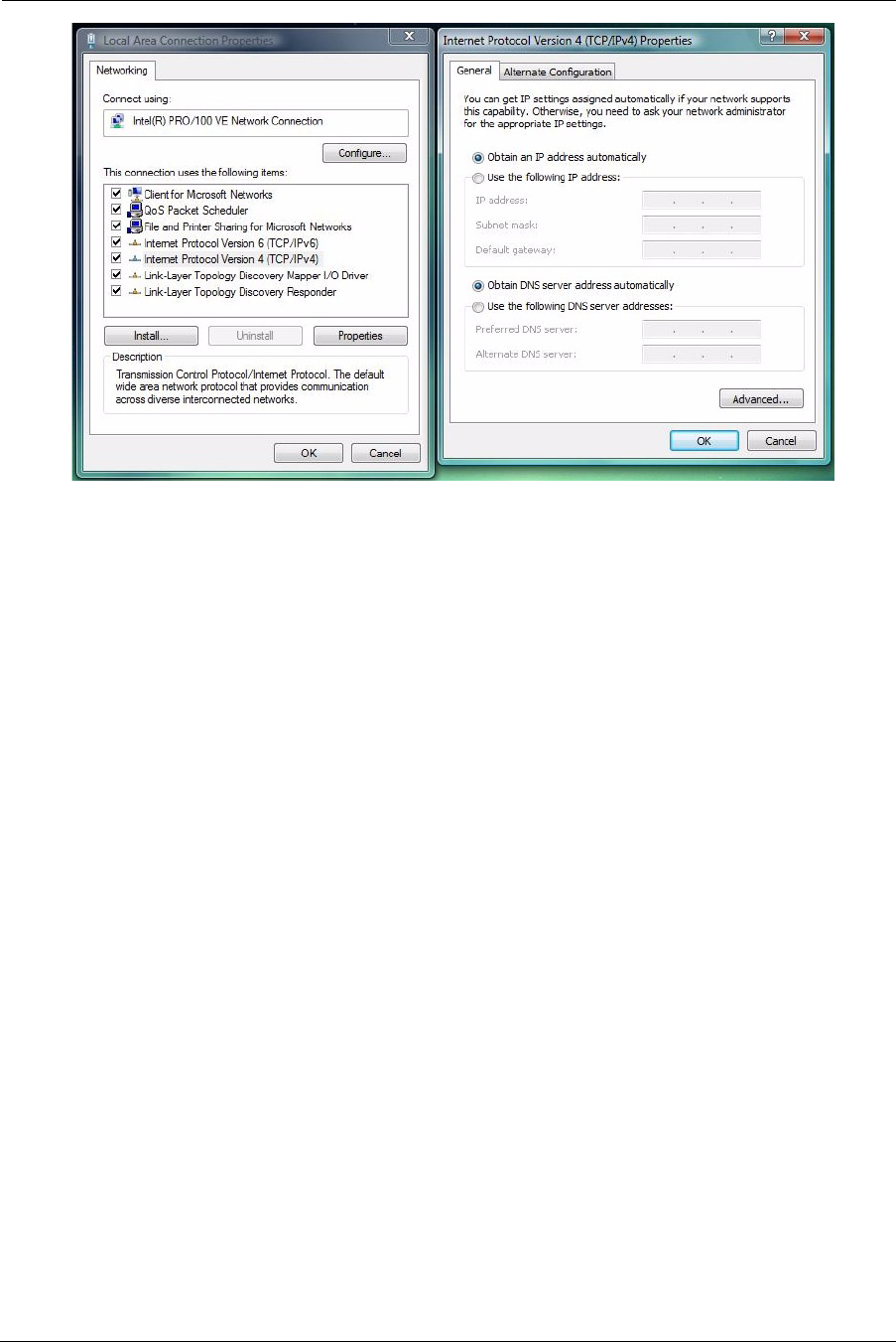
Microsoft Windows:
1. Navigate to the TCP/IP Properties control panel to configure the IP address using one of the suggested path-
ways that follow. Note that Windows Vista and Windows 7 obtain an IP address automatically by default.
You may not need to configure it at all.
Windows 7 follows a path like this: Start menu -> Control Panel -> Network and Sharing Center -> Change
adapter settings -> Local Area Connection -> Change settings of this connection -> Local Area Connection
Properties -> Internet Protocol (TCP/IP) -> Properties
Windows XP follows a path like this: Start menu -> Settings -> Control Panel -> Network Connections -> Local
Area Connection -> Internet Protocol [TCP/IP] -> Properties
2. Select Obtain an IP address automatically.
3. Select Obtain DNS server address automatically, if available.
4. Remove any previously configured gateways, if available.
5. OK the settings. Restart if prompted.
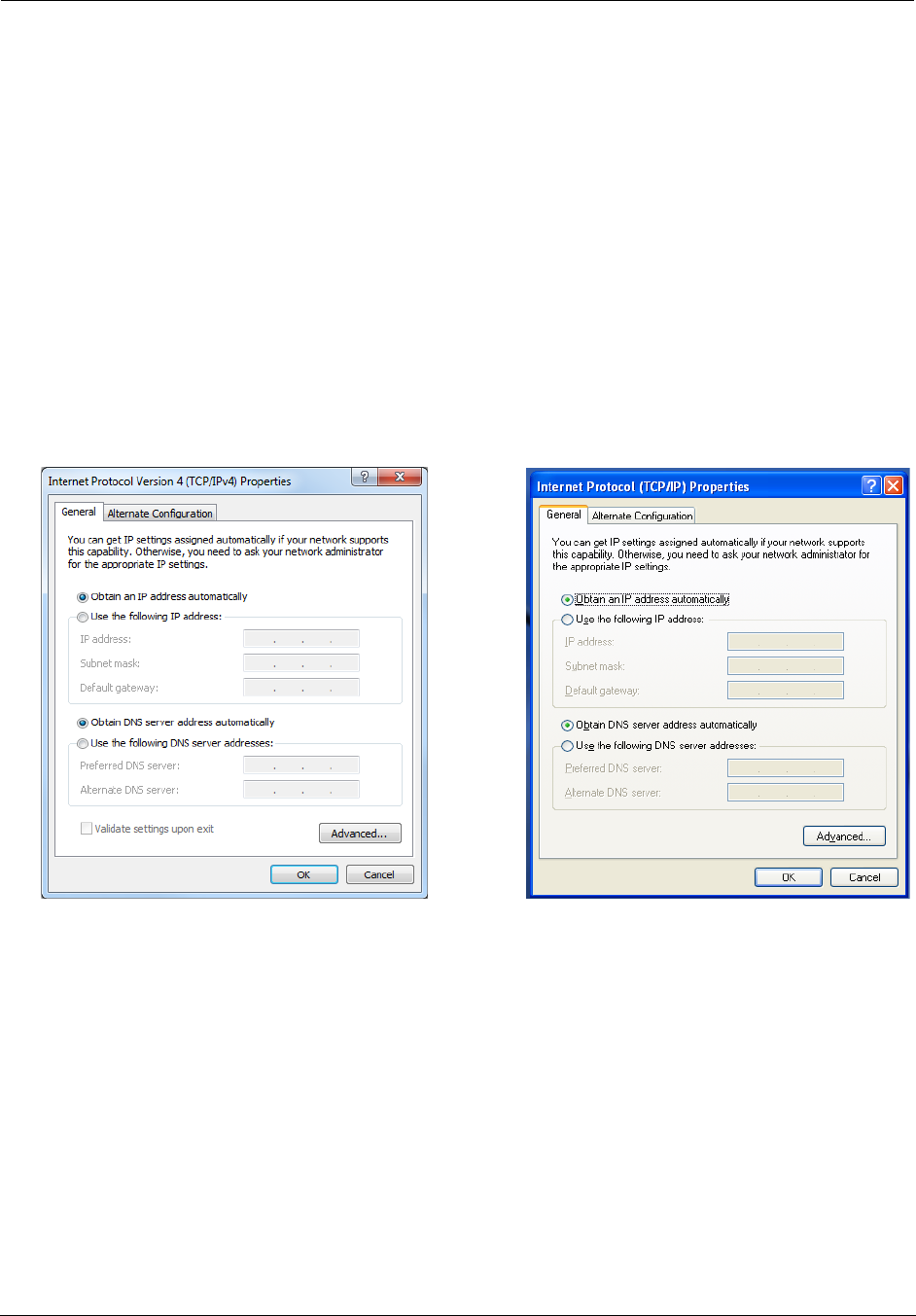
To check:
1. Open the Networking control panel and select Internet Protocol Version 4 (TCP/IPv4).
2. Click the Properties button. The Internet Protocol Version 4 (TCP/IPv4) Properties window should appear as
shown.
Windows 7 Windows XP
19
3. Set the radio buttons to the values shown above, and click the OK button.
Windows Vista
Administrator’s Handbook
20
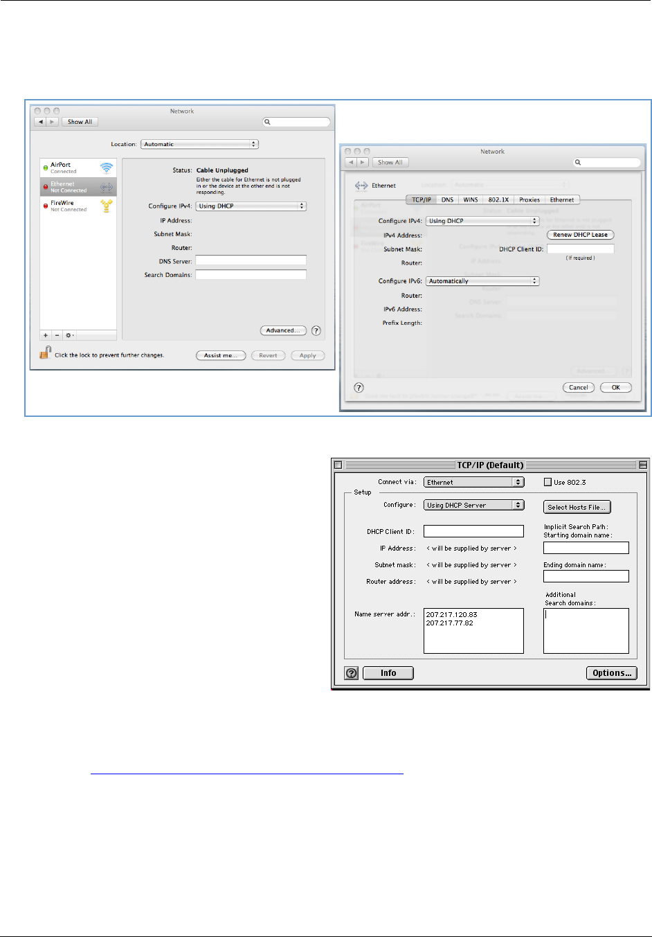
Macintosh MacOS 8 or higher or Mac OS X:
1. Access the TCP/IP or Network control panel.
Mac OS X follows a path like this:
Apple Menu -> System Preferences -> Network
MacOS Classic follows a path like this:
Apple Menu -> Control Panels -> TCP/IP Control
Panel
2. Select Ethernet.
3. Select Configure Using DHCP.
4. Close and save, if prompted.
Proceed to “Accessing the Web Management Interface” on page 21.
21
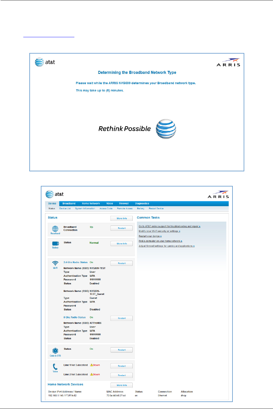
Accessing the Web Management Interface
1. Run your Web browser application, such as Firefox or Microsoft Internet Explorer, from the computer con-
nected to the NVG599 device.
2. Enter http://192.168.1.254 in the Location text box.
While the NVG599 is determining the broadband network type, the following screen appears.
The Device Status page appears.
Administrator’s Handbook
22
3. Check to make sure the Broadband and Service LEDs on your NVG599 device are lit GREEN to verify that the
connection to the Internet is active.
Congratulations! Your installation is complete. You can now surf to your favorite Web sites by typing a URL in
your browser’s location box or by selecting one of your favorite Internet bookmarks.
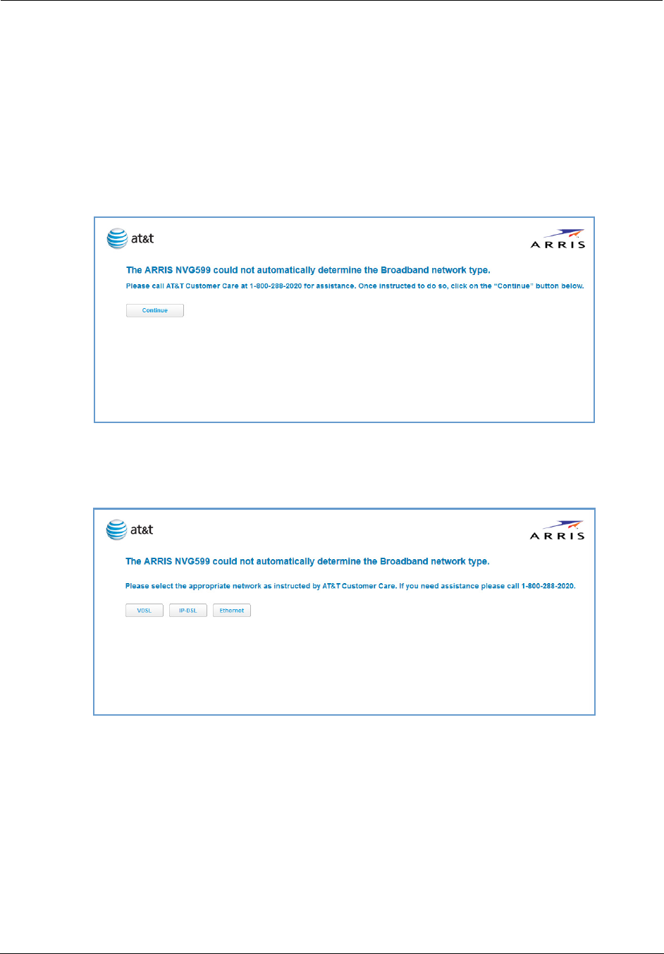
Broadband Network Redirect Pages
After a few minutes, if the broadband network cannot be determined, the following screen appears. Contact
AT&T Customer Care at the number shown on your screen for assistance.
If you click the Continue button, the following screen appears. Here you can manually select the broadband
network type, if you know it.
23
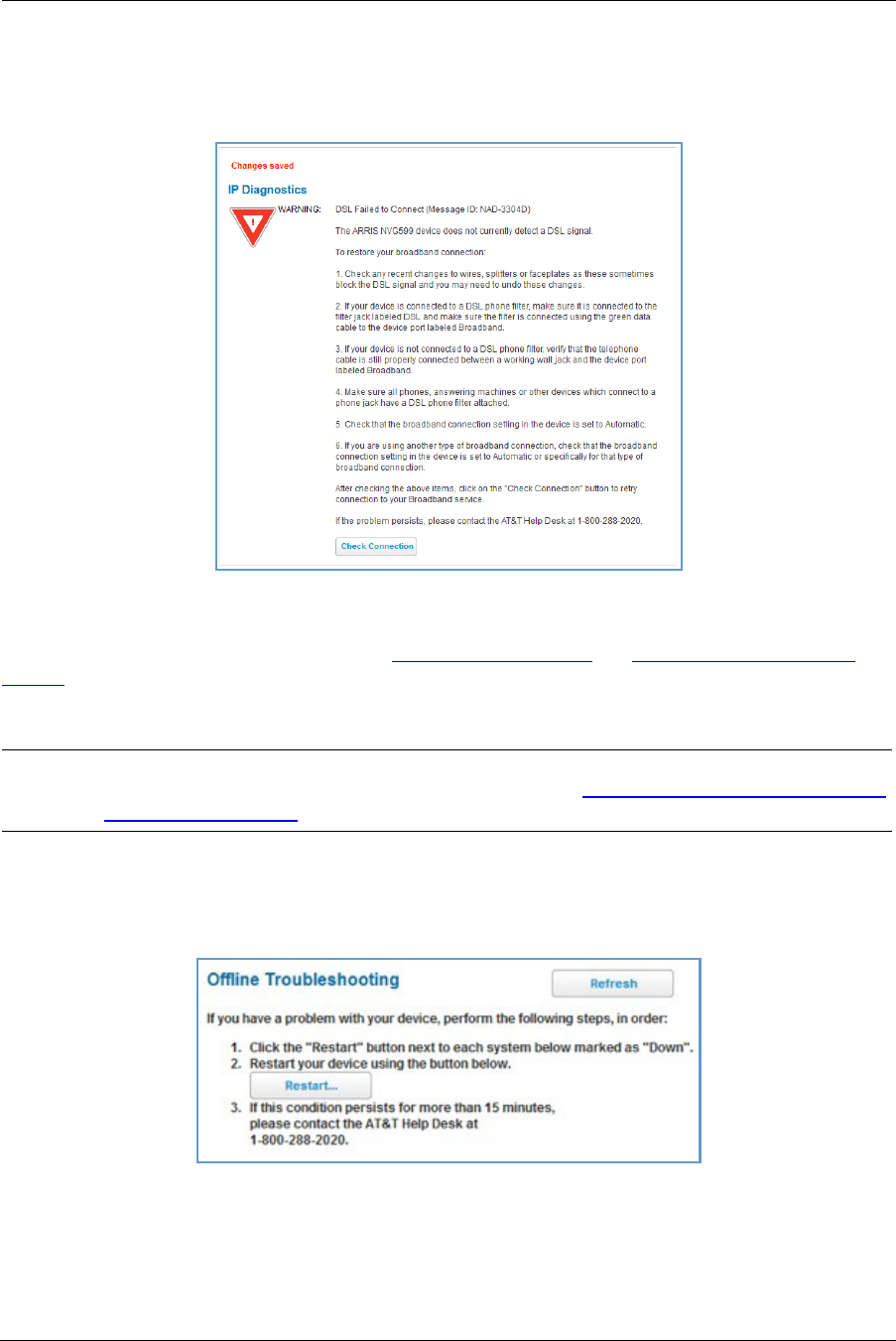
IP Diagnostics Page Redirect
In the event that your connection to the Internet fails, the Broadband LED on your NVG599 device flashes RED
and you are redirected to the IP Diagnostics page.
Follow the on-screen troubleshooting suggestions.
For additional troubleshooting information, see “Diagnostics” on page 77 and “Basic Troubleshooting” on
page 87.
When your connection is restored or the problem is resolved, the Broadband LED turns GREEN.
Offline Troubleshooting
If the WAN is down, the following information is displayed at the top of the page:
NOTE:
For AT&T this function is enabled by default. See the CLI command “set management lan-redirect enable
[ off | on ]” on page 149.
Administrator’s Handbook
24
Device Status Page
After you have performed the basic Easy Login configuration, any time you log in to your NVG599 you will
access the NVG599 Home page.
To access the Home page, type http://192.168.1.254 in your Web browser’s location box.
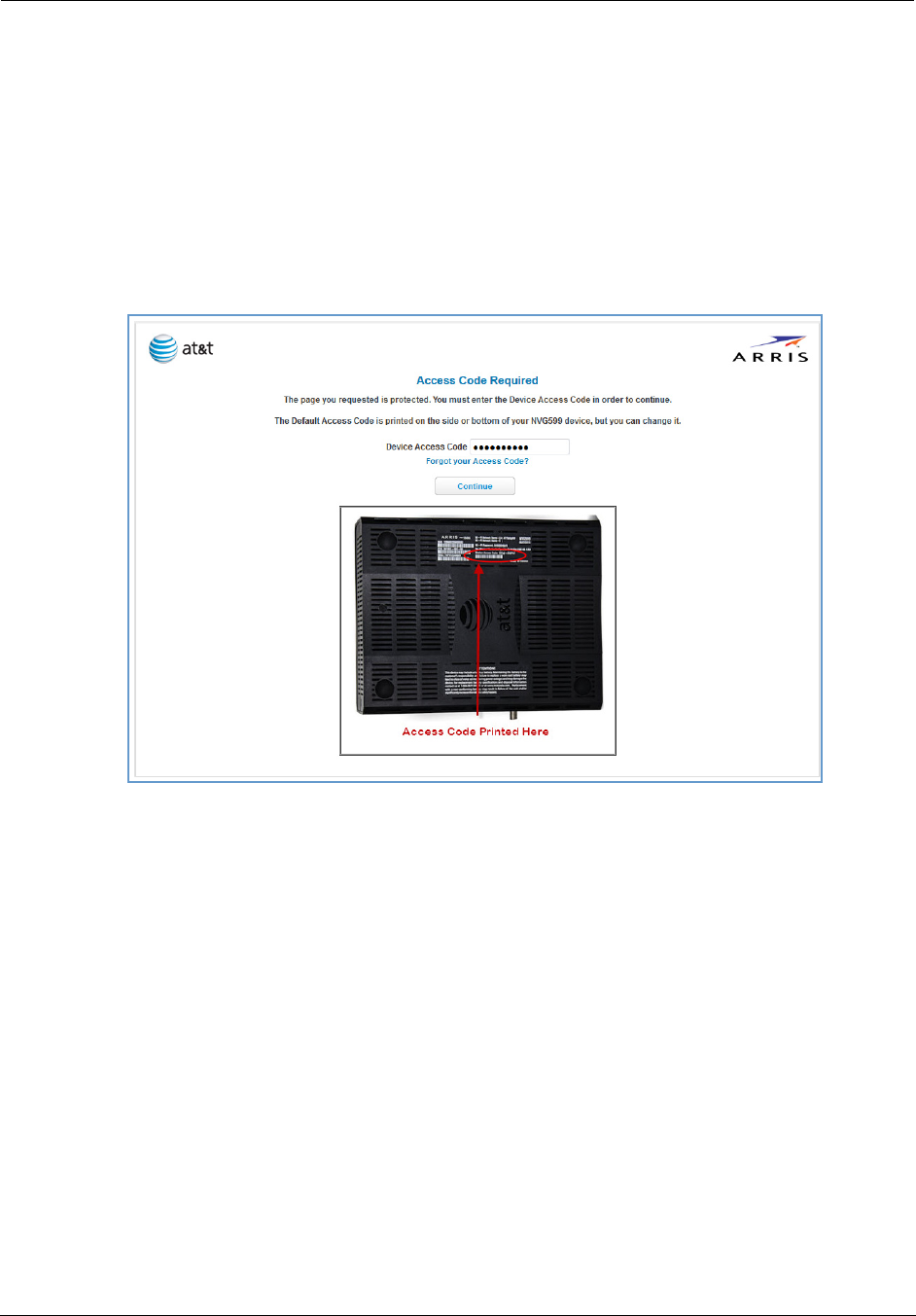
Device Access Code
On the Device Status page, you may be required to provide your device access code to access the Web
management configuration pages. The device access code is unique to your device. It is printed on a label on
the side of the NVG599.
Enter your device access code and click the Continue button.
25
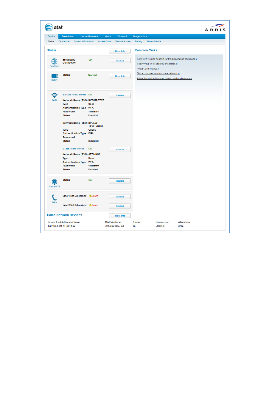
The Device Status page appears.
DeviceStatusWindow
Administrator’s Handbook
26
The Device Status page displays the following information in the center section:
Some fields may or may not be displayed, depending on your particular setup.
The Diagnostics button will connect you to the Troubleshoot page. See “Diagnostics” on page 77.
The frame at right displays some links to commonly performed tasks for easy access.
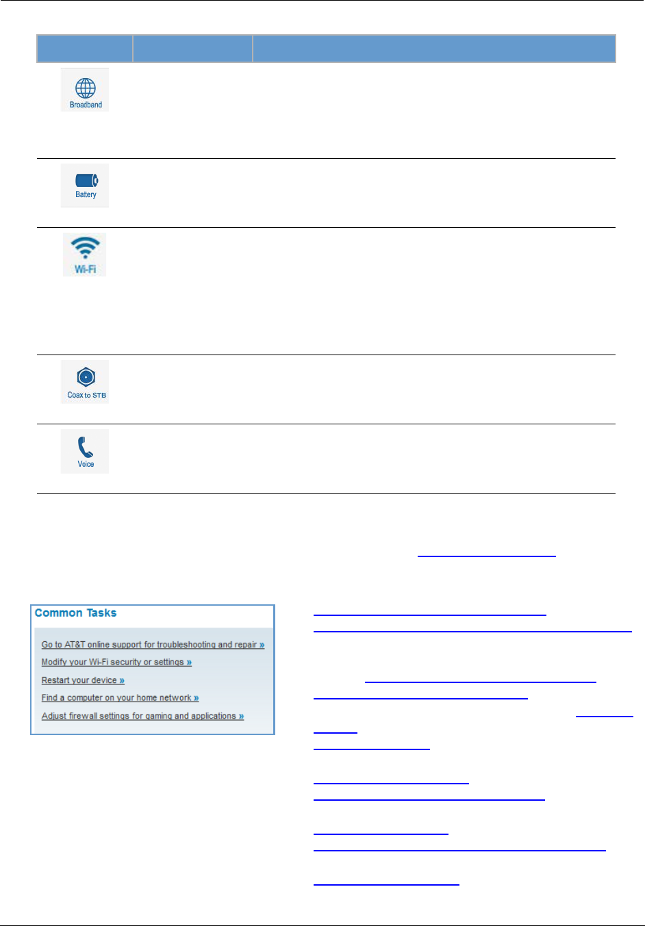
(icon) Field Description
(Broadband)
Broadband
Connection
Waiting for DSL is displayed while the NVG599 is training. This
should change to Up within two minutes.
Up is displayed when the ADSL line is synched and the session is
established.
Down indicates inability to establish a connection; possible line fail-
ure.
(Battery)
Status May display any of these values: Normal, Low Battery,
Charging, Warning: No battery or battery has no
charge or Warning: Battery backup mechanism has a
fault.
(WiFi)
Status Your wireless signal may be On or Off.
Network ID (SSID) The name or ID that is displayed to a client scan. The default SSID for
the NVG599 is attxxx where xxx is the last 3 digits of the serial
number located on the side of the NVG599.
Authentication Type The type of wireless encryption security in use. May be Disabled,
WPA, WEP, Default Key, or Manual.
Network Key Wireless network encryption key in use.
(Coax to STB)
Status Off or On.
(Voice)
Line 1 Indication of VoIP or other phone connection.
Line 2 Indication of VoIP or other phone connection.
Display additional troubleshooting steps » - OR -
Go to AT&T online support for troubleshooting and repair
This link will connect you to the IP Diagnostics page with
help for troubleshooting and the AT&T Help Desk informa-
tion. See “IP Diagnostics Page Redirect” on page 23.
Modify your WiFi security or settings »
This link will connect you to the WiFi page. See “WiFi” on
page 43.
Restart your device »
This link will connect you to the Restart Device page. See
“Restart Device” on page 33.
Find a computer on your home network »
This link will connect you to the Device List page. See
“Device List” on page 28.
Adjust firewall settings for gaming and applications »
This link will connect you to the NAT/Gaming page. See
“NAT/Gaming” on page 67.
27
Tab Bar
The tab bar is located at the top of every page, allowing you to move freely about the site.
The tabs reveal a succession of pages that allow you to manage or configure several features of your Gateway.
Each tab is described in its own section.
Help
Online Help for your device is available in the rightmost frame on every page in the Web interface. For
example, the Help section at right is displayed on the System Information page.
Links Bar
The links bar appears at the top of each page, allowing you to configure aspects of the features displayed on
the page. For example, the links bar on the Home Summary page is as shown below:
The links bar on the Device Status page includes the following links. For more information about each link, see
the related section in this guide.
Status (see page 24)
Device List (see page 28)
Administrator’s Handbook
28
System Information (see page 29)
Access Code (see page 30)
Remote Access (see page 31)
Battery (see page 32)
Restart Device (see page 33)
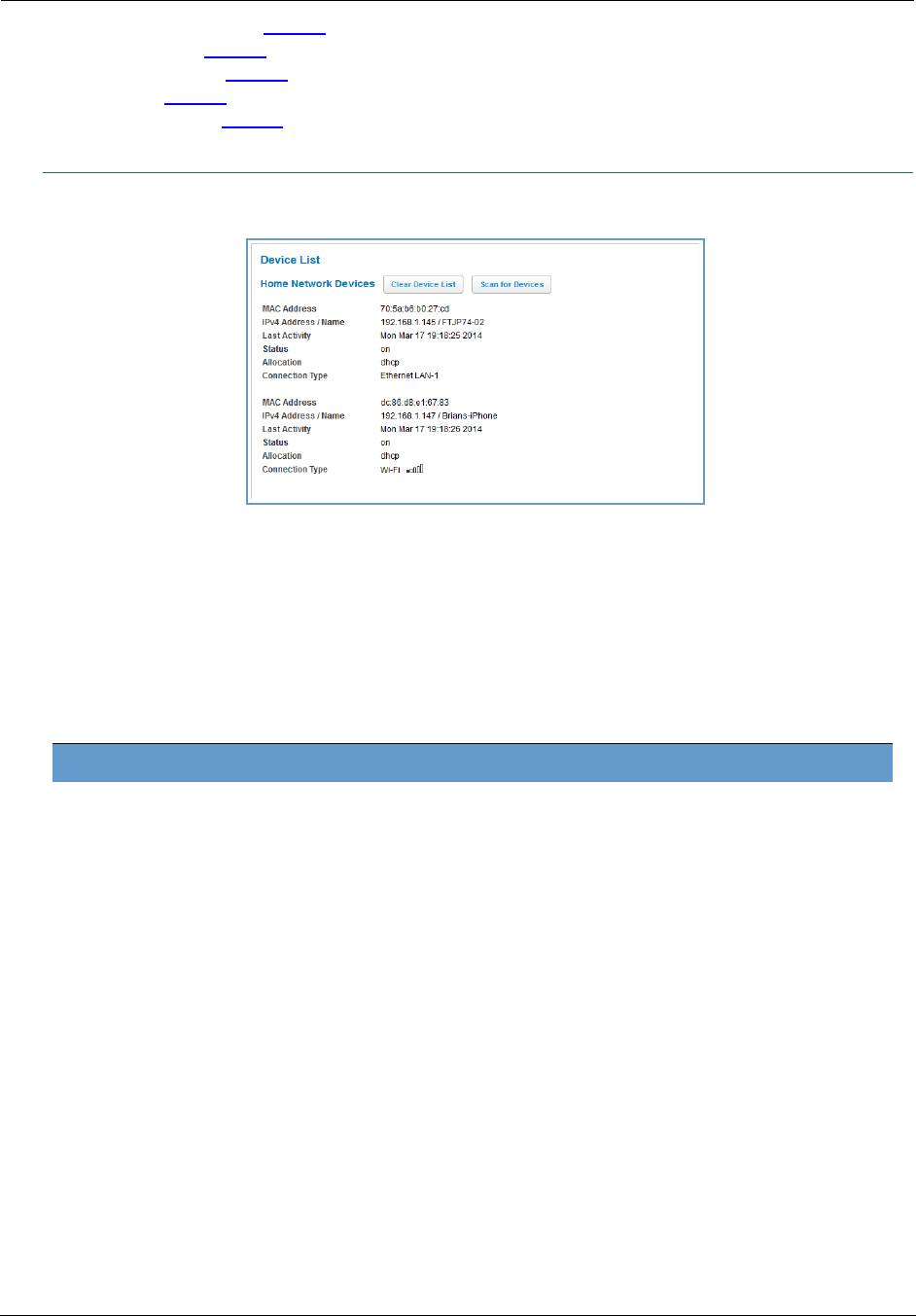
Link: Device List
When you click the Device List link, the Device List page appears.
The page displays the following summary information for each home network device connected to the NVG599
device on your local area network: IPv4 address, network name, MAC address, and other status information.
Home Network Devices
MAC Address Client device’s unique hardware address.
IPv4 Address / Name Client device’s IP address or device network name.
Last Activity Date and time of last traffic for this client device.
Status May be off or on.
Allocation Type of IP address assignment, for example, static or DHCP.
Connection Type Type of connection, for example, Ethernet or WiFi.
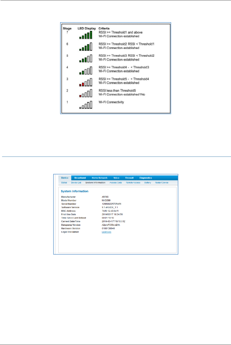
29
For WiFi client connections, the Device List page displays the familiar bars indicating signal strength, as follows:
Click the Clear Device List button to update the Home Network Devices summary.
Click the Scan for Devices button to seek out other devices that have been connected since the last Home
Network Devices summary update.
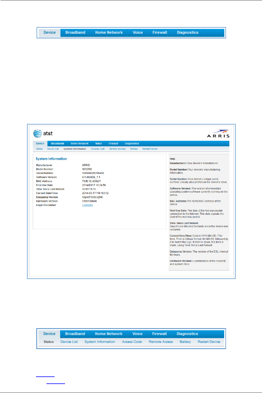
Link: System Information
When you click the System Information link, the System Information page appears.
Administrator’s Handbook
30
The page displays the following information:
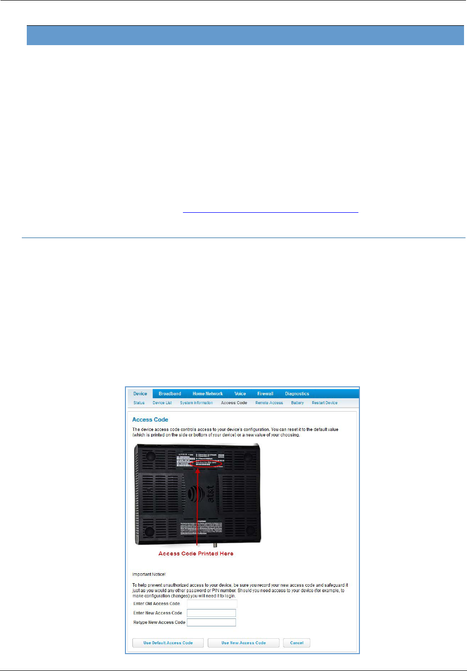
Link: Access Code
When you click the Access Code link, the Access Code page appears and allows changes to the code that
controls access to your device’s configuration. Access to your NVG599 device is controlled through an account
named Admin. The default Admin password for your device is the unique access code printed on the label on
the side of your device.
As the Admin, you can change this password to one of your own choosing between 8 and 20 characters long.
The new password must include two characters from any these categories: alpha, number, and special
characters.
Example: “fru1tfl13s_likeabanana”
System Information
Manufacturer Manufacturer’s identifier name.
Model Number Manufacturer’s model number.
Serial Number Unique serial number of your device.
Software Version Version number of the current embedded software in your device.
MAC Address Unique hardware address of this NVG599 unit.
First Use Date Date and time the NVG599 device is first used. This field changes to the current date
and time after a reset to factory defaults.
Time Since Last Reboot Elapsed time since last reboot of the device in days:hr:min:sec.
Current Date/Time Current system date and time in days:hr:min:sec.
Datapump Version Underlying operating system software datapump version.
Legal Disclaimer Clicking the Licenses link displays a listing of software copyright attributions, also
shown in “Copyright Acknowledgments” on page 189.
31
Enter your old access code, your new access code, and click the Use New Access Code button. The new access
code takes effect immediately.
You can always return to the original default password by clicking the Use Default Access Code button.
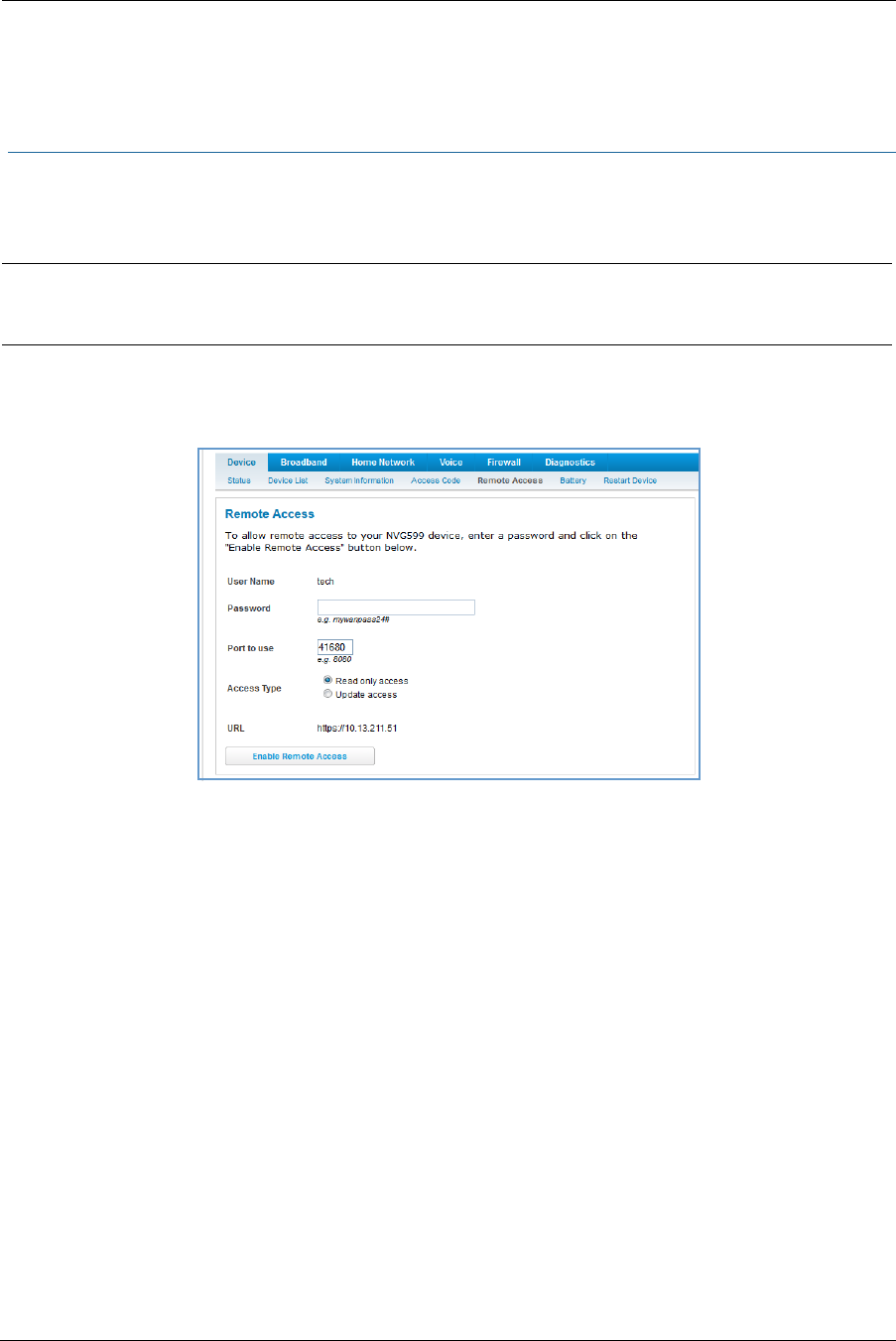
Link: Remote Access
The Remote Access page lets you grant access to your NVG599 device to other users on the WAN. This function
can be used for advanced troubleshooting or remote configuration.
If remote access is not currently enabled, the Remote Access page will let you configure and enable it. If
remote access has been enabled, the Remote Access page will indicate that, and provides a button to disable
it.
To enable remote access:
1. Type a password in the Password field. This password must be at least 8 characters long, and must include at
least two of the following types of characters:
Alphabetic (letter) characters
Numeric (number) characters
Special characters (! @ # $ % ^ & * , etc)
2. If necessary, set a custom port number for secure HTTP access to the NVG599 remote access session in the
Port Value field.
3. Click the radio button that describes the type of remote access to allow:
Read only access - to allow the remote access session to view, but not change, the configuration and col-
lected statistics of the gateway.
Update access - to allow the session to make changes to the gateway’s configuration.
4. Click the Enable Remote Access button.
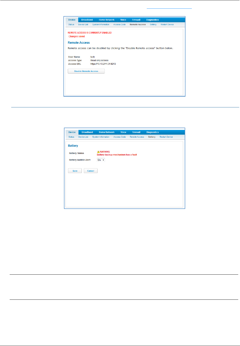
The NVG599 updates the Remote Access page and displays the current remote access settings, shows the URL
that a remote access client must use to connect to the remote access session, and provides a button for ending
the remote access session. The remote access client will need to connect to the URL shown on the Remote
Access page, and will need to log in with the user name “tech” and with the password configured when access
was enabled.
WARNING:
Enabling remote access allows anyone who knows or can determine the password, port ID, and URL
(address) of your NVG599 device to view any configuration settings or change the operation of your gateway.
Administrator’s Handbook
32
To end (disable) an existing remote access configuration, click the Disable Remote Access button, as shown
below:
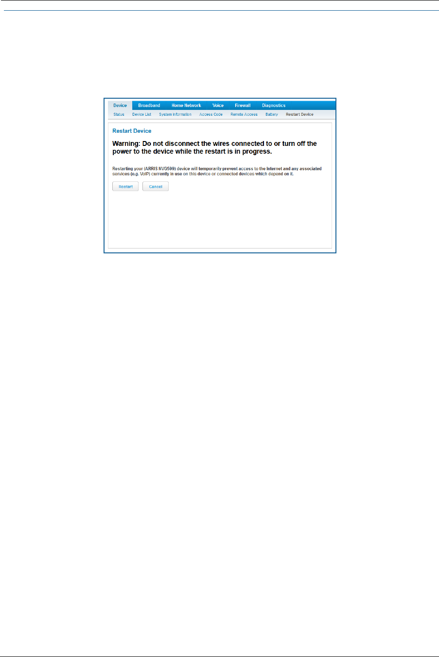
Link: Battery
The Battery page shows the condition and status of the NVG599 internal battery, and provides control over the
battery condition audible alarm.
The battery condition audible alarm provides an on-hook ringing signal on a connected telephone if the
NVG599 battery needs recharging or replacing. This alarm uses a distinctive “splash” ring pattern and a battery
notification message on phones with caller ID displays or announcers. Additionally, the NVG599 provides an
off-hook voice notification to the subscriber if the NVG599 battery is low (and needs recharging) or faulty (and
needs replacing). After playing the recorded voice notification, the NVG599 provides a dial tone.
The alarm is triggered when the NVG599 determines that the installed battery is:
Below 35% charge and in need of recharging, or
Unable to charge past 80% of capacity and in need of replacing.
To change the alarm setting, click the Battery Audible Alert drop-down menu, and select the setting (On or Off)
for the alarm. Click the Save button to save the new settings, or Cancel to discard them.
Note:
A subscriber may interrupt the voice notification by dialing. The voice notification may be turned off by a
subscriber phone dialing “*#103”. This capability is included in the VOIP digit map with the parameter
*#103<:@C06>
33
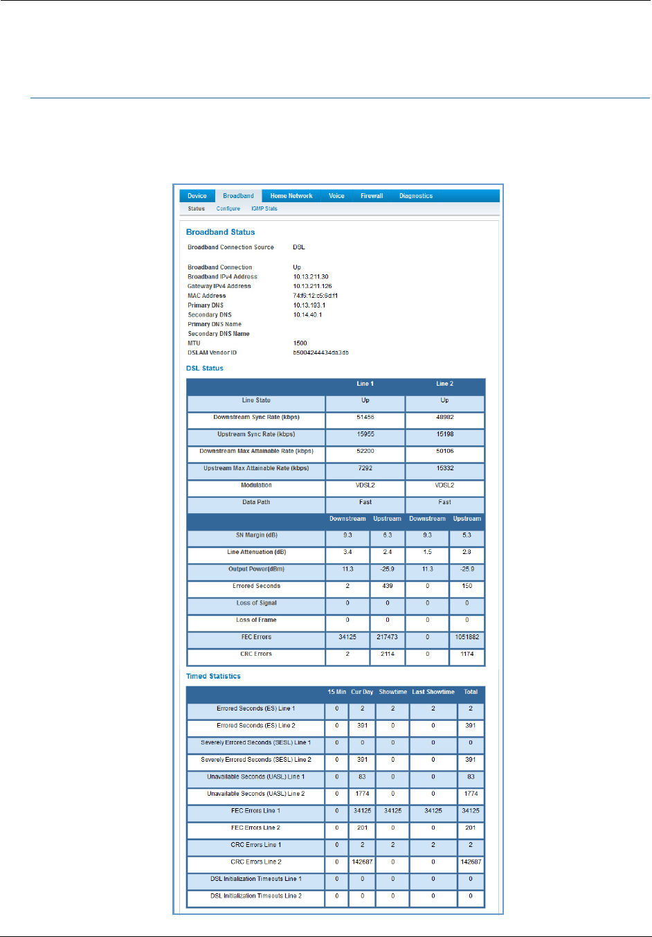
Link: Restart Device
When the NVG599 is restarted, it will disconnect all users, initialize all its interfaces, and load the operating
system software.
In some cases, when you make configuration changes, you may be required to restart for the changes to take
effect.
Administrator’s Handbook
34
Broadband Tab
Links available on the Broadband tab provide access to pages that allow you to view information about the
broadband connection and configure connection details.
Link: Broadband Status
When you click the Broadband tab, the Broadband Status page is the first to appear.

35
The Status page displays information about the NVG599 device’s WAN connection(s) to the Internet.
Broadband Status
Broadband Connection
Source
The communications technology providing the NVG599 broadband uplink.
Broadband Connection May be Up (connected) or Down (disconnected).
Broadband IPv4 Address The public IP address of your device, whether dynamically or statically assigned.
Gateway IPv4 Address Your ISP's gateway router IP address.
MAC Address Your device’s unique hardware address identifier.
Primary DNS The IP address of the primary Domain Name System (DNS) server.
Secondary DNS The IP address of the backup DNS server, if available.
Primary DNS Name The name of the primary DNS server.
Secondary DNS Name The name of the backup DNS server, if available.
MTU Maximum transmittable unit before packets are broken into multiple packets.
DSL Status (for each line)
Line State May be Up (connected) or Down (disconnected).
Downstream Sync Rate The rate at which your connection can download (receive) data on your DSL line, in
kilobits per second.
Upstream Sync Rate The rate at which your connection can upload (send) data on your DSL line, in kilobits
per second.
Modulation Method of regulating the DSL signal. DMT (discrete multi-tone) allows connections to
work better when certain radio transmitters are present.
Data Path Type of path used by the device's processor.
Downstream and Upstream Statistics (DSL WAN)
SN Margin (db) Signal-to-noise margin, in decibels. Reflects the amount of unwanted noise on the DSL
line.
Line Attenuation Amount of reduction in signal strength on the DSL line, in decibels.
Output Power (dBm) Measure of power output in decibels (dB) referenced to one milliwatt (mW).
Errored Seconds The number of uncorrected seconds after being down for seven consecutive seconds.

Administrator’s Handbook
36
Loss of Signal The absence of any signal for any reason, such as a disconnected cable or loss of
power.
Loss of Frame A signal is detected but the device cannot sync with signal because of mismatched
protocols, wrong ISP connection configuration, or faulty cable.
FEC Errors Forwarded Error Correction errors. Count of received errored packets that were fixed
successfully without a retry.
CRC Errors Number of times data packets have had to be resent because of errors in transmission
or reception.
Ethernet Statistics (Ethernet WAN)
Line State Up or Down
Current Speed Line speed
Current Duplex Full- or half-duplex
Receive Packets Number of packets received
Transmit Packets Number of packets sent
Receive Bytes Number of bytes received
Transmit Bytes Number of bytes sent
Receive Unicast Receive Unicast statistics
Transmit Unicast Transmit Unicast statistics
Receive Multicast Receive Multicast statistics
Transmit Multicast Transmit Multicast statistics
Receive Drops Received packets dropped
Transmit Drops Sent packets dropped
Receive Errors Count of received errored packets that were fixed successfully without a retry.
Transmit Errors Number of times data packets have had to be resent due to errors in transmission.
Collisions Count of packet collisions.
Aggregated Information
Bonded Downstream Rate The bonded channel receive rate.
Bonded Upstream Rate The bonded channel transmit rate.
IPv6
Status May be Enabled or Unavailable.
Global Unicast IPv6 Address The public IPv6 address of your device, whether dynamically or statically assigned.
Border Relay IPv4 Address The public IPv4 address of your device.
IPv4 Statistics
Transmit Packets IPv4 packets transmitted.
Transmit Errors Errors on IPv4 packets transmitted.
Transmit Discards IPv4 packets dropped.
IPv6 Statistics
Transmit Packets IPv6 packets transmitted.
Transmit Errors Errors on IPv6 packets transmitted.
Transmit Discards IPv6 packets dropped.
37
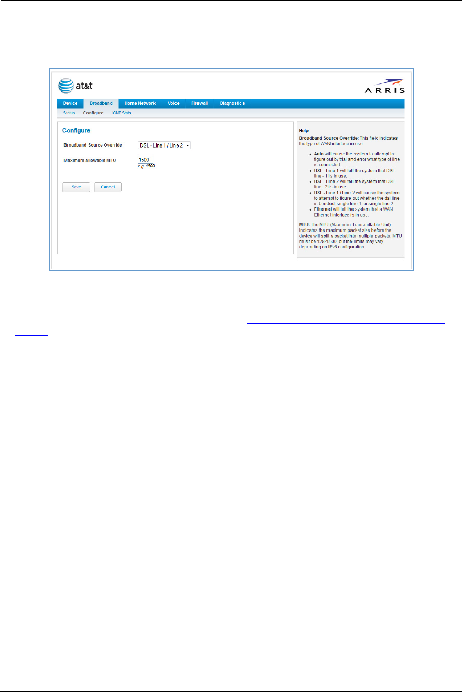
Link: Configure
When you click the Configure link, the Broadband Configure screen appears. Here you can reconfigure your
type of broadband connection should it change in the future.
Broadband Source Override - Auto (automatically detected), DSL - Line 1, DSL - Line 2, DSL - Line 1 / Line -2
(Bonded), or Ethernet WAN.
If you switch from DSL to Ethernet or from Ethernet to DSL, the device will prcoceed to reconnect as in its ini-
tial connection to the Internet, as described earlier. See “Accessing the Web Management Interface” on
page 21.
The WAN connection is automatically configured. However, you can adjust the Maximum allowable MTU
(maximum transmittable unit) value, if your service provider suggests it. The default 1500 is the maximum
value, but some services require other values (1492 is common).
If you make any change here, click the Save button.
Administrator’s Handbook
38
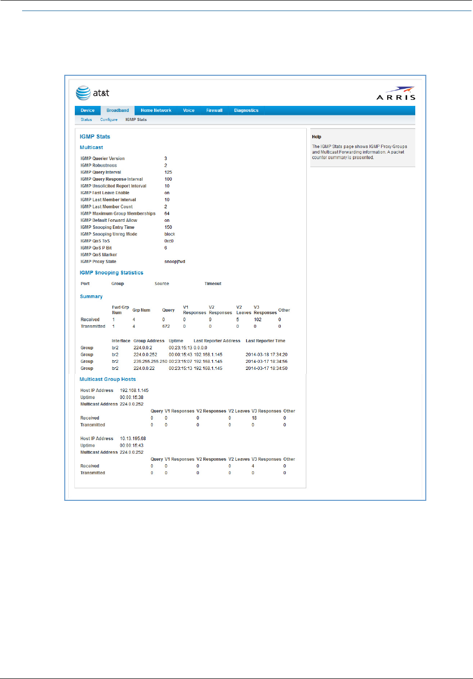
Link: IGMP Stats
When you click the IGMP Stats link, the IGMP Stats screen appears. The IGMP statistics screen reports IGMP
proxy groups and multicast forwarding information. It also displays a packet counter.
39
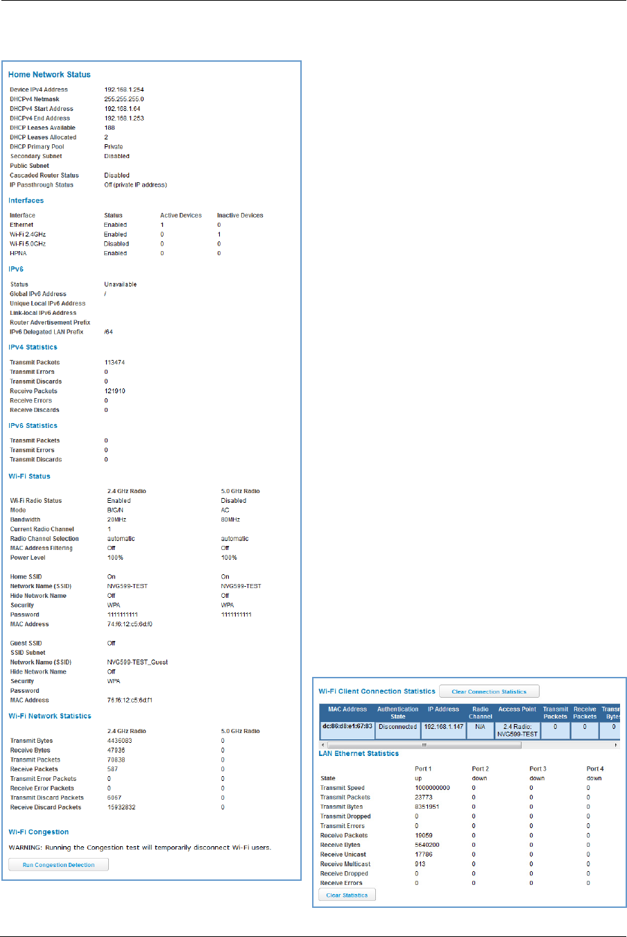
Home Network Tab
When you click the Home Network tab, the Home Network Status page appears.
The Home Network Status page displays information
about the NVG599 device’s local area network.
If you click the Run Congestion Detection button, the
device will generate statistics for each of the 11
channels available, displaying:
Channel number
AP (access point) count
Congestion score (1 - 10) - Note that higher val-
ues mean lower congestion.
The wireless congestion feature provides simple data to
the user to show the level of network congestion in
each wireless channel. This data can be used to
determine router placement or to determine which
channels to avoid.
The display tells the user how many access points (APs)
are active within each channel, and provides a score of
1 - 10 to indicate how clear the channel is. A higher
score indicates less congestion in a channel; thus, a 10
indicates a channel extremely clear of wireless traffic
and noise. Alternatively, a score of 1 indicates more
severe congestion in a channel.
You can clear the current statistics information by
clicking the Clear Statistics button.

Administrator’s Handbook
40
Home Network Status
Device IPv4 Address The NVG599 device’s own IP address on the network.
DHCP Netmask The device’s own netmask on the network.
DHCPv4 Start Address The starting IP address of the DHCP range served by the device.
DHCPv4 End Address The ending IP address of the DHCP range served by the device.
DHCP Leases Available The number of IP addresses of the DHCP range available to be served by the device.
DHCP Leases Allocated The number of IP addresses of the DHCP range currently being served by the device.
DHCP Primary Pool Source pool of the IP addresses served by the NVG599 device, Public or Private.
IPv6
Status May be Enabled or Unavailable.
Global IPv6 Address The public IPv6 address of your device, whether dynamically or statically assigned.
Link-local IPv6 Address The private IPv6 address of your device, whether dynamically or statically assigned.
Router Advertisement Prefix The IPv6 prefix to include in router advertisements.
IPv6 Delegated LAN Prefix The IPv6 network address prefix that identifies the NVG599 network.
IPv4 Statistics
Transmit Packets IPv4 packets transmitted.
Transmit Errors Errors on IPv4 packets transmitted.
Transmit Discards IPv4 packets dropped.
IPv6 Statistics
Transmit Packets IPv6 packets transmitted.
Transmit Errors Errors on IPv6 packets transmitted.
Transmit Discards IPv6 packets dropped.
WiFi Status
WiFi Radio Status Status of the Wi-Fi radio: Enabled or Disabled.
Mode 2.4 Ghz radio may be 802.11B only, 802.11G only, 802.11N only, 802.11 B/G or 802.11
B/G/N.
5.0 Ghz radio may be 802.11A, 802.11AC only, 802.11N only or 802.11AC (i.e.
802.11N/AC) as well.
Bandwidth The capacity of the wireless LAN to carry traffic in megahertz.
Current Radio Channel The radio channel that your Wi-Fi network is broadcasting on.
Radio Channel Selection May be set to automatic or manually selected.
MAC Address Filtering May be either On or Off. If On, you can accept or block client devices from your WLAN
based on their MAC address.
Power Level May be adjusted up to 100%, lower if multiple wireless access points are in use, and
might interfere with each other.
WiFi MAC Address Shows the information of the MAC address of the wireless subsystem.
User SSID May be either On or Off for either frequency.
Guest SSID May be either On or Off for the 2.4 Ghz radio only.
Network Name (SSID) The name or ID that is displayed to a client scan. The default SSID for the NVG599 is
attxxx where xxx is the last 3 digits of the serial number located on the side of the
NVG599 device.
Hide SSID May be either On or Off. If On, your SSID will not appear in a client scan.
41
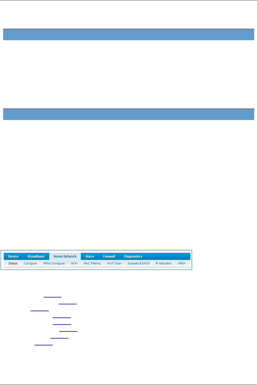
The links at the top of the Home Network page provide access to a series of pages that allow you to configure
and monitor features of your device.
The links bar on the Home Network page includes the following links. For more information about each link,
see the related section in this guide.
Configure (see page 42)
HPNA Configure (see page 42)
Wifi (see page 43)
MAC Filtering (see page 47)
Wireless Scan (see page 48)
Subnets & DHCP (see page 49)
IP Allocation (see page 50)
HPNA (see page 52)
Wireless Security The type of wireless encryption security in use. May be Disabled, WPA, WEP,
Default Key, or Manual.
Password Shows the information of the security encryption key in use.
WiFi Network Statistics
Transmit Bytes Number of bytes transmitted on the Wi-Fi network.
Receive Bytes Number of bytes received on the Wi-Fi network.
Transmit Packets Number of packets transmitted on the Wi-Fi network.
Receive Packets Number of packets received on the Wi-Fi network.
Transmit Error Packets The number of errors on packets transmitted on the Wi-Fi network.
Receive Error Packets The number of errors on packets received on the Wi-Fi network.
Transmit Discard Packets The number of packets transmitted on the Wi-Fi network that were dropped.
Receive Discard Packets The number of packets received on the Wi-Fi network that were dropped.
LAN Ethernet Statistics
State May be Up or Down.
Transmit Speed The maximum speed of which the port is capable.
Transmit Packets The number of packets sent out from the port.
Transmit Bytes The number of bytes sent out from the port.
Transmit Dropped The number of packets sent out from the port that were dropped.
Transmit Errors The number of errors on packets sent out from the port.
Receive Packets The number of packets received on the port.
Receive Bytes The number of bytes received on the port.
Receive Unicast The number of unicast packets received on the port.
Receive Multicast The number of multicast packets received on the port.
Receive Dropped The number of packets received on the port that were dropped.
Receive Errors The number of errors on packets received on the port.
Administrator’s Handbook
42
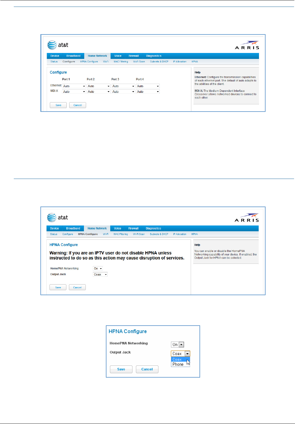
Link: Configure
When you click the Configure link, the Configure page for the Ethernet LAN appears.
For each Ethernet Port, 1 through 4, you can select:
Ethernet – Auto (the default self-sensing rate), 10M full- or half-duplex, 100M full- or half-duplex, or 1G
full- or half-duplex.
MDI-X – Auto (the default self-sensing crossover setting), Off, or On.
Click the Save button.
Link: HPNA Configure
When you click the HPNA Configure link, the HPNA Configure page for the HomePNA network appears.
Here you can set HomePNA Networking On or Off.
If desired, you can also set the Output Jack, as either the Coax jack or the Phone jack.
Click the Save button.
43
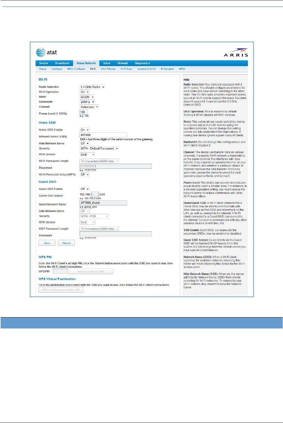
Link: WiFi
When you click the WiFi link, the WiFi page appears. The WiFi page displays the status of your wireless LAN
elements.
The WiFi page center section contains a summary of the configuration settings and operational status for the
wireless access point.
Summary Information
Field Status and/or Description
Radio Selection Display the settings for either the 2.4 Ghz or the 5.0 Ghz frequency radio.
WiFi Operation May be either On or Off.
Mode Wireless transmission mode. For the 2.4 Ghz radio, may be 802.11B only, 802.11G only,
802.11N only, 802.11 B/G or 802.11 B/G/N. For the 5.0 Ghz radio, may be 802.11AC as
well.
Bandwidth The capacity of the wireless LAN to carry traffic in megahertz, 20 or 40.
Channel The radio channel on which your Wi-Fi network is broadcasting.
Power Level May be adjusted up to 100%, lower if multiple wireless access points are in use, and
might interfere with each other.

Administrator’s Handbook
44
WiFi Operation – Automatically enabled by default. If you deselect the checkbox, the WiFi options are dis-
abled, and the wireless access point will not provide or broadcast its wireless LAN services.
Mode – The drop-down menu allows you to select and lock the NVG599 into the wireless transmission mode
you want: A/C, B/G/N, B-only, B/G, G-only, or N-only.
For compatibility with clients using 802.11b (up to 11 Mbps transmission), 802.11g (up to 20+ Mbps),
802.11a (up to 54 Mbit/s using the 5 GHz band), or 802.11n (from 54 Mbit/s to 600 Mbit/s with the use of
four spatial streams at a channel width of 40 MHz), select B/G/N. To limit your wireless LAN to one mode or
the other, select the option that applies to your setup.
Bandwidth – Use a single 20-MHz channel (20MHz setting) , or combine two 20-MHz channels (40MHz set-
ting) to increase data speeds. The 40-MHz mode may only be selected if the Mode setting is 801.11 B/G/N
or 802.11 N-Only. To prevent interference with lower bandwidth clients, the wireless network will revert to
20MHz operation if non-compatible (802.11B, 802.11G, or 20-MHz 802.11N) clients are detected.
Channel – Channel (1 through 11, for North America) on which the network will broadcast. This is a fre-
quency range within the 2.4-Ghz or 5.0-Ghz band. The Automatic setting allows the wireless access point to
automatically determine the best channel for broadcast.
Power Level – Sets the wireless transmit power, scaling down the wireless access point’s wireless transmit
coverage by lowering its radio power output. Default is 100% power. Transmit power settings are useful in
large venues with multiple wireless routers where you want to reuse channels. Since there are only three
non-overlapping channels in the 802.11 spectrum, it helps to size the wireless access point cell to match the
location. This allows you to install a router to cover a small “hole” without conflicting with other routers
nearby.
Network Name (SSID) – Preset to a number unique to your unit. You can either leave it as is, or change it by
entering a freeform name of up to 32 characters, for example “Brian’s Wireless LAN.” In client PC software,
this might also be called the wireless ID. The Network Name is used to identify this particular wireless LAN.
Depending on their operating system or client wireless card, users must either:
• Select from a list of available wireless LANs that appear in a scanned list on their client.
• Enter this name on their clients in order to join this wireless LAN.
Hide SSID – If enabled, this mode hides the wireless network from the scanning features of wireless client
computers. Hiding the SSID prevents casual detection of your wireless network by unwanted neighbors and
passers-by. The gateway WLAN will not appear when clients scan for access points. If Hide SSID is enabled,
you must remember to enter your SSID when adding clients to the wireless LAN.
Security, WPA Version, WEP Key Length, Key – See “Wireless Security” on page 45.
User SSID Enable May be either On or Off for either frequency.
Guest SSID Enable May be either On or Off for the 2.4 Ghz radio only.
Network Name (SSID) The name or ID that is displayed to a client scan. The default SSID for the NVG599 is
attxxx where xxx is the last 3 digits of the serial number located on the side of the
device.
Hide SSID May be either Off or On. If On, your SSID will not appear in a client scan.
Security The type of wireless encryption security in use. May be OFF-No Privacy, WPA-
PSK, WEP, Default Key or Manual.
WPA Version If WPA is selected, may be Both, WPA-1, or WPA-2.
WEP Key Length May be 10 characters for 40/64-bit, or 26 characters for 128-bit WP encryption.
Key Here you can enter a manual encryption key.
WiFi Protected Setup (WPS) May be either On or Off.
General Information
NOTE:
If you choose to limit the operating mode to 802.11b or 802.11g only, clients using the mode you excluded
will not be able to connect.
NOTE:
While hiding the SSID may prevent casual discovery of your wireless network, enabling security is the only
true method of securing your network.
45
WiFi Protected Setup (WPS) – Not a security protocol. WPS is an easier way to add and securely configure
new clients to your WLAN. By default, Privacy is set to WiFi Protected Access (WPA-PSK) with a 12-character
security key. WPS allows you to securely share your exact security configuration with a new client that you
are adding to the WLAN, without needing to look up and type this security key. Clients can be added using
the WPS button on the router, or by entering the client WPS PIN on this page. Not all client wireless devices
support WPS. Refer to their documentation.
To add a client: Enter your WPS PIN and click the Submit button. Follow the instructions that came with your
wireless client.
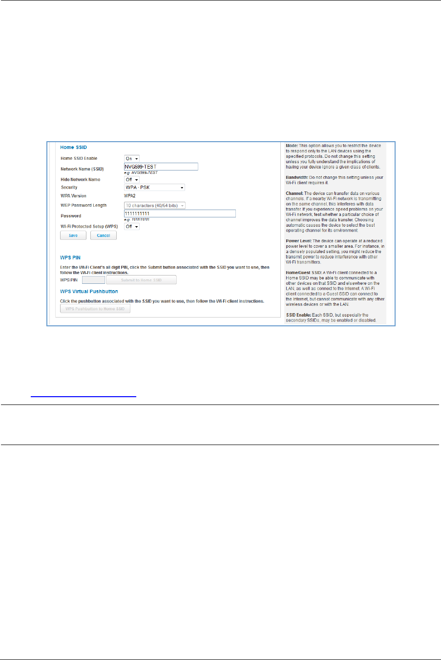
Wireless Security
By default, wireless security is set to WPA-PSK with a pre-defined WPA-Default Key.
Other options are available from the Security drop-down menu:
WEP - Manual: WEP security is a privacy option that is based on encryption between the router and any PCs
(clients) you have with wireless cards. For WEP-Manual encryption to work, both your wireless access point
and each client must share the same wireless ID (SSID), and both must be using the same encryption keys.
See “WEP-Manual” on page 46.
WPA-PSK: Allows you to enter your own key, the most secure option for your wireless network. The key can
be between 8 and 63 characters, but for best security it should be at least 20 characters. If you select WPA-
PSK as your privacy setting, the WPA Version drop-down menu allows you to select the WPA version(s) that
will be required for client connections. Choices are:
• Both, for maximum interoperability
• WPA-1, for backward compatibility
• WPA-2, for maximum security
All clients must support the version(s) selected in order to successfully connect. Be sure that your Wi-Fi cli-
ent adapter supports this option. Not all Wi-Fi clients support WPA-PSK.
OFF - No Privacy: Disables privacy on your network, allowing any wireless users to connect to your wireless
LAN. Select this option if you are using alternative security measures such as VPN tunnels, or if your network
is for public use.
Click the Save button.
NOTE:
WEP is a less current and less secure authentication method than WPA-PSK. It may be required if your wire-
less clients do not support WPA.

Administrator’s Handbook
46
WEP-Manual
You can provide a level of data security by enabling WEP (Wired Equivalent Privacy) for encryption of network
data. You can enable 40- or 128-bit WEP Encryption (depending on the capability of your client wireless card)
for IP traffic on your LAN.
WEP - Manual allows you to enter your own encryption keys manually. This is a difficult process, but only
needs to be done once. Avoid the temptation to enter all the same characters.
Key Length: The drop-down menu selects the length of each encryption key. The longer the key, the stronger
the encryption and the more difficult it is to break the encryption.
Key: You must enter a key using hexadecimal digits. For 40/64-bit encryption, you need ten digits; 26 digits for
128-bit WEP. Hexadecimal characters are 0 – 9, and a – f.
Examples:
40 bits: 02468ACE02
128 bits: 0123456789ABCDEF0123456789
Any WEP-enabled client must have an identical key of the same length as the router, in order to successfully
receive and decrypt the traffic. Similarly, the client also has a default key that it uses to encrypt its
transmissions. In order for the router to receive the client’s data, it must likewise have the identical key of the
same length.
Click the Save button.
NOTE:
WEP is a less current and less secure authentication method than WPA-PSK. It may be required if your wire-
less clients do not support WPA.
47
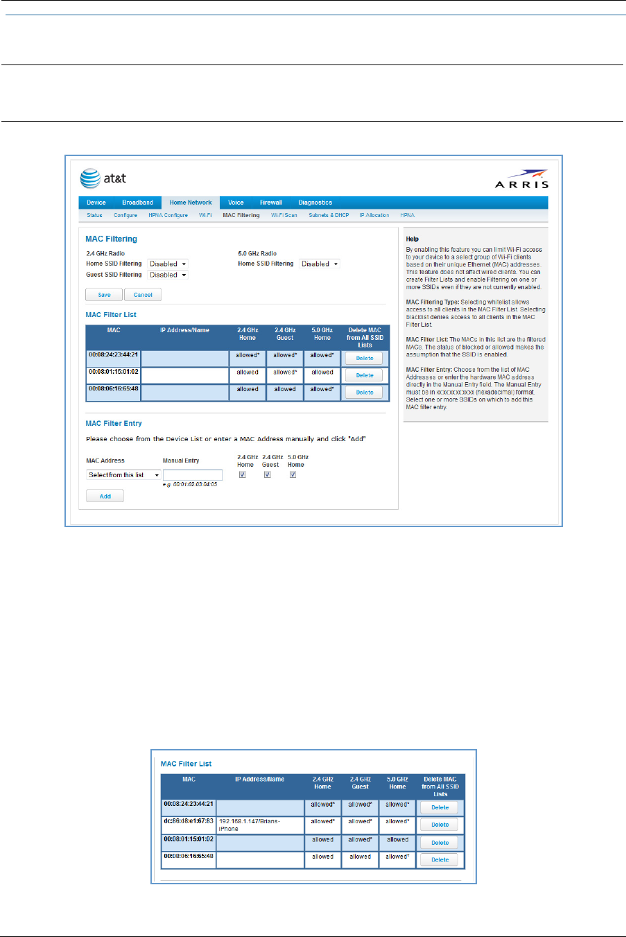
Link: MAC Filtering
When you click the MAC Filtering link the MAC Filtering page appears.
MAC filtering allows you to specify which client PCs are allowed to join the wireless LAN by unique hardware
(MAC) address.
To enable this feature, select Blacklist or Whitelist from the MAC Filtering Type menu. Blacklist means that
only MAC addresses you specify will be denied access; Whitelist means that only MAC addresses you specify
will be allowed access.
You add wireless clients that you want to whitelist or blacklist for your wireless LAN by selecting them from
the MAC Address drop-down list or by entering the MAC addresses in the Manual Entry field provided.
Click the Add button.
Your entries will be added to a list of clients that will be either authorized (whitelisted) or disallowed
(blacklisted) depending on your selection.
Click the Save button.
NOTE:
5.0 Ghz Radio selection is reserved for future use.
Administrator’s Handbook
48
You can add or delete any of your entries later by returning to this page.
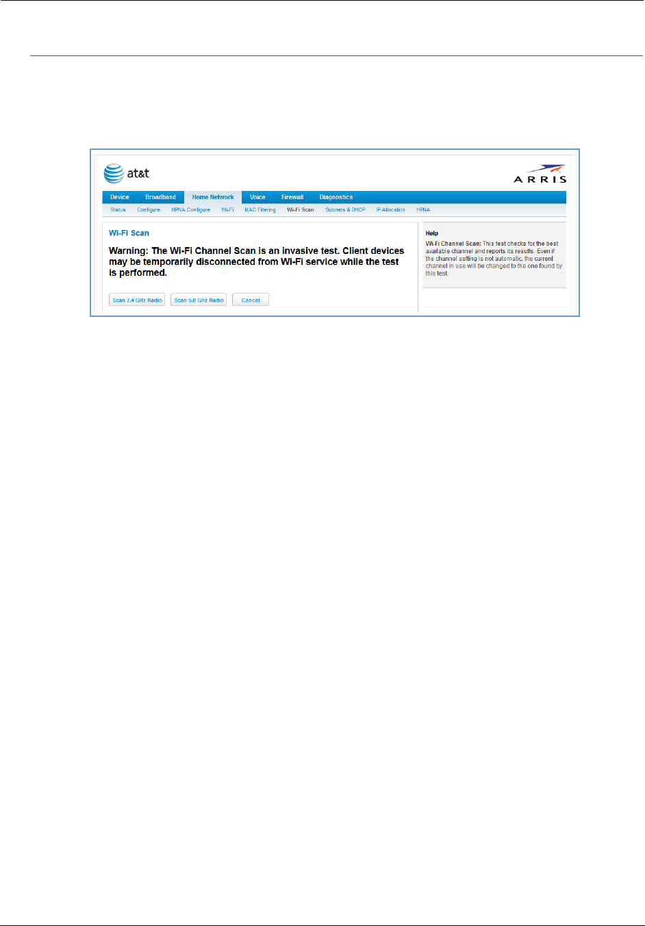
Link: WiFi Scan
Your device automatically checks for the best channel to broadcast wireless services. However, in some cases it
may be useful to switch to a different channel (1 through 11, for North America) on which the network will
broadcast.
The scan covers a frequency range within the 2.4 Ghz or 5.0 Ghz band. Channel selection depends on
government regulated radio frequencies that vary from region to region. Channel selection can have a
significant impact on performance, depending on other wireless activity close to this device. You need not
select a channel at any of the computers on your wireless network. They will automatically scan available
channels seeking a wireless device broadcasting on the SSID for which they are configured.
This scan will disconnect any wireless client devices from the wireless network.
If you want to scan for a different channel on which the device will broadcast, click the Continue button.
49
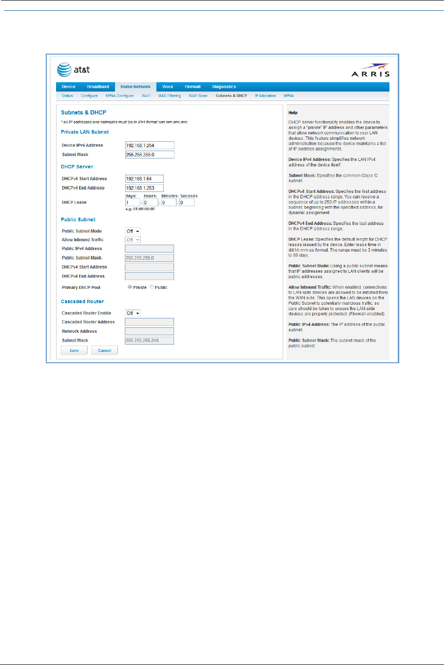
Link: Subnets & DHCP
When you click the Subnets & DHCP link, the Subnets & DHCP page appears.
The server configuration determines the functionality of your DHCP settings. This functionality enables the
NVG599 to assign your LAN computer(s) a “private” IP address and other parameters that allow network
communication. This feature simplifies network administration because the NVG599 maintains a list of IP
address assignments. Additional computers can be added to your LAN without the need to configure an IP
address. This is the default mode for your NVG599 device.
Private LAN Subnet
Device IPv4 Address: The IP address of your device as seen from the LAN.
Subnet Mask: Subnet mask of your LAN.
DHCP
DHCPv4 Start Address: First IP address in the range being served to your LAN by the NVG599 DHCP server.
DHCPv4 End Address: Last IP address in the range being served to your LAN by the NVG599 DHCP server.
DHCP Lease: Specifies the default length for DHCP leases issued by the router. Enter lease time in
dd:hh:mm:ss (days/hours/minutes/seconds) format.
Public Subnet
Public Subnet Enable: If you select On from the drop-down menu, you can enable a second subnet to dis-
tribute public addresses to DHCP clients; this means that IP addresses assigned to LAN clients will be public
addresses.
Public IPv4 Address: The IP address of your NVG599 device as seen from the WAN.
Public Subnet Mask: Public subnet mask.
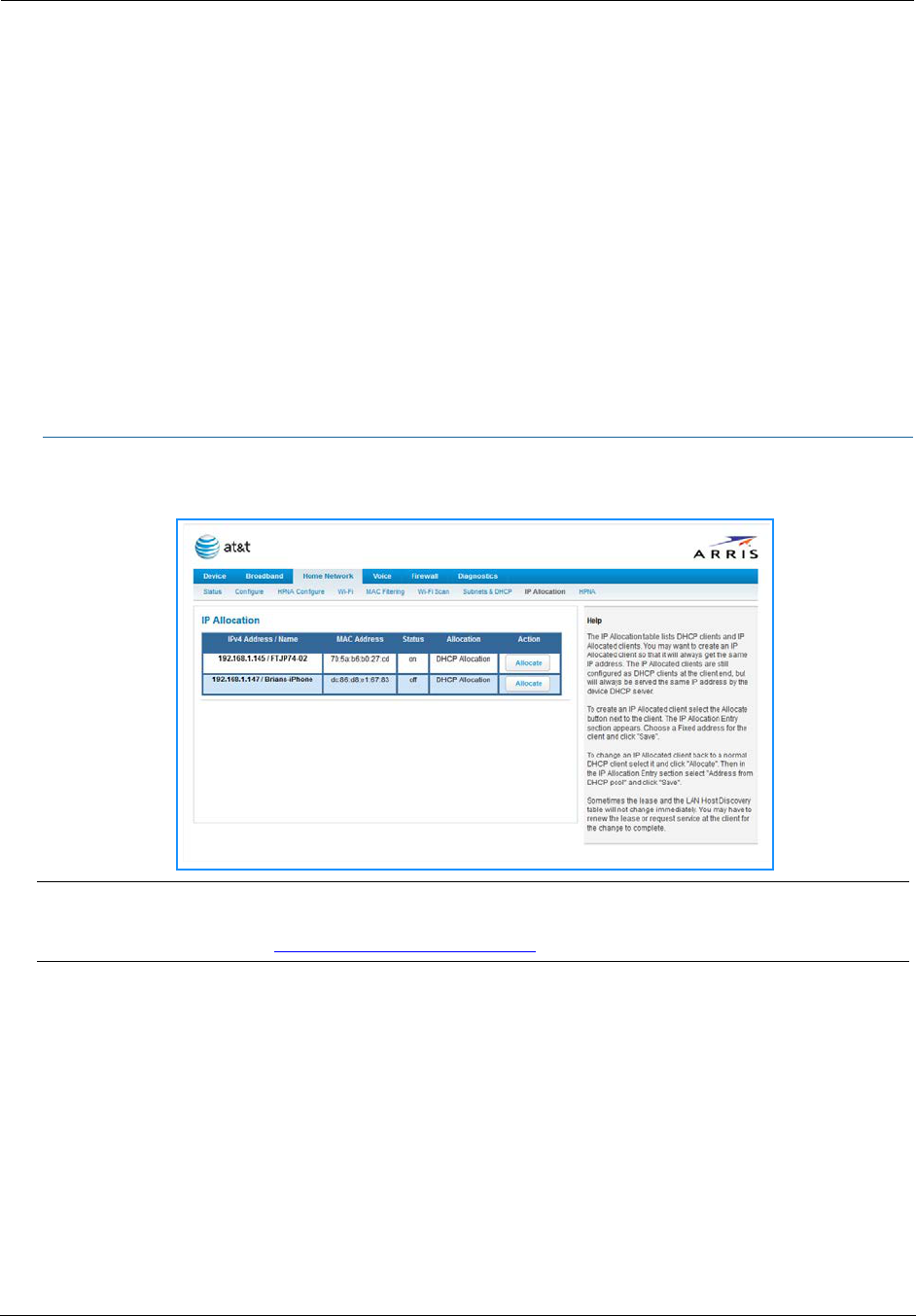
Administrator’s Handbook
50
DHCPv4 Start Address: First IP address in the range being served from a DHCP public pool.
DHCPv4 End Address: Last IP address in the range being served from a DHCP public pool.
Primary DHCP Pool: Choose the source of the DHCP pool IP address assignment by selecting either Private
(local to your LAN) or Public (assigned remotely).
Cascaded Router
Cascaded Router Enable: If you have another router behind this device, choose On from the drop-down
menu.
Cascaded Router Address: If you chose On from the drop-down menu, enter the IP address of the router
you are using behind this device in the LAN private IP subnet range.
Network Address: If you chose On from the drop-down menu, enter the Network Address that defines the
range of IP addresses available to clients of the router you are using behind this device.
Subnet Mask: If you chose On from the drop-down menu, enter the subnet mask for the network address
that defines the range of IP addresses available to clients of the router you are using behind this device.
If you make any changes here, click the Save button, and if prompted, restart the NVG599 device.
Link: IP Allocation
When you click the IP Allocation link, the IP Allocation page appears.
The IP Allocation page lets you set aside or assign IP addresses to client devices on your network. With IP
allocation, you can configure known devices to either use DHCP for dynamic IP address assignment, or set
aside a specific IP address for a client device. When IP allocation is enabled for a client, that device is assigned
a pre-determined IP address by the DHCP server of the NVG599. IP allocation lets you set up client devices as
common DHCP systems, but ensures that they always receive the same IP address from the gateway.
The IP Allocation table shows a list of all identified and active client devices the NVG599 is serving.
To change the allocation method used by a client:
1. Locate the client in the IP Allocation table. The client may be identified by the Name value (in the IPv4
Address/Name column) or the device MAC address.
2. Click the Allocate button associated with the client entry.
NOTE:
IP Allocation functions require you to enter your NVG599 Gateway’s access code. Information on the device
code is provided in “Device Access Code” on page 24