ARRIS 2108-N9 Gigabit Ethernet Router with HPNA and 802.11n User Manual 2108 N D9
ARRIS Group, Inc. Gigabit Ethernet Router with HPNA and 802.11n 2108 N D9
UserManual.wiki
>
ARRIS
>
2108 N9 User Manual
User manual
Navigation menu
Upload a User Manual
Namespaces
Wiki Guide
HTML
PDF
Info
Views
User Manual
Discussion / Help
Navigation

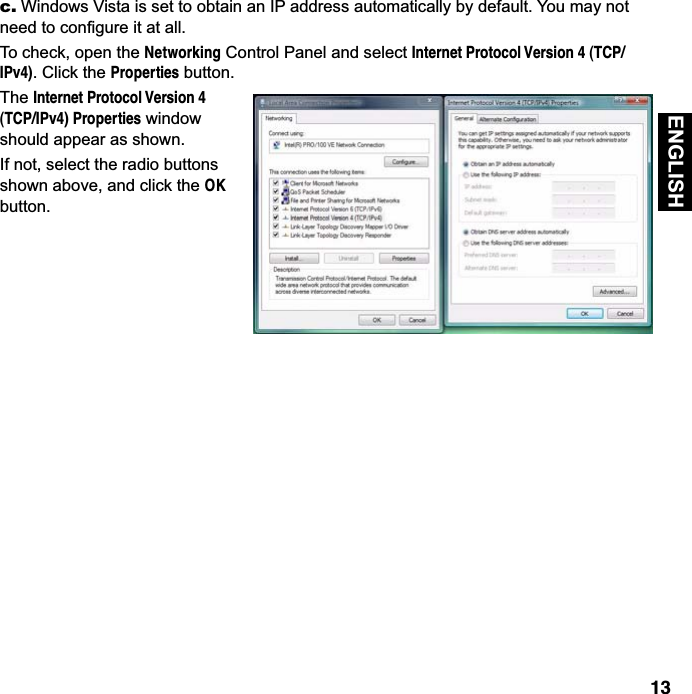
![12 ENGLISH Your Gateway serves Dynamically-assigned IP addresses by default. Be sure to configure each computer connected to your Gateway to accept a Dynamically-assigned IP address, commonly referred to as DHCP. Microsoft Windows: Step 1. Navigate to the TCP/IP Properties Control Panel. a. Windows 98, 2000, and ME versions follow a path like this: Start menu -> Settings -> Control Panel -> Network (or Network and Dial-up Connections -> Local Area Connection -> Properties ) -> TCP/IP [your_network_card] or Internet Protocol [TCP/IP] -> Properties b. Windows XP follows a path like this:Start menu -> Control Panel -> Network and Internet Connections -> Network Connections -> Local Area Connection -> Properties -> Internet Protocol [TCP/IP] -> PropertiesStep 2. Select Obtain an IP address automatically.Step 3. Select Obtain DNS server address automatically, if available.Step 4. Remove any previously configured Gateways, if available.Step 5. OK the settings. Restart if prompted.Client Configuration](https://usermanual.wiki/ARRIS/2108-N9/User-Guide-1308765-Page-12.png)

![The user manual of transmitter devices equipped with detachable antennas shall contain the following information in a conspicuous location:This device has been designed to operate with the antennas listed below, and having a maximum gain of [1.8] dB. Antennas not included in this list or having a gain greater than [1.8] dB are strictly prohibited for use with this device. The required antenna impedance is [50] ohms.To reduce potential radio interference to other users, the antenna type and its gain should be so chosen that the equivalent isotropically radiated power (e.i.r.p.) is not more than that permitted for successful communication.IEEE 802.11b or 802.11g operation of this product in the Canada is firmware-limited to channels 1 through 11.FCC RF Radiation Exposure Statement:1. This Transmitter must not be co-located or operating in conjunction with any other antenna or transmitter.2. This equipment complies with FCC RF radiation exposure limits set forth for an uncontrolled environment. This equipment should be installed and operated with a minimum distance of 20 centimeters between the adiator and your body.This equipment complies with IC RF radiation exposure limits set forth for an uncontrolled environment. This equipment should be installed and operated with a minimum distance of 20 centimeters between the radiator and your body.](https://usermanual.wiki/ARRIS/2108-N9/User-Guide-1308765-Page-18.png)