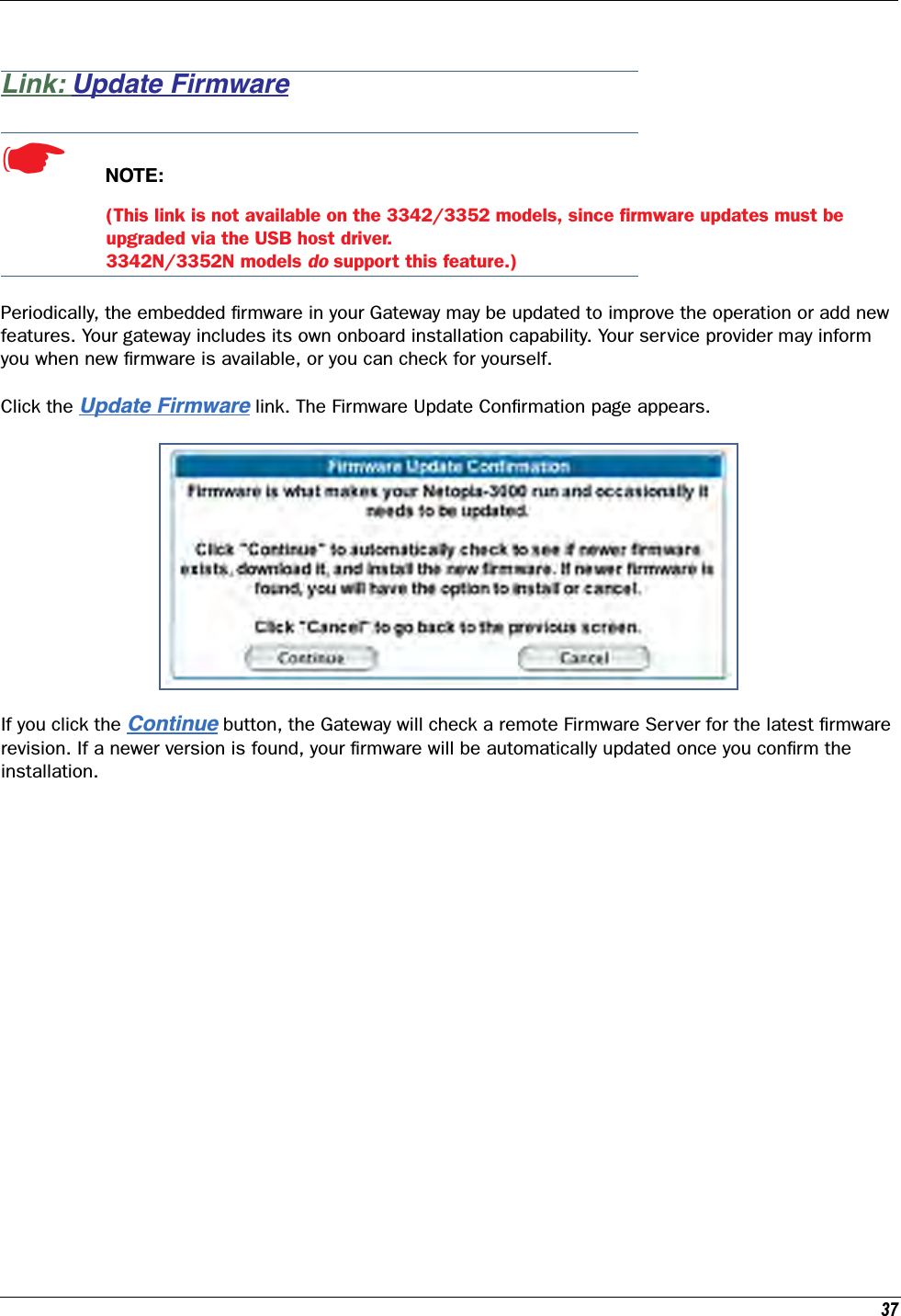
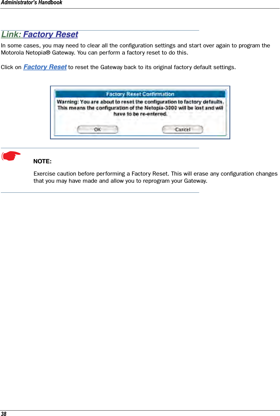
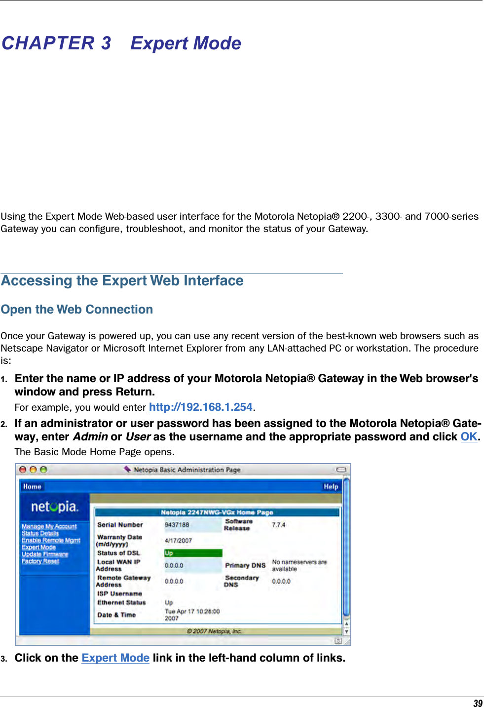
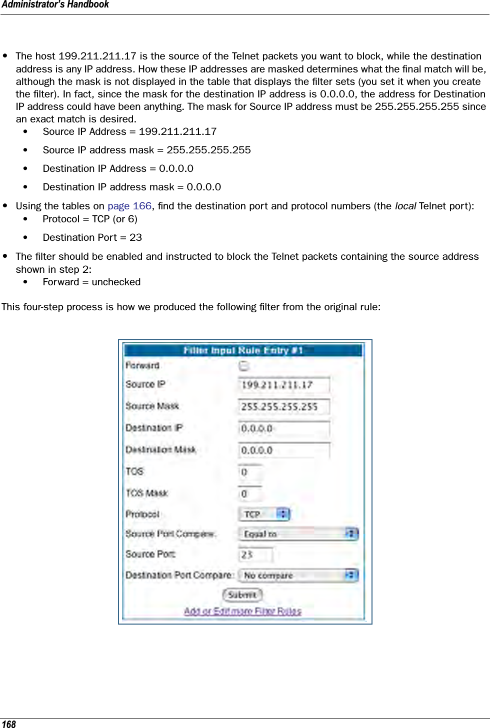
ARRIS 224742 ADSL2+ 802.11b/g Ethernet Modem User Manual Administrator s Handbook V7 7 4
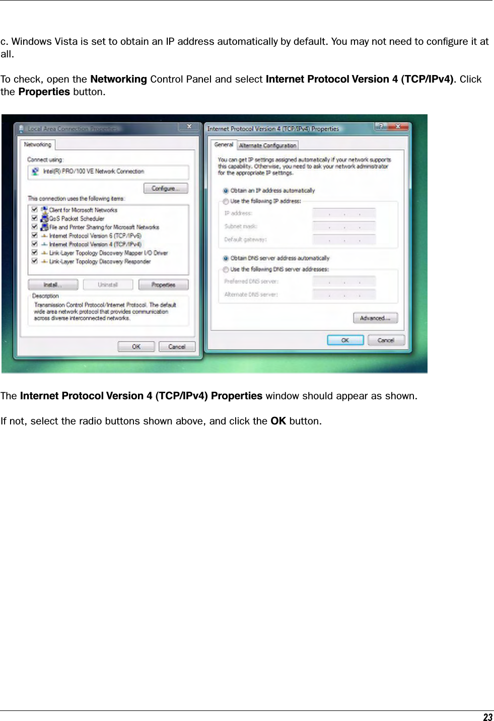
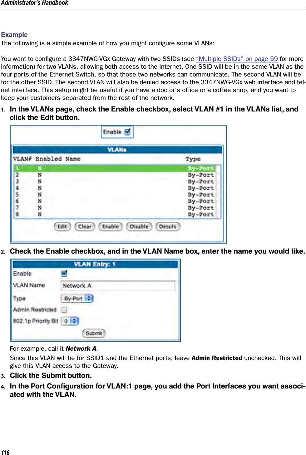
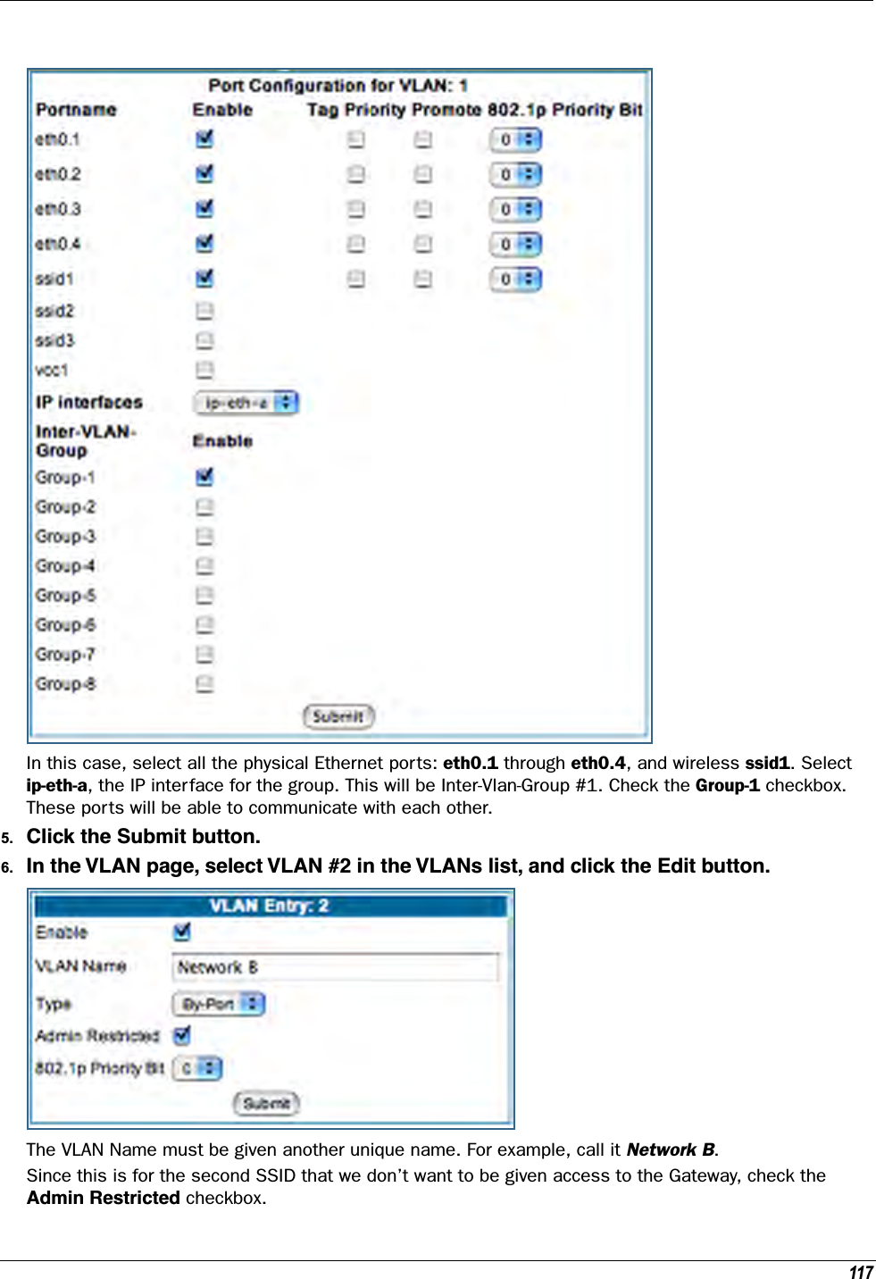
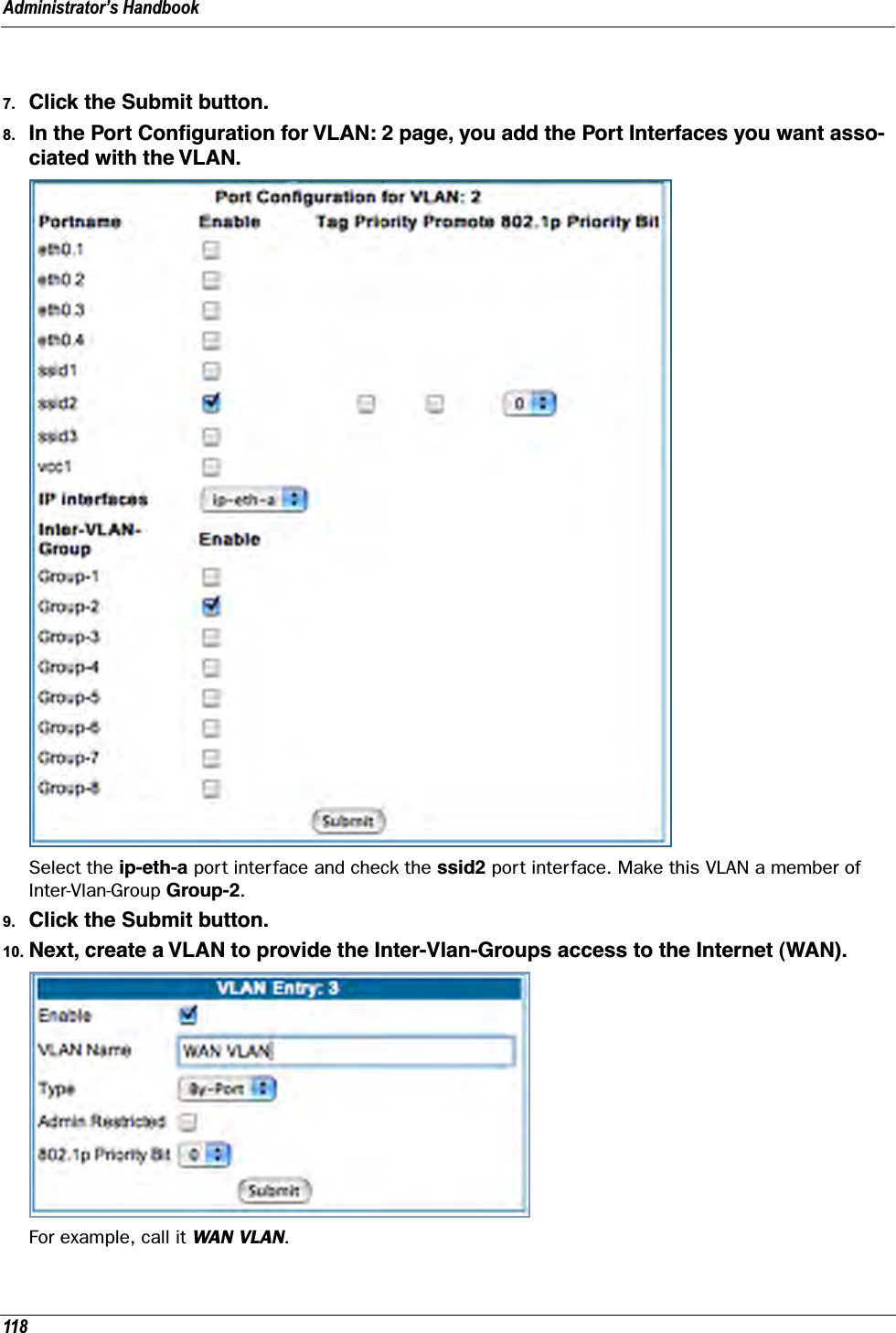
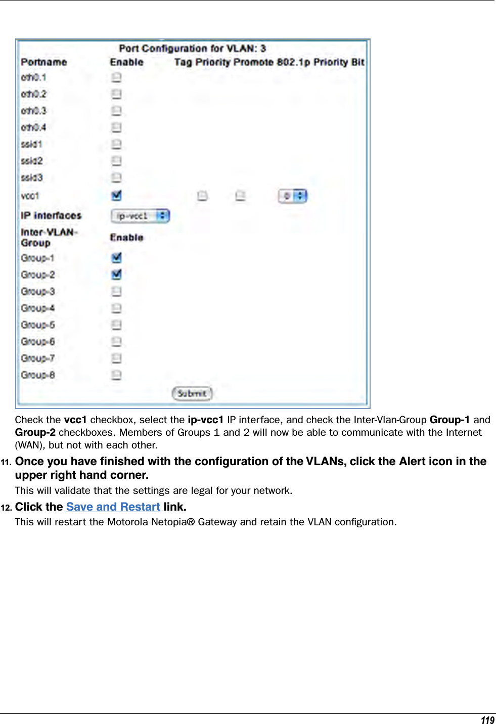
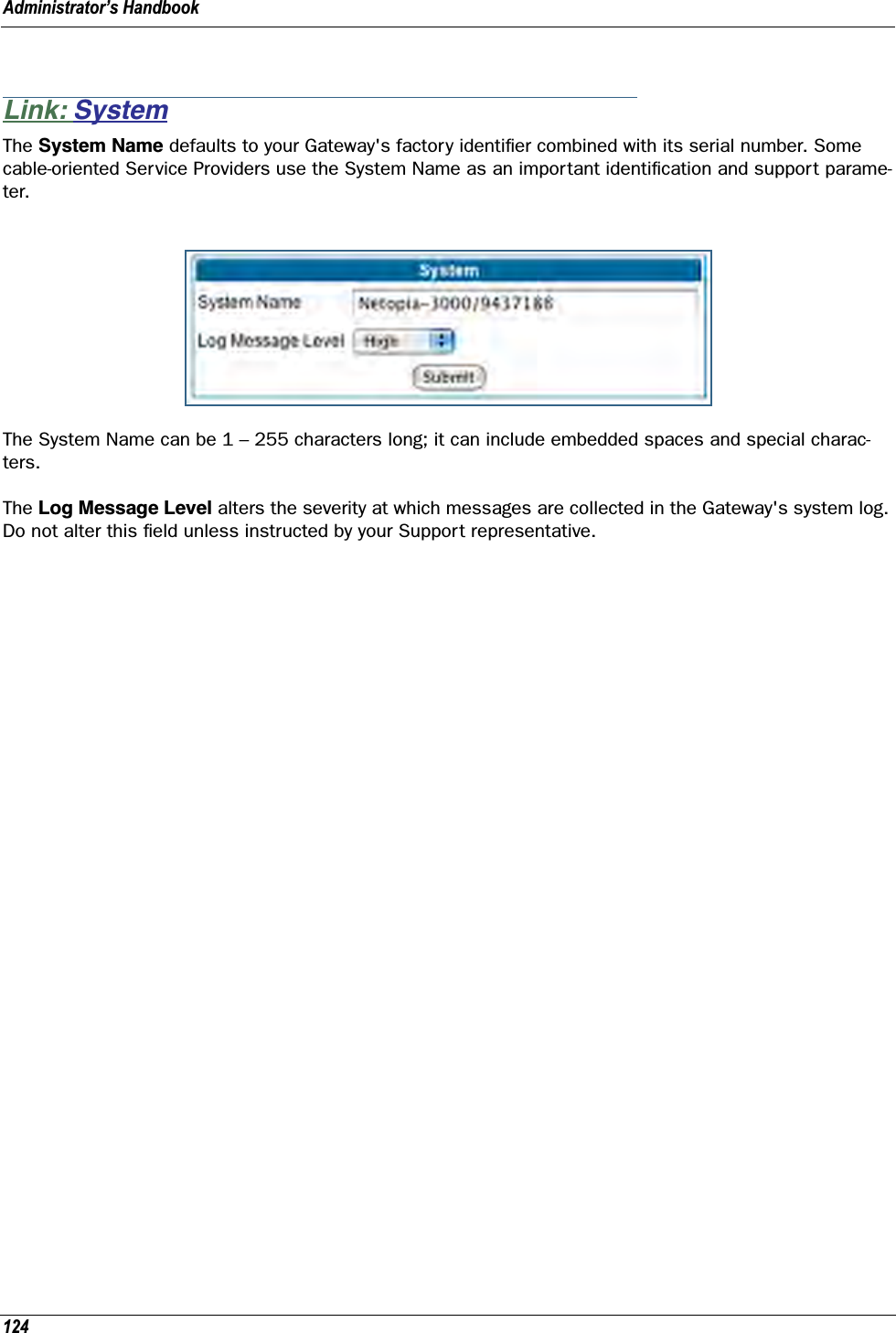
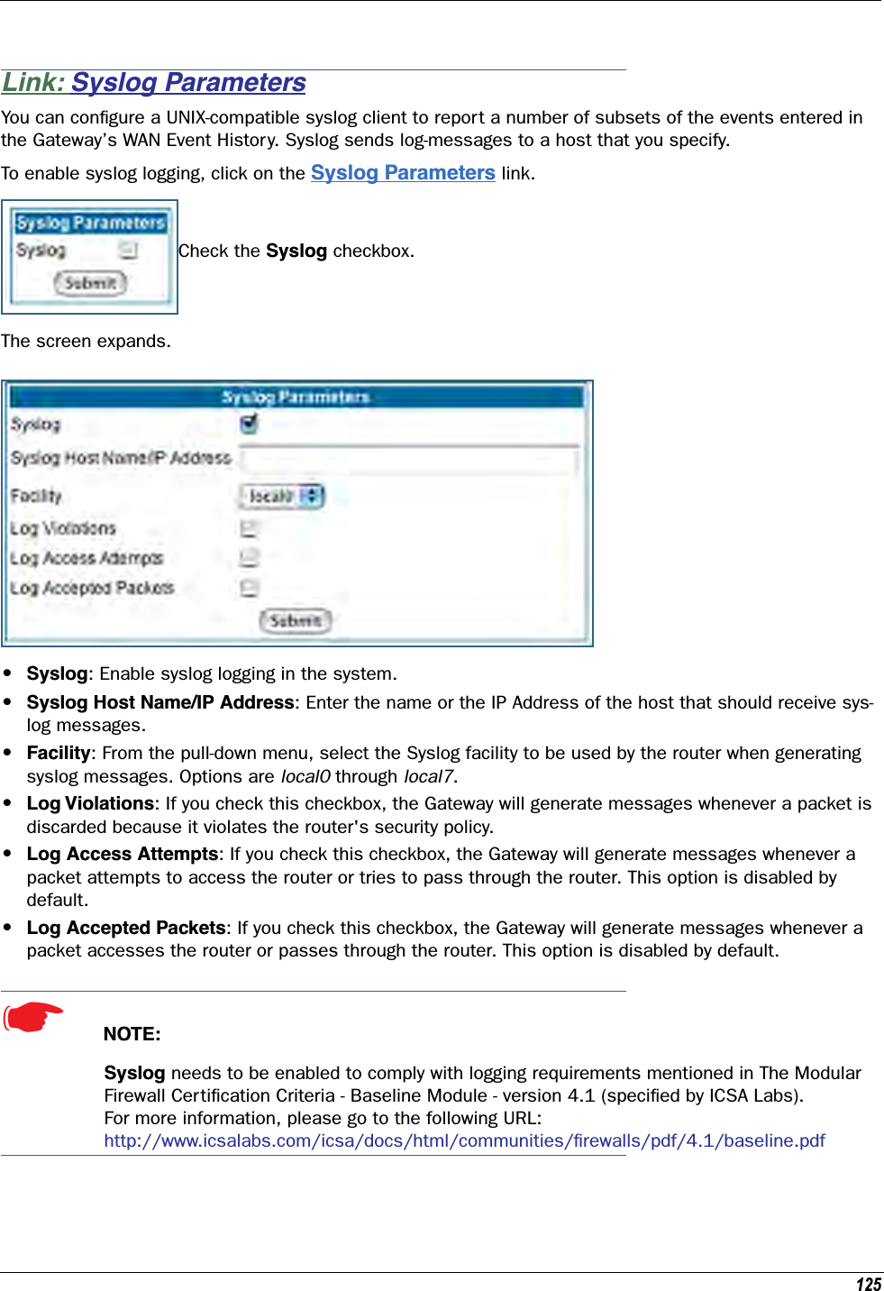
ARRIS Group, Inc. ADSL2+ 802.11b/g Ethernet Modem Administrator s Handbook V7 7 4
ARRIS >
Contents
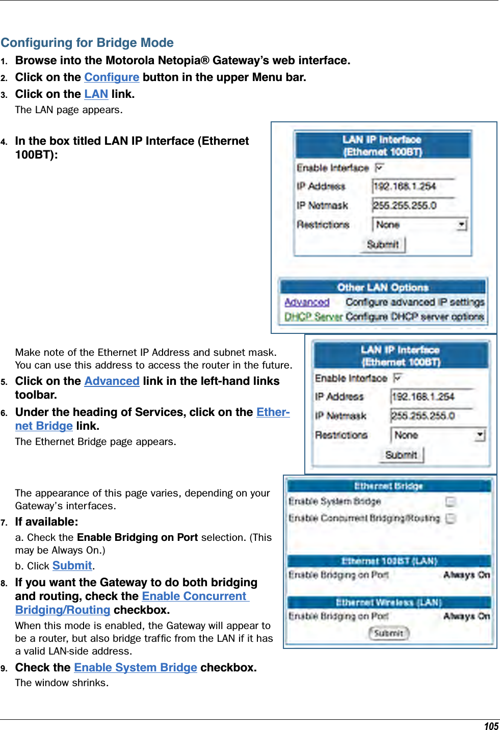
- 1. User Manual Part One
- 2. User Manual Part Two
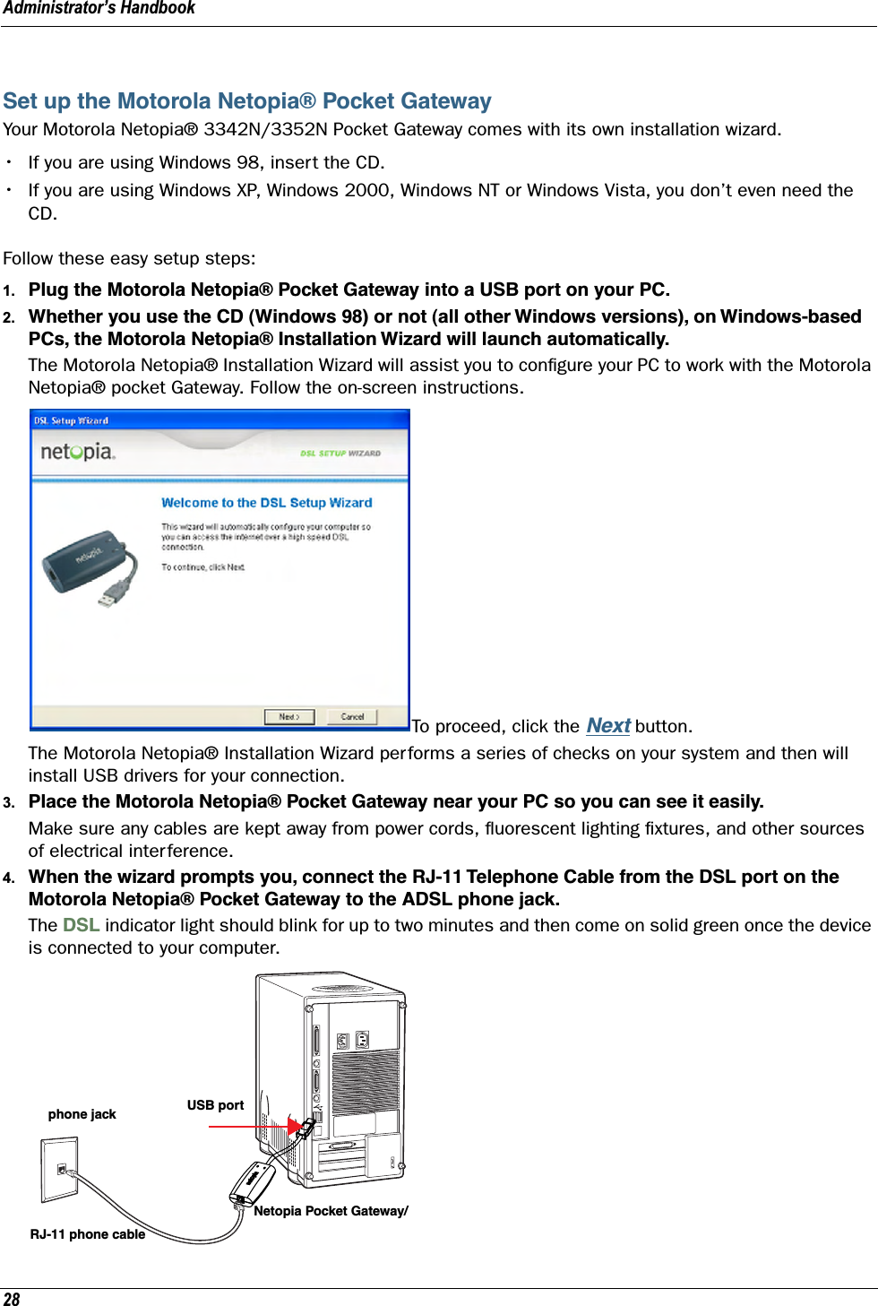
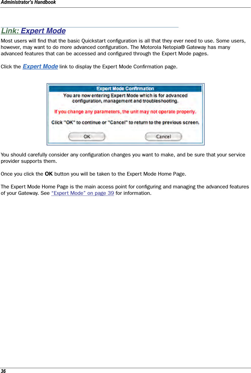
User Manual Part One
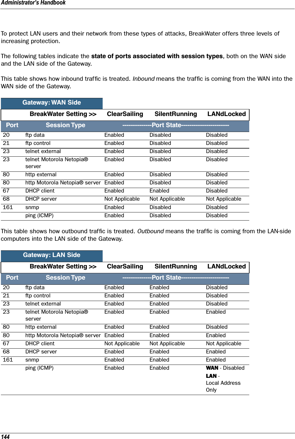
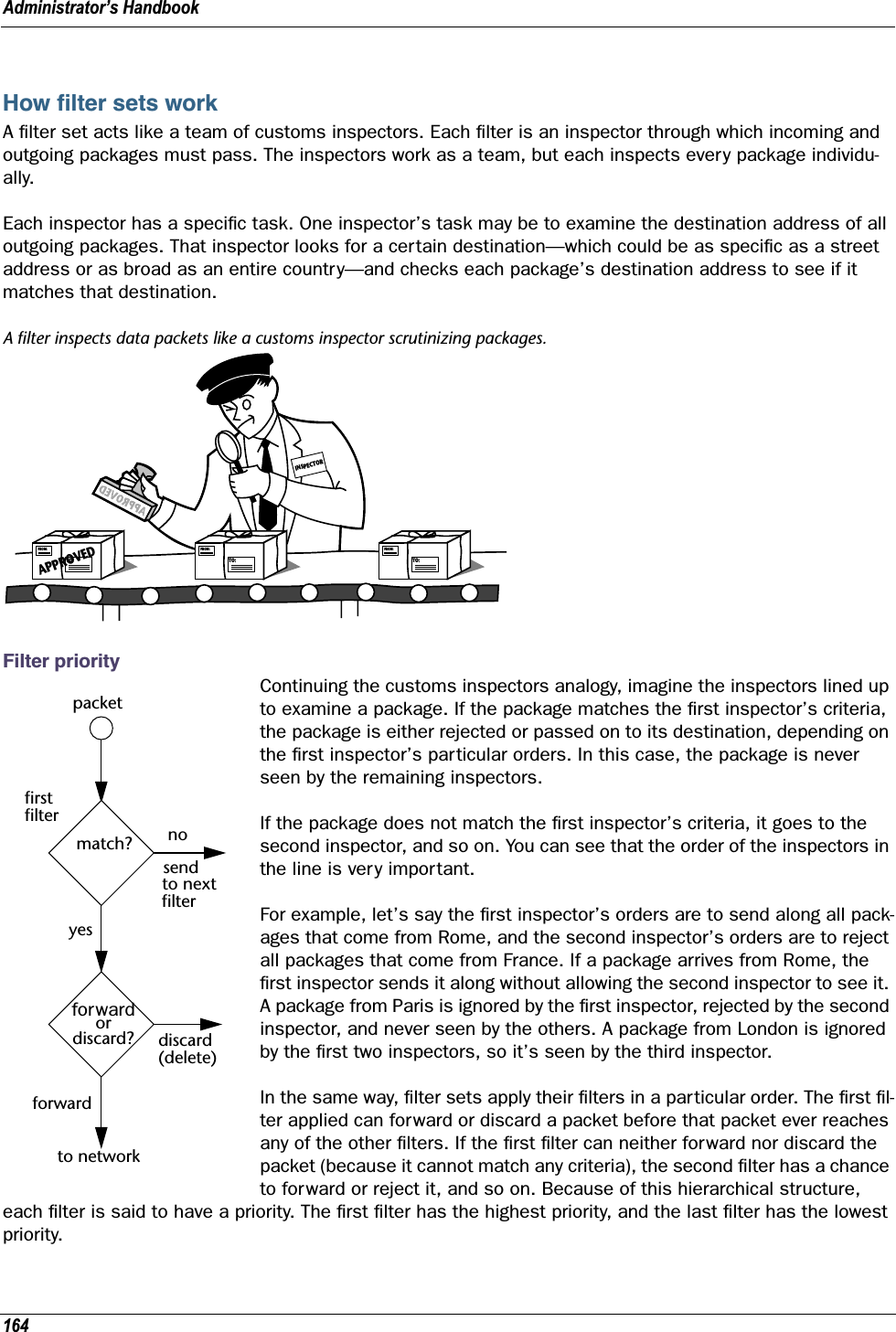
![Copyright remains Eric Young's, and as such any Copyright notices in the code are not to be removed. If this package is used in a product, Eric Young should be given attribution as the author of the parts of the library used. This can be in the form of a textual message at program startup or in documentation (online or textual) provided with the package.Redistribution and use in source and binary forms, with or without modification, are permitted provided that the following conditions are met: 1. Redistributions of source code must retain the copyright notice, this list of conditions and the following disclaimer. 2. Redistributions in binary form must reproduce the above copyright notice, this list of conditions and the following disclaimer in the documentation and/or other materials provided with the distribution. 3. All advertising materials mentioning features or use of this software must display the following acknowledgement: “This product includes cryptographic software written by Eric Young (eay@cryptsoft.com)” The word 'cryptographic' can be left out if the routines from the library being used are not cryptographic related :-). 4. If you include any Windows specific code (or a derivative thereof) from the apps directory (application code) you must include an acknowledgement: “This product includes software written by Tim Hudson (tjh@cryptsoft.com)”THIS SOFTWARE IS PROVIDED BY ERIC YOUNG ``AS IS'' AND ANY EXPRESS OR IMPLIED WARRANTIES, INCLUDING, BUT NOT LIMITED TO, THE IMPLIED WARRANTIES OF MERCHANTABILITY AND FITNESS FOR A PARTICULAR PURPOSE ARE DISCLAIMED. IN NO EVENT SHALL THE AUTHOR OR CONTRIBUTORS BE LIABLE FOR ANY DIRECT, INDIRECT, INCIDENTAL, SPECIAL, EXEMPLARY, OR CONSEQUENTIAL DAMAGES (INCLUDING, BUT NOT LIMITED TO, PROCUREMENT OF SUBSTITUTE GOODS OR SERVICES; LOSS OF USE, DATA, OR PROFITS; OR BUSINESS INTERRUPTION) HOWEVER CAUSED AND ON ANY THEORY OF LIABILITY, WHETHER IN CONTRACT, STRICT LIABILITY, OR TORT (INCLUDING NEGLIGENCE OR OTHERWISE) ARISING IN ANY WAY OUT OF THE USE OF THIS SOFTWARE, EVEN IF ADVISED OF THE POSSIBILITY OF SUCH DAMAGE.The licence and distribution terms for any publicly available version or derivative of this code cannot be changed. i.e. this code cannot simply be copied and put under another distribution licence [including the GNU Public Licence.] Portions of this software are based in part on the work of the following: Copyright (C) 1995, 1996, 1997, and 1998 WIDE Project. All rights reserved.Redistribution and use in source and binary forms, with or without modification, are permitted provided that the following conditions are met: 1. Redistributions of source code must retain the above copyright notice, this list of conditions and the following disclaimer. 2. Redistributions in binary form must reproduce the above copyright notice, this list of conditions and the following disclaimer in the documentation and/or other materials provided with the distribution. 3. Neither the name of the project nor the names of its contributors may be used to endorse or promote products derived from this software without specific prior written permission.THIS SOFTWARE IS PROVIDED BY THE PROJECT AND CONTRIBUTORS ``AS IS'' AND ANY EXPRESS OR IMPLIED WARRANTIES, INCLUDING, BUT NOT LIMITED TO, THE IMPLIED WARRANTIES OF MERCHANTABILITY AND FITNESS FOR A PARTICULAR PURPOSE ARE DISCLAIMED. IN NO EVENT SHALL THE PROJECT OR CONTRIBUTORS BE LIABLE FOR ANY DIRECT, INDIRECT, INCIDENTAL, SPECIAL, EXEMPLARY, OR CONSEQUENTIAL DAMAGES (INCLUDING, BUT NOT LIMITED TO, PROCUREMENT OF SUBSTITUTE GOODS OR SERVICES; LOSS OF USE, DATA, OR PROFITS; OR BUSINESS INTERRUPTION) HOWEVER CAUSED AND ON ANY THEORY OF LIABILITY, WHETHER IN CONTRACT, STRICT LIABILITY, OR TORT (INCLUDING NEGLIGENCE OR OTHERWISE) ARISING IN ANY WAY OUT OF THE USE OF THIS SOFTWARE, EVEN IF ADVISED OF THE POSSIBILITY OF SUCH DAMAGE. Portions of this software are based in part on the work of the following: Copyright (C) 1990, RSA Data Security, Inc. All rights reserved.<<RSA Data Security, Inc. MD5 Message-Digest Algorithm>>License to copy and use this software is granted provided that it is identified as the “RSA Data Security, Inc. MD5 Message Digest Algorithm” in all material mentioning or referencing this software or this function.License is also granted to make and use derivative works provided that such works are identified as “derived from the RSA Data Security, Inc. MD5 Message-Digest Algorithm” in all material mentioning or referencing the derived work.<<RSA Data Security, Inc. MD4 Message-Digest Algorithm>>License to copy and use this software is granted provided that it is identified as the “RSA Data Security, Inc. MD4 Message Digest Algorithm” in all material mentioning or referencing this software or this function.License is also granted to make and use derivative works provided that such works are identified as “derived from the RSA Data Security, Inc. MD4 Message-Digest Algorithm” in all material mentioning or referencing the derived work.](https://usermanual.wiki/ARRIS/224742.User-Manual-Part-One/User-Guide-899049-Page-3.png)
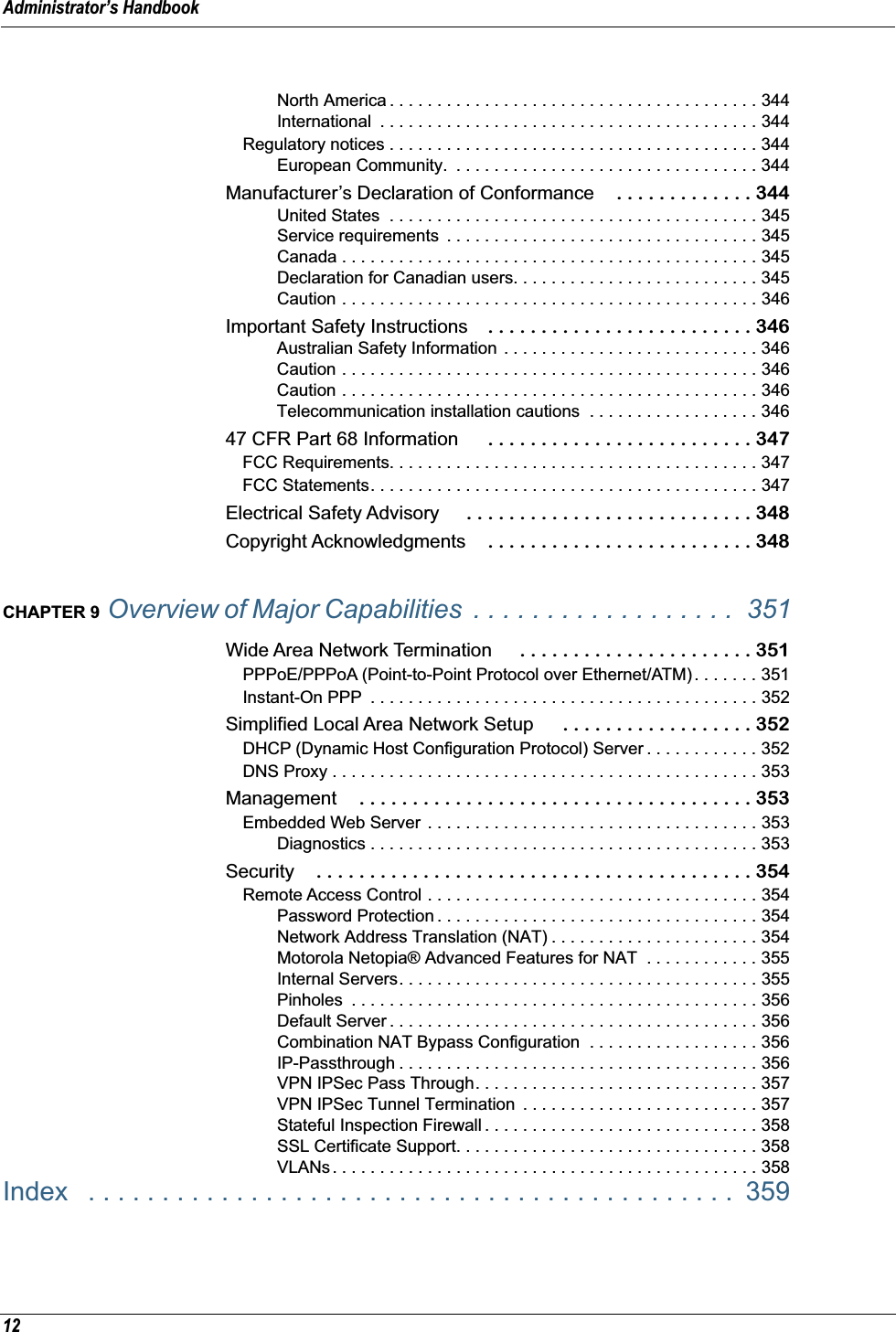
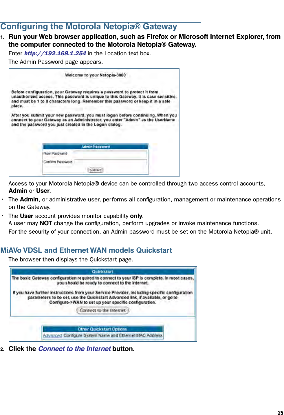
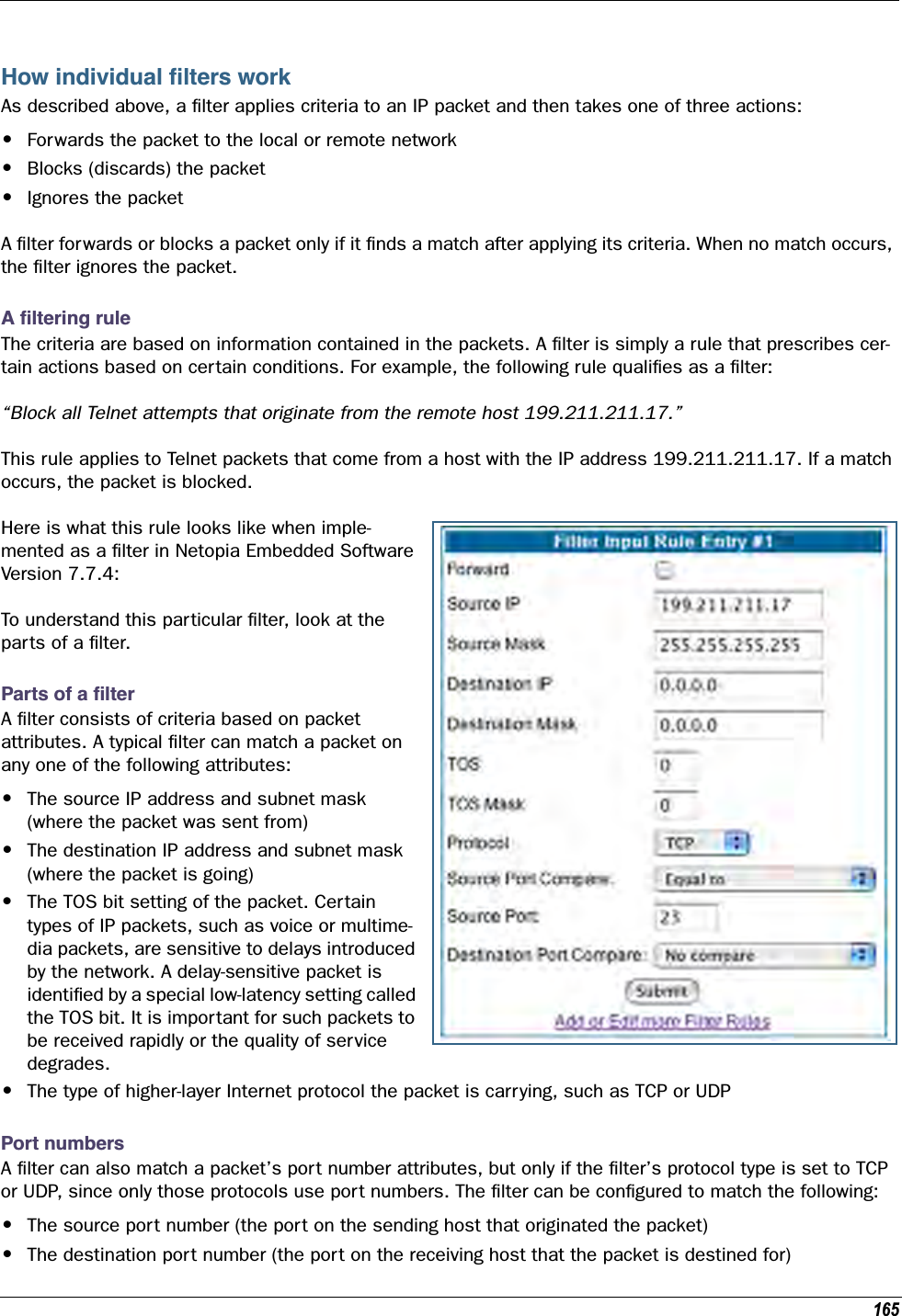
![13 CHAPTER 1 Introduction What’s New in 7.7.4 New in Motorola Netopia® Embedded Software Version 7.7.4 are the following features: • Internet Group Management Protocol (IGMP) Version 3 support. See “IGMP (Internet Group Management Protocol)” on page 100. • TR-101 Support:• Concurrent support for PPPoE and IPoE connections on the WAN. See “WAN” on page 67.• Multiple LAN IP Subnet support. See “LAN” on page 49.• Additional DHCP range support. These ranges are associated with the additional LAN subnets on a 1-to-1 basis.• DHCP option filtering support. Allows DHCP option data to be used to determine the desired DHCP address range. See “DHCP Option Filtering” on page 252.• Support for additional WAN settings to control multicast forwarding as well as if 0.0.0.0 is used as the source address for IGMP packets. See “Advanced:” on page 69.• Support for “unnumbered” interfaces. For IP interfaces, this allows the address to be set to 0 and the DHCP client also to be disabled. See page 71. • PPPoE/DHCP Autosensing. See “WAN” on page 67. • Wireless Multimedia Mode (WMM) support. See “WiFi Multimedia” on page 62. • Firewall: ClearSailing is automatically enabled on all 2200-Series ADSL2+ platforms. (Explicit excep-tions: bonded and VDSL2, 3341, and 3387WG.) See “Firewall” on page 142. • TR-069 Remote device management is automatically enabled by default for 2200-Series Gateways. (Explicit exceptions: bonded and VDSL2, 3341, 3387WG). See “TR-069” on page 322. • Voice-over-IP (VoIP) Support using Session Initiation Protocol (SIP) for supported models. See “VoIP” on page 120 and VoIP CLI “VoIP settings” on page 316. • Support of VLAN ID 0 on the Ethernet WAN and support for setting p-bits on a segment/port basis; inter-VLAN groups. See “VLAN” on page 107 and CLI “VLAN Settings” on page 311. • Backup IP Gateway Support. See “Backup” on page 133 and CLI “Backup IP Gateway Settings” on page 323.Corresponding commands have been added to the Command Line Interface (CLI). See “Command Line Interface” on page 223. • Reset WAN port and wireless counter and CLI command to display individual Ethernet port statistics. See “reset enet [ all ]” on page 231 and “show enet [ all ]” on page 233. •CLI for Motorola Netopia® ATA Remote Management. See “Remote ATA Configuration Commands” on page 243.](https://usermanual.wiki/ARRIS/224742.User-Manual-Part-One/User-Guide-899049-Page-13.png)
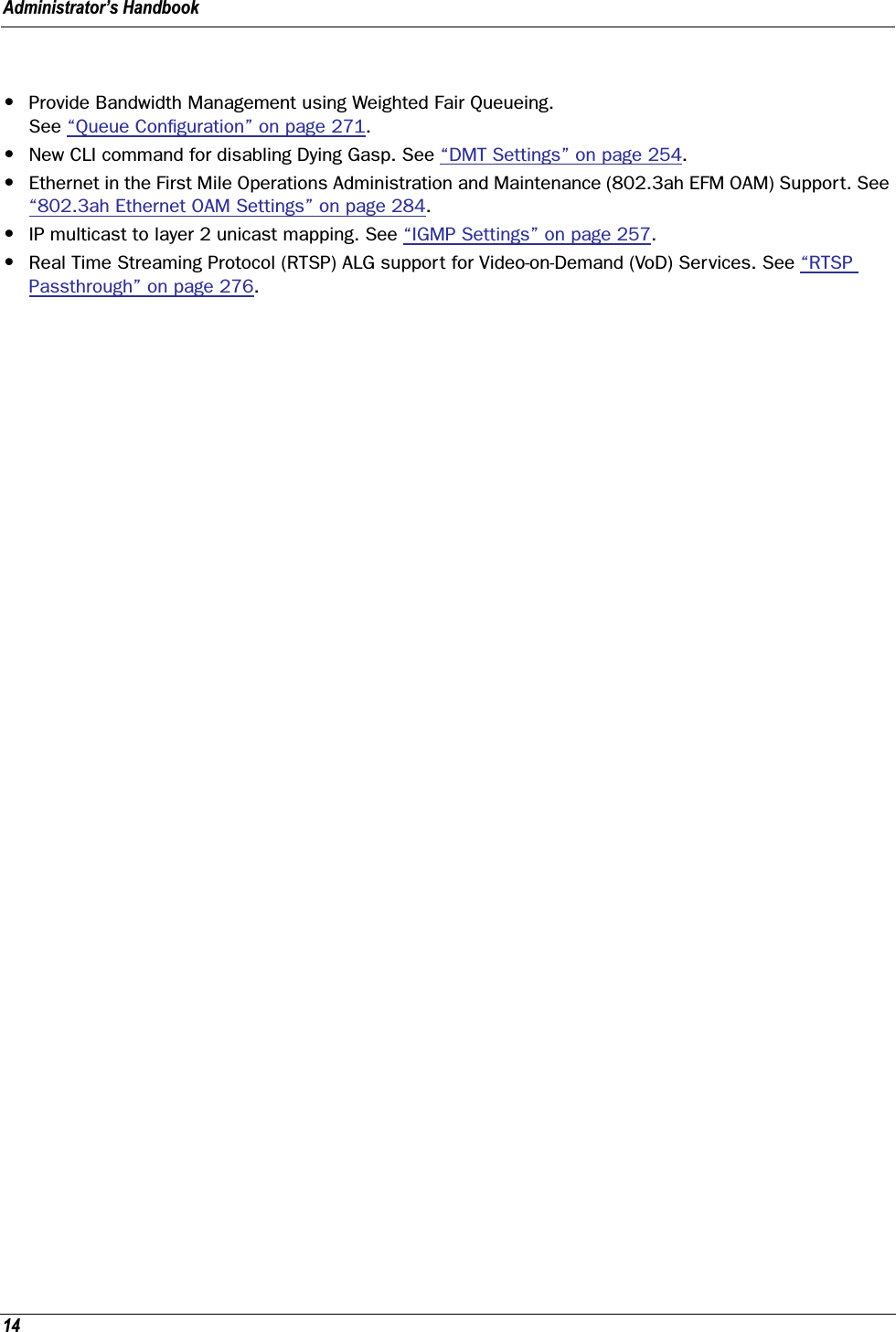
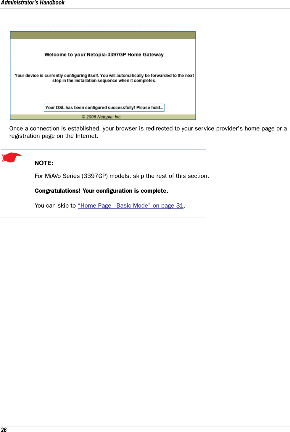
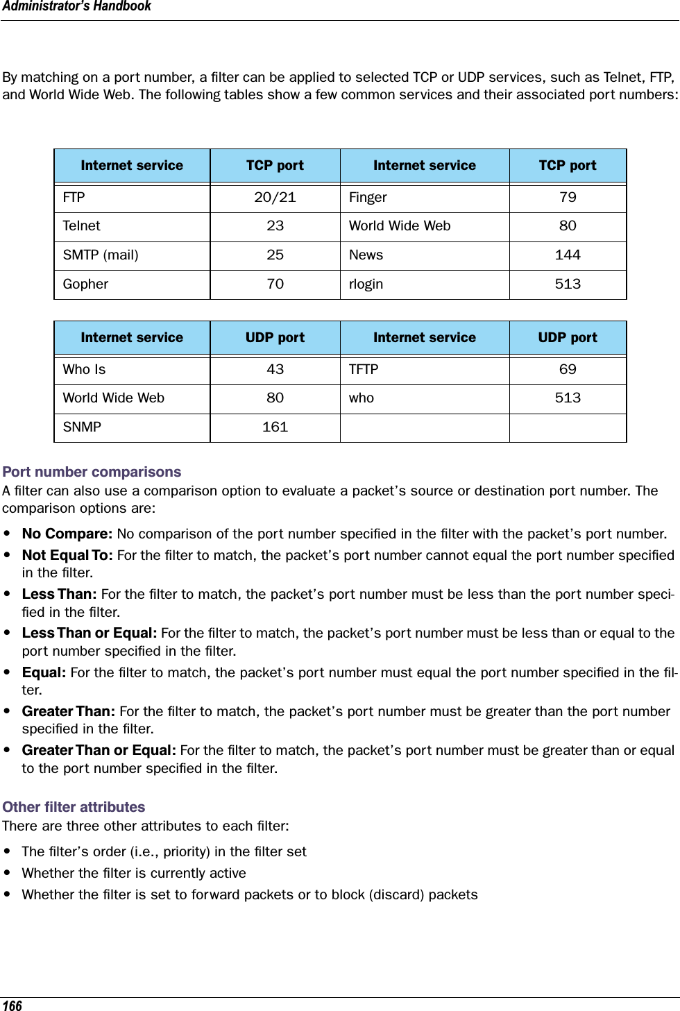
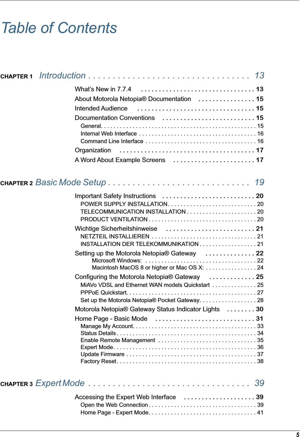
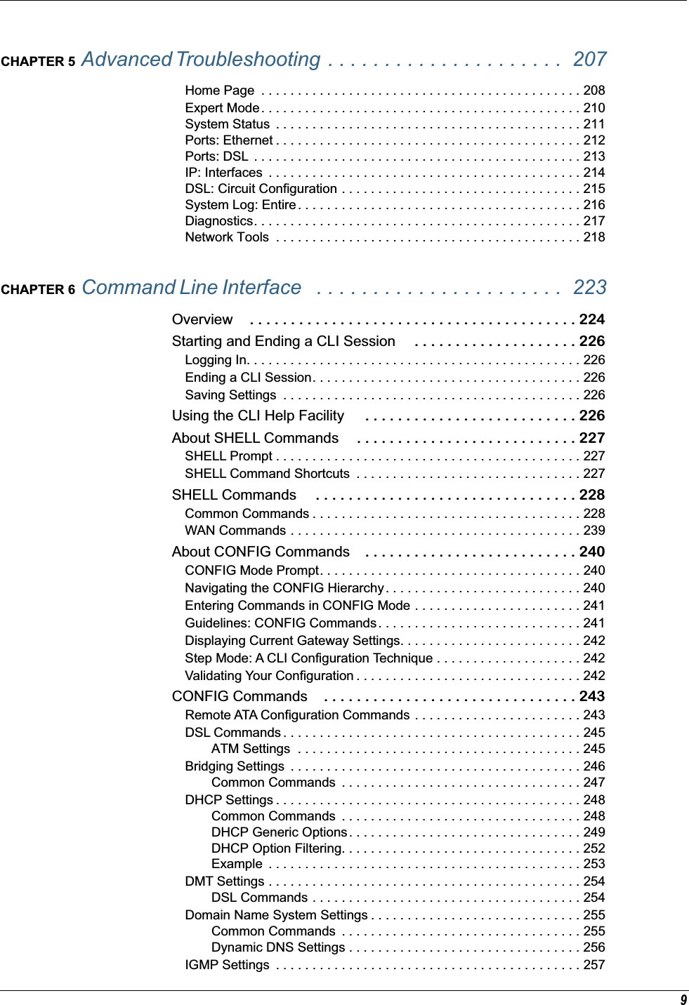
![Administrator’s Handbook16Internal Web InterfaceCommand Line InterfaceSyntax conventions for the Netopia Gateway command line interface are as follows:terminal Computer display textbold terminal User-entered textItalic Italic type indicates the complete titles of manuals.Convention (Graphics) DescriptionDenotes an “excerpt” from a Web page or the visual truncation of a Web pageDenotes an area of emphasis on a Web pageConvention Descriptionstraight ([ ]) brackets in cmd line Optional command arguments curly ({ }) brackets, with values sep-arated with vertical bars (|).Alternative values for an argument are presented in curly ({ }) brackets, with values separated with vertical bars (|).bold terminal type faceUser-entered textitalic terminal type faceVariables for which you supply your own valuesblue rectangle or linesolid rounded rectangle with an arrow](https://usermanual.wiki/ARRIS/224742.User-Manual-Part-One/User-Guide-899049-Page-16.png)
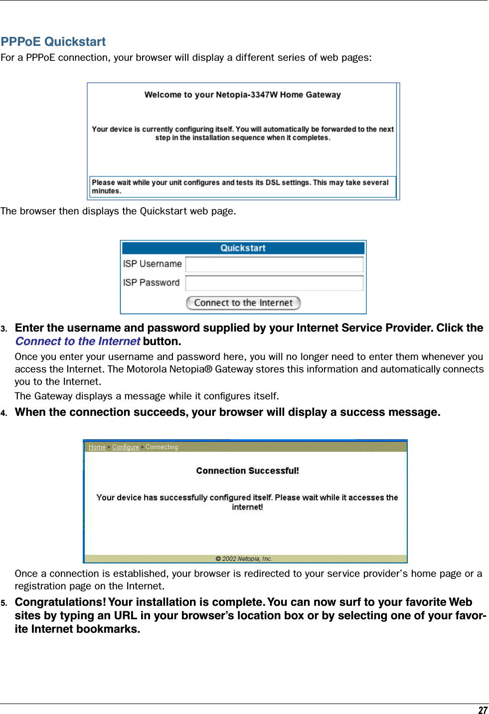
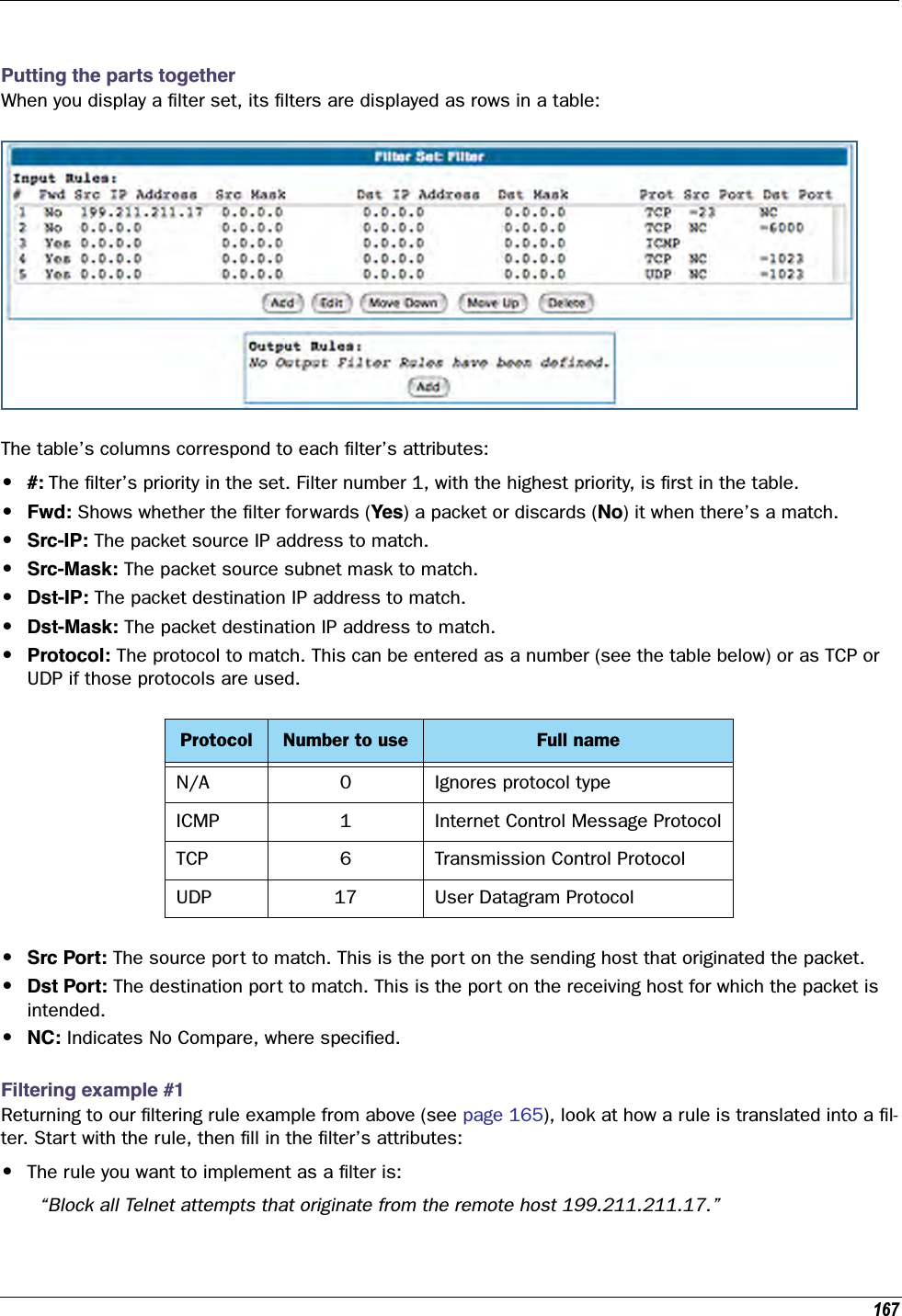
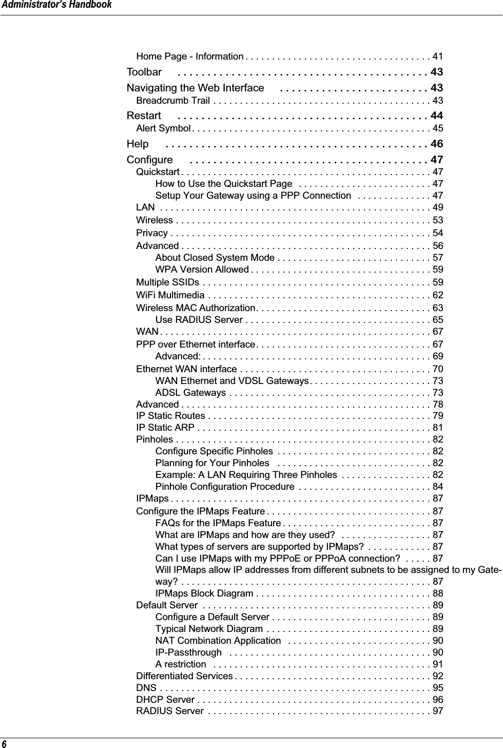
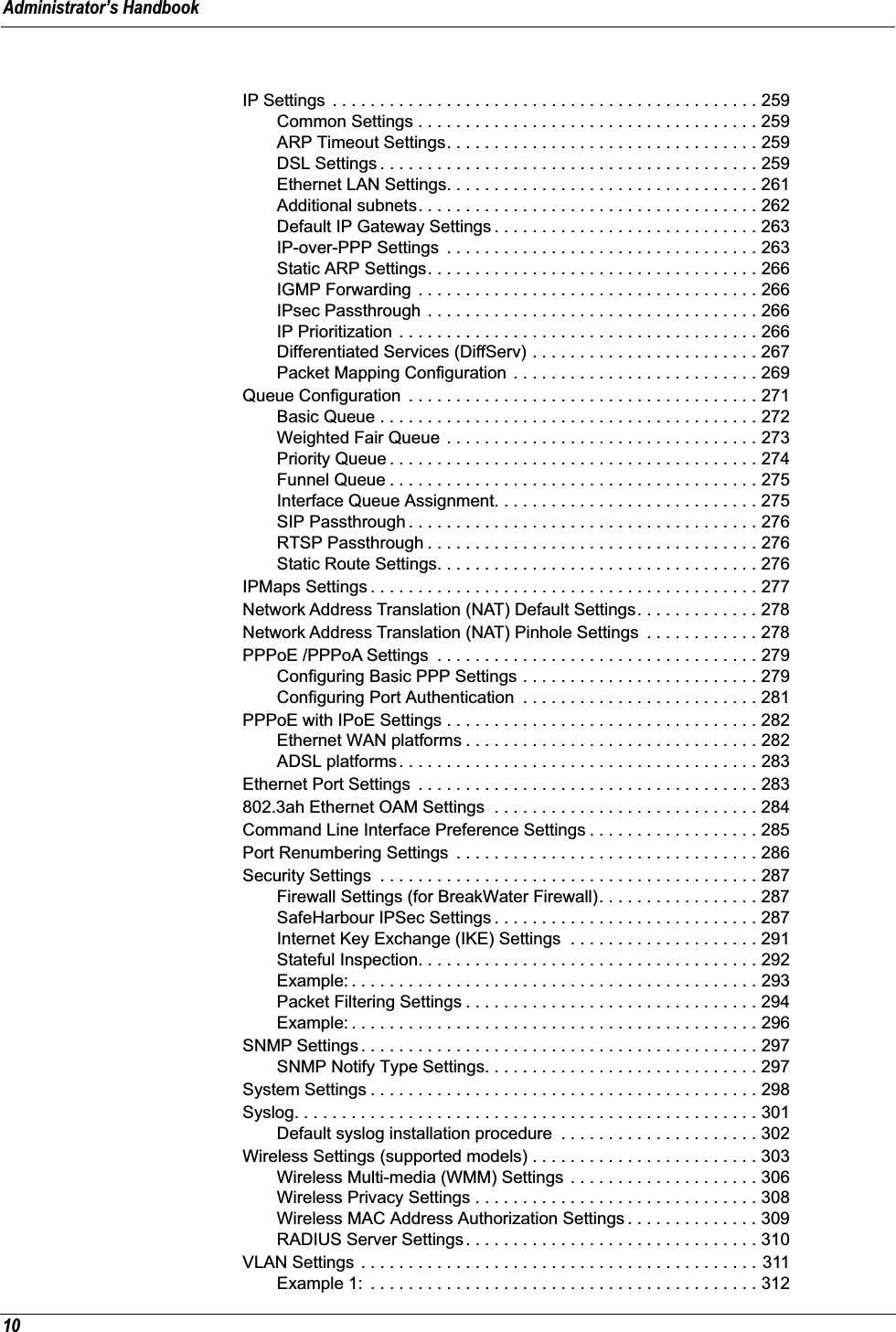
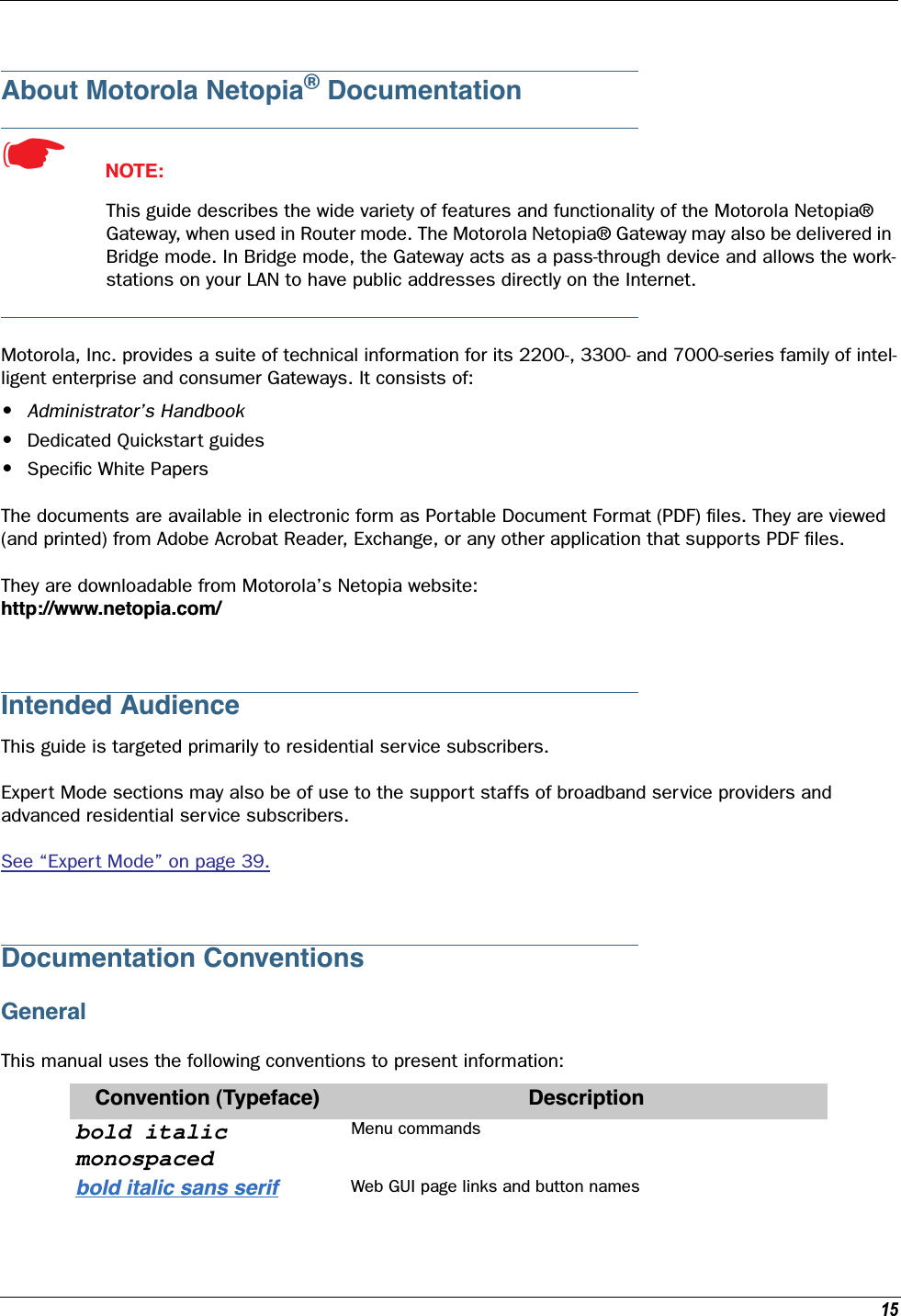
![Administrator’s Handbook22Setting up the Motorola Netopia® GatewayRefer to your Quickstart Guide for instructions on how to connect your Motorola Netopia® gateway to your power source, PC or local area network, and your Internet access point, whether it is a dedicated DSL outlet or a DSL or cable modem. Different Motorola Netopia® Gateway models are supplied for any of these con-nections. Be sure to enable Dynamic Addressing on your PC. Perform the following:Microsoft Windows: Step 1. Navigate to the TCP/IP Properties Control Panel. a. Some Windows versions follow a path like this:Start menu -> Settings -> Control Panel -> Network (or Network and Dial-up Connections -> Local Area Connection -> Properties) -> TCP/IP [your_network_card] or Internet Protocol [TCP/IP] -> Properties b. Some Windows versions follow a path like this:Start menu -> Con-trol Panel -> Net-work and Internet Connections -> Net-work Connections -> Local Area Connec-tion -> Properties -> Internet Protocol [TCP/IP] -> Proper-ties](https://usermanual.wiki/ARRIS/224742.User-Manual-Part-One/User-Guide-899049-Page-22.png)