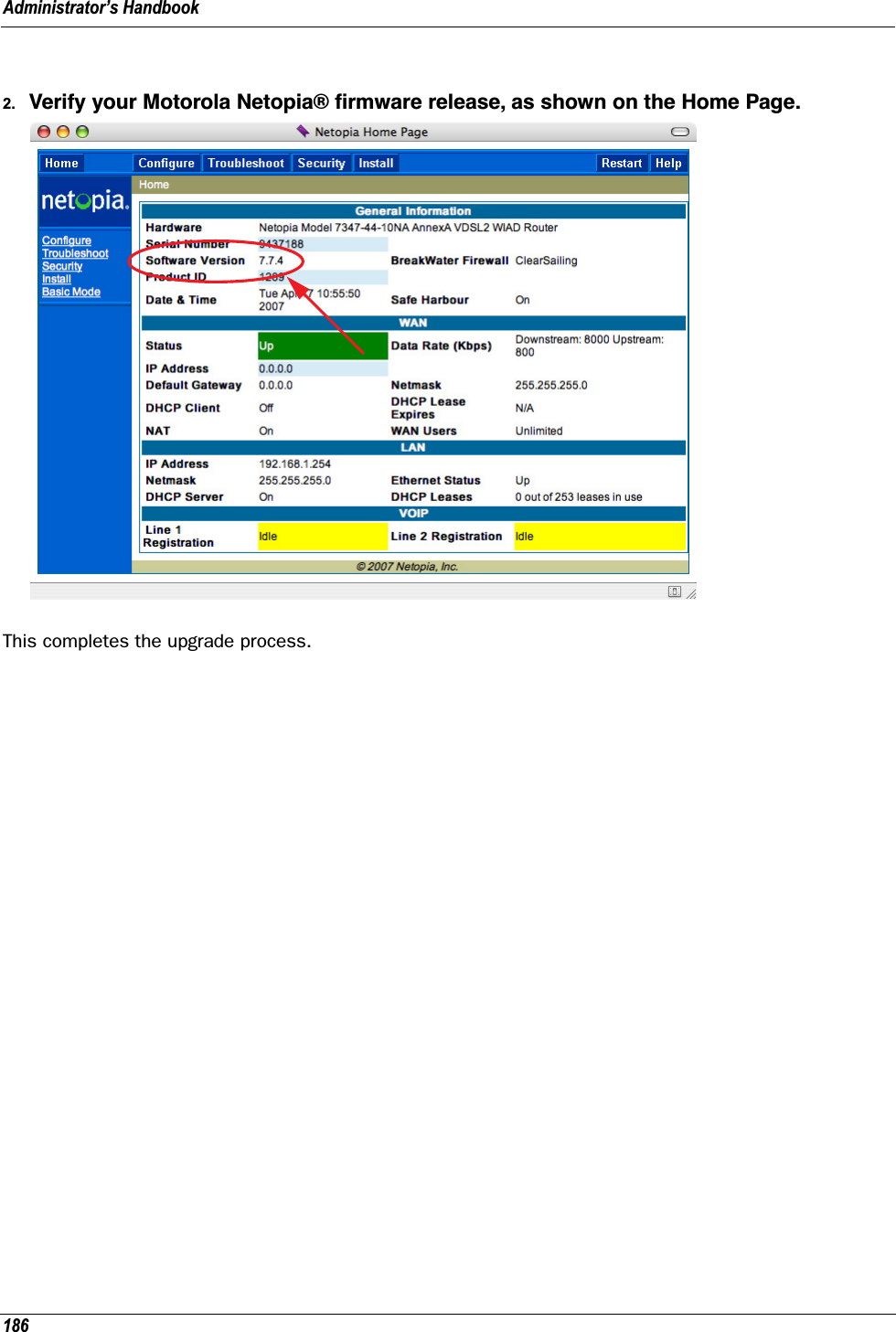
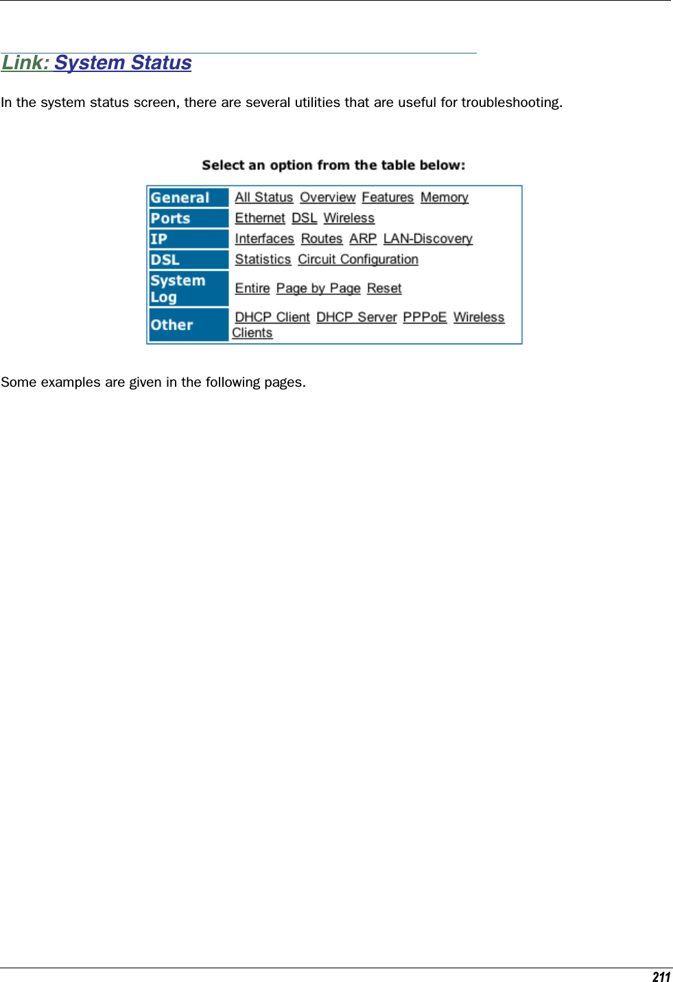
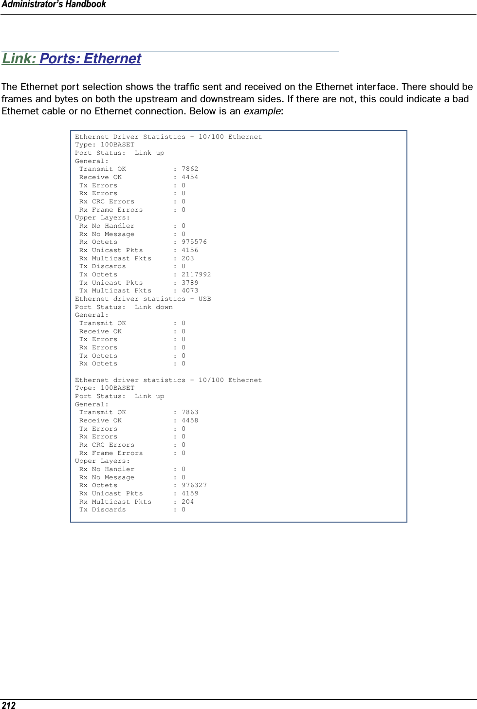
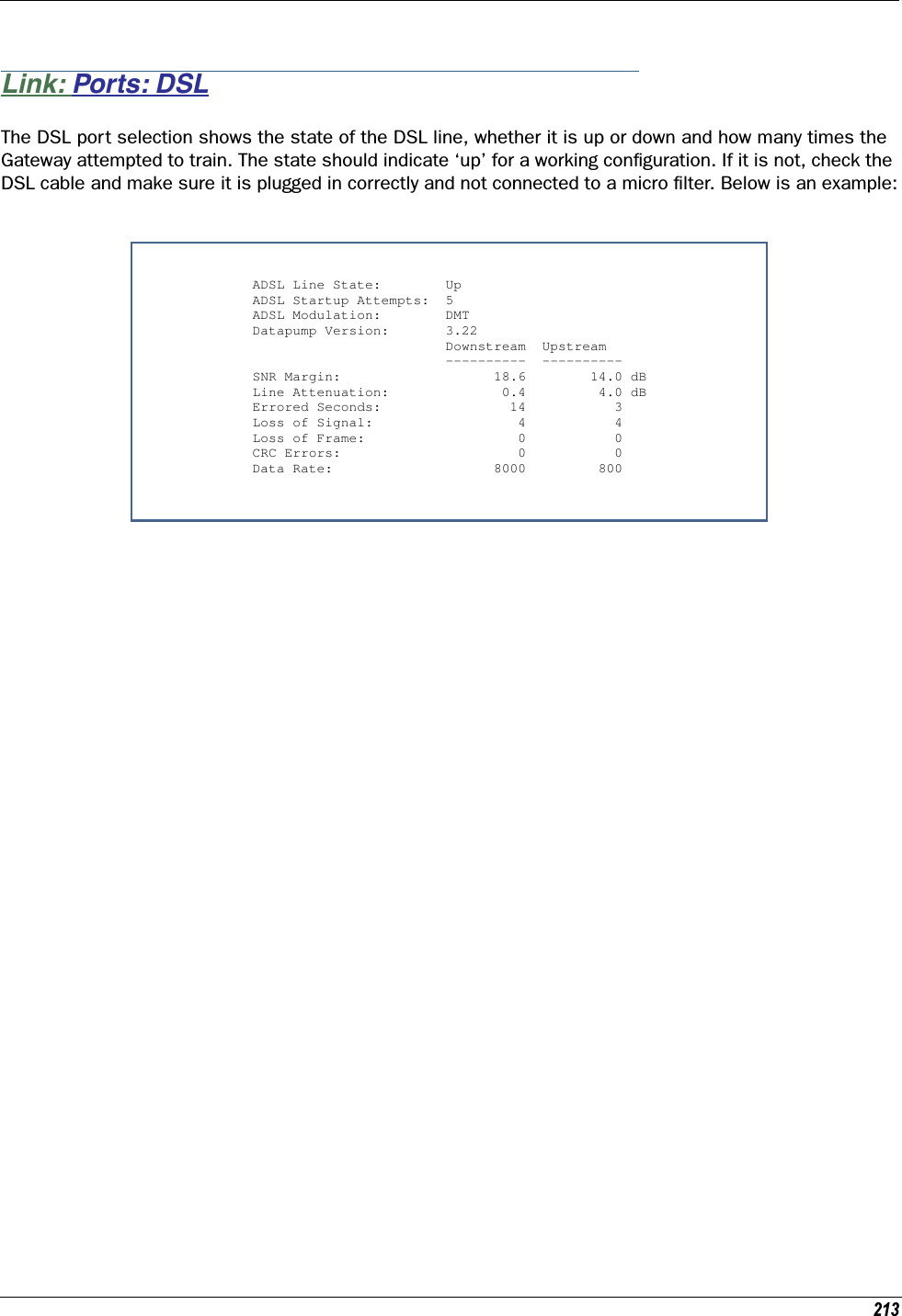
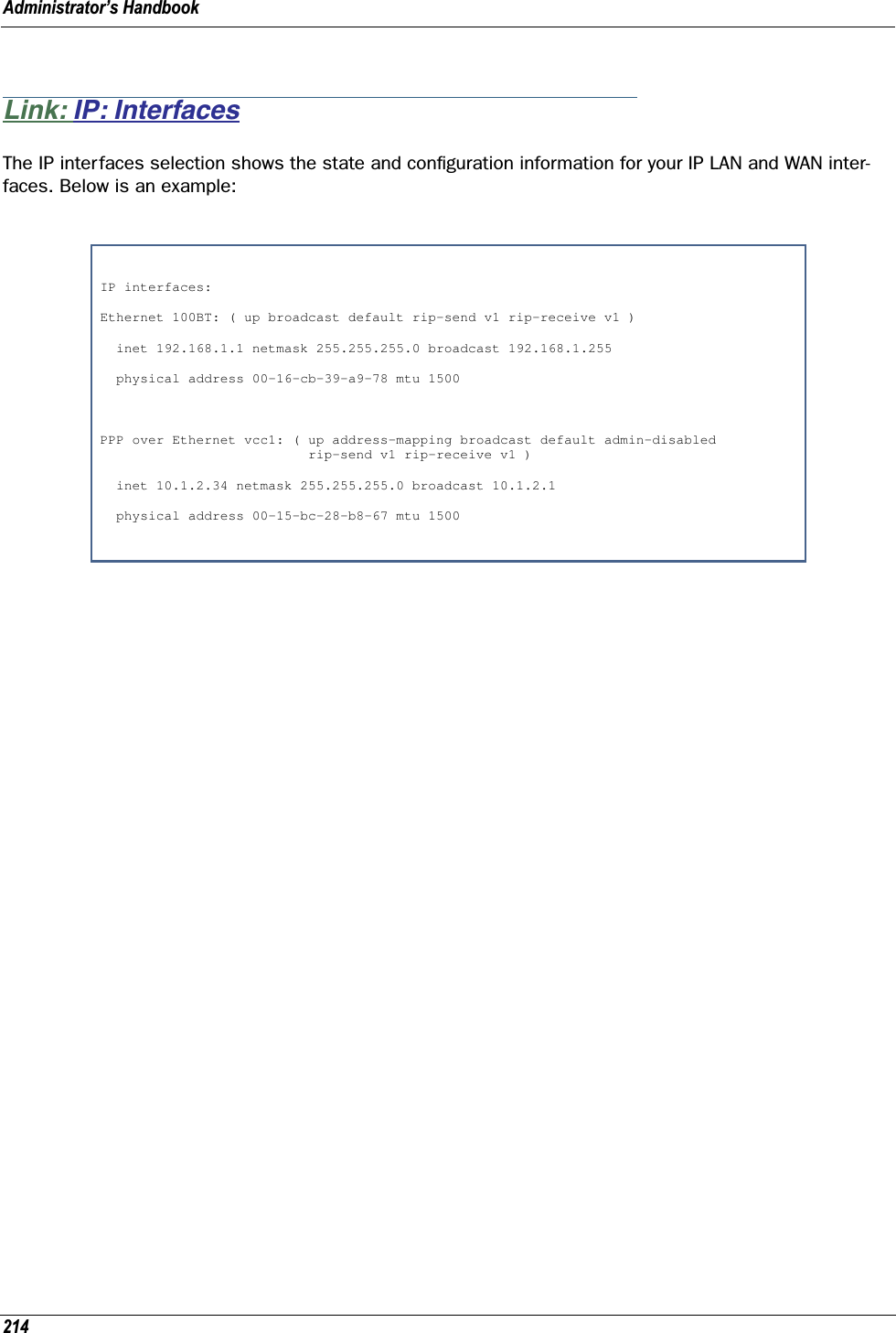
ARRIS 224762 ADSL2+802.11b/g Ethernet Modem User Manual Administrator s Handbook V7 7 4
ARRIS Group, Inc. ADSL2+802.11b/g Ethernet Modem Administrator s Handbook V7 7 4
UserManual.wiki
>
ARRIS
>
224762 User Manual
Users Manual
Navigation menu
Upload a User Manual
Namespaces
Wiki Guide
HTML
PDF
Info
Views
User Manual
Discussion / Help
Navigation
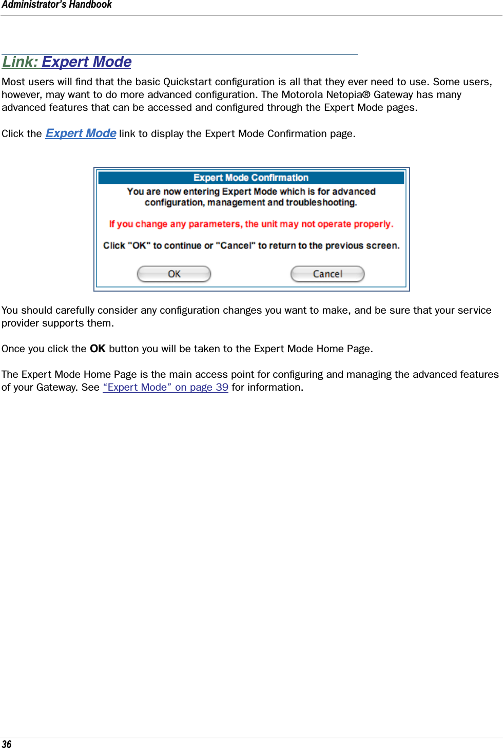
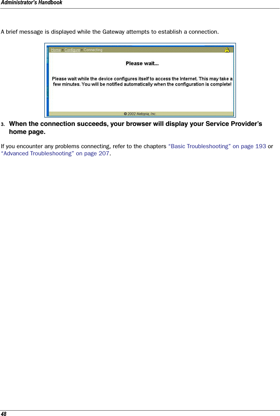
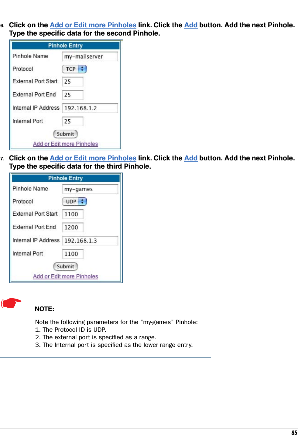
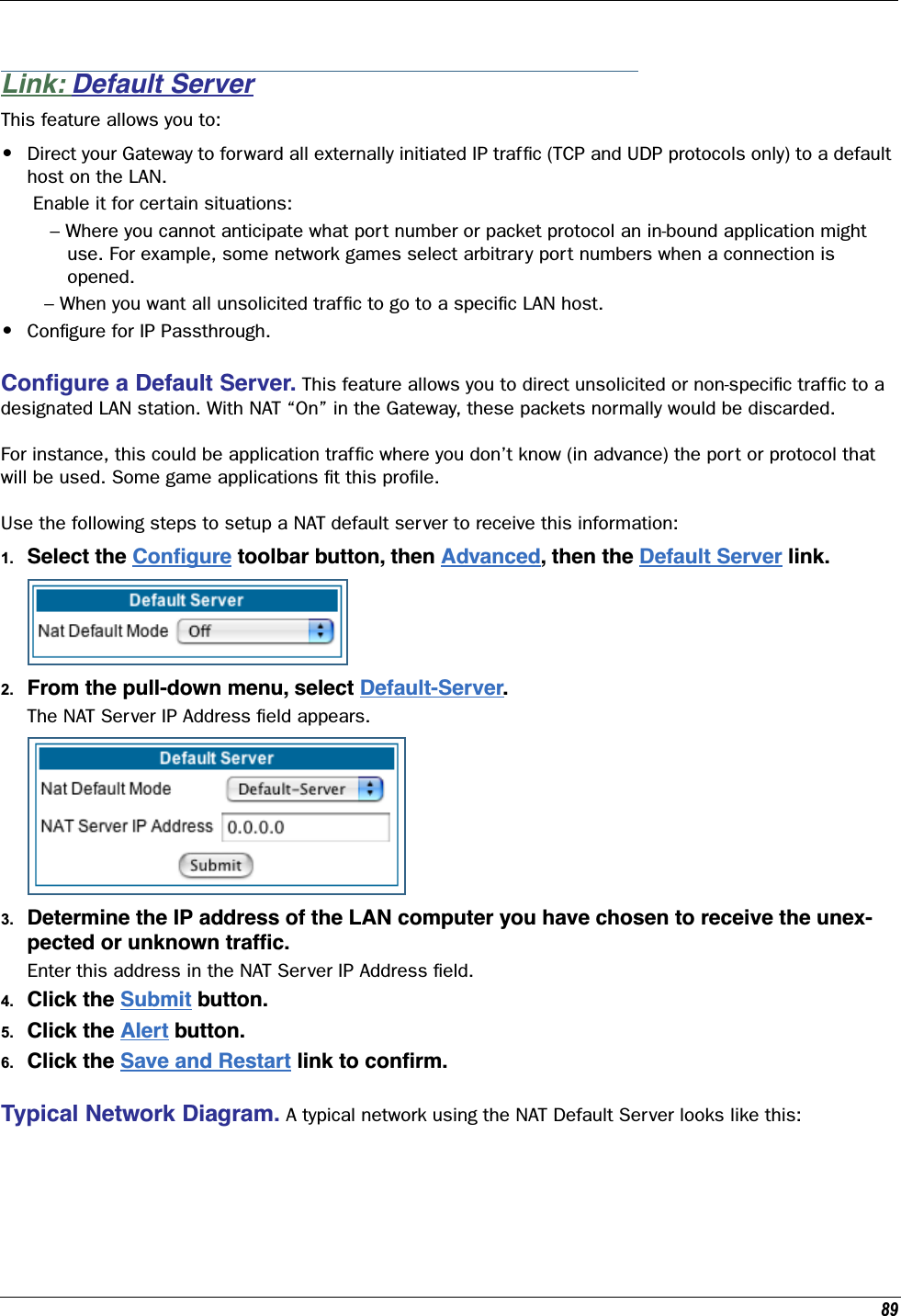
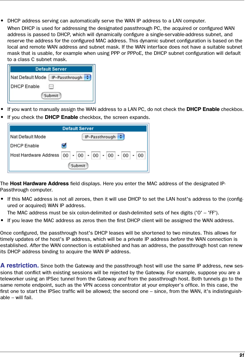
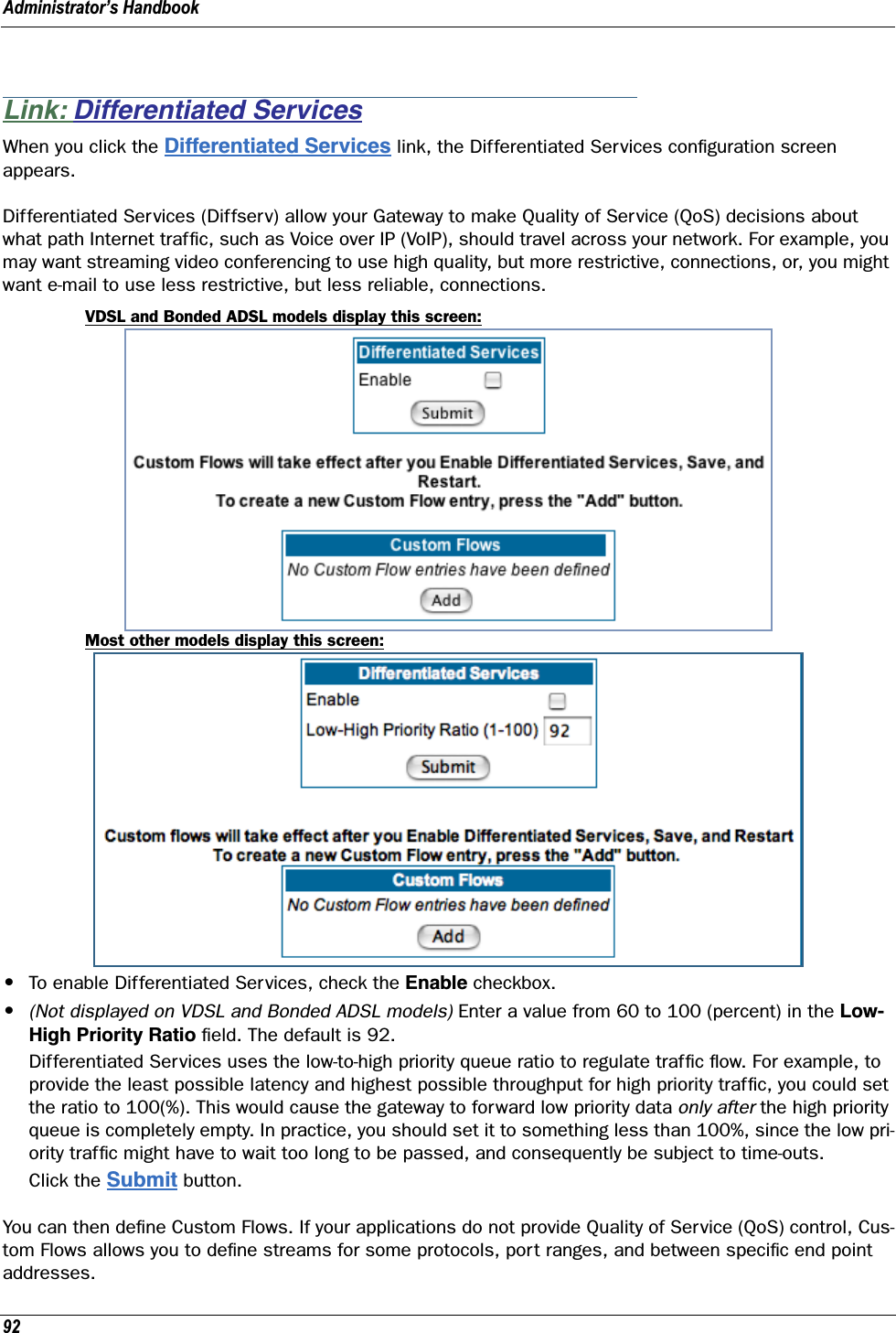
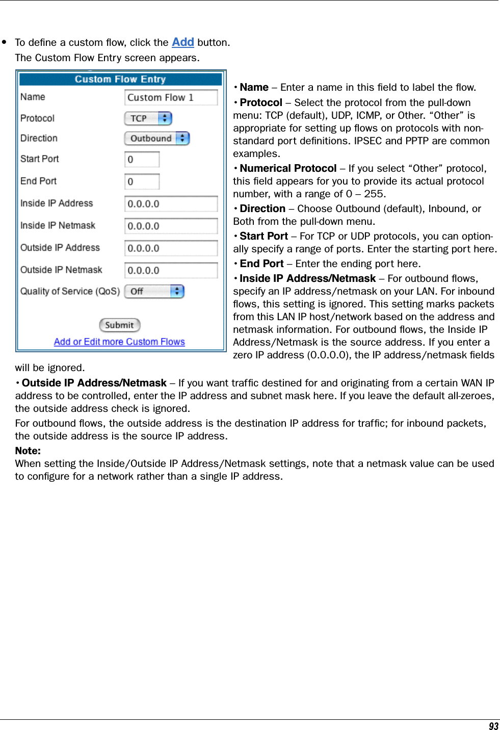
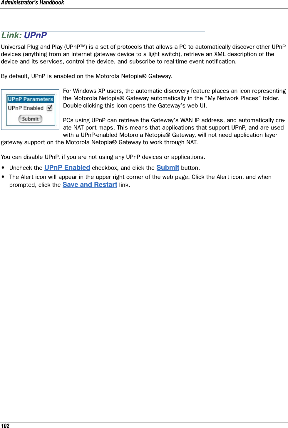
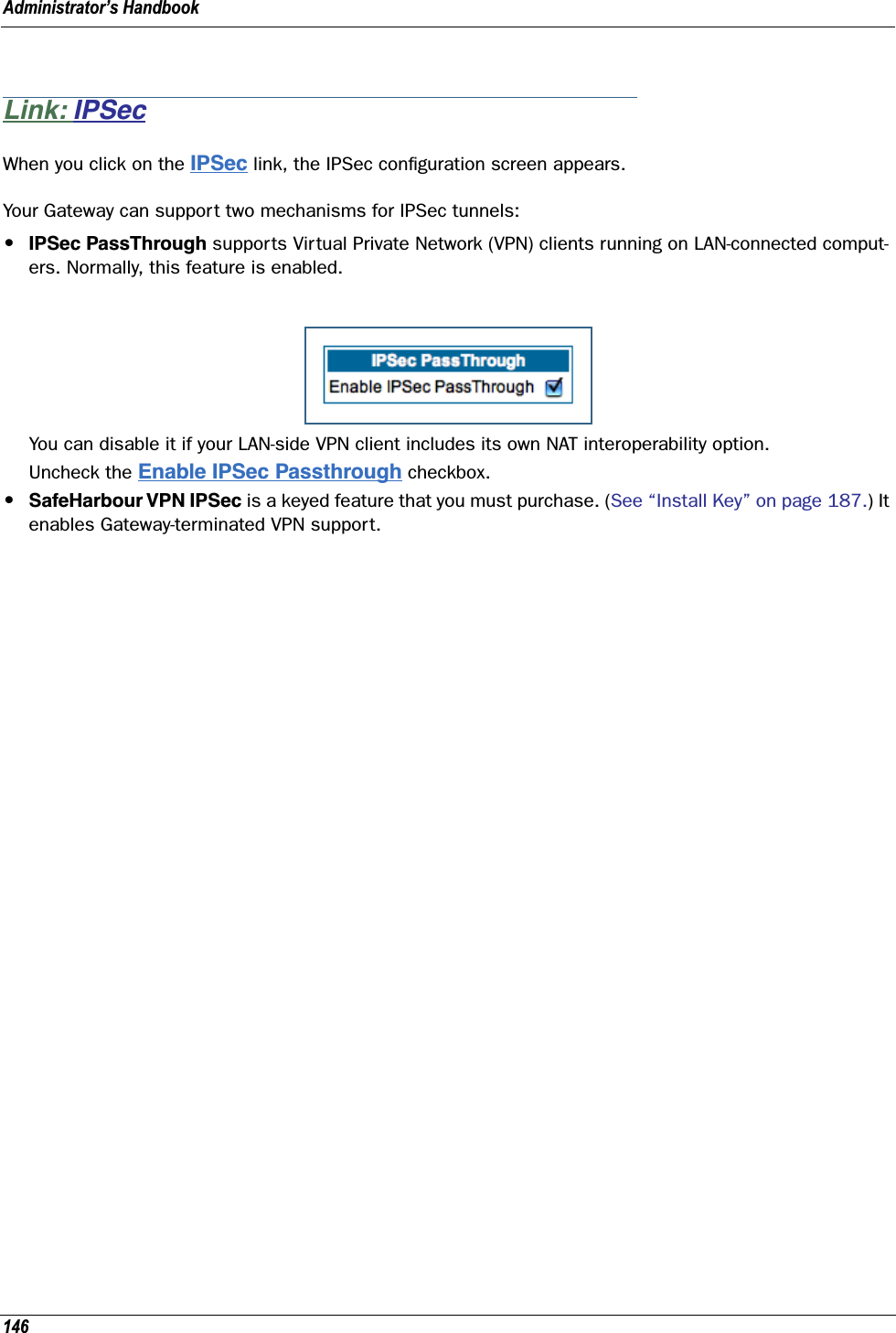
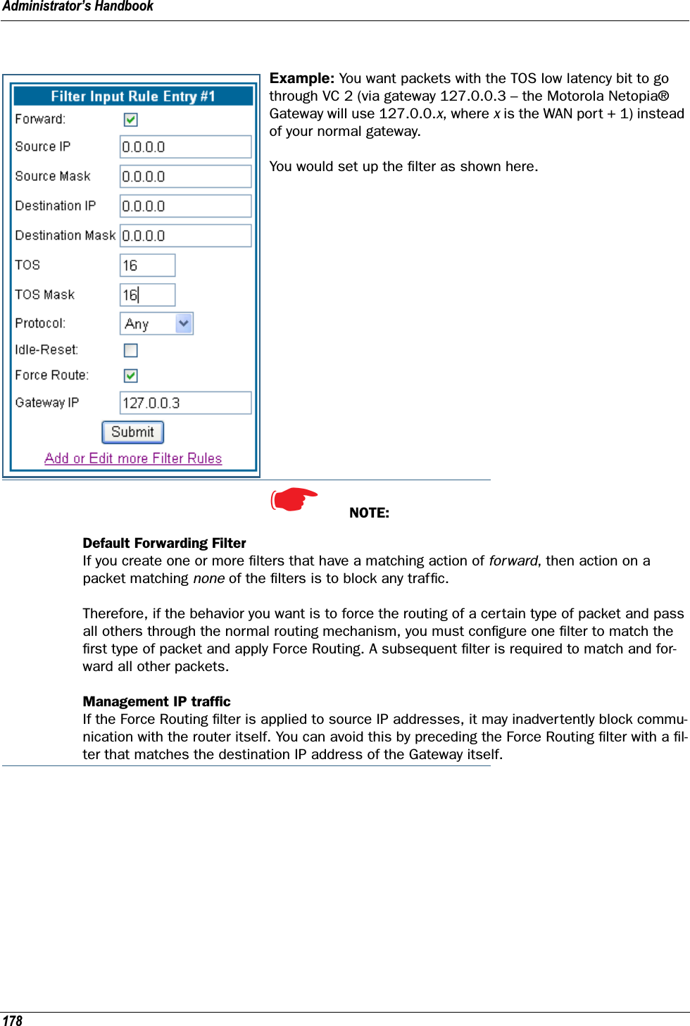
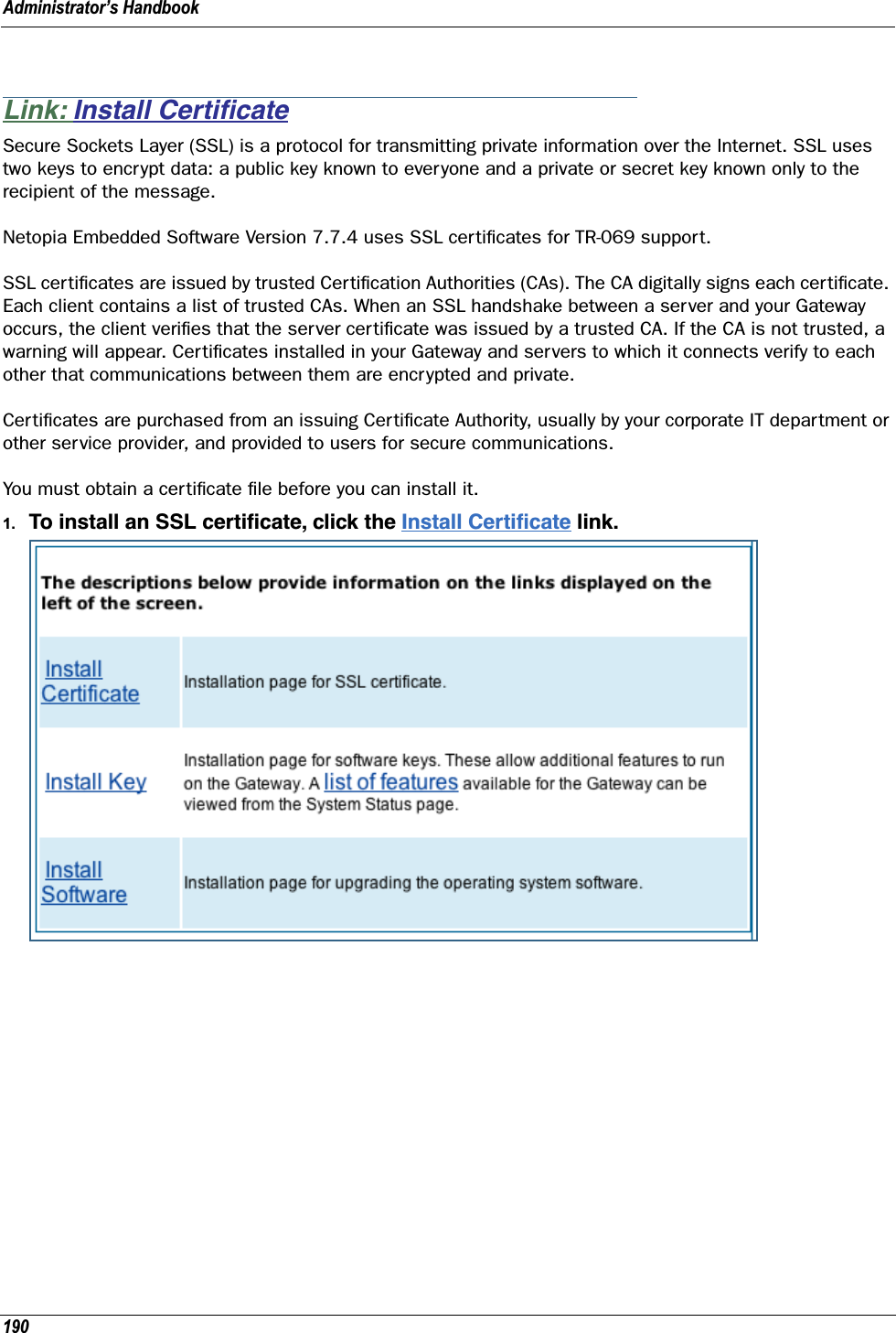
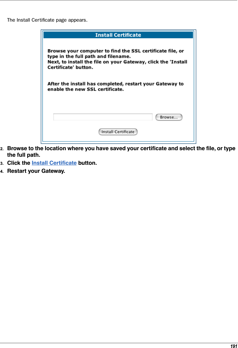
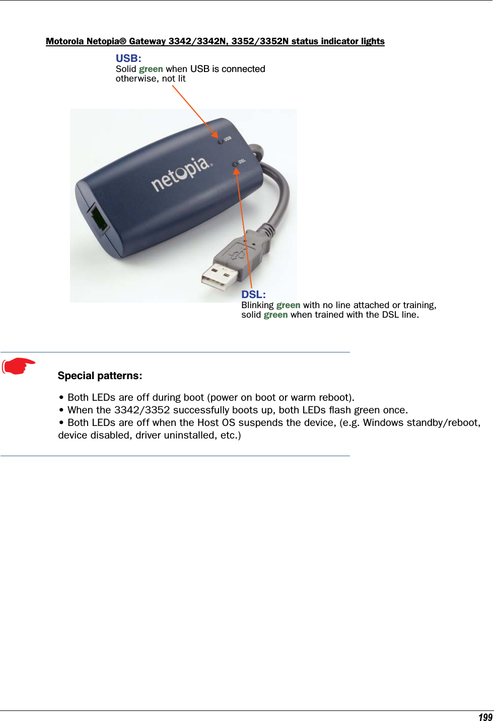
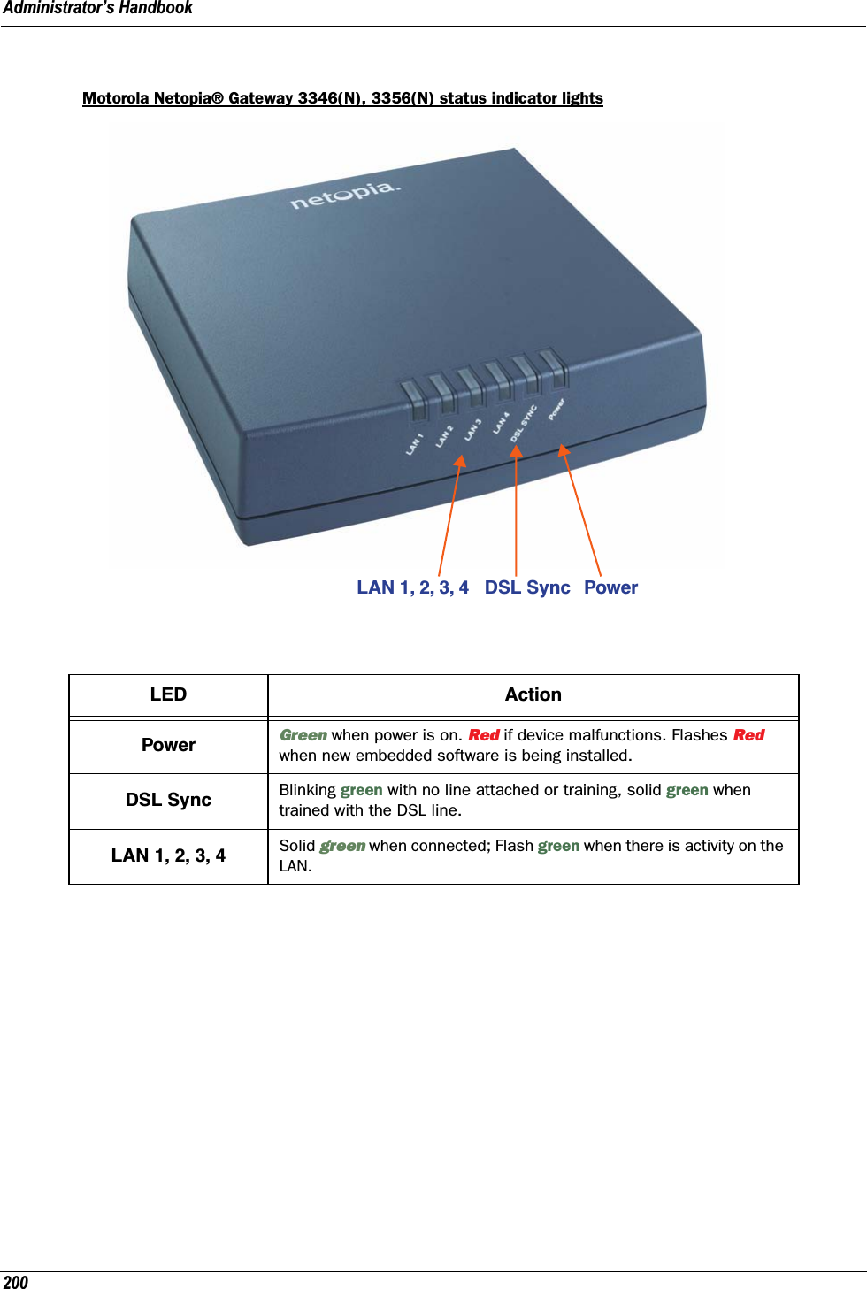
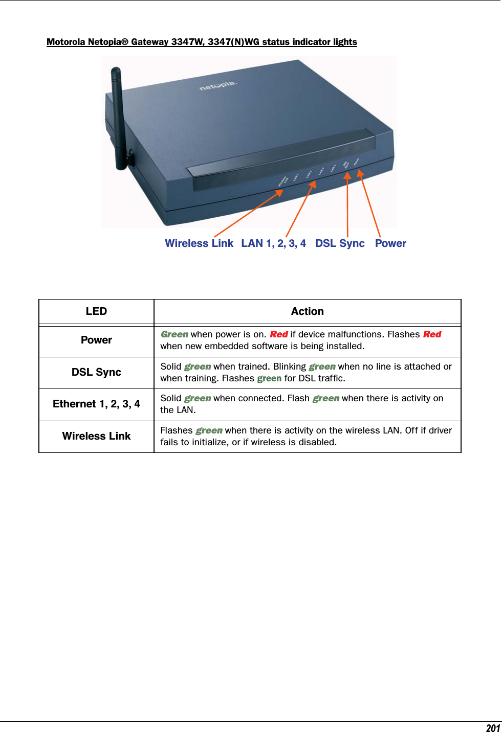
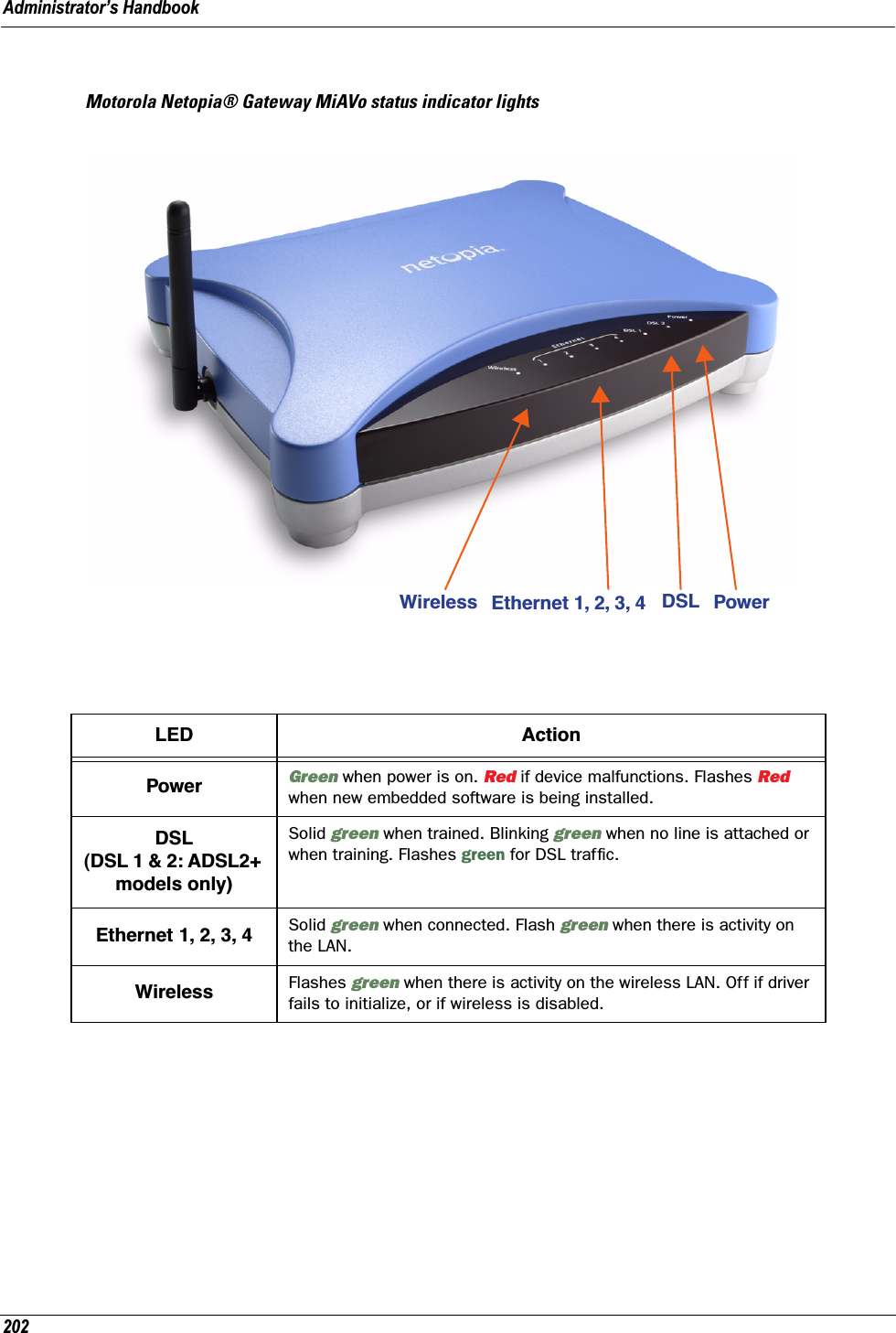
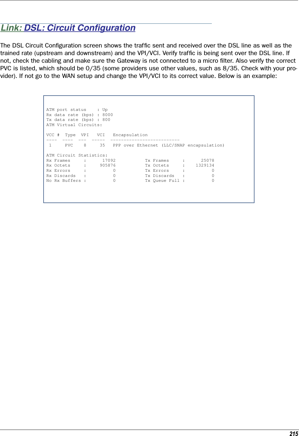
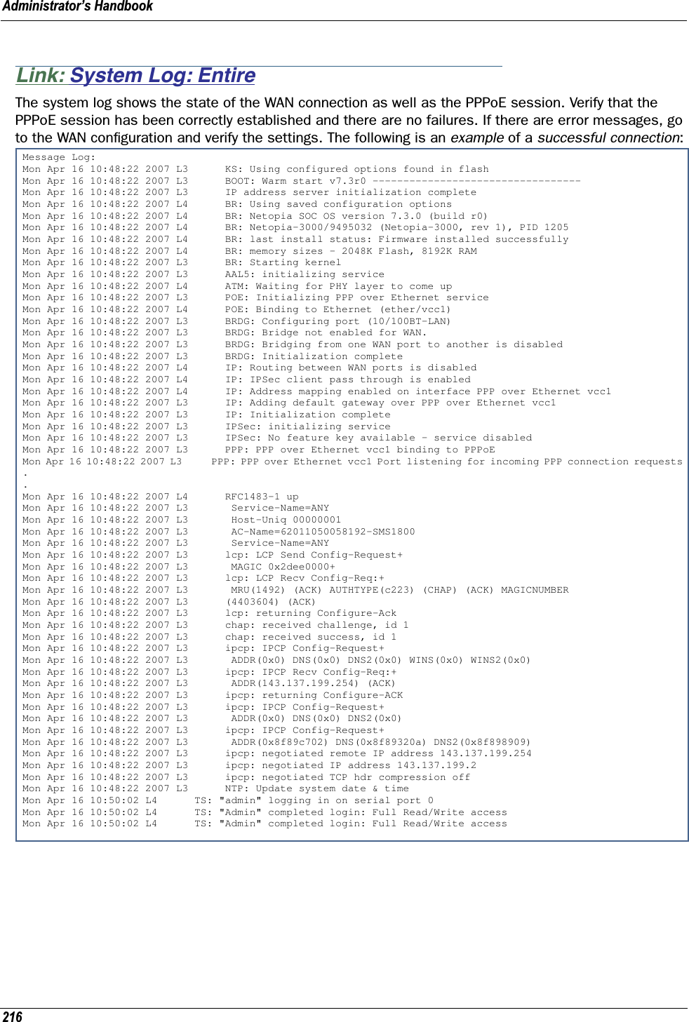
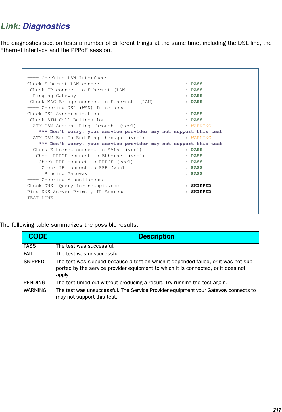
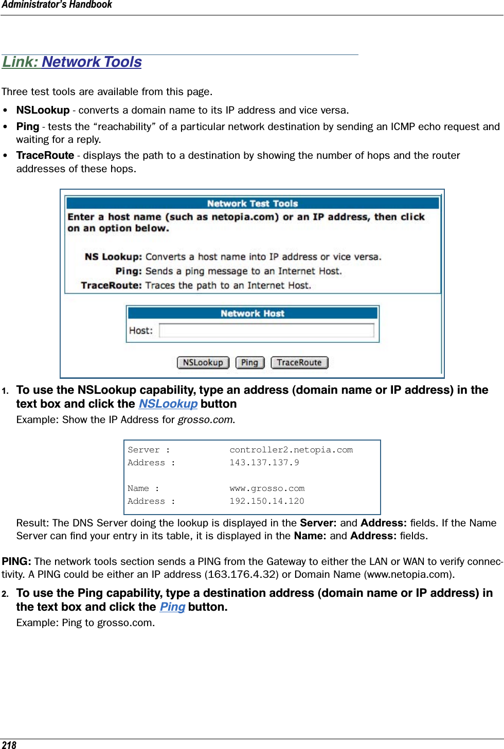
![Copyright remains Eric Young's, and as such any Copyright notices in the code are not to be removed. If this package is used in a product, Eric Young should be given attribution as the author of the parts of the library used. This can be in the form of a textual message at program startup or in documentation (online or textual) provided with the package.Redistribution and use in source and binary forms, with or without modification, are permitted provided that the following conditions are met: 1. Redistributions of source code must retain the copyright notice, this list of conditions and the following disclaimer. 2. Redistributions in binary form must reproduce the above copyright notice, this list of conditions and the following disclaimer in the documentation and/or other materials provided with the distribution. 3. All advertising materials mentioning features or use of this software must display the following acknowledgement: “This product includes cryptographic software written by Eric Young (eay@cryptsoft.com)” The word 'cryptographic' can be left out if the routines from the library being used are not cryptographic related :-). 4. If you include any Windows specific code (or a derivative thereof) from the apps directory (application code) you must include an acknowledgement: “This product includes software written by Tim Hudson (tjh@cryptsoft.com)”THIS SOFTWARE IS PROVIDED BY ERIC YOUNG ``AS IS'' AND ANY EXPRESS OR IMPLIED WARRANTIES, INCLUDING, BUT NOT LIMITED TO, THE IMPLIED WARRANTIES OF MERCHANTABILITY AND FITNESS FOR A PARTICULAR PURPOSE ARE DISCLAIMED. IN NO EVENT SHALL THE AUTHOR OR CONTRIBUTORS BE LIABLE FOR ANY DIRECT, INDIRECT, INCIDENTAL, SPECIAL, EXEMPLARY, OR CONSEQUENTIAL DAMAGES (INCLUDING, BUT NOT LIMITED TO, PROCUREMENT OF SUBSTITUTE GOODS OR SERVICES; LOSS OF USE, DATA, OR PROFITS; OR BUSINESS INTERRUPTION) HOWEVER CAUSED AND ON ANY THEORY OF LIABILITY, WHETHER IN CONTRACT, STRICT LIABILITY, OR TORT (INCLUDING NEGLIGENCE OR OTHERWISE) ARISING IN ANY WAY OUT OF THE USE OF THIS SOFTWARE, EVEN IF ADVISED OF THE POSSIBILITY OF SUCH DAMAGE.The licence and distribution terms for any publicly available version or derivative of this code cannot be changed. i.e. this code cannot simply be copied and put under another distribution licence [including the GNU Public Licence.] Portions of this software are based in part on the work of the following: Copyright (C) 1995, 1996, 1997, and 1998 WIDE Project. All rights reserved.Redistribution and use in source and binary forms, with or without modification, are permitted provided that the following conditions are met: 1. Redistributions of source code must retain the above copyright notice, this list of conditions and the following disclaimer. 2. Redistributions in binary form must reproduce the above copyright notice, this list of conditions and the following disclaimer in the documentation and/or other materials provided with the distribution. 3. Neither the name of the project nor the names of its contributors may be used to endorse or promote products derived from this software without specific prior written permission.THIS SOFTWARE IS PROVIDED BY THE PROJECT AND CONTRIBUTORS ``AS IS'' AND ANY EXPRESS OR IMPLIED WARRANTIES, INCLUDING, BUT NOT LIMITED TO, THE IMPLIED WARRANTIES OF MERCHANTABILITY AND FITNESS FOR A PARTICULAR PURPOSE ARE DISCLAIMED. IN NO EVENT SHALL THE PROJECT OR CONTRIBUTORS BE LIABLE FOR ANY DIRECT, INDIRECT, INCIDENTAL, SPECIAL, EXEMPLARY, OR CONSEQUENTIAL DAMAGES (INCLUDING, BUT NOT LIMITED TO, PROCUREMENT OF SUBSTITUTE GOODS OR SERVICES; LOSS OF USE, DATA, OR PROFITS; OR BUSINESS INTERRUPTION) HOWEVER CAUSED AND ON ANY THEORY OF LIABILITY, WHETHER IN CONTRACT, STRICT LIABILITY, OR TORT (INCLUDING NEGLIGENCE OR OTHERWISE) ARISING IN ANY WAY OUT OF THE USE OF THIS SOFTWARE, EVEN IF ADVISED OF THE POSSIBILITY OF SUCH DAMAGE. Portions of this software are based in part on the work of the following: Copyright (C) 1990, RSA Data Security, Inc. All rights reserved.<<RSA Data Security, Inc. MD5 Message-Digest Algorithm>>License to copy and use this software is granted provided that it is identified as the “RSA Data Security, Inc. MD5 Message Digest Algorithm” in all material mentioning or referencing this software or this function.License is also granted to make and use derivative works provided that such works are identified as “derived from the RSA Data Security, Inc. MD5 Message-Digest Algorithm” in all material mentioning or referencing the derived work.<<RSA Data Security, Inc. MD4 Message-Digest Algorithm>>License to copy and use this software is granted provided that it is identified as the “RSA Data Security, Inc. MD4 Message Digest Algorithm” in all material mentioning or referencing this software or this function.License is also granted to make and use derivative works provided that such works are identified as “derived from the RSA Data Security, Inc. MD4 Message-Digest Algorithm” in all material mentioning or referencing the derived work.](https://usermanual.wiki/ARRIS/224762/User-Guide-1097848-Page-3.png)
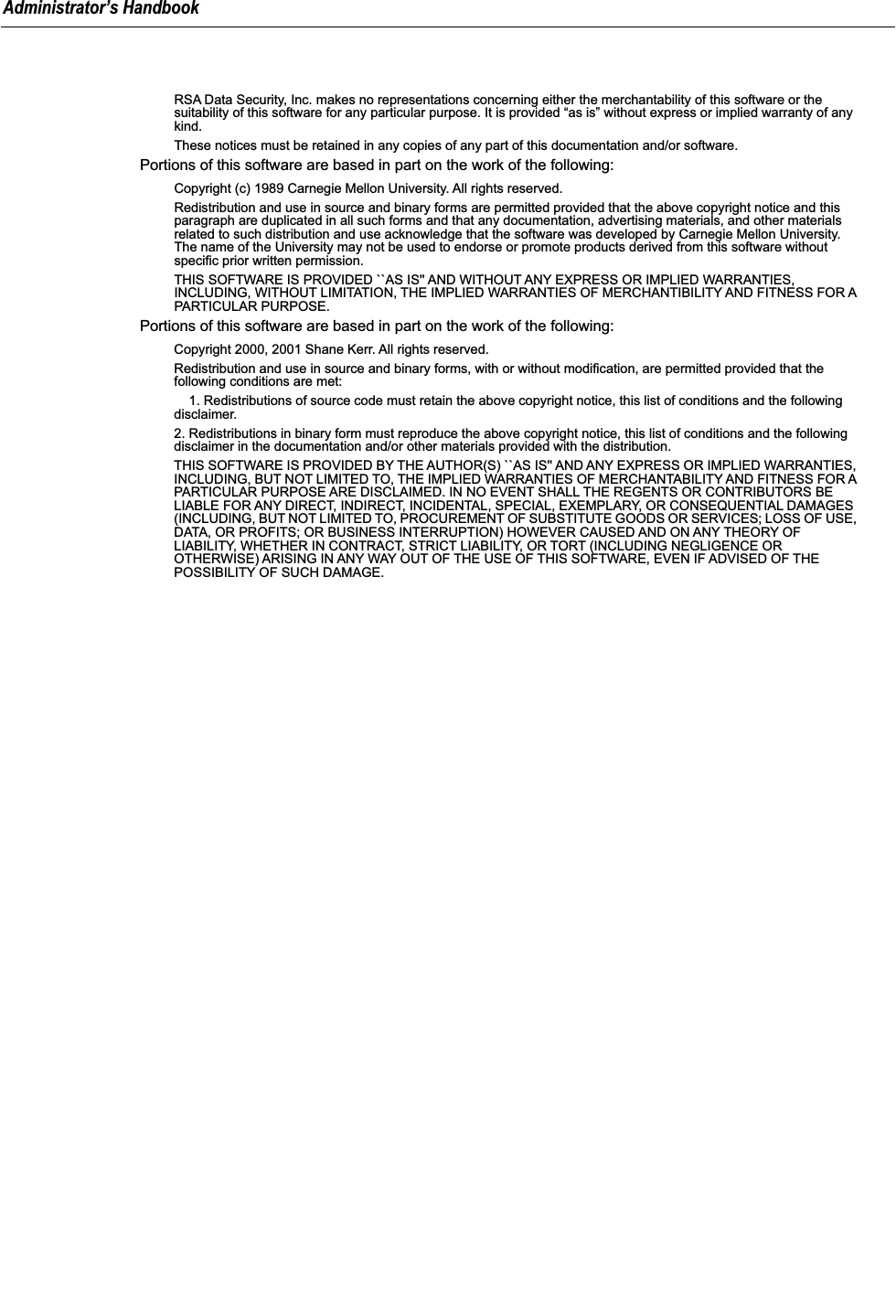
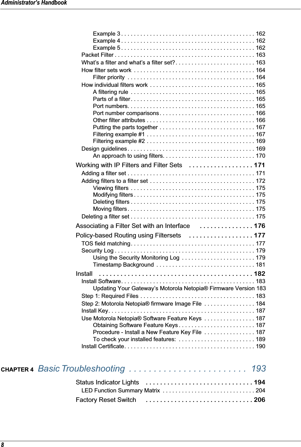
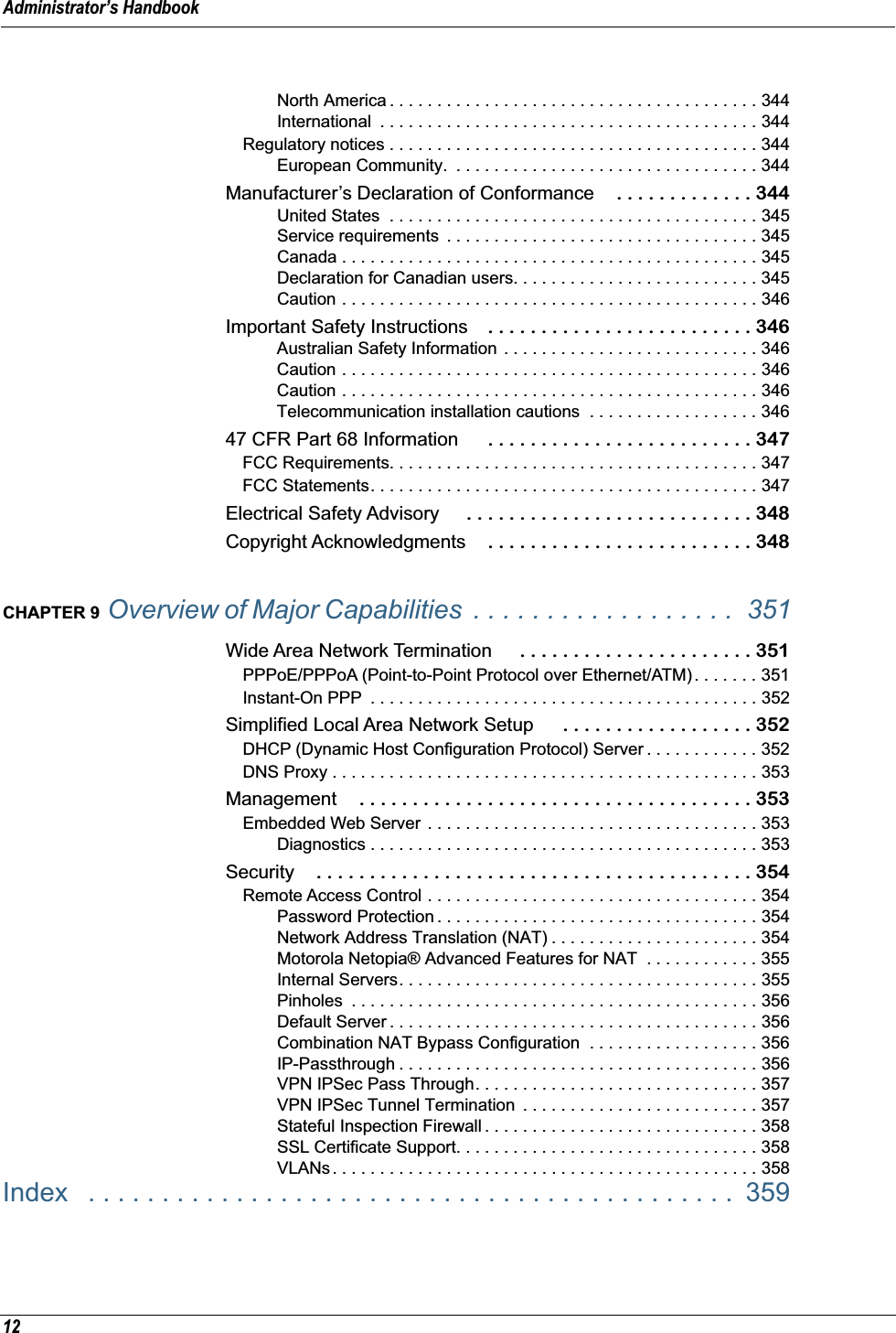
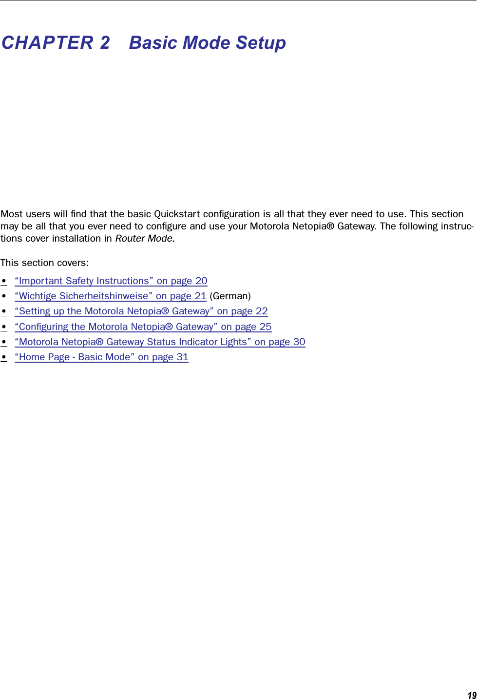
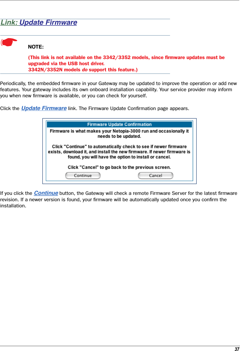
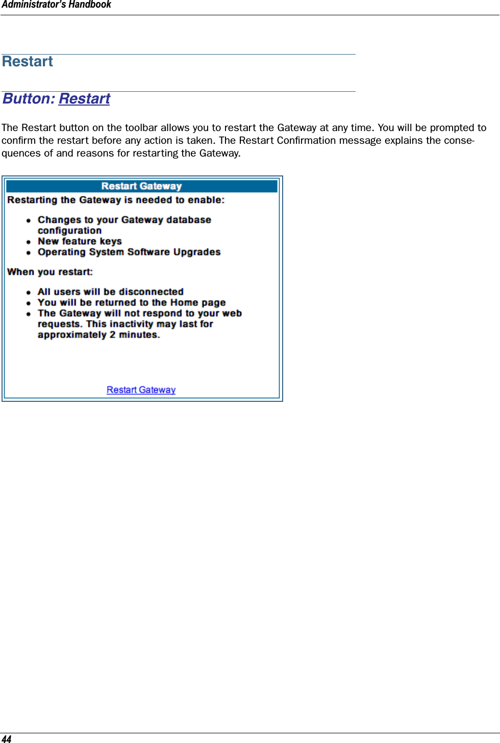
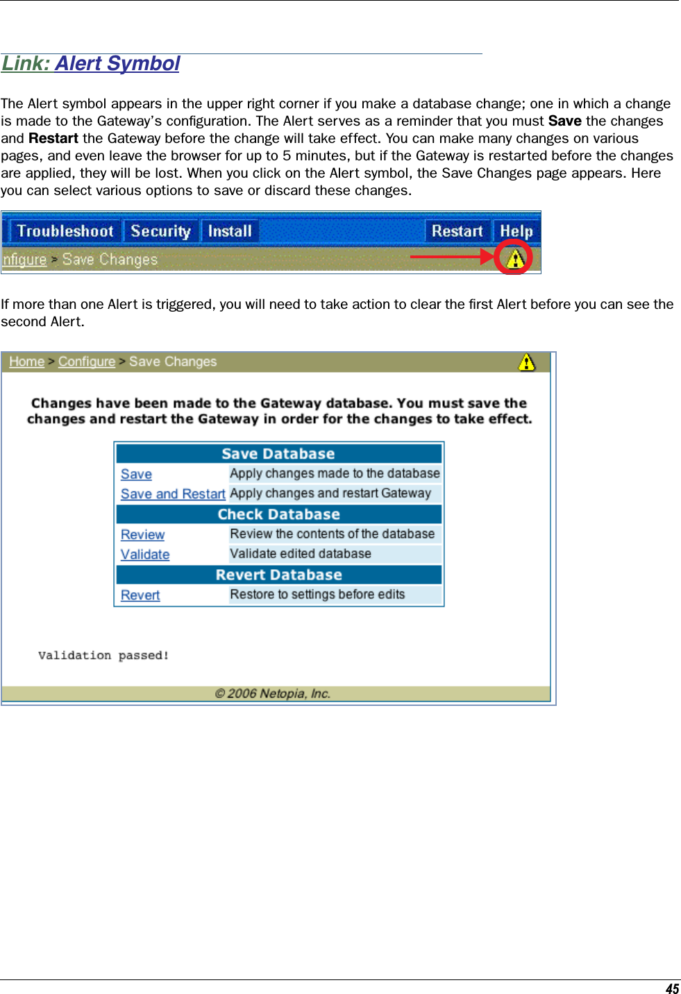
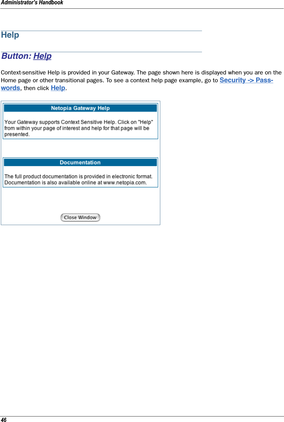
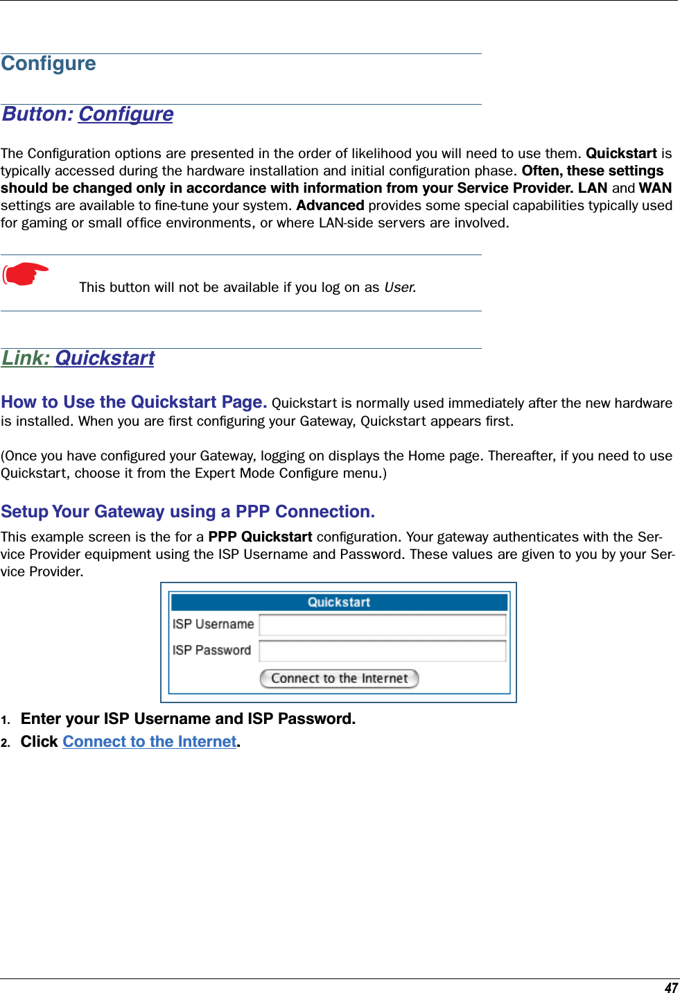
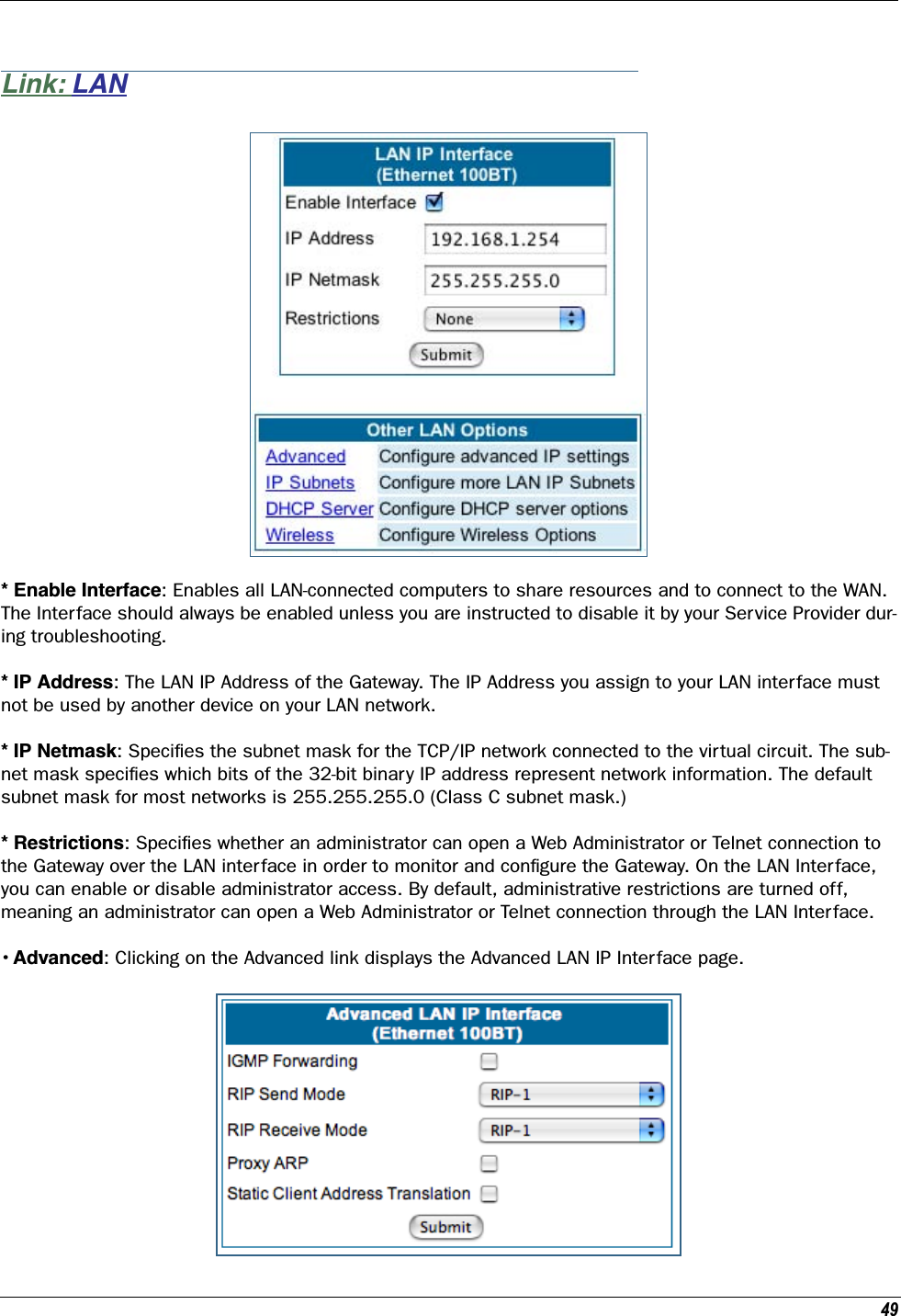
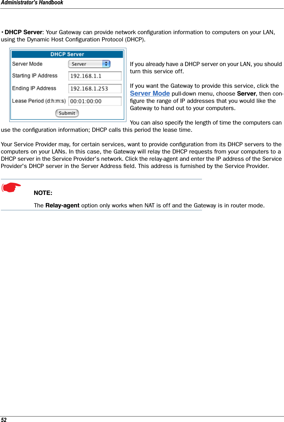
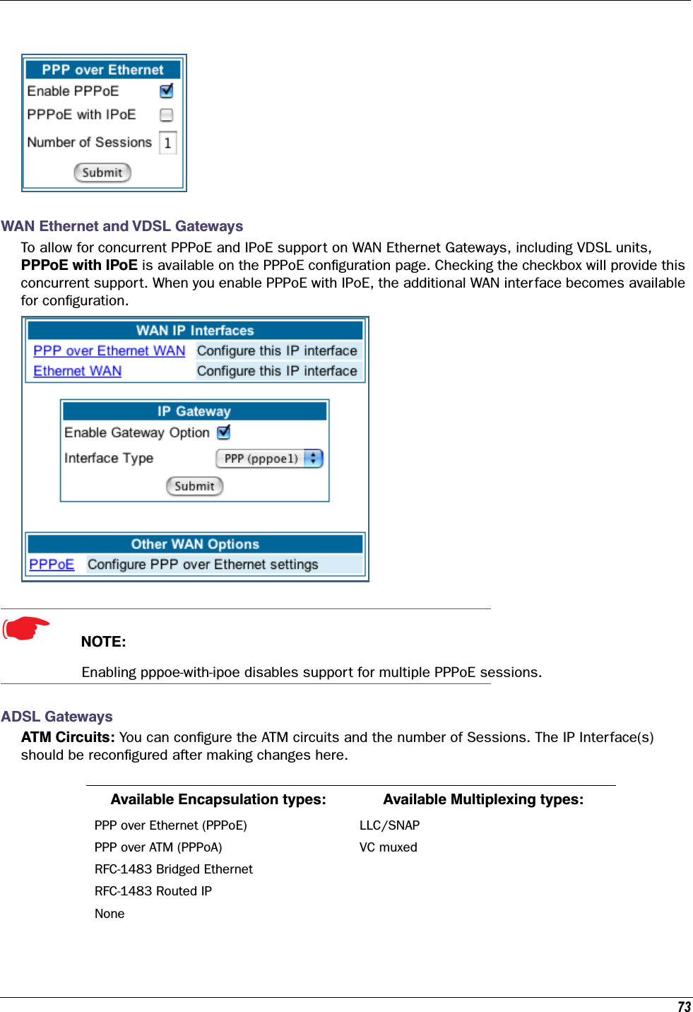
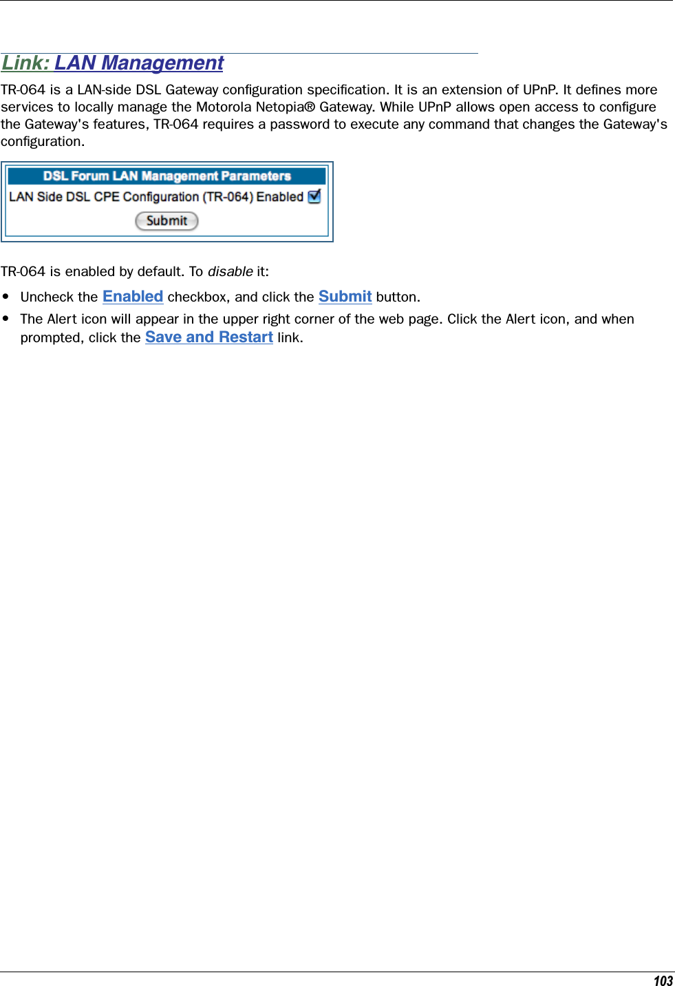
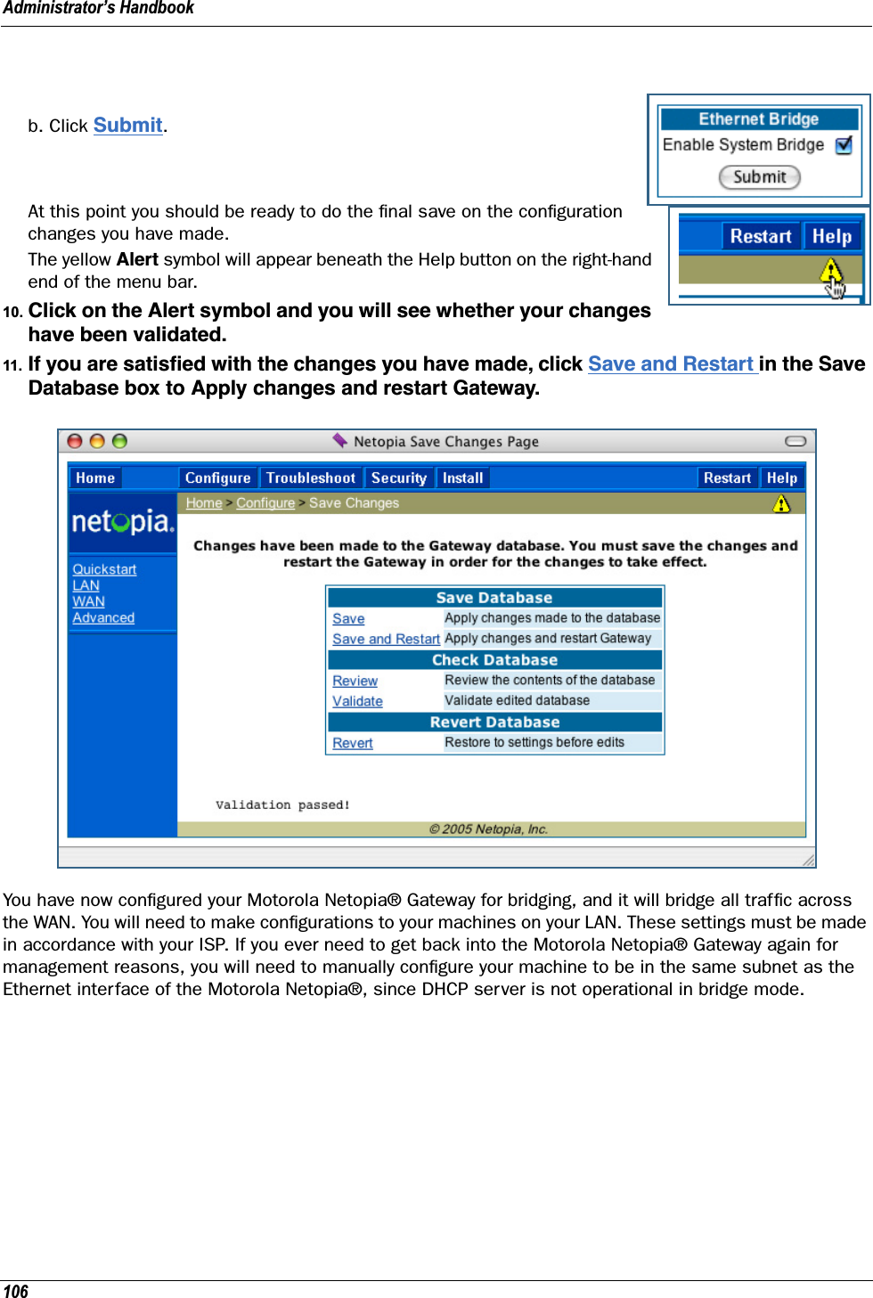
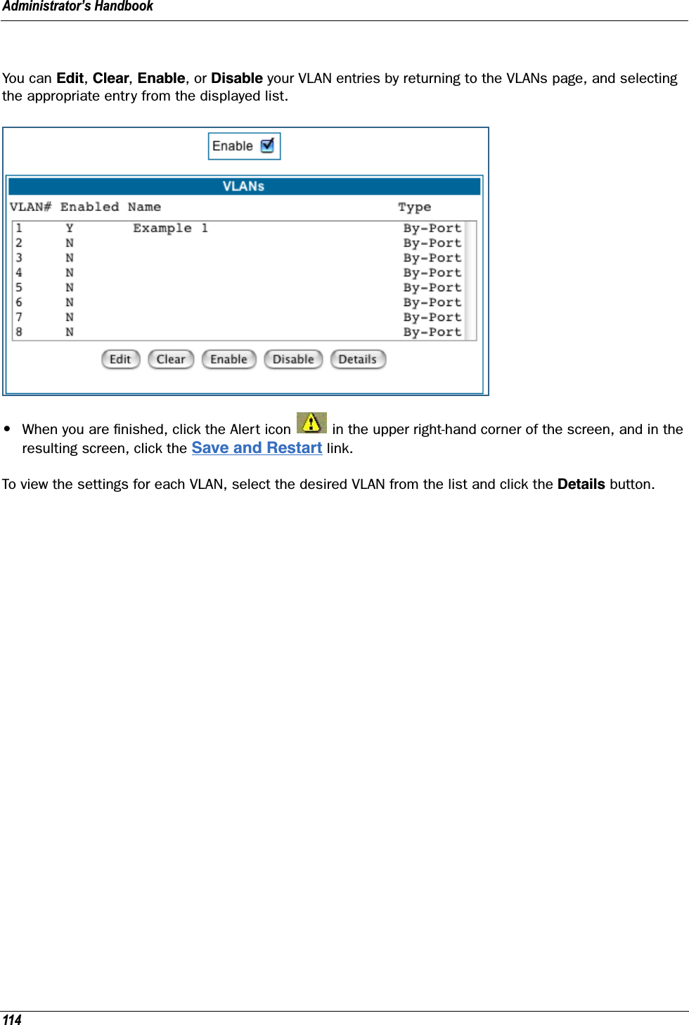
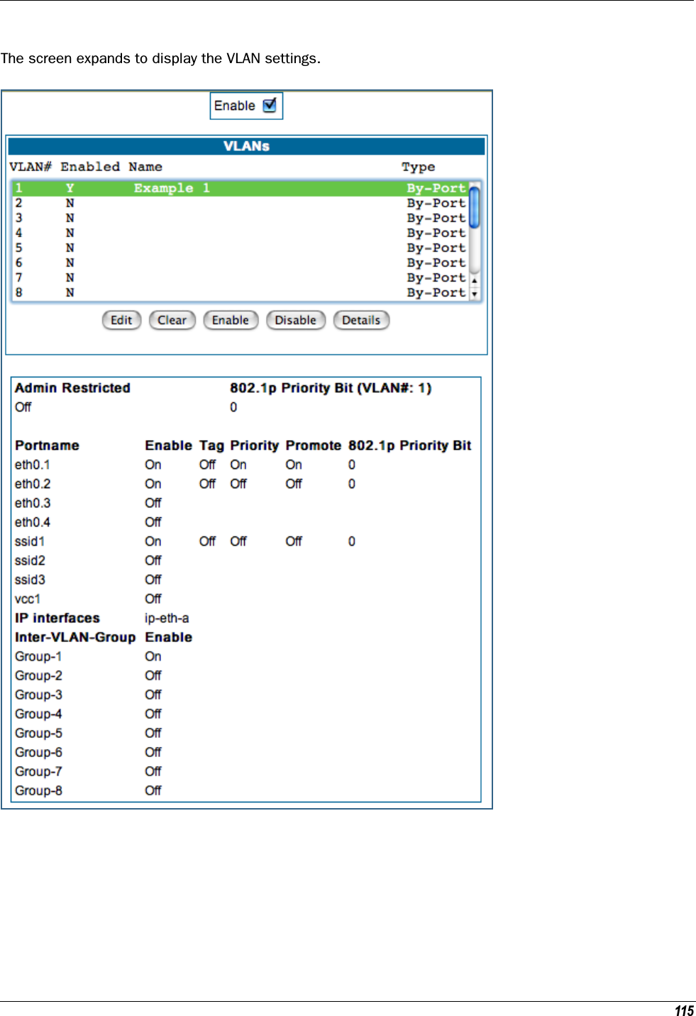
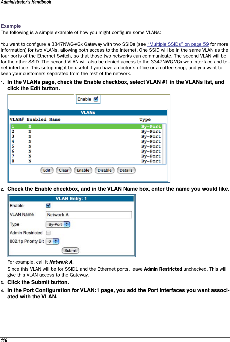
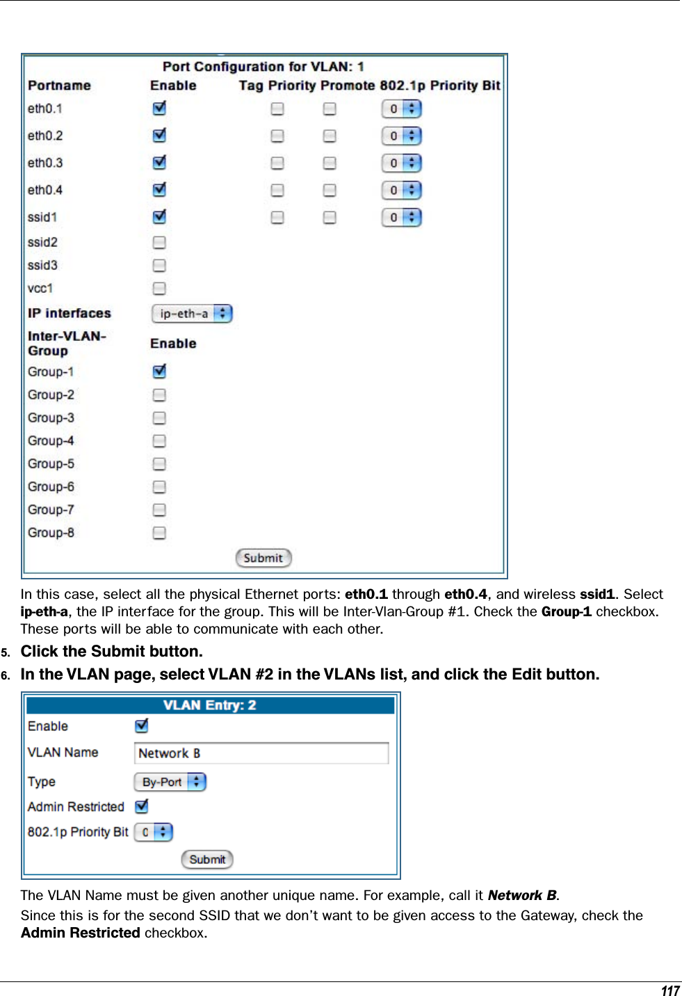
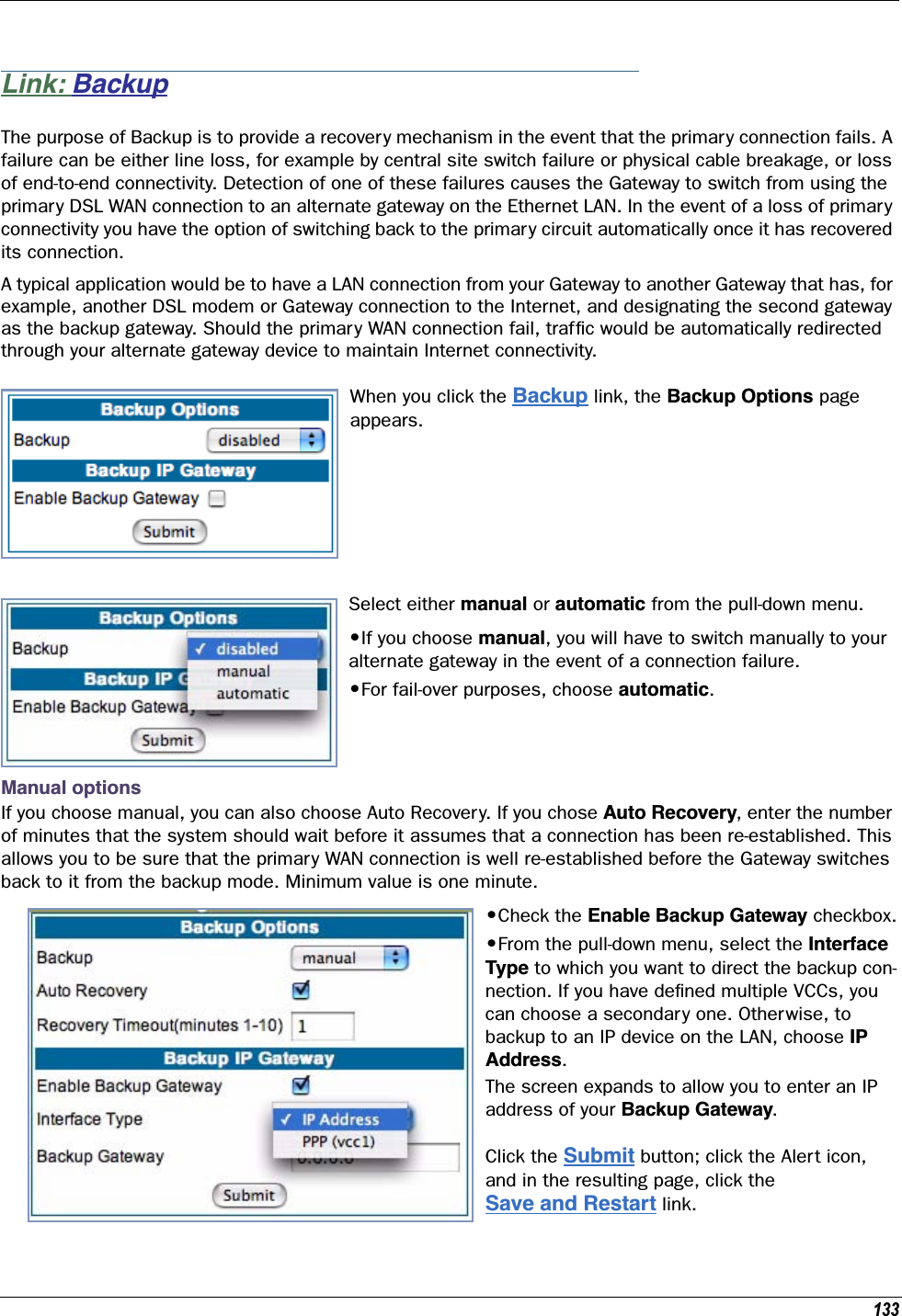
![13 CHAPTER 1 Introduction What’s New in 7.7.4 New in Motorola Netopia® Embedded Software Version 7.7.4 are the following features: • Internet Group Management Protocol (IGMP) Version 3 support. See “IGMP (Internet Group Management Protocol)” on page 100. • TR-101 Support:• Concurrent support for PPPoE and IPoE connections on the WAN. See “WAN” on page 67.• Multiple LAN IP Subnet support. See “LAN” on page 49.• Additional DHCP range support. These ranges are associated with the additional LAN subnets on a 1-to-1 basis.• DHCP option filtering support. Allows DHCP option data to be used to determine the desired DHCP address range. See “DHCP Option Filtering” on page 252.• Support for additional WAN settings to control multicast forwarding as well as if 0.0.0.0 is used as the source address for IGMP packets. See “Advanced:” on page 69.• Support for “unnumbered” interfaces. For IP interfaces, this allows the address to be set to 0 and the DHCP client also to be disabled. See page 71. • PPPoE/DHCP Autosensing. See “WAN” on page 67. • Wireless Multimedia Mode (WMM) support. See “WiFi Multimedia” on page 62. • Firewall: ClearSailing is automatically enabled on all 2200-Series ADSL2+ platforms. (Explicit excep-tions: bonded and VDSL2, 3341, and 3387WG.) See “Firewall” on page 142. • TR-069 Remote device management is automatically enabled by default for 2200-Series Gateways. (Explicit exceptions: bonded and VDSL2, 3341, 3387WG). See “TR-069” on page 322. • Voice-over-IP (VoIP) Support using Session Initiation Protocol (SIP) for supported models. See “VoIP” on page 120 and VoIP CLI “VoIP settings” on page 316. • Support of VLAN ID 0 on the Ethernet WAN and support for setting p-bits on a segment/port basis; inter-VLAN groups. See “VLAN” on page 107 and CLI “VLAN Settings” on page 311. • Backup IP Gateway Support. See “Backup” on page 133 and CLI “Backup IP Gateway Settings” on page 323.Corresponding commands have been added to the Command Line Interface (CLI). See “Command Line Interface” on page 223. • Reset WAN port and wireless counter and CLI command to display individual Ethernet port statistics. See “reset enet [ all ]” on page 231 and “show enet [ all ]” on page 233. •CLI for Motorola Netopia® ATA Remote Management. See “Remote ATA Configuration Commands” on page 243.](https://usermanual.wiki/ARRIS/224762/User-Guide-1097848-Page-13.png)
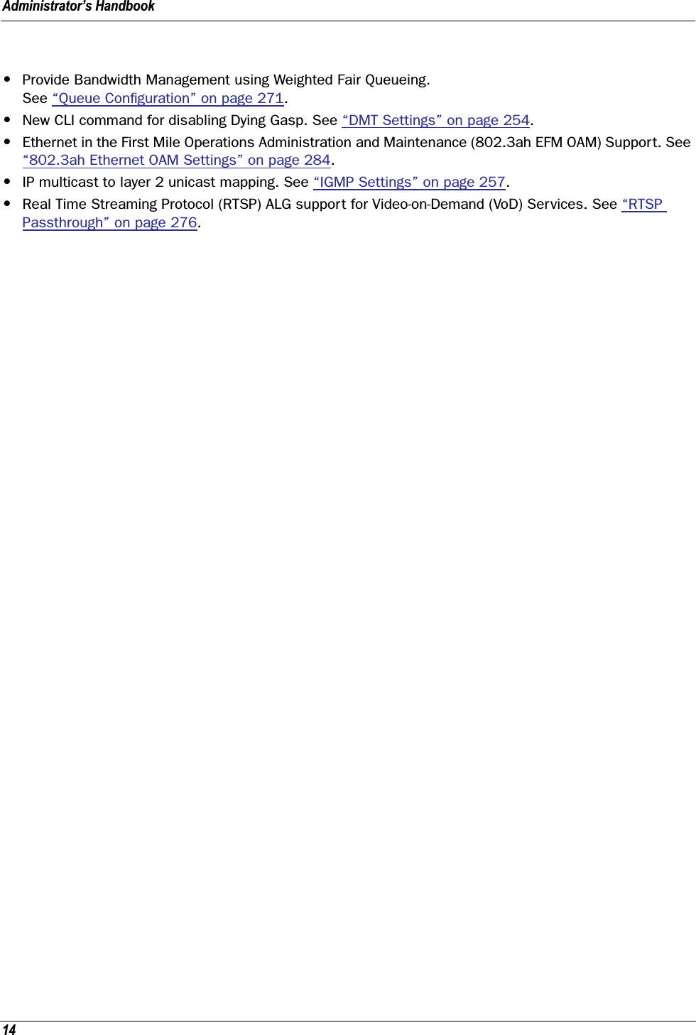
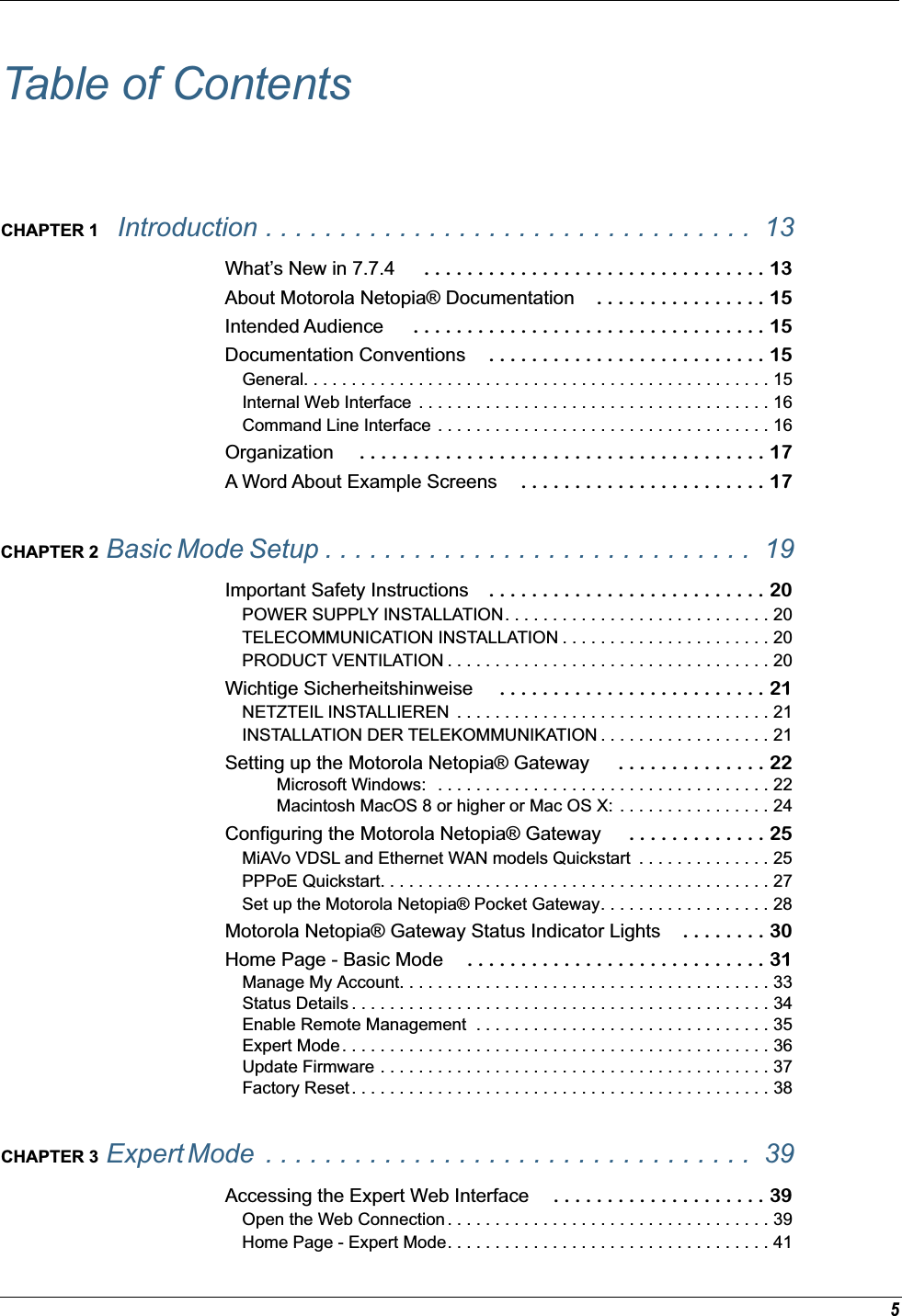
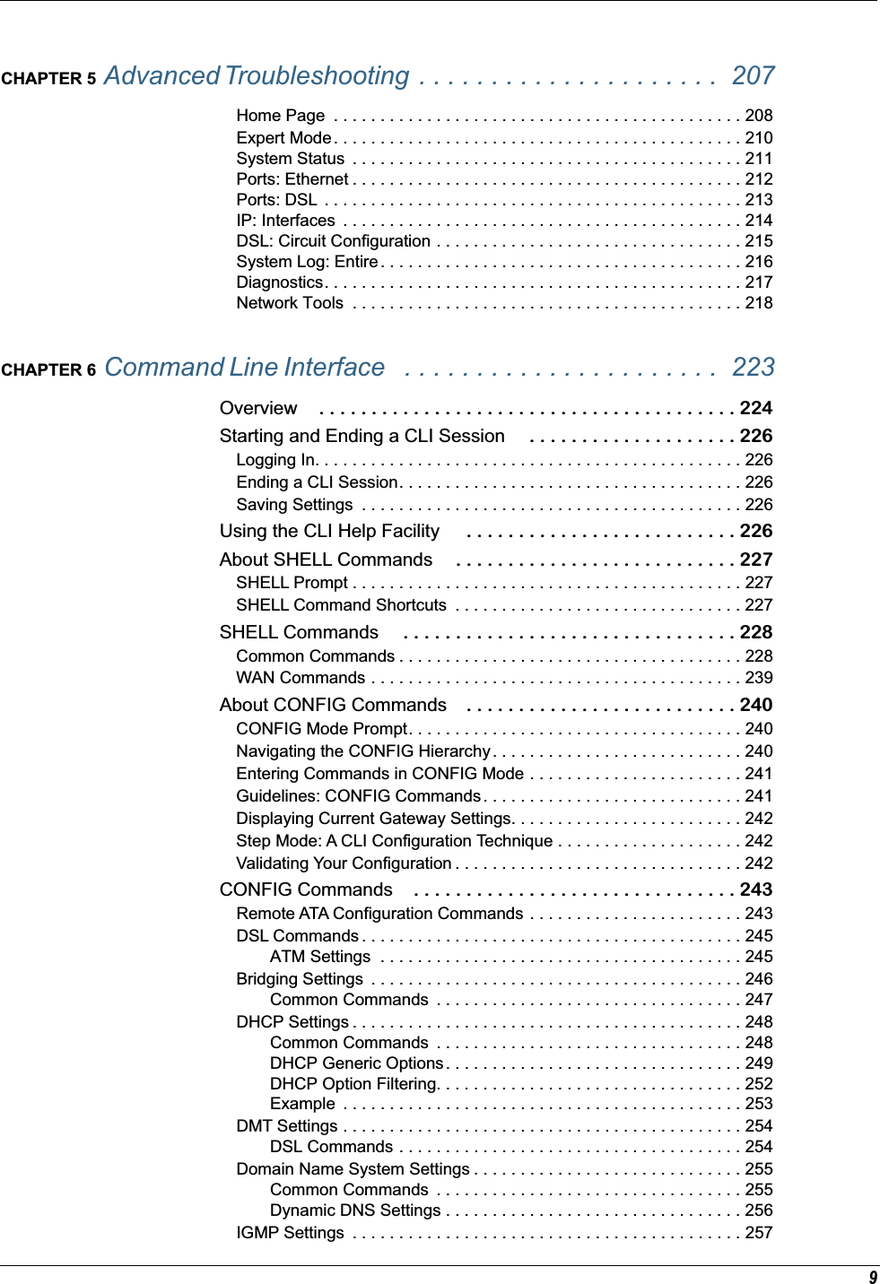
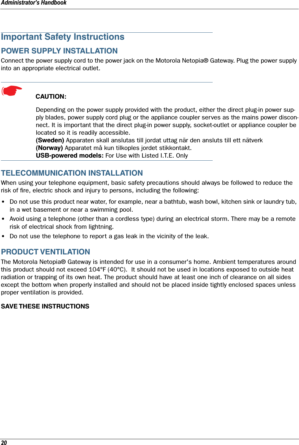
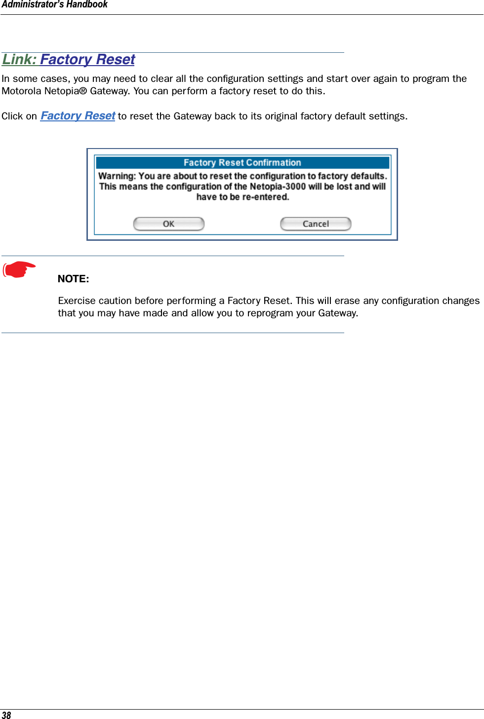
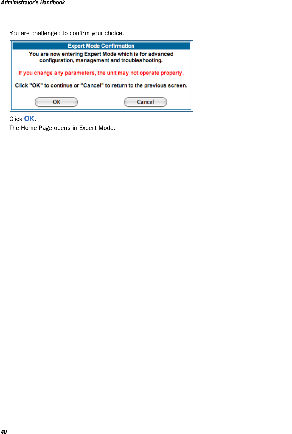
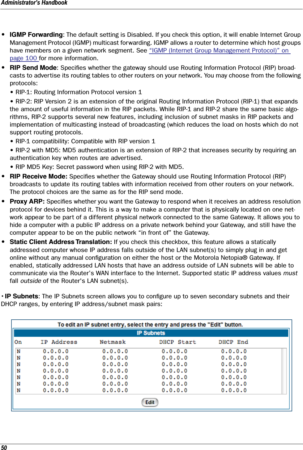
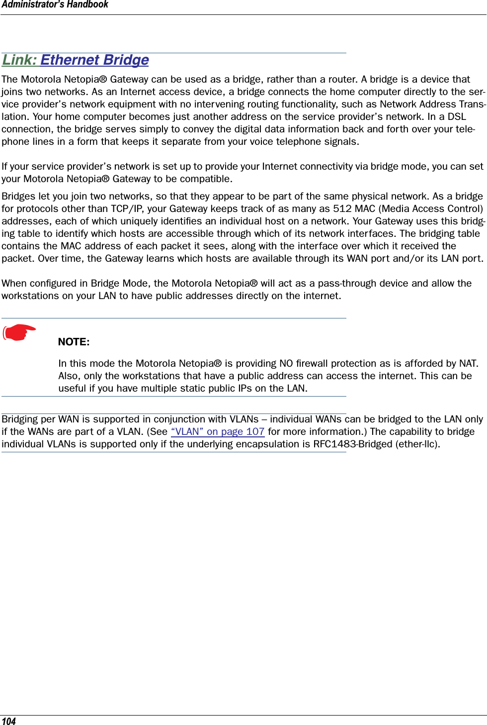
![Administrator’s Handbook16Internal Web InterfaceCommand Line InterfaceSyntax conventions for the Netopia Gateway command line interface are as follows:terminal Computer display textbold terminal User-entered textItalic Italic type indicates the complete titles of manuals.Convention (Graphics) DescriptionDenotes an “excerpt” from a Web page or the visual truncation of a Web pageDenotes an area of emphasis on a Web pageConvention Descriptionstraight ([ ]) brackets in cmd line Optional command arguments curly ({ }) brackets, with values sep-arated with vertical bars (|).Alternative values for an argument are presented in curly ({ }) brackets, with values separated with vertical bars (|).bold terminal type faceUser-entered textitalic terminal type faceVariables for which you supply your own valuesblue rectangle or linesolid rounded rectangle with an arrow](https://usermanual.wiki/ARRIS/224762/User-Guide-1097848-Page-16.png)

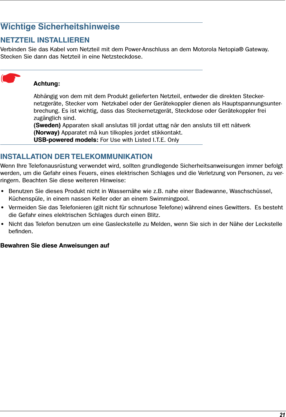
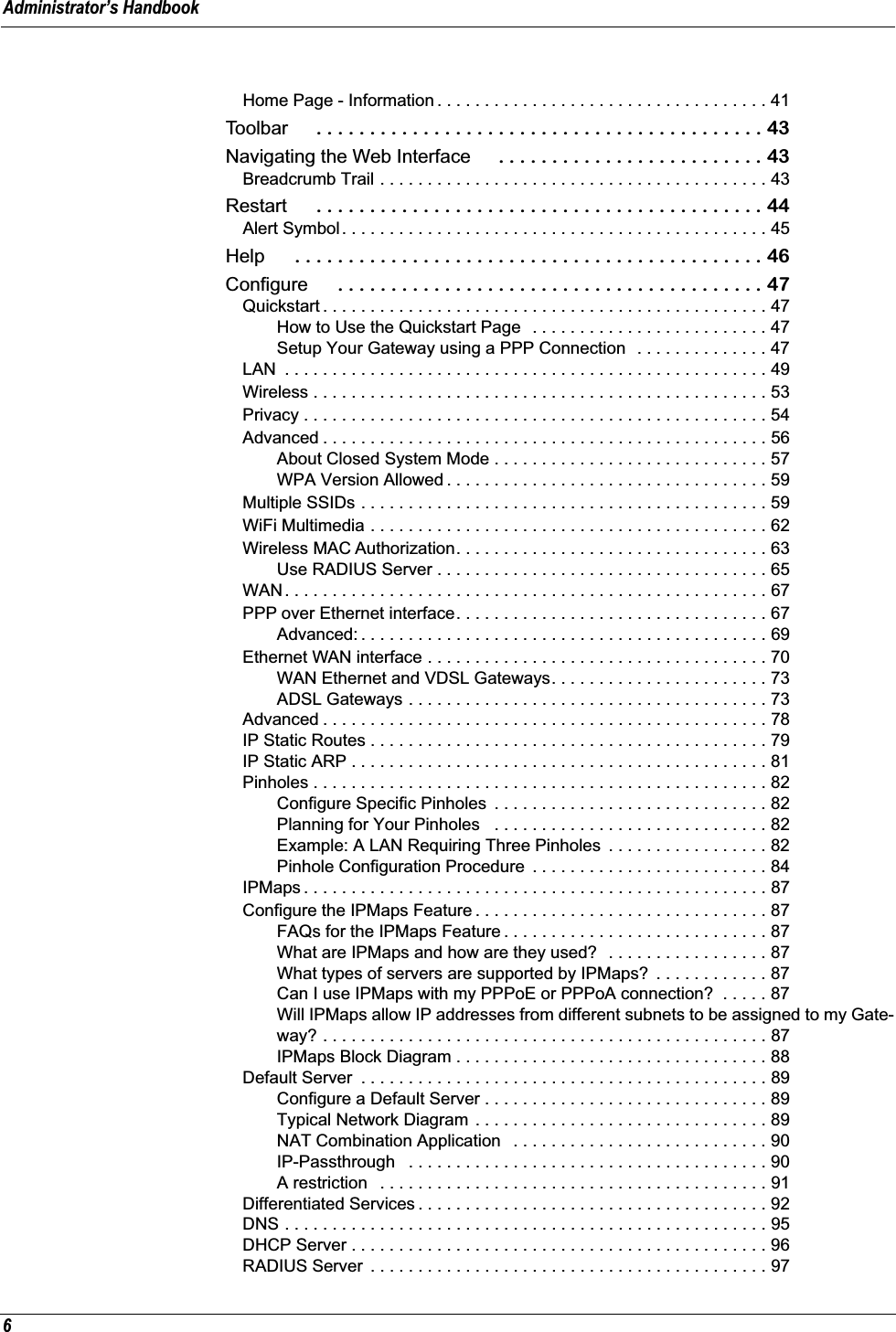
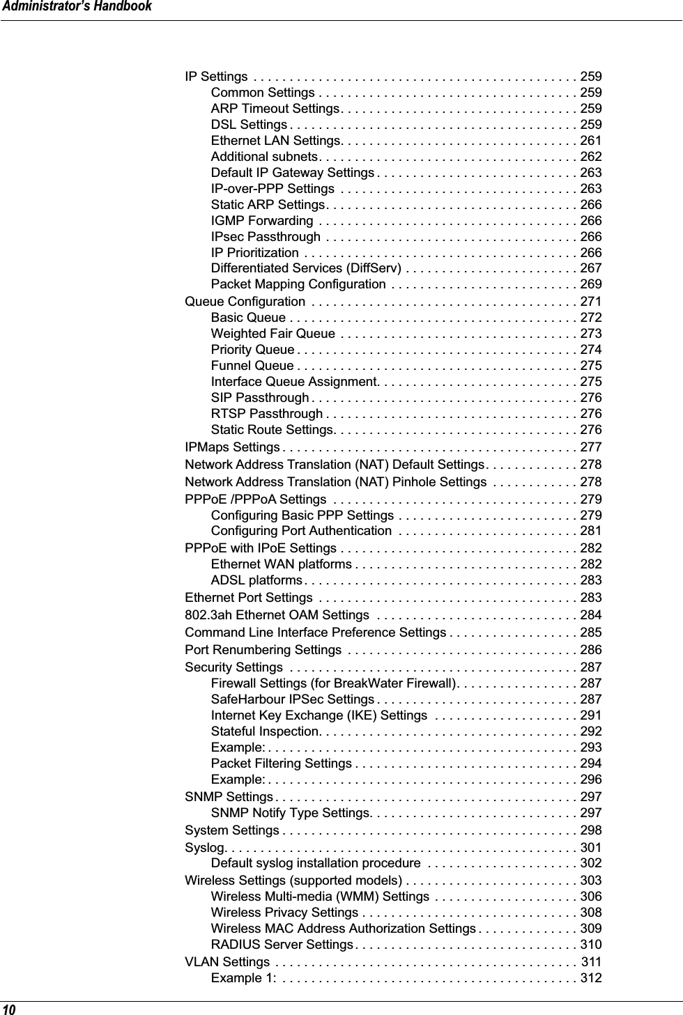
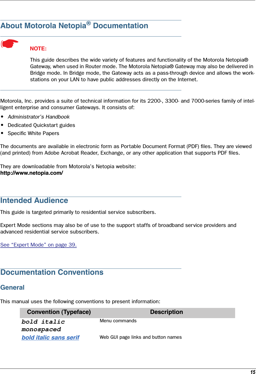
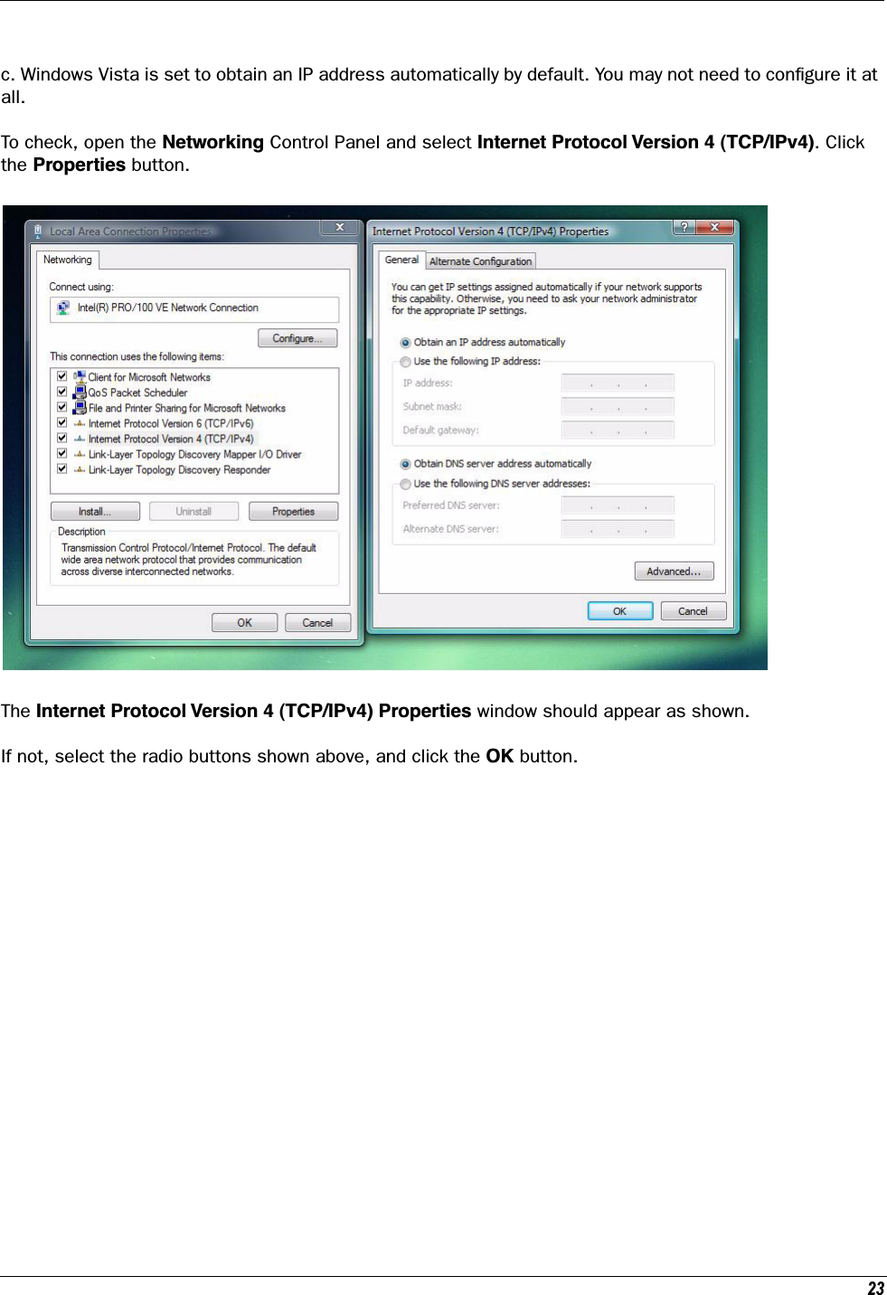
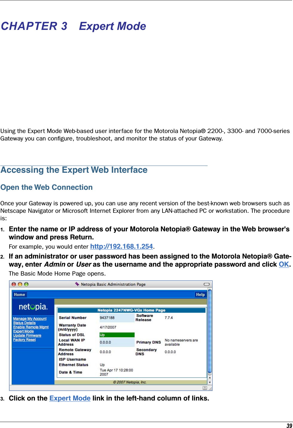
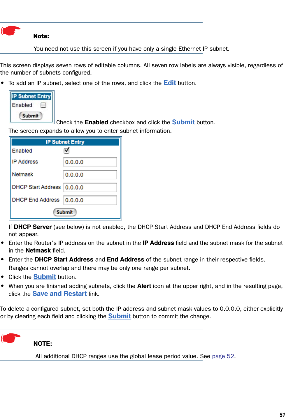
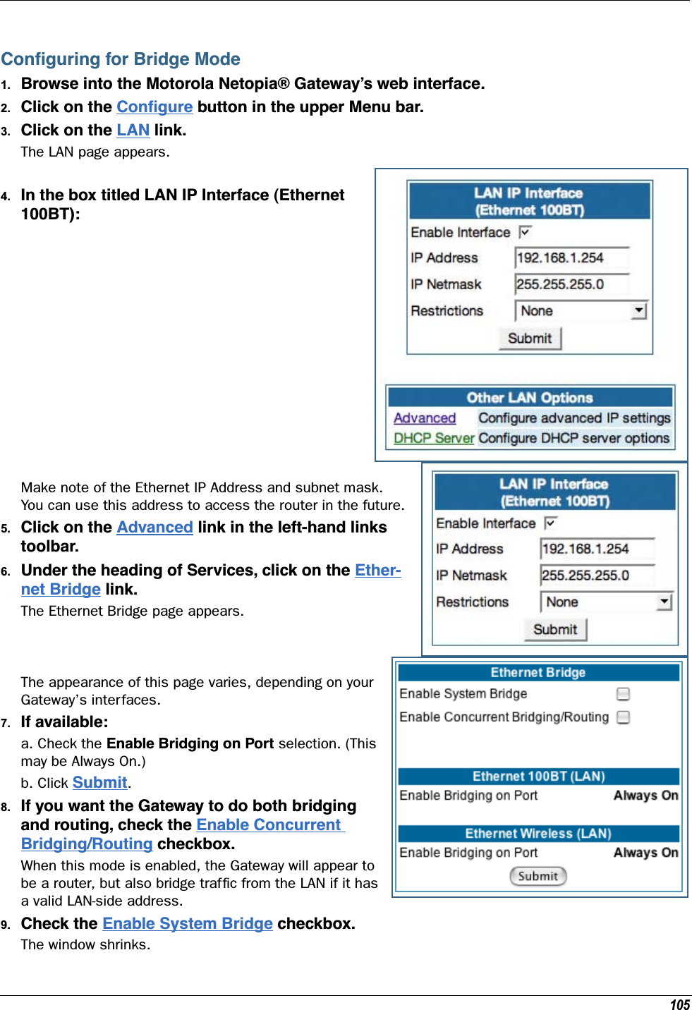
![Administrator’s Handbook22Setting up the Motorola Netopia® GatewayRefer to your Quickstart Guide for instructions on how to connect your Motorola Netopia® gateway to your power source, PC or local area network, and your Internet access point, whether it is a dedicated DSL outlet or a DSL or cable modem. Different Motorola Netopia® Gateway models are supplied for any of these con-nections. Be sure to enable Dynamic Addressing on your PC. Perform the following:Microsoft Windows: Step 1. Navigate to the TCP/IP Properties Control Panel. a. Some Windows versions follow a path like this:Start menu -> Settings -> Control Panel -> Network (or Network and Dial-up Connections -> Local Area Connection -> Properties) -> TCP/IP [your_network_card] or Internet Protocol [TCP/IP] -> Properties b. Some Windows versions follow a path like this:Start menu -> Con-trol Panel -> Net-work and Internet Connections -> Net-work Connections -> Local Area Connec-tion -> Properties -> Internet Protocol [TCP/IP] -> Proper-ties](https://usermanual.wiki/ARRIS/224762/User-Guide-1097848-Page-22.png)


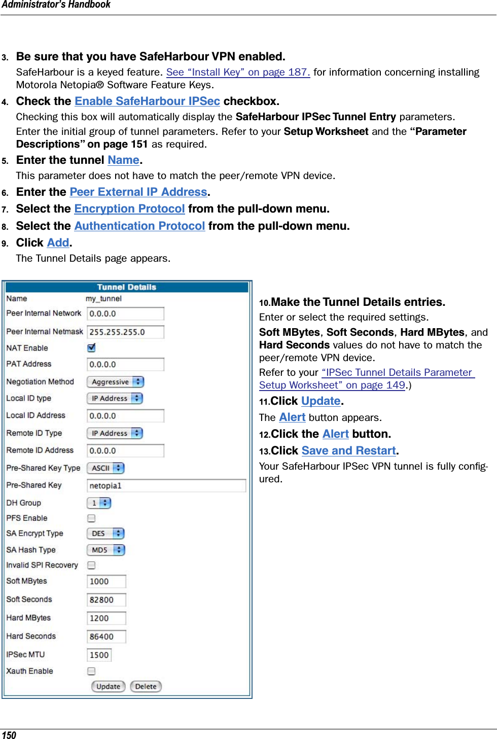


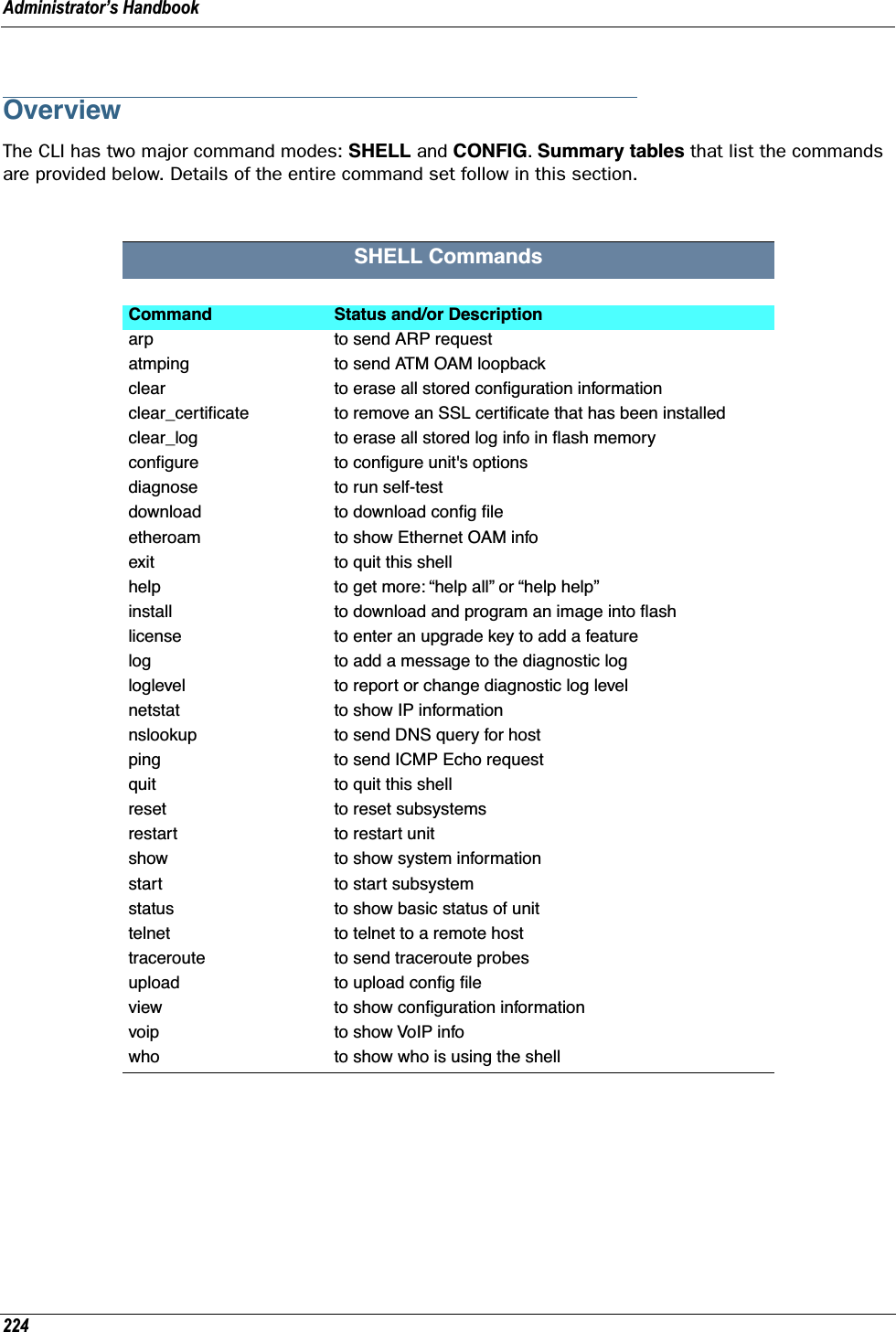
![Administrator’s Handbook228SHELL CommandsCommon Commandsarp nnn.nnn.nnn.nnnSends an Address Resolution Protocol (ARP) request to match the nnn.nnn.nnn.nnn IP address to an Ethernet hardware address.clear [yes]Clears the configuration settings in a Motorola Netopia® Gateway. If you do not use the optional yes qual-ifier, you are prompted to confirm the clear command.clear_certificateRemoves an SSL certificate that has been installed.clear_logErases the log information stored in flash if persistent logging is enabled.configurePuts the command line interface into Configure mode, which lets you configure your Motorola Netopia® Gateway with Config commands. Config commands are described starting on page 225. diagnoseRuns a diagnostic utility to conduct a series of internal checks and loopback tests to verify network connec-tivity over each interface on your Motorola Netopia® Gateway. The console displays the results of each test as the diagnostic utility runs. If one test is dependent on another, the diagnostic utility indents its entry in the console window. For example, the diagnostic utility indents the Check IP connect to Ethernet (LAN) entry, since that test will not run if the Check Ethernet LAN Connect test fails. Each test generates one of the following result codes:download [server_address ] [filename] [confirm]This command installs a file of configuration parameters into the Motorola Netopia® Gateway from a TFTP (Trivial File Transfer Protocol) server. The TFTP server must be accessible on your Ethernet network.CODE DescriptionPASS The test was successful.FAIL The test was unsuccessful.SKIPPED The test was skipped because a test on which it depended failed, or because the test did not apply to your particular setup or model.PENDING The test timed out without producing a result. Try running the test again.](https://usermanual.wiki/ARRIS/224762/User-Guide-1097848-Page-228.png)
![229You can include one or more of the following arguments with the download command. If you omit argu-ments, the console prompts you for this information.•The server_address argument identifies the IP address of the TFTP server from which you want to copy the Motorola Netopia® Gateway configuration file. •The filename argument identifies the path and name of the configuration file on the TFTP server. •If you include the optional confirm keyword, the download begins as soon as all information is entered.You can also download an SSL certificate file from a trusted Certification Authority (CA), on platforms that support SSL, as follows:download [-cert] [server_address ] [filename] [confirm]install [server_address] [filename] [confirm](Not supported on model 3342/3352)Downloads a new version of the Motorola Netopia® Gateway operating software from a TFTP (Trivial File Transfer Protocol) server, validates the software image, and programs the image into the Motorola Neto-pia® Gateway memory. After you install new operating software, you must restart the Motorola Netopia® Gateway.The server_address argument identifies the IP address of the TFTP server on which your Motorola Neto-pia® Gateway operating software is stored. The filename argument identifies the path and name of the operating software file on the TFTP server.If you include the optional keyword confirm, you will not be prompted to confirm whether or not you want to perform the operation.license [key]This command installs a software upgrade key. An upgrade key is a purchased item, based on the serial number of the gateway.log message_stringAdds the message in the message_string argument to the Motorola Netopia® Gateway diagnostic log.loglevel [level] Displays or modifies the types of log messages you want the Motorola Netopia® Gateway to record. If you enter the loglevel command without the optional level argument, the command line interface dis-plays the current log level setting. You can enter the loglevel command with the level argument to specify the types of diagnostic mes-sages you want to record. All messages with a level number equal to or greater than the level you specify are recorded. For example, if you specify loglevel 3, the diagnostic log will retain high-level informational messages (level 3), warnings (level 4), and failure messages (level 5).Use the following values for the level argument:](https://usermanual.wiki/ARRIS/224762/User-Guide-1097848-Page-229.png)
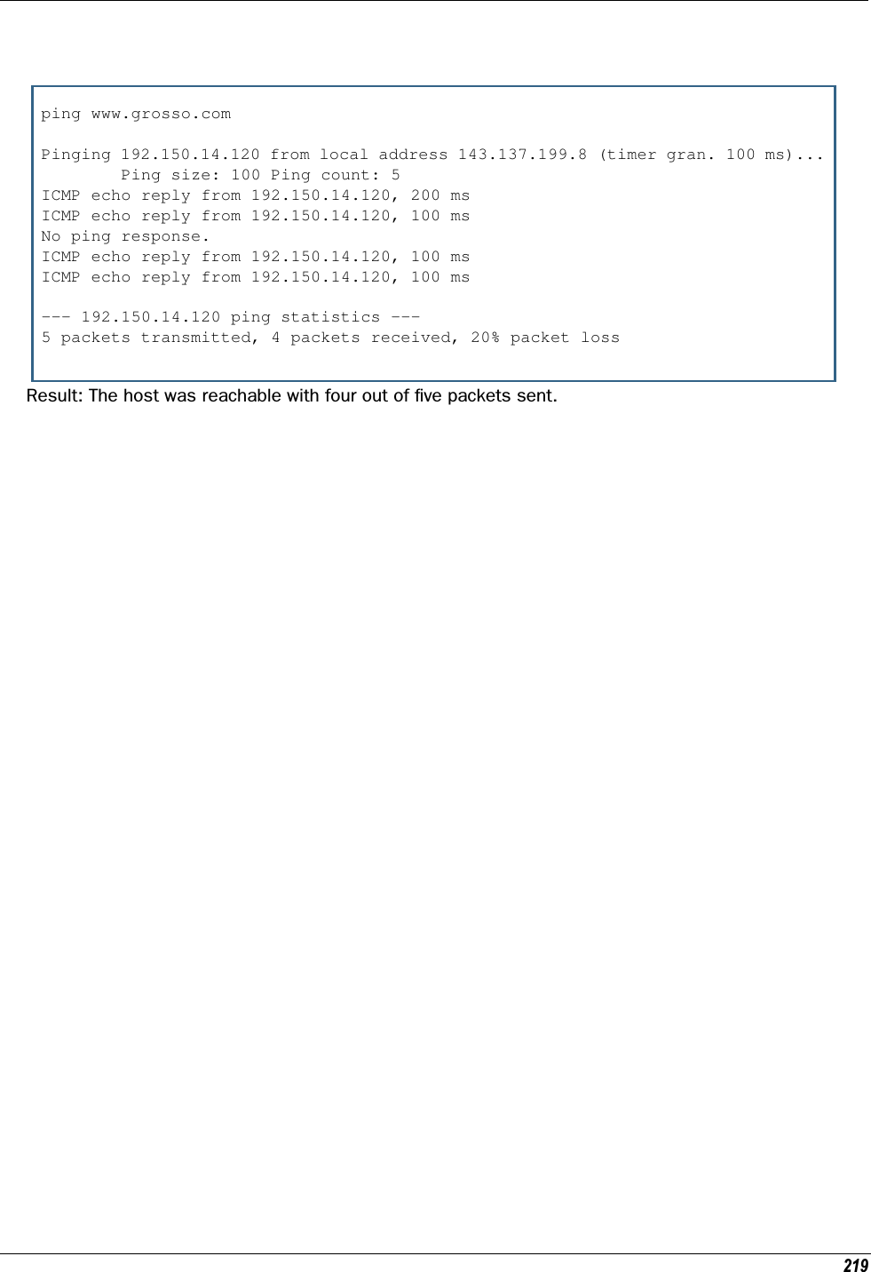
![Administrator’s Handbook230•1 or low – Low-level informational messages or greater; includes trivial status messages.•2 or medium – Medium-level informational messages or greater; includes status messages that can help monitor network traffic.•3 or high – High-level informational messages or greater; includes status messages that may be signif-icant but do not constitute errors.•4 or warning – Warnings or greater; includes recoverable error conditions and useful operator infor-mation.•5 or failure – Failures; includes messages describing error conditions that may not be recover-able. netstat -i Displays the IP interfaces for your Motorola Netopia® Gateway.netstat -r Displays the IP routes stored in your Motorola Netopia® Gateway.nslookup { hostname | ip_address }Performs a domain name system lookup for a specified host.•The hostname argument is the name of the host for which you want DNS information; for example, nslookup klaatu.•The ip_address argument is the IP address, in dotted decimal notation, of the device for which you want DNS information.ping [-s size] [-c count]{ hostname | ip_address }Causes the Motorola Netopia® Gateway to issue a series of ICMP Echo requests for the device with the specified name or IP address. •The hostname argument is the name of the device you want to ping; for example, ping ftp.neto-pia.com.•The ip_address argument is the IP address, in dotted decimal notation, of the device you want to locate. If a host using the specified name or IP address is active, it returns one or more ICMP Echo replies, confirming that it is accessible from your network.•The -s size argument lets you specify the size of the ICMP packet.•The -c count argument lets you specify the number of ICMP packets generated for the ping request. Values greater than 250 are truncated to 250.You can use the ping command to determine whether a hostname or IP address is already in use on your network. You cannot use the ping command to ping the Motorola Netopia® Gateway’s own IP address.quit Exits the Motorola Netopia® Gateway command line interface.](https://usermanual.wiki/ARRIS/224762/User-Guide-1097848-Page-230.png)
![231reset arp Clears the Address Resolution Protocol (ARP) cache on your unit.reset atmResets the Asynchronous Transfer Mode (ATM) statistics.reset cdmodeThis command will set up one boot flag so that the next time a 3342N/3352N restarts or reboots (power cycle), the Gateway will boot into CD-ROM mode instead of Gateway mode.This command is only for the 3342N/3352N. If the Gateway is not a 3342N/3352N this command does nothing but returns the message: "CD mode is not supported on this platform."reset crash Clears crash-dump information, which identifies the contents of the Motorola Netopia® Gateway registers at the point of system malfunction.reset dhcp serverClears the DHCP lease table in the Motorola Netopia® Gateway.reset diffservResets the Differentiated Services (diffserv) statistics.reset enet [ all ]Resets Ethernet statistics to zero. Resets individual LAN switch port statistics as well as wireless and WAN Ethernet statistics (where applicable).reset heartbeatRestarts the heartbeat sequence.reset ipmapClears the IPMap table (NAT).reset logRewinds the diagnostic log display to the top of the existing Motorola Netopia® Gateway diagnostic log. The reset log command does not clear the diagnostic log. The next show log command will display infor-mation from the beginning of the log file.](https://usermanual.wiki/ARRIS/224762/User-Guide-1097848-Page-231.png)
![Administrator’s Handbook232reset security-logClears the security monitoring log to make room to capture new entries. reset wan-users [all | ip-address]This function disconnects the specified WAN User to allow for other users to access the WAN. This function is only available if the number of WAN Users is restricted and NAT is on. Use the all parameter to discon-nect all users. If you logon as Admin you can disconnect any or all users. If you logon as User, you can only disconnect yourself.reset wanThis function resets WAN interface statistics.reset wepkeysThis function allows you to force your wireless WEP key settings back to the default values, if there are default values. For example, on some models, the WEP keys are based on the serial number. This allows you to get back those default settings if you have changed them without the need to reset the entire config-uration of the unit.restart [seconds]Restarts your Motorola Netopia® Gateway. If you include the optional seconds argument, your Motorola Netopia® Gateway will restart when the specified number of seconds have elapsed. You must enter the complete restart command to initiate a restart.show all-infoDisplays all settings currently configured in the Motorola Netopia® Gateway.show backupDisplays the status of the Backup port, Up or Down, and reports the current port in use.show bridge interfacesDisplays bridge interfaces maintained by the Motorola Netopia® Gateway.show bridge tableDisplays the bridging table maintained by the Motorola Netopia® Gateway.show configDumps the Motorola Netopia® Gateway’s configuration script just as the script command does in config mode.](https://usermanual.wiki/ARRIS/224762/User-Guide-1097848-Page-232.png)
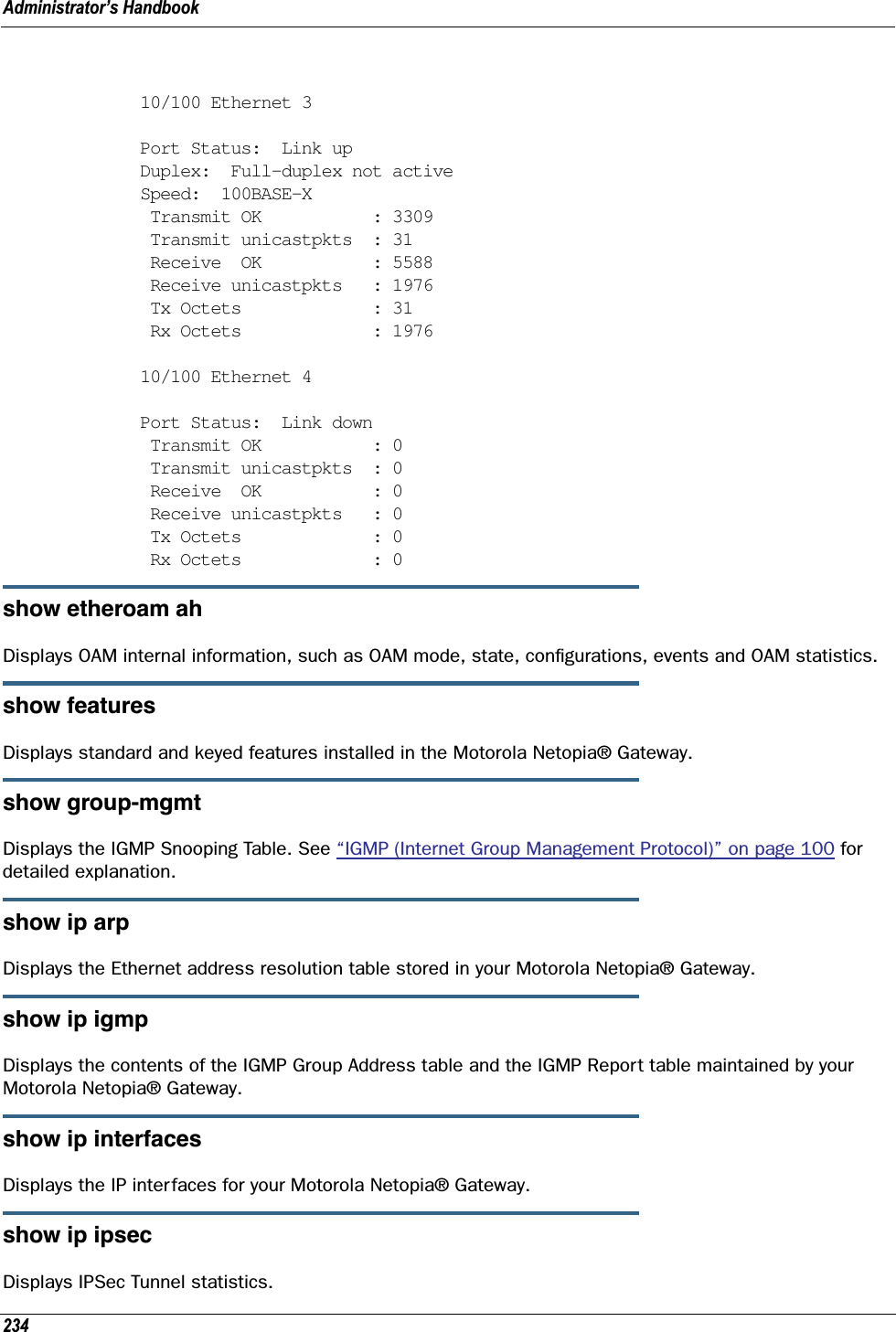
![233show crashDisplays the most recent crash information, if any, for your Motorola Netopia® Gateway.show dhcp agentDisplays DHCP relay-agent leases.show dhcp server leasesDisplays the DHCP leases stored in RAM by your Motorola Netopia® Gateway.show diffservDisplays the Differentiated Services and QoS values configured in the Motorola Netopia® Gateway.show dslf device-associationDisplays LAN devices that conform with the TR111 Gateway requirement. It displays - IP Address, Manufac-ture OUI and Serial number.show enet [ all ]Displays Ethernet inter face statistics maintained by the Motorola Netopia® Gateway. Beginning with Firm-ware Version 7.7, supports display of individual LAN switch port statistics as well as WAN Ethernet statis-tics (where applicable).Example:show enet status all10/100 Ethernet 1Port Status: Link down Transmit OK : 0 Transmit unicastpkts : 0 Receive OK : 0 Receive unicastpkts : 0 Tx Octets : 0 Rx Octets : 010/100 Ethernet 2Port Status: Link down Transmit OK : 0 Transmit unicastpkts : 0 Receive OK : 0 Receive unicastpkts : 0 Tx Octets : 0 Rx Octets : 0](https://usermanual.wiki/ARRIS/224762/User-Guide-1097848-Page-233.png)
![235show ip firewallDisplays firewall statistics.show ip lan-discoveryDisplays the LAN Host Discovery Table of hosts on the wired or wireless LAN, and whether or not they are currently online.show ip routesDisplays the IP routes stored in your Motorola Netopia® Gateway.show ip state-inspDisplays whether stateful inspection is enabled on an interface or not, exposed addresses and blocked packet statistics because of stateful inspection.show ipmapDisplays IPMap table (NAT).show logDisplays blocks of information from the Motorola Netopia® Gateway diagnostic log. To see the entire log, you can repeat the show log command or you can enter show log all.show memory [all]Displays memory usage information for your Motorola Netopia® Gateway. If you include the optional all argument, your Motorola Netopia® Gateway will display a more detailed set of memory statistics.show pppoeDisplays status information for each PPPoE socket, such as the socket state, service names, and host ID values.show rtspDisplays RTSP ALG session activity data.show security-logDisplays blocks of information from the Motorola Netopia® Gateway security log.](https://usermanual.wiki/ARRIS/224762/User-Guide-1097848-Page-235.png)
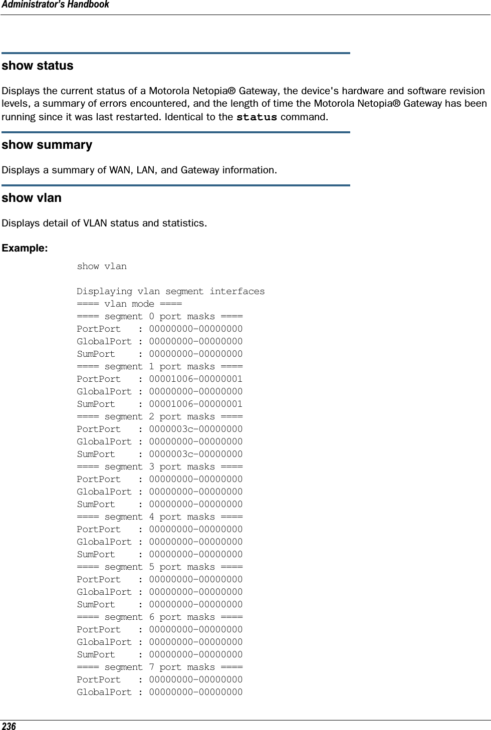
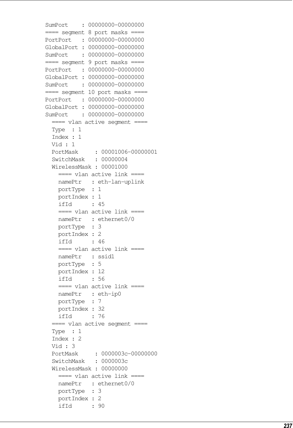
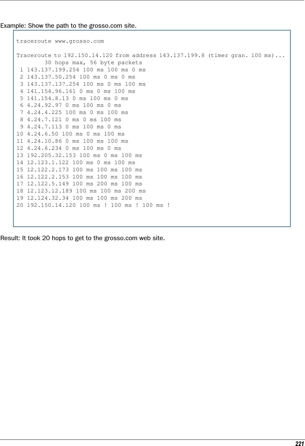
![Administrator’s Handbook238 ==== vlan active link ==== namePtr : ethernet0/1 portType : 3 portIndex : 3 ifId : 91 ==== vlan active link ==== namePtr : ethernet0/2 portType : 3 portIndex : 4 ifId : 92 ==== vlan active link ==== namePtr : ethernet0/3 portType : 3 portIndex : 5 ifId : 93show wireless [all]Shows wireless status and statistics.show wireless clients [ MAC_address ]Displays details on connected clients, or more details on a particular client if the MAC address is added as an argument.telnet { hostname | ip_address } [port] Lets you open a telnet connection to the specified host through your Motorola Netopia® Gateway.•The hostname argument is the name of the device to which you want to connect; for example, telnet ftp.netopia.com.•The ip_address argument is the IP address, in dotted decimal notation, of the device to which you want to connect.•The port argument is the number of t he port over which you want to open a telnet session.traceroute ( ip_address | hostname )Traces the routing path to an IP destination.upload [server_address] [filename] [confirm]Copies the current configuration settings of the Motorola Netopia® Gateway to a TFTP (Trivial File Transfer Protocol) server. The TFTP server must be accessible on your Ethernet network. The server_address argument identifies the IP address of the TFTP server on which you want to store the Motorola Netopia® Gateway settings. The filename argument identifies the path and name of the configuration file on the TFTP server. If you include the optional confirm keyword, you will not be prompted to confirm whether or not you want to perform the operation.view configDumps the Motorola Netopia® Gateway’s configuration just as the view command does in config mode.](https://usermanual.wiki/ARRIS/224762/User-Guide-1097848-Page-238.png)
![239who Displays the names of the current shell and PPP users. WAN Commandsatmping vccn [ segment | end-to-end ]Lets you check the ATM connection reachability and network connectivity. This command sends five Opera-tions, Administration, and Maintenance (OAM) loopback calls to the specified vpi/vci destination. There is a five second total timeout interval.Use the segment argument to ping a neighbor switch.Use the end-to-end argument to ping a remote end node.reset dhcp client release [ vcc-id ]Releases the DHCP lease the Motorola Netopia® Gateway is currently using to acquire the IP settings for the specified DSL port. The vcc-id identifier is an “index” letter in the range B-I, and does not directly map to the VCC in use. Enter the reset dhcp client release command without the variable to see the letter assigned to each virtual circuit.reset dhcp client renew [ vcc-id ]Releases the DHCP lease the Motorola Netopia® Gateway is currently using to acquire the IP settings for the specified DSL port. The vcc-id identifier is an “index” letter in the range B-I, and does not directly map to the VCC in use. Enter the reset dhcp client release without the variable to see the letter assigned to each virtual circuit.reset dslResets any open DSL connection.reset ppp vccnResets the point-to-point connection over the specified virtual circuit. This command only applies to virtual circuits that use PPP framing.show atm [all]Displays ATM statistics for the Motorola Netopia® Gateway. The optional all argument displays a more detailed set of ATM statistics.show dsl [ all ]Displays DSL port statistics, such as upstream and downstream connection rates and noise levels.](https://usermanual.wiki/ARRIS/224762/User-Guide-1097848-Page-239.png)
![Administrator’s Handbook240show ppp [{ stats | lcp | ipcp }]Displays information about open PPP links. You can display a subset of the PPP statistics by including an optional stats, lcp, or ipcp argument for the show ppp command.start ppp vccnOpens a PPP link on the specified virtual circuit.About CONFIG CommandsYou reach the configuration mode of the command line interface by typing configure (or any truncation of configure, such as con or config) at the CLI SHELL prompt.CONFIG Mode PromptWhen you are in CONFIG mode, the CLI prompt consists of the name of the Motorola Netopia® Gateway fol-lowed by your current node in the hierarchy and two right angle brackets (>>). For example, when you enter CONFIG mode (by typing config at the SHELL prompt), the Netopia-3000/9437188 (top)>> prompt reminds you that you are at the top of the CONFIG hierarchy. If you move to the ip node in the CON-FIG hierarchy (by typing ip at the CONFIG prompt), the prompt changes to Netopia-3000/9437188 (ip)>> to identify your current location.Some CLI commands are not available until certain conditions are met. For example, you must enable IP for an interface before you can enter IP settings for that interface.Navigating the CONFIG Hierarchy•Moving from CONFIG to SHELL — You can navigate from anywhere in the CONFIG hierarchy back to the SHELL level by entering quit at the CONFIG prompt and pressing RETURN. Netopia-3000/9437188 (top)>> quitNetopia-3000/9437188 >•Moving from top to a subnode — You can navigate from the top node to a subnode by entering the node name (or the significant letters of the node name) at the CONFIG prompt and pressing RETURN. For example, you move to the IP subnode by entering ip and pressing RETURN.Netopia-3000/9437188 (top)>> ipNetopia-3000/9437188 (ip)>>As a shortcut, you can enter the significant letters of the node name in place of the full node name at the CONFIG prompt. The significant characters of a node name are the letters that uniquely identify the node. For example, since no other CONFIG node starts with b, you could enter one letter (“b”) to move to the bridge node.•Jumping down several nodes at once — You can jump down several levels in the CONFIG hierarchy by entering the complete path to a node. •Moving up one node — You can move up through the CONFIG hierarchy one node at a time by entering the up command.](https://usermanual.wiki/ARRIS/224762/User-Guide-1097848-Page-240.png)
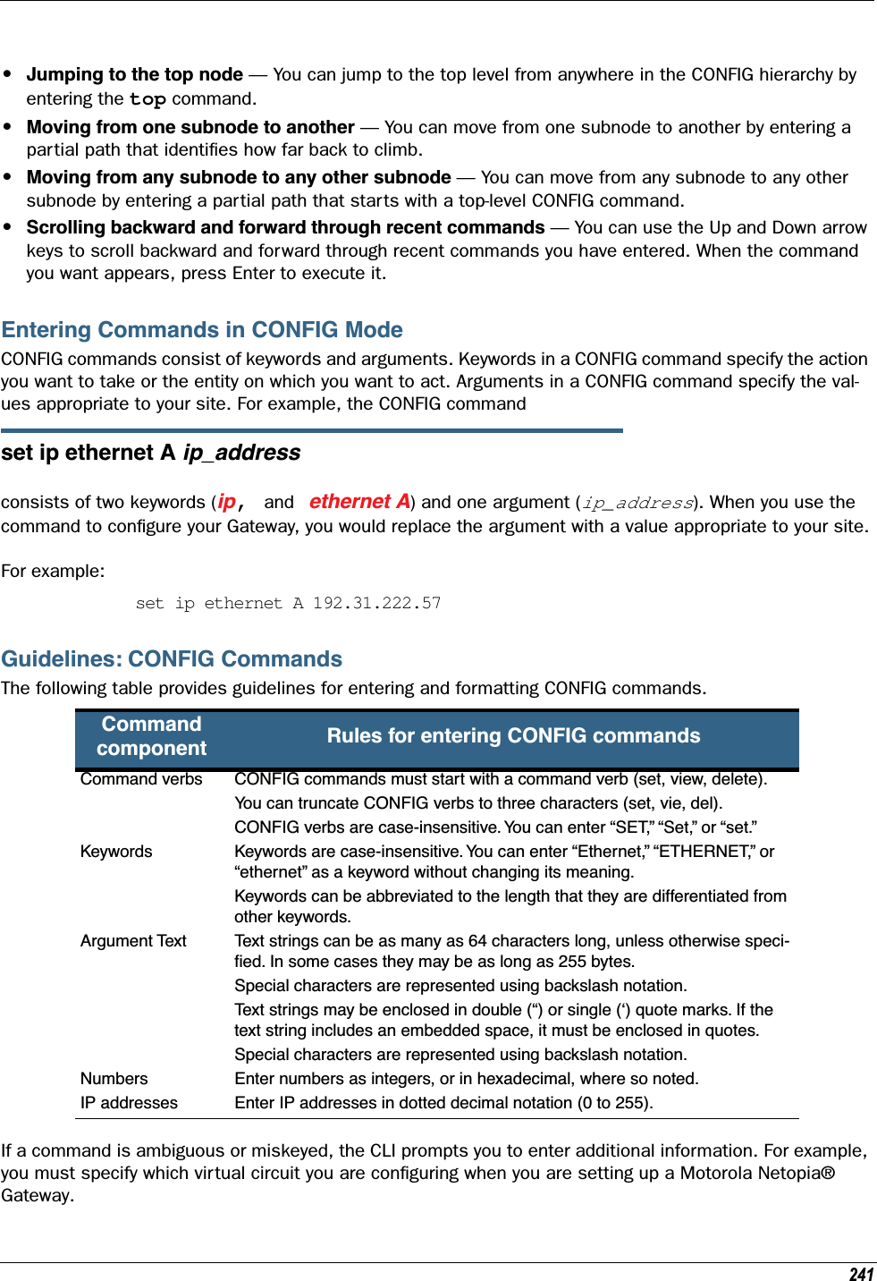
![Administrator’s Handbook242Displaying Current Gateway SettingsYou can use the view command to display the current CONFIG settings for your Motorola Netopia® Gate-way. If you enter the view command at the top level of the CONFIG hierarchy, the CLI displays the settings for all enabled functions. If you enter the view command at an intermediate node, you see settings for that node and its subnodes.Step Mode: A CLI Configuration TechniqueThe Motorola Netopia® Gateway command line interface includes a step mode to automate the process of entering configuration settings. When you use the CONFIG step mode, the command line interface prompts you for all required and optional information. You can then enter the configuration values appropriate for your site without having to enter complete CLI commands.When you are in step mode, the command line interface prompts you to enter required and optional set-tings. If a setting has a default value or a current setting, the command line interface displays the default value for the command in parentheses. If a command has a limited number of acceptable values, those val-ues are presented in brackets, with each value separated by a vertical line. For example, the following CLI step command indicates that the default value is off and that valid entries are limited to on and off.option (off) [on | off]: onYou can accept the default value for a field by pressing the Return key. To use a different value, enter it and press Return.You can enter the CONFIG step mode by entering set from the top node of the CONFIG hierarchy. You can enter step mode for a particular service by entering set service_name. In stepping set mode (press Control-X <Return/Enter> to exit. For example:Netopia-3000/9437188 (top)>> set system...system name (“Netopia-3000/9437188”): Mycroft Diagnostic Level (High): mediumStepping mode ended.Validating Your ConfigurationYou can use the validate CONFIG command to make sure that your configuration settings have been entered correctly. If you use the validate command, the Motorola Netopia® Gateway verifies that all required settings for all services are present and that settings are consistent.Netopia-3000/9437188 (top)>> validateError: Subnet mask is incorrectGlobal Validation did not pass inspection!You can use the validate command to verify your configuration settings at any time. Your Motorola Neto-pia® Gateway automatically validates your configuration any time you save a modified configuration.](https://usermanual.wiki/ARRIS/224762/User-Guide-1097848-Page-242.png)
![243CONFIG CommandsThis section describes the keywords and arguments for the various CONFIG commands.Remote ATA Configuration CommandsMotorola Netopia® firmware supports configuration of a maximum of four Motorola Netopia® ATA profiles, which are stored in the Gateway’s configuration database. When a Motorola Netopia® ATA is discovered, the Gateway compares the MAC address of the ATA with one of the existing profiles stored in the database. If there is a match, the configuration is downloaded to the Motorola Netopia® ATA, and the ATA is restarted. Once the Motorola Netopia® ATA is restarted, it comes up with the newly downloaded configuration.set ata profile [ 0... 3 ] ata-option [ on | off ]Enables or disables the remote ATA configuration option for the specified ATA configuration profile to be stored in the Gateway.set ata profile [ 0... 3 ] ata-mac-addr MAC_addrSpecifies the MAC address of the ATA for the specified configuration profile.set ata profile [ 0... 3 ] ata-qos-enable [ on | off ]Enables or disables QoS for the specified profile.set ata profile [ 0... 3 ] ata-dhcpc-enable [ on | off ]Enables or disables DHCP client service for the specified profile.set ata profile [ 0... 3 ] ata-dhcpc-hostname stringSpecifies a DHCP client hostname for the specified profile.set ata profile [ 0... 3 ] ata-dhcpc-vid-enable [ off | on ]Enables or disables a DHCP client vendor ID for the specified profile.set ata profile [ 0... 3 ] ata-dhcpc-vid stringSpecifies a vendor ID for the specified profile when ata-dhcpc-vid-enable is on.set ata profile [ 0... 3 ] ata-static-wan-ip ip_addrSpecifies a static WAN IP address for the specified profile.set ata profile [ 0... 3 ] ata-static-wan-subnet-mask subnet_maskSpecifies a static WAN IP subnet mask for the specified profile.](https://usermanual.wiki/ARRIS/224762/User-Guide-1097848-Page-243.png)
![Administrator’s Handbook244set ata profile [ 0... 3 ] ata-static-wan-gateway ip_addrSpecifies a static gateway WAN IP address for the specified profile.set ata profile [ 0... 3 ] ata-proxy-server ip_addrSpecifies a SIP proxy server hostname or IP address for the specified profile.set ata profile [ 0... 3 ] ata-proxy-port portSpecifies a SIP proxy server port, typically 5060, for the specified profile.set ata profile [ 0... 3 ] ata-registrar-server ip_addrSpecifies a registrar server hostname or IP address for the specified profile.set ata profile [ 0... 3 ] ata-registrar-port portSpecifies a registrar server port, typically 5060, for the specified profile.set ata profile [ 0... 3 ] ata-outproxy-server ip_addrSpecifies an outbound proxy server hostname or IP address for the specified profile.set ata profile [ 0... 3 ] ata-outproxy-port portSpecifies an outbound proxy server port, typically 5060, for the specified profile.set ata profile [ 0... 3 ] ata-auth-id valueSpecifies an authorization ID for the specified profile.set ata profile [ 0... 3 ] ata-user-name stringSpecifies the ISP-supplied user name for the specified profile.set ata profile [ 0... 3 ] ata-user-display-name stringSpecifies the a user “display” or “screen” name for the specified profile.set ata profile [ 0... 3 ] ata-user-password stringSpecifies the user password for the specified profile.](https://usermanual.wiki/ARRIS/224762/User-Guide-1097848-Page-244.png)
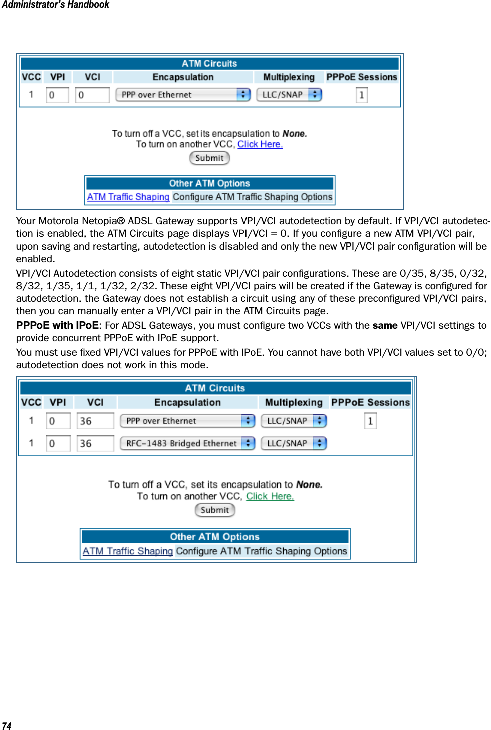
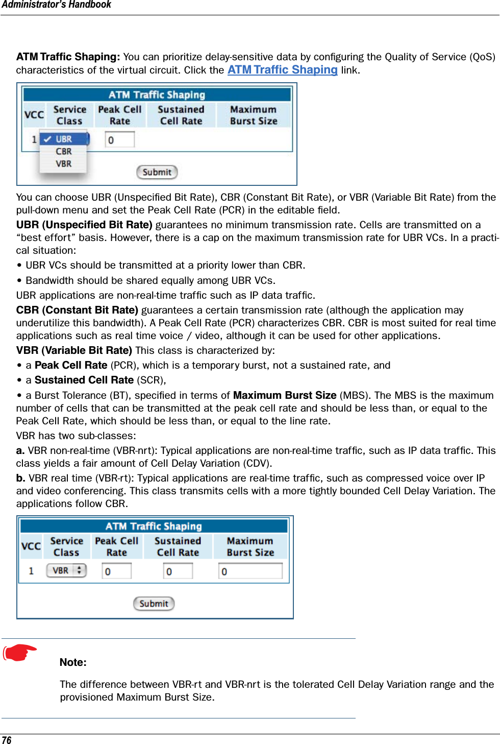
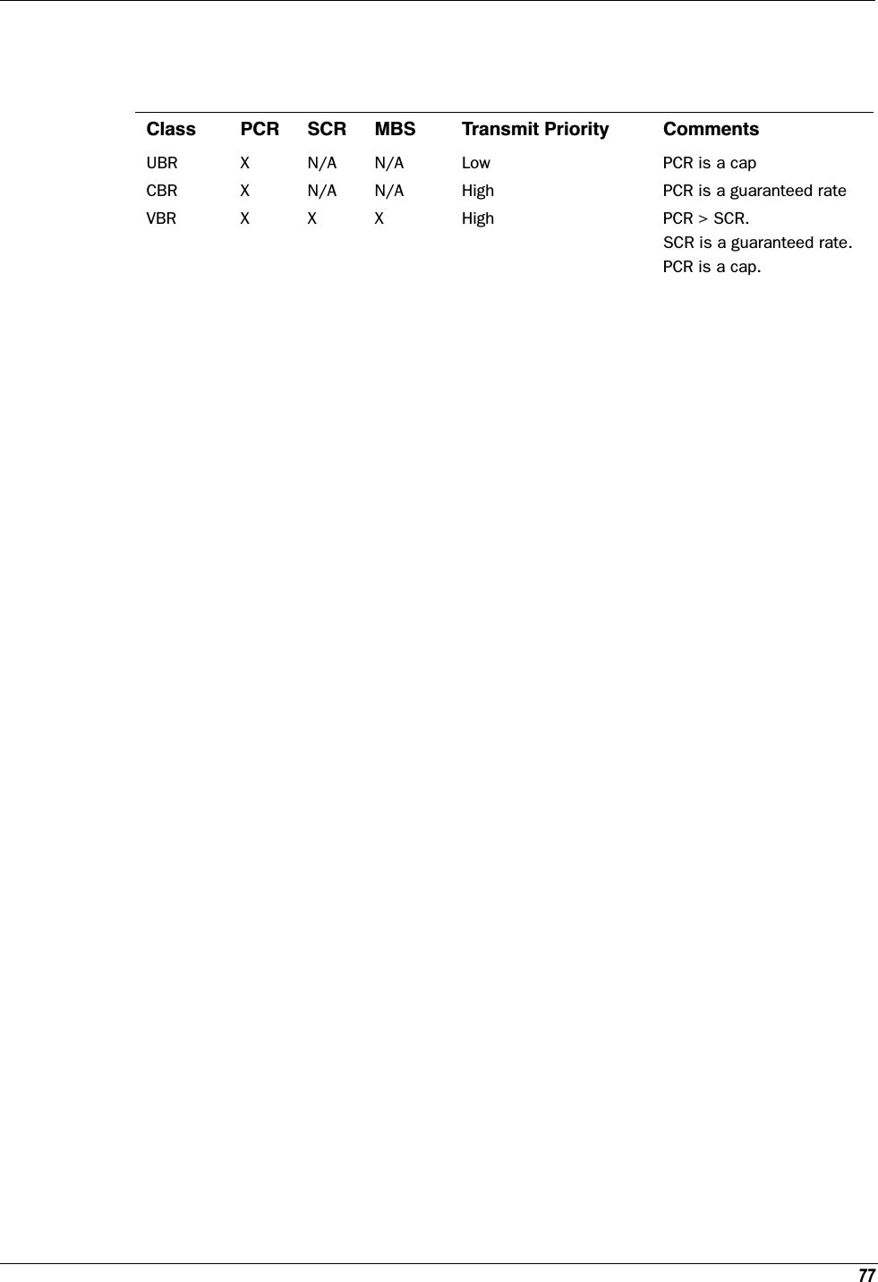
![245DSL CommandsATM Settings. You can use the CLI to set up each ATM virtual circuit. set atm option {on | off } Enables the WAN interface of the Motorola Netopia® Gateway to be configured using the Asynchronous Transfer Mode (ATM) protocol.set atm [vcc n] option {on | off } Selects the virtual circuit for which further parameters are set. Up to eight VCCs are supported; the maxi-mum number is dependent on your Motorola Netopia® Operating System tier and the capabilities that your Service Provider offers.set atm [vcc n] qos service-class { cbr | ubr | vbr }Sets the Quality of Service class for the specified virtual circuit – Constant (cbr), Unspecified (ubr), or Vari-able (vbr) Bit Rate. •ubr: No configuration is needed for UBR VCs. Leave the default value 0 (maximum line rate).•cbr: One parameter is required for CBR VCs. Enter the Peak Cell Rate that applies to the VC. This value should be between 1 and the line rate. You set this value according to specifications defined by your ser-vice provider.•vbr: Three parameters are required for VBR VCs. Enter the Peak Cell Rate, the Sustained Cell Rate, and the Maximum Burst Size that apply to the VC. You set these values according to specifications defined by your service provider.set atm [vcc n] qos peak-cell-rate { 1 ...n }If QoS class is set to cbr or vbr then specify the peak-cell-rate that should apply to the specified virtual circuit. This value should be between 1 and the line rate.The Peak Cell Rate (PCR) should be set to the maximum rate a PVC can oversubscribe its Sustained Cell Rate (SCR). The Peak Cell Rate (see below) must be less than, or equal to the raw WAN (DSL) bit rate. The Maximum Burst Size (MBS) is the number of cells that can be sent at the PCR rate, after which the PVC must fall back to the SCR rate.set atm [vcc n] qos sustained-cell-rate { 1 ...n }If QoS class is set to vbr, then specify the sustained-cell-rate that should apply to the specified virtual cir-cuit. This value should be less than, or equal to the Peak Cell Rate, which should be less than, or equal to the line rate.set atm [vcc n] qos max-burst-size { 1 ...n }If QoS class is set to vbr then specify the max-burst-size that should apply to the specified virtual circuit. This value is the maximum number of cells that can be transmitted at the Peak Cell Rate after which the ATM VC transmission rate must drop to the Sustained Cell Rate.](https://usermanual.wiki/ARRIS/224762/User-Guide-1097848-Page-245.png)
![Administrator’s Handbook246set atm [vcc n] vpi { 0 ... 255 } Select the virtual path identifier (vpi) for VCC n.Your Service Provider will indicate the required vpi number.set atm [vcc n] vci { 0 ... 65535 }Select the virtual channel identifier (vci) for VCC n. Your Service Provider will indicate the required vci num-ber.set atm [vccn] encap { ppp-vcmux | ppp-llc | ether-llc | ip-llc | ppoe-vcmux | pppoe-llc }Select the encapsulation mode for VCC n. The options are:Your Service Provider will indicate the required encapsulation mode.set atm [vccn] pppoe-sessions { 1 ... 8 }Select the number of PPPoE sessions to be configured for VCC 1, up to a total of eight. The total number of pppoe-sessions and PPPoE VCCs configured must be less than or equal to eight.Bridging SettingsBridging lets the Motorola Netopia® Gateway use MAC (Ethernet hardware) addresses to forward non-TCP/IP traffic from one network to another. When bridging is enabled, the Motorola Netopia® Gateway maintains a table of up to 512 MAC addresses. Entries that are not used within 30 seconds are dropped. If the bridg-ing table fills up, the oldest table entries are dropped to make room for new entries. Virtual circuits that use IP framing cannot be bridged.☛ NOTE:For bridging in the 3341 (or any model with a USB port), you cannot set the bridge option off, or bridge ethernet option off; these are on by default because of the USB port.ppp-vcmux PPP over ATM, VC-muxedppp-llc PPP over ATM, LLC-SNAPether-llc RFC-1483, bridged Ethernet, LLC-SNAPip-llc RFC-1483, routed IP, LLC-SNAPpppoe-vcmux PPP over Ethernet, VC-muxedpppoe-llc PPP over Ethernet, LLC-SNAP](https://usermanual.wiki/ARRIS/224762/User-Guide-1097848-Page-246.png)
![247Common Commandsset bridge sys-bridge {on | off }Enables or disables bridging services in the Motorola Netopia® Gateway. You must enable bridging ser-vices within the Motorola Netopia® Gateway before you can enable bridging for a specific interface.set bridge concurrent-bridging-routing {on | off }Enables or disables Concurrent Bridging/Routing.set bridge dhcp-filterset "string"Assigns a filterset named string to the bridge configuration.☛ NOTE:A filterset can only be configured for the bridge if the system bridge or concurrent bridging/rout-ing is enabled.set bridge ethernet option { on | off } Enables or disables bridging services for the specified virtual circuit using Ethernet framing.set bridge dsl vccn option { on | off } Enables or disables bridging services for the specified interface. Specified interface must be part of a VLAN if bridge is turned on. Only RFC-1483 Bridged encapsulation is supported currently.•show log command will show that WAN Bridge is enabled when at least one WAN interface is bridged.•show ip interfaces and show bridge interfaces commands will show the interfaces that are not in bridged mode and that are in bridged modes, respectively.set bridge table-timeout [ 30 ... 6000 ]Sets the timeout value for bridging table timeout. Default = 30 secs; range = 30 secs – 6000 secs (.5–100 mins).](https://usermanual.wiki/ARRIS/224762/User-Guide-1097848-Page-247.png)
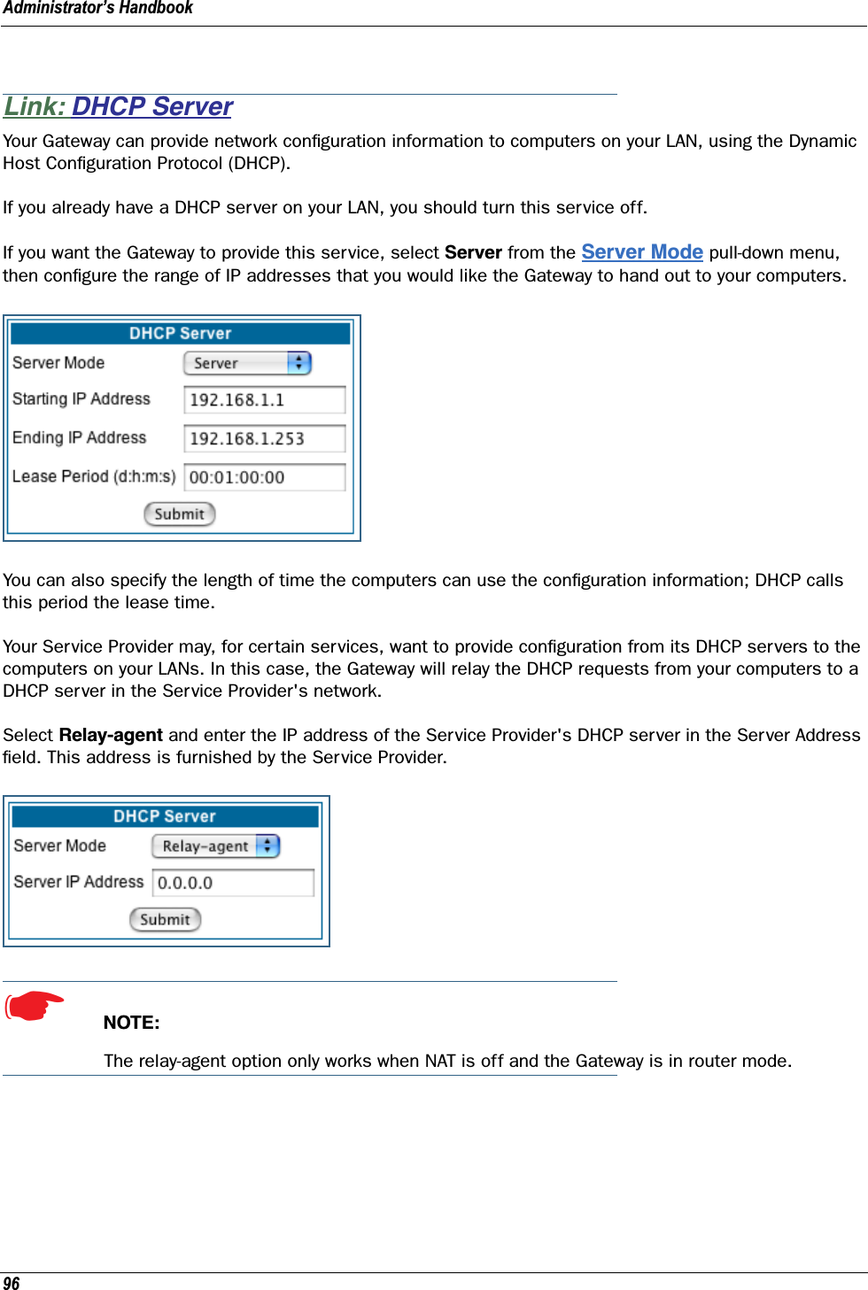
![249set dhcp range [ 2... 8 ] start-address ip_addressSpecifies the starting IP address of DHCP range n when subnet n option is on. See “Additional subnets” on page 262.set dhcp range [ 2... 8 ] end-address ip_addressSpecifies the ending IP address of DHCP range n when subnet n option is on. See “Additional subnets” on page 262.set dhcp reserved ip-address x.x.x.x mac-address y-y-y-y-y-yIf you selected server, reserves the specified IP address from the DHCP pool to the specified MAC address. These are list items; a total of 16 reserved addresses are supported. Secondary ranges will all make use of the dhcp lease-time value.DHCP Generic OptionsBeginning with Firmware Version 7.7.2, you can specify DHCP Generic Options which allow you to configure the content to be served for particular option numbers.set dhcp gen-option name nameSpecifies a DHCP generic option set named name of one to 15 characters. You can specify up to 20 gen-options. Each can contain up to 100 bytes of data, up to a maximum of 912 bytes of options data total. An option will be served only if the client requests it.set dhcp gen-option option [ 1 – 255 ]Specifies the DHCP option by number, 1 – 255. The following table shows the formats and sizes for known options, and whether or not you can configure a gen-option of that type. Option Data Format Data Size (bytes)Can Configure0 Empty 0 No1 IP mask 4 Yes2 Unsigned 4 byte integer 4 Yes3 - 11 IP address list Multiples of 4 Yes12 String (up to 100 characters) N Yes13 Unsigned 2 byte integer 2 Yes14 - 15 String (up to 100 characters) N Yes16 Unsigned 4 byte integer 4 Yes17 String (up to 100 characters) N Yes18 String (up to 100 characters) N Yes19 - 20 Flag 1 Yes21 IP address & mask list Multiples of 8 Yes22 Unsigned 2 byte integer 2 Yes](https://usermanual.wiki/ARRIS/224762/User-Guide-1097848-Page-249.png)
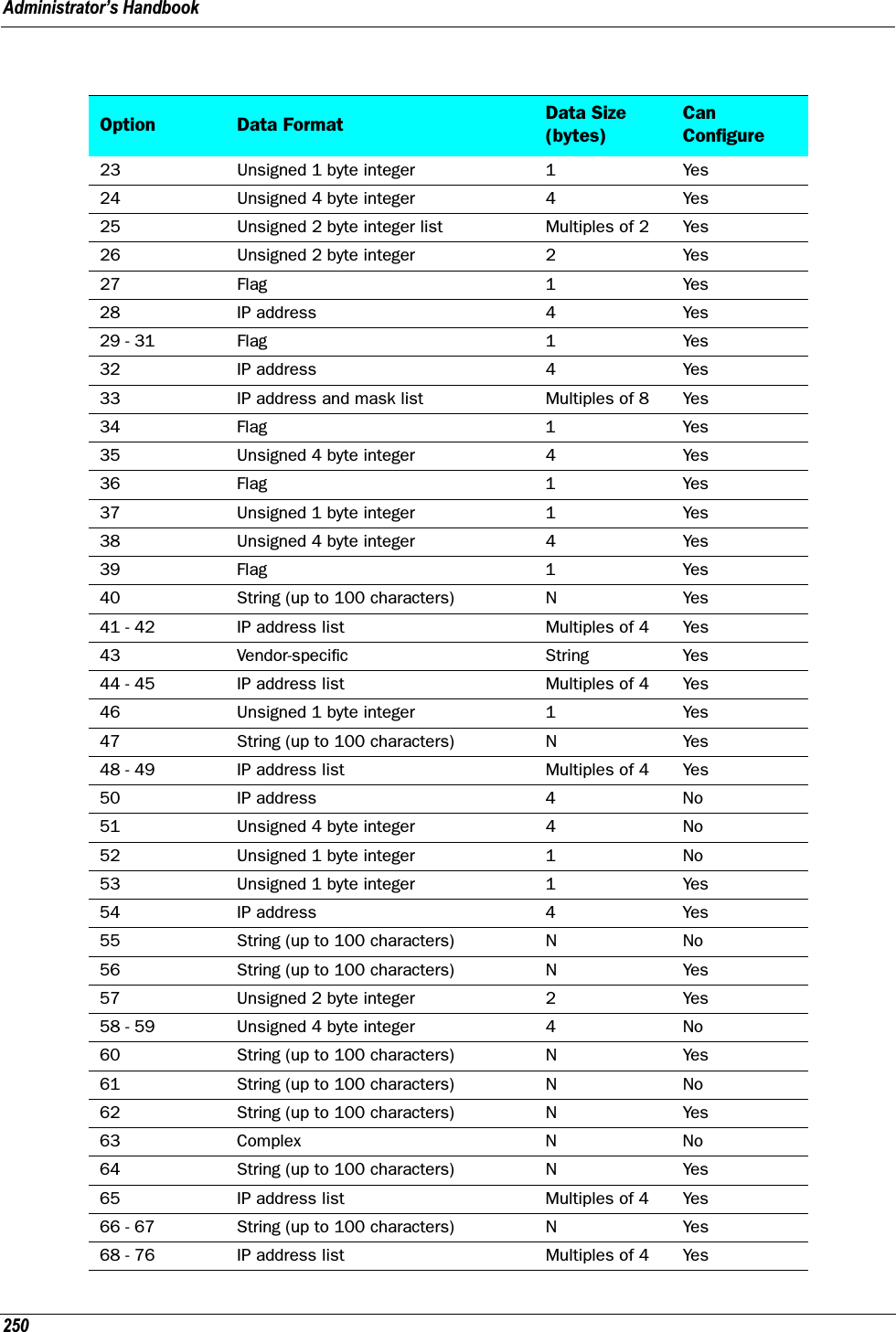
![251set dhcp gen-option data-type [ ascii | hex | dotted-decimal ]Specifies the DHCP gen-option data type: ascii, hex or dotted-decimal.set dhcp gen-option data dataSpecifies the gen-option data.•If the data-type is ascii, then any printable character + octal representations (e.g.”\0007”) and hex representations (e.g. “\xA4”).•If the data-type is hex, then an even number of hex characters (e.g. “0123456789AbcdEf”•If the data-type is dotted-decimal, then a series of numbers between 0 and 255, separated by a period (.). IP addresses are generally represented in this form.77 Pascal string list (length byte + data) N Yes78 - 79 Complex N No80 Empty 0 No81 Complex N No82 Sub-option list N Yes83 Complex N No84 Undefined ?? Yes85 IP address list Multiples of 4 Yes86 - 87 Unicode String Multiples of 2 Yes88 Encoded DN list N Yes89 IP address list Multiples of 4 Yes90 Complex N No91 - 97 Undefined/Weakly defined ?? Yes98 String (up to 100 characters) N Yes99 - 115 Undefined/Weakly defined ?? Yes116 Flag 1 Yes117 Unsigned 2 byte integer list Multiples of 2 Yes118 IP address 4 Yes119 Encoded DN list 2 N Yes120 Encoded DN list or IPAddress list N Yes121 - 125 Complex N No126 - 127 Undefined N Yes128 IP address list Multiples of 4 Yes129 - 223 Undefined/Weakly defined ?? Yes224 - 254 Private Use N Yes249 (note) Microsoft uses this instead of 121 N Yes255 Empty 0 NoOption Data Format Data Size (bytes)Can Configure](https://usermanual.wiki/ARRIS/224762/User-Guide-1097848-Page-251.png)
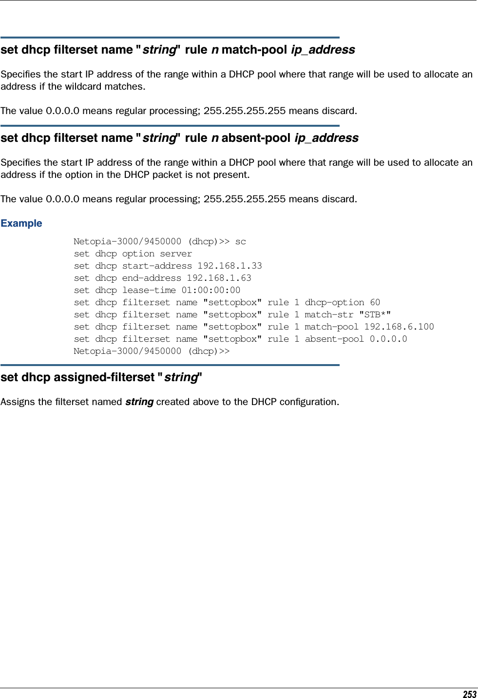
![Administrator’s Handbook252DHCP Option FilteringBeginning with Firmware Version 7.7, support for DHCP option filtering is provided via the filterset settings.set dhcp filterset name "string" rule n type [ dhcp-option | hw-address | requested-option ]Specifies a DHCP filterset named string as one of three possible types: The rule can either specify an option and option contents, dhcp-option; a client hardware address range, hw-address; or an option the client is requesting, requested-option. For hw-address, you will need to enter start-address and end-address values; for the others a dhcp-option parameter must be set.By default a rule is of type dhcp-option, for backwards compatibility.set dhcp filterset name "string" rule n dhcp-option [ 0... 255 ]Creates a DHCP filterset named string, for example “settopbox,” with rule number n.Up to two filtersets can be added. Your Gateway supports a single LAN DHCP server instance, but an addi-tional filterset is available for use when bridging, to block undesired DHCP traffic. Up to 8 rules can be cre-ated in the filterset, which are evaluated in order.dhcp-option determines which DHCP option should be compared. A typical value would be to use option 60 data for comparison, but allowing this value to be configured permits more flexibility.set dhcp filterset name "settopbox" rule 1 type dhcp-optionset dhcp filterset name "string" rule n match-action [ pass | discard | continue ]Assigns a match action to the filterset. If set to pass the match-pool address is shown. set dhcp filterset name "string" rule n absent-action [ pass | discard | continue ] Assigns an absent action to the filterset. If set to pass the absent-pool address is hidden.set dhcp filterset name "string" rule n match-option-group "option_group*"Assigns the option group named option_group to match.set dhcp filterset name "string" rule n match-str "match_string*"Assigns a match string to the filterset. The match-str string will be compared against the DHCP DISCOVER option data. This string can contain multiple “*” and “?” wildcard substitutions.](https://usermanual.wiki/ARRIS/224762/User-Guide-1097848-Page-252.png)
![Administrator’s Handbook254DMT SettingsDSL Commandsset dmt dsl-annex-support [ off | on ]This controls whether other annex support (just as Annex M) is enabled. Default is off.set dmt type [ lite | dmt | ansi | multi | adsl2 | adsl2+ | readsl2 | adsl2anxm | adsl2+anxm ] Selects the type of Discrete Multitone (DMT) asynchronous digital subscriber line (ADSL) protocol to use for the WAN interface.The type value also supports the following settings on certain model units: adsl2, adsl2+, readsl2, adsl2anxm, adsl2+anxm.☛ NOTE:Some dmt type settings are now supported for many Annex B (335xN) platforms. 2200 Series and 33xxN Series models are supported. Currently, adsl2anxm and adsl2+anxm are not sup-ported in Annex B.set dmt autoConfig [ off | on ]Enables support for automatic VPI/VCI detection and configuration. When set to on (the default), a pre-defined list of VPI/VCI pairs are searched to find a valid configuration for your ADSL line. Entering a value for the VPI or VCI setting will disable this feature.set dmt dmt dying-gasp [ default | off | on ]Enables or disables Gateway “dying gasp” behavior in cases of power failure. Default is off.set dmt wiringMode [ auto | tip_ring | A_A1 ](not supported on all models) This command configures the wiring mode setting for your ADSL line. Select-ing auto (the default) causes the Gateway to detect which pair of wires (inner or outer pair) are in use on your phone line. Specifying tip_ring forces the inner pair to be used; and A_A1 the outer pair.set dmt metallic-termination [ auto | disabled | always_on ](not supported on all models) This command allows you to apply a sealing current to “dry” DSL lines so that the wiring doesn’t corrode.•auto - The device will scan for standard telephone service (POTS). If it finds POTS, it disables metallic termination. If it does not find POTS during the search period, then metallic termination is enabled.•disabled - There is no POTS detection, and metallic termination is disabled.•always_on - The device will scan for POTS for information only. Metallic termination is always enabled.](https://usermanual.wiki/ARRIS/224762/User-Guide-1097848-Page-254.png)
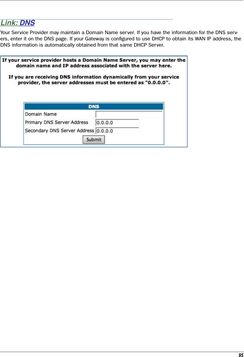
![255Domain Name System SettingsDomain Name System (DNS) is an information service for TCP/IP networks that uses a hierarchical naming system to identify network domains and the hosts associated with them. You can identify a primary DNS server and one secondary server.Common Commandsset dns domain-name domain-name Specifies the default domain name for your network. When an application needs to resolve a host name, it appends the default domain name to the host name and asks the DNS server if it has an address for the “fully qualified host name.” set dns primary-address ip_address Specifies the IP address of the primary DNS name server. set dns proxy-enableThis allows you to disable the default behavior of acting as a DNS proxy. The default is on.set dns secondary-address ip_addressSpecifies the IP address of the secondary DNS name server. Enter 0.0.0.0 if your network does not have a secondary DNS name server.set dns configured-dns-priority [ 0 - 255 ]Sets the configured DNS priority relative to acquired DNS. These server addresses may be acquired via DHCP (client), PPP, or statically configured. A “DNS learned-server-priority” is assigned to each configured interface. By default, configured DNSes have the highest priority (lowest number), then PPP-acquired DNSes, and DHCP-acquired DNSes have lowest priority (highest number).The default priorities for each type are:•Configured DNSes: 10•PPP-acquired: 20•DHCP-acquired: 30](https://usermanual.wiki/ARRIS/224762/User-Guide-1097848-Page-255.png)
![Administrator’s Handbook256Dynamic DNS SettingsDynamic DNS support allows you to use the free services of www.dyndns.org. Dynamic DNS automatically directs any public Internet request for your computer's name to your current dynamically-assigned IP address. This allows you to get to the IP address assigned to your Gateway, even though your actual IP address may change as a result of a PPPoE connection to the Internet.set dynamic-dns option [ off | dyndns.org ]set dynamic-dns ddns-host-name myhostname.dyndns.orgset dynamic-dns ddns-user-name myusernameset dynamic-dns ddns-user-password myuserpasswordEnables or disables dynamic DNS services. The default is off. If you specify dyndns.org, you must supply your hostname, username for the service, and password.Because different dynamic DNS vendors use different proprietary protocols, currently only www.dyndns.org is supported.](https://usermanual.wiki/ARRIS/224762/User-Guide-1097848-Page-256.png)
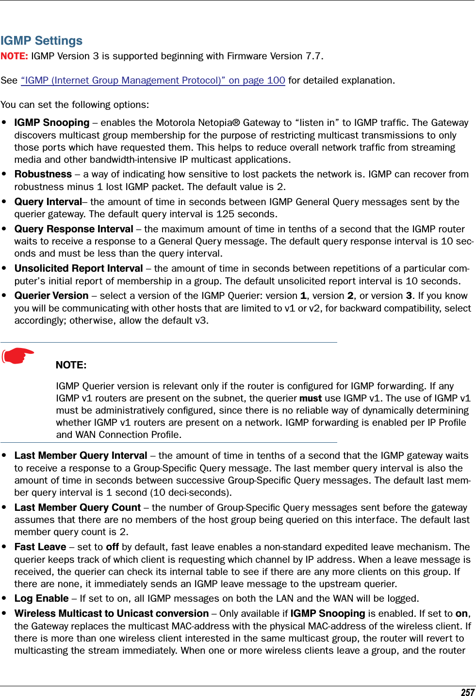
![Administrator’s Handbook258determines that only a single wireless client is interested in the stream, it will once again unicast the stream.set igmp snooping [ off | on ]Enables IGMP Snooping.set igmp robustness valueSets IGMP robustness range: from 2 – 255. The default is 2.set igmp query-intvl valueSets the query-interval range: from 10 seconds – 600 seconds, The default is 125 seconds.set igmp query-response-intvl valueSets the query-response interval range: from 5 deci-seconds (tenths of a second) – 255 deci-seconds. The default is 100 deci-seconds.set igmp unsol-report-intvl valueSets the unsolicited report interval: the amount of time in seconds between repetitions of a particular com-puter’s initial report of membership in a group. The default is 10 seconds.set igmp version [ 1 | 2 | 3 ]Sets the IGMP querier version: version 1, version 2, or version 3. If you know you will be communicating with other hosts that are limited to v1, for backward compatibility, select 1; otherwise, allow the default 3.set igmp last-member-query-intvl valueSets the last member query interval: the amount of time in tenths of a second that the IGMP gateway waits to receive a response to a Group-Specific Query message. The last member query interval is also the amount of time in seconds between successive Group-Specific Query messages. The default is 1 second (10 deci-seconds).set igmp last-member-query-count valueSets the last member query count: the number of Group-Specific Query messages sent before the gateway assumes that there are no members of the host group being queried on this interface. The default is 2.set igmp fast-leave [ off | on ]Sets fast leave on or off. Set to off by default, fast leave enables a non-standard expedited leave mecha-nism. The querier keeps track of which client is requesting which channel by IP address. When a leave mes-sage is received, the querier can check its internal table to see if there are any more clients on this group. If there are none, it immediately sends an IGMP leave message to the upstream querier.](https://usermanual.wiki/ARRIS/224762/User-Guide-1097848-Page-258.png)
![259set igmp wireless-m2u [ on | off ]This command allows you enable or disable wireless multicast-to-unicast if igmp snooping is set to on.set igmp log-enable [ on | off ]If set to on, all IGMP messages on both the LAN and the WAN will be logged. Default is off.IP SettingsYou can use the command line interface to specify whether TCP/IP is enabled, identify a default Gateway, and to enter TCP/IP settings for the Motorola Netopia® Gateway LAN and WAN ports.☛ NOTE:For the DSL platform you must identify the virtual PPP interface [vccn], a number from 1 to 8.Common Settingsset ip option { on | off }Enables or disables TCP/IP services in the Motorola Netopia® Gateway. You must enable TCP/IP services before you can enter other TCP/IP settings for the Motorola Netopia® Gateway. If you turn off TCP/IP ser-vices and save the new configuration, the Motorola Netopia® Gateway clears its TCP/IP settings. ARP Timeout Settingsset ip arp-timeout [ 60 ... 6000 ]Sets the timeout value for ARP timeout. Default = 600 secs (10 mins); range = 60 secs - 6000 secs (1–100 mins).DSL Settingsset ip dsl vccn address ip_addressAssigns an IP address to the virtual circuit. Enter 0.0.0.0 if you want the virtual circuit to obtain its IP address from a remote DHCP server.set ip dsl vccn broadcast broadcast_addressSpecifies the broadcast address for the TCP/IP network connected to the virtual circuit. IP hosts use the broadcast address to send messages to every host on your network simultaneously.The broadcast address for most networks is the network number followed by 255. For example, the broad-cast address for the 192.168.1.0 network would be 192.168.1.255.](https://usermanual.wiki/ARRIS/224762/User-Guide-1097848-Page-259.png)
![Administrator’s Handbook260set ip dsl vccn netmask netmaskSpecifies the subnet mask for the TCP/IP network connected to the virtual circuit. The subnet mask speci-fies which bits of the 32-bit binary IP address represents network information. The default subnet mask for most networks is 255.255.255.0 (Class C subnet mask).set ip dsl vccn restrictions { admin-disabled | none }Specifies restrictions on the types of traffic the Motorola Netopia® Gateway accepts over the DSL virtual circuit. The admin-disabled argument means that access to the device via telnet, web, and SNMP is disabled. RIP and ICMP traffic is still accepted. The none argument means that all traffic is accepted.set ip dsl vccn addr-mapping { on | off }Specifies whether you want the Motorola Netopia® Gateway to use network address translation (NAT) when communicating with remote routers. Address mapping lets you conceal details of your network from remote routers. It also permits all LAN devices to share a single IP address. By default, address mapping is turned “On”.set ip dsl vccn auto-sensing [ off | dhcp/pppoe | pppoe/pppoa ]Enables or disables DHCP/PPPoE or PPPoE/PPPoA autosensing on the specified interface. Setting this to DHCP/PPPoE enables automatic sensing of your WAN connection type: PPPoE or DHCP. The gateway attempts to connect using PPPoE first. If the Gateway fails to connect after 60 seconds, it switches to DHCP. As soon as it can connect via DHCP, the Gateway chooses and sets DHCP as its default. Otherwise, after attempting to connect via DHCP for 60 seconds, the Gateway switches back to PPPoE. The Gateway will continue to switch back and forth in this manner until it successfully connects. Similarly, selecting PPPoE/PPPoA causes the Gateway to attempt to connect by trying these protocols in parallel, and using the first one that is successful.set ip dsl vccn mcast-fwd [ on | off }Enables or disables multi-cast forwarding on the specified interface. If set to on, this interface acts as an IGMP proxy host, and IGMP packets are transmitted and received on this interface on behalf of IGMP hosts on the LAN interface.set ip dsl vccn igmp-null-source-addr { on | off }Specifies whether you want the Motorola Netopia® Gateway to identify the source IP address of every IGMP packet transmitted from this interface as 0.0.0.0 when mcast-fwd is set to on. This complies with the requirements of TR-101, and removes the need for a publicly advertised IP address on the WAN interface.set ip dsl vccn unnumbered [ on | off }Specifies whether you want the Motorola Netopia® Gateway to have its WAN interface unnumbered, i.e. set to 0. unnumbered option is only available if the address is set to 0 for the interface. Enables or disables unnumbered IP addressing (where an address of 0 is allowed AND the DHCP client is disabled) on the spec-ified interface. This setting applies to native IP as well as PPP inter faces to support running an IPoE inter-face without an address.](https://usermanual.wiki/ARRIS/224762/User-Guide-1097848-Page-260.png)
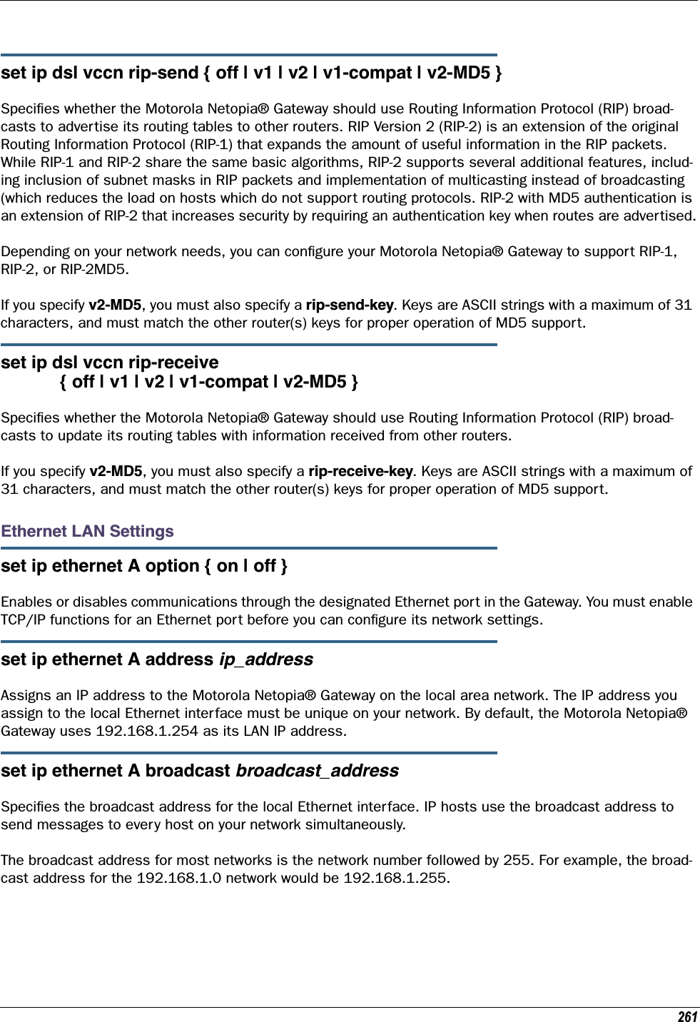
![Administrator’s Handbook262set ip ethernet A netmask netmaskSpecifies the subnet mask for the local Ethernet inter face. The subnet mask specifies which bits of the 32-bit binary IP address represent network information. The default subnet mask for most networks is 255.255.255.0 (Class C subnet mask).set ip ethernet A restrictions { none | admin-disabled }Specifies whether an administrator can open a telnet connection to a Motorola Netopia® Gateway over an Ethernet inter face (A = the LAN) to monitor and configure the unit.The admin-disabled argument prevents access to the device via telnet, web, and SNMP.By default, administrative restrictions are none on the LAN, but admin-disabled is set on the WAN. This means that, by default, an administrator can open, for example, a telnet connection from the LAN, but not the WAN.set ip ethernet A rip-send { off | v1 | v2 | v1-compat | v2-MD5 }Specifies whether the Motorola Netopia® Gateway should use Routing Information Protocol (RIP) broad-casts to advertise its routing tables to other routers on your network. RIP Version 2 (RIP-2) is an extension of the original Routing Information Protocol (RIP-1) that expands the amount of useful information in the RIP packets. While RIP-1 and RIP-2 share the same basic algorithms, RIP-2 supports several additional fea-tures, including inclusion of subnet masks in RIP packets and implementation of multicasting instead of broadcasting (which reduces the load on hosts which do not support routing protocols. RIP-2 with MD5 authentication is an extension of RIP-2 that increases security by requiring an authentication key when routes are advertised.If you specify v2-MD5, you must also specify a rip-send-key. Keys are ASCII strings with a maximum of 31 characters, and must match the other router(s) keys for proper operation of MD5 support.Depending on your network needs, you can configure your Motorola Netopia® Gateway to support RIP-1, RIP-2, or RIP-2MD5.set ip ethernet A rip-receive { off | v1 | v2 | v1-compat | v2-MD5 }Specifies whether the Motorola Netopia® Gateway should use Routing Information Protocol (RIP) broad-casts to update its routing tables with information received from other routers on your network.If you specify v2-MD5, you must also specify a rip-receive-key. Keys are ASCII strings with a maximum of 31 characters, and must match the other router(s) keys for proper operation of MD5 support.Additional subnetsSee “DHCP Settings” on page 248 for subnet range configuration commands.set ip ethernet A subnet [ 2 ... 8 ] option [ on | off ]Enables or disables additional LAN subnets. Up to seven additional subnets may be configured.](https://usermanual.wiki/ARRIS/224762/User-Guide-1097848-Page-262.png)
![263set ip ethernet A subnet n address ip_addressSpecifies an IP address for the subnet n, when subnet n option is on.set ip ethernet A subnet n netmask netmaskSpecifies the subnet mask for the subnet n, when subnet n option is on.Default IP Gateway Settingsset ip gateway option { on | off }Specifies whether the Motorola Netopia® Gateway should send packets to a default Gateway if it does not know how to reach the destination host.set ip gateway interface { ip-address | ppp-vccn }Specifies how the Motorola Netopia® Gateway should route information to the default Gateway. If you select ip-address, you must enter the IP address of a host on a local or remote network. If you specify ppp, the Motorola Netopia® unit uses the default gateway being used by the remote PPP peer.IP-over-PPP Settings. Use the following commands to configure settings for routing IP over a virtual PPP interface.☛ NOTE:For a DSL platform you must identify the virtual PPP interface [vccn], a number from 1 to 8. set ip ip-ppp [vccn] option { on | off }Enables or disables IP routing through the virtual PPP interface. By default, IP routing is turned on. If you turn off IP routing and save the new configuration, the Motorola Netopia® Gateway clears IP routing set-tingsset ip ip-ppp [vccn] address ip_addressAssigns an IP address to the virtual PPP interface. If you specify an IP address other than 0.0.0.0, your Motorola Netopia® Gateway will not negotiate its IP address with the remote peer. If the remote peer does not accept the IP address specified in the ip_address argument as valid, the link will not come up.The default value for the ip_address argument is 0.0.0.0, which indicates that the virtual PPP interface will use the IP address assigned to it by the remote peer. Note that the remote peer must be configured to supply an IP address to your Motorola Netopia® Gateway if you enter 0.0.0.0 for the ip_address argu-ment.](https://usermanual.wiki/ARRIS/224762/User-Guide-1097848-Page-263.png)
![Administrator’s Handbook264set ip ip-ppp [vccn] peer-address ip_addressSpecifies the IP address of the peer on the other end of the PPP link. If you specify an IP address other than 0.0.0.0, your Motorola Netopia® Gateway will not negotiate the remote peer's IP address. If the remote peer does not accept the address in the ip_address argument as its IP address (typically because it has been configured with another IP address), the link will not come up.The default value for the ip_address argument is 0.0.0.0, which indicates that the virtual PPP interface will accept the IP address returned by the remote peer. If you enter 0.0.0.0, the peer system must be con-figured to supply this address.set ip ip-ppp [vccn] restrictions { admin-disabled | none }Specifies restrictions on the types of traffic the Motorola Netopia® Gateway accepts over the PPP virtual circuit. The admin-disabled argument means that access to the device via telnet, web, and SNMP is disabled. RIP and ICMP traffic is still accepted. The none argument means that all traffic is accepted.set ip ip-ppp [vccn] addr-mapping [ on | off ]Specifies whether you want the Motorola Netopia® Gateway to use network address translation (NAT) when communicating with remote routers. Address mapping lets you conceal details of your network from remote routers. It also permits all LAN devices to share a single IP address. By default, address mapping is turned “On”.set ip ip-ppp [vccn] auto-sensing [ off | dhcp/pppoe | pppoe/pppoa ]Enables or disables DHCP/PPPoE or PPPoE/PPPoA autosensing on the specified interface. Setting this to DHCP/PPPoE enables automatic sensing of your WAN connection type: PPPoE or DHCP. The gateway attempts to connect using PPPoE first. If the Gateway fails to connect after 60 seconds, it switches to DHCP. As soon as it can connect via DHCP, the Gateway chooses and sets DHCP as its default. Otherwise, after attempting to connect via DHCP for 60 seconds, the Gateway switches back to PPPoE. The Gateway will continue to switch back and forth in this manner until it successfully connects. Similarly, selecting PPPoE/PPPoA causes the Gateway to attempt to connect by trying these protocols in parallel, and using the first one that is successful.set ip ip-ppp [vccn] rip-send { off | v1 | v2 | v1-compat | v2-MD5 }Specifies whether the Motorola Netopia® Gateway unit should use Routing Information Protocol (RIP) broad-casts to advertise its routing tables to routers on the other side of the PPP link. An extension of the original Routing Information Protocol (RIP-1), RIP Version 2 (RIP-2) expands the amount of useful information in the packets. While RIP-1 and RIP-2 share the same basic algorithms, RIP-2 supports several new features. For example, inclusion of subnet masks in RIP packets and implementation of multicasting instead of broad-casting. This last feature reduces the load on hosts which do not support routing protocols. RIP-2 with MD5 authentication is an extension of RIP-2 that increases security by requiring an authentication key when routes are advertised.This command is only available when address mapping for the specified virtual circuit is turned “off”.If you specify v2-MD5, you must also specify a rip-send-key. Keys are ASCII strings with a maximum of 31 characters, and must match the other router(s) keys for proper operation of MD5 support.](https://usermanual.wiki/ARRIS/224762/User-Guide-1097848-Page-264.png)
![265set ip ip-ppp [vccn] rip-receive { off | v1 | v2 | v1-compat | v2-MD5 }Specifies whether the Motorola Netopia® Gateway should use Routing Information Protocol (RIP) broad-casts to update its routing tables with information received from other routers on the other side of the PPP link.If you specify v2-MD5, you must also specify a rip-receive-key. Keys are ASCII strings with a maximum of 31 characters, and must match the other router(s) keys for proper operation of MD5 support.set ip ip-ppp vccn igmp-null-source-addr [ on | off ]Specifies whether you want the Motorola Netopia® Gateway to identify the source IP address of every IGMP packet transmitted from this interface as 0.0.0.0 when mcast-fwd is set to on. This complies with the requirements of TR-101, and removes the need for a publicly advertised IP address on the WAN interface.set ip ip-ppp vccn mcast-fwd [ on | off ]Specifies whether you want the Motorola Netopia® Gateway interface to act as an IGMP proxy host.set ip ip-ppp vccn unnumbered [ on | off ]Specifies whether you want the Motorola Netopia® Gateway to have its WAN interface unnumbered, i.e. set to 0. set ip ip-ppp vccn dns acquired-dns-priority [ 0 - 255 ]Sets the priority for DNS acquired via PPP. See “Domain Name System Settings” on page 255 for more information.](https://usermanual.wiki/ARRIS/224762/User-Guide-1097848-Page-265.png)
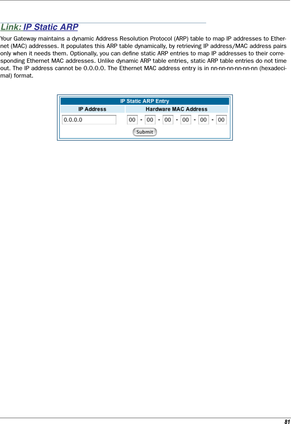
![Administrator’s Handbook266Static ARP SettingsYour Motorola Netopia® Gateway maintains a dynamic Address Resolution Protocol (ARP) table to map IP addresses to Ethernet (MAC) addresses. Your Motorola Netopia® Gateway populates this ARP table dynam-ically, by retrieving IP address/MAC address pairs only when it needs them. Optionally, you can define static ARP entries to map IP addresses to their corresponding Ethernet MAC addresses. Unlike dynamic ARP table entries, static ARP table entries do not time out.You can configure as many as 16 static ARP table entries for a Motorola Netopia® Gateway. Use the follow-ing commands to add static ARP entries to the Motorola Netopia® Gateway static ARP table:set ip static-arp ip-address ip_addressSpecifies the IP address for the static ARP entry. Enter an IP address in the ip_address argument in dot-ted decimal format. The ip_address argument cannot be 0.0.0.0.set ip static-arp ip-address ip_address hardware-address MAC_addressSpecifies the Ethernet hardware address for the static ARP entry. Enter an Ethernet hardware address in the MAC_address argument in nn.nn.nn.nn.nn.nn (hexadecimal) format.IGMP Forwardingset ip igmp-forwarding [ off | on ]Turns IP IGMP forwarding off or on. The default is off.IPsec Passthroughset ip ipsec-passthrough [ off | on ]Turns IPsec client passthrough off or on. The default is on.IP Prioritizationset ip prioritize [ off | on ]Allows you to support traffic that has the TOS bit set. This defaults to off.](https://usermanual.wiki/ARRIS/224762/User-Guide-1097848-Page-266.png)
![267Differentiated Services (DiffServ)set diffserv option [ off | on ]Turns the DiffServ option off (default) or on. on enables the service and IP TOS bits are used, even if no flows are defined. Consequently, if the end-point nodes provide TOS settings from an application that can be interpreted as one of the supported states, the Gateway will handle it as if it actively marked the TOS field itself.☛ NOTE:The Gateway itself will not override TOS bit settings made by the endpoints. Support for source-provided IP TOS priorities within the Gateway is achieved simply by turning the Diff-Serve option “on” and by setting the lohi-asymmetry to adjust the behavior of the Gateway’s internal queues.set diffserv lohi-ratio [ 60 - 100 percent ]Sets a percentage between 60 and 100 used to regulate the level of packets allowed to be pending in the low priority queue. The default is 92. It can be used in some degree to adjust the relative throughput band-width for low- versus high-priority traffic.☛ NOTE:diffserv lohi-ratio has been removed for VDSL, ADSL bonded units.](https://usermanual.wiki/ARRIS/224762/User-Guide-1097848-Page-267.png)
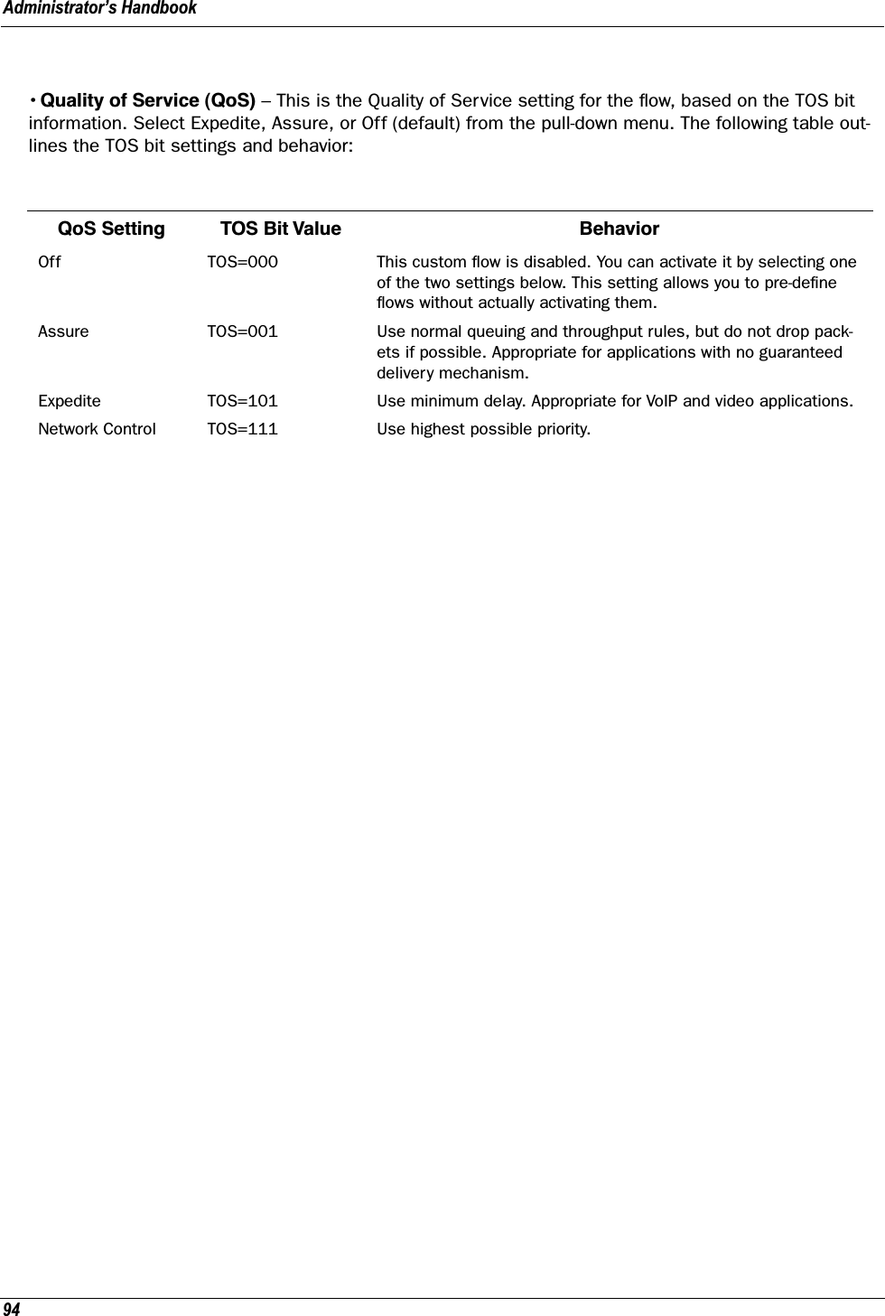
![Administrator’s Handbook268set diffserv custom-flows name name protocol [ TCP | UDP | ICMP | other ] direction [ outbound | inbound | both ] start-port [ 0 - 65535 ] end-port [ 0 - 65535 ] inside-ip inside-ip-addr inside-ip-mask inside-ip-netmask outside-ip outside-ip-addr outside-ip-mask outside-ip-netmask qos [ off | assure | expedite | network-control ]Defines or edits a custom flow. Select a name for the custom-flow from the set command. The CLI will step into the newly-named or previously-defined flow for editing.•protocol – Allows you to choose the IP protocol for the stream: TCP, UDP, ICMP, or other.other is appropriate for setting up flows on protocols with non-standard port definitions, for example, IPSEC or PPTP. If you select other, an additional field, numbered-protocol will appear with a range of 0–255. Choose the protocol number from this field.•direction – Allows you to choose whether to apply the marking and gateway queue behavior for inbound packets, outbound packets, or to both. If the Gateway is used as an “edge” gateway, its more important function is to mark the packets for high-priority streams in the outbound direction.•start-port/end-port – Allows you to specify a range of ports to check for a particular flow, if the protocol selection is TCP or UDP.•inside-ip/mask – If you want packets originating from a certain LAN IP address to be marked, enter the IP address and subnet mask here. If you leave the address equal to zero, this check is ignored for out-bound packets. The check is always ignored for inbound packets. The DiffServe queuing function must be applied ahead of NAT; and, before NAT re-maps the inbound packets, all inbound packets are des-tined for the Gateway's WAN IP address.•outside-ip/mask – If you want packets destined for and originating from a certain WAN IP address to be marked, enter this address and subnet mask here. If you leave the address equal to zero, the outside address check is ignored. For outbound flows, the outside address is the destination IP address for the packets. For inbound packets, the outside address is the source IP address for the packets.Note: When setting the Inside/Outside IP Address/Netmask settings, note that a netmask value can be used to configure for a network rather than a single IP address.•qos – Allows you to specify the Quality of Service for the flow: off, assure, expedite or network-con-trol. These are used both to mark the IP TOS byte and to distribute packets into the queues as if they were marked by the source. QoS Setting TOS Bit Value BehaviorOff TOS=000 This custom flow is disabled. You can activate it by selecting one of the two settings below. This setting allows you to pre-define flows without actually activating them.Assure TOS=001 Use normal queuing and throughput rules, but do not drop pack-ets if possible. Appropriate for applications with no guaranteed delivery mechanism.Expedite TOS=101 Use minimum delay. Appropriate for VoIP and video applications.Network Control TOS=111 Use highest possible priority.](https://usermanual.wiki/ARRIS/224762/User-Guide-1097848-Page-268.png)
![269Packet Mapping Configurationset diffserv qos [ network-control-queue | expedite-queue | assured-queue | best-effort-queue ] queue_nameSpecifies the Diffserv QoS queue mapping associations.•queue_name - the basic queue name to which classified packets are directed.By default the following mappings are created:set diffserv qos network-control-queue basic_q0set diffserv qos expedite-queue basic_q1set diffserv qos assured-queue basic_q2set diffserv qos best-effort-queue basic_q3set diffserv qos dscp-map [ default | custom ]•default – the default DSCP-queue mappings are used•custom – allows you to set up customized mappings between DSCP code points and queue types.If custom is selected, the following can be configured:set diffserv qos dscp-map-0 [ best-effort | assured | expedite | network-control ]set diffserv qos dscp-map-1 [ best-effort | assured | expedite | network-control ]...set diffserv qos dscp-map-31 [ best-effort | assured | expedite | network-control ]By default, the following settings are used in custom mode:set diffserv qos dscp-map-0 best-effortset diffserv qos dscp-map-1 best-effortset diffserv qos dscp-map-2 best-effortset diffserv qos dscp-map-3 best-effortset diffserv qos dscp-map-4 best-effortset diffserv qos dscp-map-5 assuredset diffserv qos dscp-map-6 best-effortset diffserv qos dscp-map-7 best-effortset diffserv qos dscp-map-8 best-effortset diffserv qos dscp-map-9 assuredset diffserv qos dscp-map-10 best-effortset diffserv qos dscp-map-11 best-effortset diffserv qos dscp-map-12 best-effortset diffserv qos dscp-map-13 assuredset diffserv qos dscp-map-14 best-effortset diffserv qos dscp-map-15 best-effortset diffserv qos dscp-map-16 best-effortset diffserv qos dscp-map-17 assuredset diffserv qos dscp-map-18 best-effortset diffserv qos dscp-map-19 best-effort](https://usermanual.wiki/ARRIS/224762/User-Guide-1097848-Page-269.png)

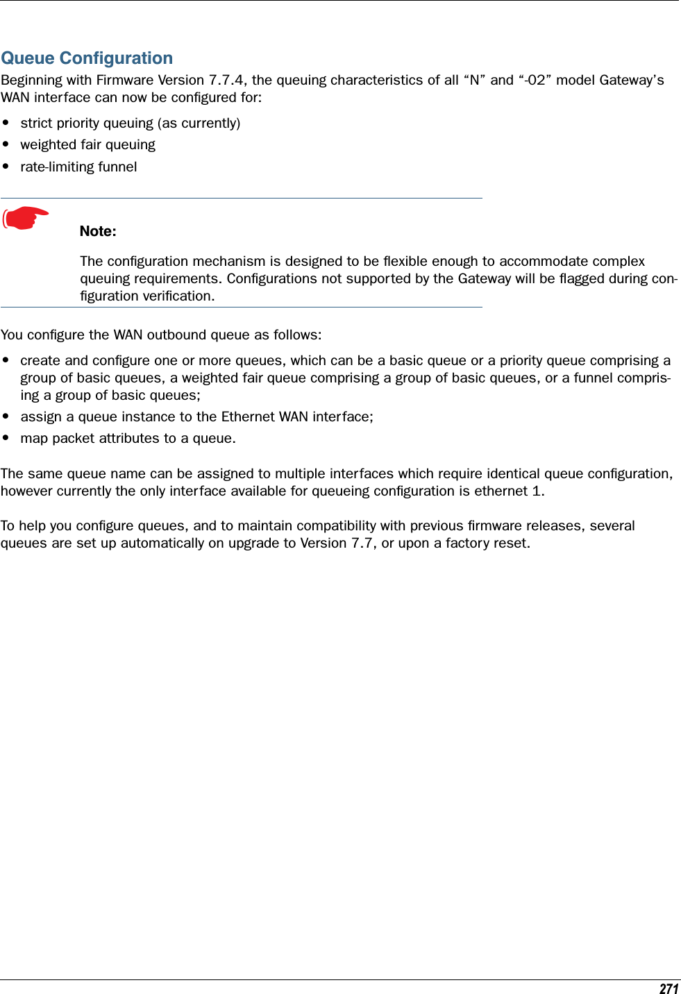
![Administrator’s Handbook272set queue name queue_name option [ on | off ] type [ basic | wfq | priority | funnel ]Creates a queue named queue_name and assigns a type:•basic – Basic Queue•wfq – Weighted Fair Queue•priority – Priority Queue•funnel – Funnel QueueBasic Queueset queue name basic_queue_name option [ on | off ]set queue name basic_queue_name type basicSpecifies the Basic Queue named basic_queue_name attributes. Basic queues have one input and one output. The basic queue is assigned an ID, with the following attribute: when the queue is full, discard.By default, the following Basic Queues are created:•basic_q0•basic_q1•basic_q2•basic_q3](https://usermanual.wiki/ARRIS/224762/User-Guide-1097848-Page-272.png)
![273Weighted Fair Queueset queue name wfq option [ on | off ]set queue name wf_queue_name type wfqset queue name wf_queue_name weight-type [ relative | bps ]set queue name wf_queue_name entry n input input_queue_nameset queue name wf_queue_name entry n weight weightset queue name wf_queue_name entry n share-bw [ on | off ]set queue name wf_queue_name entry n default-input queue_nameSpecifies the attributes of the Weighted Fair Queue named wf_queue_name.•wf_queue_name – name of weighted fair queueA weighted fair queue can contain up to 8 input queues. For each input queue, the following is configured:•weight-type – the weighted fair queue configuration allows you to set the rate in bits per second (bps) or percentage of the line rate (relative). bps is the default.•n – entry number for this input queue•input_queue_name – name of input queue•weight_value – numeric relative weight of queue•share-bw – if enabled, the bandwidth for this queue can be shared between other queues when idle.•default-input – specifies the default input queue name.The default special queuing configuration shapes the rate of a custom flow toward the Remote Manage-ment Server.By default, the following WFQ is created:set queue name "wfq" option onset queue name "wfq" type wfqset queue name "wfq" weight-type bpsset queue name "wfq" entry 1 input "basic_q0"set queue name "wfq" entry 1 weight 10000set queue name "wfq" entry 1 share-bw offset queue name "wfq" entry 2 input "basic_q1"set queue name "wfq" entry 2 weight 20000set queue name "wfq" entry 2 share-bw offset queue name "wfq" entry 3 input "basic_q2"set queue name "wfq" entry 3 weight 30000set queue name "wfq" entry 3 share-bw offset queue name "wfq" entry 4 input "basic_q3"set queue name "wfq" entry 4 weight 40000set queue name "wfq" entry 4 share-bw offset queue name "wfq" default-input "basic_q0"](https://usermanual.wiki/ARRIS/224762/User-Guide-1097848-Page-273.png)
![Administrator’s Handbook274Priority Queueset queue name priority_queue_name option [ off | on ]set queue name priority_queue_name type priorityset queue name priority_queue_name default-input queue_nameA priority queue can contain up to 8 input queues. For each input queue, the following is configured:set queue name priority_queue_name entry n input input_queue_name set queue name priority_queue_name entry n priority priority_valueSpecifies the Priority Queue named priority_queue_name attributes.•priority_queue_name – name of priority queue•input_queue_name – name of input queue•priority_value – numeric relative priority of queue. The higher the number, the higher the priority of the queue.•default-input – specifies the default input queue name.By default, the following priority queue is created:set queue name "pq" option onset queue name "pq" type priorityset queue name "pq" entry 1 input "basic_q0"set queue name "pq" entry 1 priority 10set queue name "pq" entry 2 input "basic_q1"set queue name "pq" entry 2 priority 20set queue name "pq" entry 3 input "basic_q2"set queue name "pq" entry 3 priority 30set queue name "pq" entry 4 input "basic_q3"set queue name "pq" entry 4 priority 40set queue name "pq" default-input "basic_q0"](https://usermanual.wiki/ARRIS/224762/User-Guide-1097848-Page-274.png)
![275Funnel QueueA funnel queue is used to limit the rate of the transmission below the actual line rate:set queue name funnel_queue_name option [ on | off ]set queue name funnel_queue_name type funnelset queue name funnel_queue_name input input_queue_name set queue name funnel_queue_name bps bpsSpecifies the Funnel Queue named funnel_queue_name attributes.•funnel_queue_name – name of funnel queue•input_queue_name – name of input queue•bps – max bits per second permitted through funnel queueBy default, the following funnel queues are created:Rate-limiting priority queue to 100Kbps:set queue name pq-100kbps option onset queue name pq-100kbps type funnelset queue name pq-100kbps input pqset queue name pq-100kbps bps 100000Rate-limiting weighted fair queue to 100Kbps:set queue name wfq-100kbps option onset queue name wfq-100kbps type funnelset queue name wfq-100kbps input wfqset queue name wfq-100kbps bps 100000Interface Queue AssignmentThe WAN ethernet queue is assigned as follows:set [ ethernet ethernet | ip ethernet B | ip-ppp vccn ] tx-queue queue_nameBy default, the WAN ethernet interface is assigned the default priority queue:set ethernet ethernet B tx-queue pqOther interfaces may likewise be assigned tx-queue values.](https://usermanual.wiki/ARRIS/224762/User-Guide-1097848-Page-275.png)
![Administrator’s Handbook276SIP Passthroughset ip sip-passthrough [ on | off ]Turns Session Initiation Protocol application layer gateway client passthrough on or off. The default is on.Session Initiation Protocol, is a signaling protocol for Internet conferencing, telephony, presence, events notification and instant messaging.RTSP Passthroughset ip ethernet B rtsp-passthrough [ off | on ]Turns Real Time Streaming Protocol application layer gateway client passthrough on or off. RTSP is a proto-col used for streaming media. It allows a client remotely to control a streaming media server. A typical application is Video-on-Demand (VoD). The default is on.Static Route SettingsA static route identifies a manually configured pathway to a remote network. Unlike dynamic routes, which are acquired and confirmed periodically from other routers, static routes do not time out. Consequently, static routes are useful when working with PPP, since an intermittent PPP link may make maintenance of dynamic routes problematic.You can configure as many as 32 static IP routes for a Motorola Netopia® Gateway. Use the following com-mands to maintain static routes to the Motorola Netopia® Gateway routing table:set ip static-routes destination-network net_addressSpecifies the network address for the static route. Enter a network address in the net_address argu-ment in dotted decimal format. The net_address argument cannot be 0.0.0.0.set ip static-routes destination-network net_address netmask netmaskSpecifies the subnet mask for the IP network at the other end of the static route. Enter the netmask argu-ment in dotted decimal format. The subnet mask associated with the destination network must represent the same network class (A, B, or C) or a lower class (such as a class C subnet mask for class B network number) to be valid.](https://usermanual.wiki/ARRIS/224762/User-Guide-1097848-Page-276.png)
![277set ip static-routes destination-network net_address interface { ip-address | ppp-vccn }Specifies the interface through which the static route is accessible.set ip static-routes destination-network net_address gateway-address gate_addressSpecifies the IP address of the Gateway for the static route. The default Gateway must be located on a net-work connected to the Motorola Netopia® Gateway configured interface.set ip static-routes destination-network net_address metric integerSpecifies the metric (hop count) for the static route. The default metric is 1. Enter a number from 1 to 15 for the integer argument to indicate the number of routers (actual or best guess) a packet must traverse to reach the remote network.You can enter a metric of 1 to indicate either:•The remote network is one router away and the static route is the best way to reach it;•The remote network is more than one router away but the static route should not be replaced by a dynamic route, even if the dynamic route is more efficient. set ip static-routes destination-network net_address rip-advertise [ splitHorizon | always | never ]Specifies whether the gateway should use Routing Information Protocol (RIP) broadcasts to advertise to other routers on your network and which mode to use. The default is splitHorizon.delete ip static-routes destination-network net_addressDeletes a static route. Deleting a static route removes all information associated with that route.IPMaps Settingsset ip-maps name <name> internal-ip <ip address>Specifies the name and static ip address of the LAN device to be mapped.set ip-maps name <name> external-ip <ip address>Specifies the name and static ip address of the WAN device to be mapped.Up to 8 mapped static IP addresses are supported.](https://usermanual.wiki/ARRIS/224762/User-Guide-1097848-Page-277.png)
![Administrator’s Handbook278Network Address Translation (NAT) Default SettingsNAT default settings let you specify whether you want your Motorola Netopia® Gateway to forward NAT traf-fic to a default server when it doesn’t know what else to do with it. The NAT default host function is useful in situations where you cannot create a specific NAT pinhole for a traffic stream because you cannot antici-pate what port number an application might use. For example, some network games select arbitrary port numbers when a connection is being opened. By identifying your computer (or another host on your network) as a NAT default server, you can specify that NAT traffic that would otherwise be discarded by the Motorola Netopia® Gateway should be directed to a specific hosts.set nat-default mode [ off | default-server | ip-passthrough ]Specifies whether you want your Motorola Netopia® Gateway to forward unsolicited traffic from the WAN to a default server or an IP passthrough host when it doesn’t know what else to do with it. See “Default Server” on page 89 for more information.set nat-default dhcp-enable [ on | off ]Allows the IP passthrough host to acquire its IP address via DHCP, if ip-passthrough is enabled. set nat-default address ip_addressSpecifies the IP address of the NAT default server.set nat-default host-hardware-address MAC_address }Specifies the hardware (MAC) address of the IP passthrough host. If the MAC address is specified as all-zeroes, the first DHCP client that requests an IP address gets the passthrough address.Network Address Translation (NAT) Pinhole SettingsNAT pinholes let you pass specific types of network traffic through the NAT interfaces on the Motorola Neto-pia® Gateway. NAT pinholes allow you to route selected types of network traffic, such as FTP requests or HTTP (Web) connections, to a specific host behind the Motorola Netopia® Gateway transparently.To set up NAT pinholes, you identify the type(s) of traffic you want to redirect by port number, and you spec-ify the internal host to which each specified type of traffic should be directed.The following list identifies protocol type and port number for common TCP/IP protocols:•FTP (TCP 21)•telnet (TCP 23)•SMTP (TCP 25),•TFTP (UDP 69)•SNMP (TCP 161, UDP 161) set pinhole name nameSpecifies the identifier for the entry in the router's pinhole table. You can name pinhole table entries sequentially (1, 2, 3), by port number (21, 80, 23), by protocol, or by some other naming scheme.](https://usermanual.wiki/ARRIS/224762/User-Guide-1097848-Page-278.png)
![279set pinhole name name protocol-select { tcp | udp }Specifies the type of protocol being redirected.set pinhole name name external-port-start [ 0 - 49151 ]Specifies the first port number in the range being translated.set pinhole name name external-port-end [ 0 - 49151 ]Specifies the last port number in the range being translated.set pinhole name name internal-ip internal-ipSpecifies the IP address of the internal host to which traffic of the specified type should be transferred.set pinhole name name internal-port [ 0 - 65535 ]Specifies the port number your Motorola Netopia® Gateway should use when forwarding traffic of the spec-ified type. Under most circumstances, you would use the same number for the external and internal port.PPPoE /PPPoA SettingsYou can use the following commands to configure basic settings, port authentication settings, and peer authentication settings for PPP interfaces on your Motorola Netopia® Gateway.Configuring Basic PPP Settings. ☛ NOTE:For the DSL platform you must identify the virtual PPP interface [vccn], a number from 1 to 8.set ppp module [vccn] option { on | off }Enables or disables PPP on the Motorola Netopia® Gateway.set ppp module [vccn] auto-connect { on | off }Supports manual mode required for some vendors. The default on is not normally changed. If auto-connect is disabled (off), you must manually start/stop a ppp connection.set ppp module [vccn] mru integerSpecifies the Maximum Receive Unit (MRU) for the PPP interface. The integer argument can be any num-ber between 128 and 1492 for PPPoE; 1500 otherwise.](https://usermanual.wiki/ARRIS/224762/User-Guide-1097848-Page-279.png)
![Administrator’s Handbook280set ppp module [vccn] magic-number { on | off }Enables or disables LCP magic number negotiation.set ppp module [vccn] protocol-compression { on | off }Specifies whether you want the Motorola Netopia® Gateway to compress the PPP Protocol field when it transmits datagrams over the PPP link.set ppp module [vccn] lcp-echo-requests { on | off }Specifies whether you want your Motorola Netopia® Gateway to send LCP echo requests. You should turn off LCP echoing if you do not want the Motorola Netopia® Gateway to drop a PPP link to a nonresponsive peer.set ppp module [vccn] echo-period integerSpecifies the number of seconds the Motorola Netopia® Gateway should wait before sending another echo from an LCP echo request. The integer argument can be any number from between 5 and 300 (seconds).set ppp module [vccn] lost-echoes-max integerSpecifies the maximum number of lost echoes the Motorola Netopia® Gateway should tolerate before bringing down the PPP connection. The integer argument can be any number from between 1 and 20.set ppp module [vccn] failures-max integerSpecifies the maximum number of Configure-NAK messages the PPP module can send without having sent a Configure-ACK message. The integer argument can be any number between 1 and 20.set ppp module [vccn] configure-max integerSpecifies the maximum number of unacknowledged configuration requests that your Motorola Netopia® Gateway will send. The integer argument can be any number between 1 and 20.set ppp module [vccn] terminate-max integerSpecifies the maximum number of unacknowledged termination requests that your Motorola Netopia® Gateway will send before terminating the PPP link. The integer argument can be any number between 1 and 10. set ppp module [vccn] restart-timer integerSpecifies the number of seconds the Motorola Netopia® Gateway should wait before retransmitting a con-figuration or termination request. The integer argument can be any number between 1 and 30.](https://usermanual.wiki/ARRIS/224762/User-Guide-1097848-Page-280.png)
![281set ppp module [vccn] connection-type { instant-on | always-on }Specifies whether a PPP connection is maintained by the Motorola Netopia® Gateway when it is unused for extended periods. If you specify always-on, the Motorola Netopia® Gateway never shuts down the PPP link. If you specify instant-on, the Motorola Netopia® Gateway shuts down the PPP link after the number of seconds specified in the time-out setting (below) if no traffic is moving over the circuit.set ppp module [vccn] time-out integerIf you specified a connection type of instant-on, specifies the number of seconds, in the range 30 - 3600, with a default value of 300, the Motorola Netopia® Gateway should wait for communication activity before terminating the PPP link.Configuring Port Authentication. You can use the following command to specify how your Motorola Neto-pia® Gateway should respond when it receives an authentication request from a remote peer.The settings for port authentication on the local Motorola Netopia® Gateway must match the authentica-tion that is expected by the remote peer. For example, if the remote peer requires CHAP authentication and has a name and CHAP secret for the Motorola Netopia® Gateway, you must enable CHAP and specify the same name and secret on the Motorola Netopia® Gateway before the link can be established.set ppp module [vccn] port-authentication option [ off | on | pap-only | chap-only ]Specifying on turns both PAP and CHAP on, or you can select PAP or CHAP. Specify the username and password when port authentication is turned on (both CHAP and PAP, CHAP or PAP.) Authentication must be enabled before you can enter other information.set ppp module [vccn] port-authentication username usernameThe username argument is 1 – 255 alphanumeric characters. The information you enter must match the username configured in the PPP peer's authentication database. set ppp module [vccn] port-authentication password passwordThe password argument is 1 – 128 alphanumeric characters. The information you enter must match the password used by the PPP peer.](https://usermanual.wiki/ARRIS/224762/User-Guide-1097848-Page-281.png)
![Administrator’s Handbook282PPPoE with IPoE SettingsEthernet WAN platformsset wan-over-ether pppoe [ on | off ]Enables or disables PPPoE on the Ethernet WAN interface.set wan-over-ether pppoe-with-ipoe [ on | off ]Enables or disables the PPPoE with IPoE support on Ethernet WAN, including VDSL, platforms when pppoe option is set to on.When pppoe-with-ipoe is set to on, an additional interface, “ethernet C,” becomes available.set wan-over-ether ipoe-sessions [ 1 - 4 ]Sets the number of IPoE sessions, up to four, on Ethernet WAN, including VDSL, platforms.☛ NOTE: Enabling pppoe-with-ipoe disables support for multiple PPPoE sessions.Example:set ip ethernet C option onset ip ethernet C address 0.0.0.0set ip ethernet C broadcast 0.0.0.255set ip ethernet C netmask 255.255.255.0set ip ethernet C restrictions admin-disabledset ip ethernet C addr-mapping onset ip ethernet C dns acquired-dns-priority 20set ip ethernet C mcast-fwd onset ip ethernet C igmp-null-source-addr offset ip ethernet C tx-queue "none"set ip ethernet C unnumbered offset ip ethernet C rip-receive offset ip ethernet C proxy-arp offset ip ip-ppp enet-B option onset ip ip-ppp enet-B address 0.0.0.0set ip ip-ppp enet-B peer-address 0.0.0.0set ip ip-ppp enet-B restrictions admin-disabledset ip ip-ppp enet-B addr-mapping onset ip ip-ppp enet-B dns acquired-dns-priority 20set ip ip-ppp enet-B igmp-null-source-addr offset ip ip-ppp enet-B tx-queue "none"set ip ip-ppp enet-B mcast-fwd onset ip ip-ppp enet-B unnumbered offset ip ip-ppp enet-B rip-receive off](https://usermanual.wiki/ARRIS/224762/User-Guide-1097848-Page-282.png)
![283ADSL platformsYou must configure two VCCs with the same VPI/VCI to enable concurrent PPPoE and IPoE support, and you will need to configure the individual settings for each interface for proper operation.set atm vcc n encap pppoe-llcSpecifies that the VCC will allow a second VCC with the same VPI/VCI values as the first. pppoe-llc denotes this special case.Example:set atm option onset atm vcc 1 option onset atm vcc 1 vpi 0set atm vcc 1 vci 35set atm vcc 1 encap pppoe-llcset atm vcc 2 option onset atm vcc 2 vpi 0set atm vcc 2 vci 35set atm vcc 2 encap ether-llcThis will allow you to configure the second WAN interface.set atm vcc 2 vpi 0set atm vcc 2 vci 35set atm vcc 2 encap ether-llc...set ip ip-ppp vcc1 mcast-fwd [ on | off }Enables or disables multi-cast forwarding on the specified interface. If set to on, this interface acts as an IGMP proxy host, and IGMP packets are transmitted and received on this interface on behalf of IGMP hosts on the LAN interface. See “IGMP (Internet Group Management Protocol)” on page 100 for more informa-tion.set ip ip-ppp vcc1 igmp-null-source-addr [ off | on ]Enables or disables IGMP null source address, if mcast-fwd is set to on. If enabled, the source IP address of every IGMP packet transmitted from this interface is set to 0.0.0.0. This complies with the requirements of TR-101, and removes the need for a publicly advertised IP address on the WAN interface.Ethernet Port Settingsset ethernet ethernet A mode { auto | 100M-full | 100M-full-fixed | 100M-half-fixed | 10M-full-fixed | 10M-half-fixed | 100M-half | 10M-full | 10M-half }Allows mode setting for the ethernet port. Only supported on units without a LAN switch, or dual ethernet products (338x). In the dual ethernet case, “ethernet B” would be specified for the WAN port. The default is auto.](https://usermanual.wiki/ARRIS/224762/User-Guide-1097848-Page-283.png)
![Administrator’s Handbook284802.3ah Ethernet OAM Settings802.3ah Ethernet in the First Mile (EFM) Operations Administration and Maintenance (OAM) is a group of network management functions that provide network fault indication, performance information, and diagno-sis using special-purpose Ethernet OAM frames. These are exchanged between your Gateway and service provider Access Node (AN) devices for network fault management, performance analysis and fault isolation.All VDSL and Ethernet WAN Motorola Netopia Gateways support Ethernet OAM options.More Ethernet Packet-Transfer-Mode (PTM) enabled xDSL Motorola Netopia Gateways will support 802.3ah Ethernet OAM options in future releases.802.3ah Ethernet OAM exchanges periodic Ethernet OAM heartbeat frames between the endpoints of the physical link being monitored, and thus discovers and keeps-alive the Link connectivity and reports faults if the link goes down. Supported OAM request and response types are: remote loopback enable, remote loop-back disable, variable request, variable response.set ethernet oam ah option [ off | on ]Enables or disables Ethernet OAM. Default is off.set ethernet oam ah pass-through [ off | on ]Enable or disable Ethernet OAM pass-through mode. Default is off. Warning: This is a DEBUG feature. Leave it off unless you know exactly what you are doing.set ethernet oam ah mode [ active | passive ]Specifies the Ethernet OAM mode. Default is active.set ethernet oam ah pdu-size-max [ 64 - 1518 ]Specifies the Maximum Protocol Data Unit (PDU) size. Default is 1518.set ethernet oam ah discovery-timer [ 1 - 300 ]Specifies the discovery timer value for continuity check in seconds. Range is 1 – 300 seconds. Default is 1.set ethernet oam ah keepalive-timer [ 5 - 305 ]Specifies the keep-alive timer value in seconds. Range is 5 – 305 seconds. Default is 5.etheroam ah pingSends OAM remote loopback request in active mode.](https://usermanual.wiki/ARRIS/224762/User-Guide-1097848-Page-284.png)
![285Command Line Interface Preference SettingsYou can set command line interface preferences to customize your environment. set preference verbose { on | off }Specifies whether you want command help and prompting information displayed. By default, the command line interface verbose preference is turned off. If you turn it on, the command line interface displays help for a node when you navigate to that node.set preference more linesSpecifies how many lines of information you want the command line interface to display at one time. The lines argument specifies the number of lines you want to see at one time. The range is 1-65535. By default, the command line interface shows you 22 lines of text before displaying the prompt: More …[y|n] ?.If you enter 1000 for the lines argument, the command line interface displays information as an uninter-rupted stream (which is useful for capturing information to a text file).](https://usermanual.wiki/ARRIS/224762/User-Guide-1097848-Page-285.png)
![Administrator’s Handbook286Port Renumbering SettingsIf you use NAT pinholes to forward HTTP or telnet traffic through your Motorola Netopia® Gateway to an internal host, you must change the port numbers the Motorola Netopia® Gateway uses for its own configu-ration traffic. For example, if you set up a NAT pinhole to forward network traffic on Port 80 (HTTP) to another host, you would have to tell the Motorola Netopia® Gateway to listen for configuration connection requests on a port number other than 80, such as 6080.After you have changed the port numbers the Motorola Netopia® Gateway uses for its configuration traffic, you must use those port numbers instead of the standard numbers when configuring the Motorola Neto-pia® Gateway. For example, if you move the router's Web service to port “6080” on a box with a system (DNS) name of “superbox”, you would enter the URL http://superbox:6080 in a Web browser to open the Motorola Netopia® Gateway graphical user interface. Similarly, you would have to configure your telnet application to use the appropriate port when opening a configuration connection to your Motorola Netopia® Gateway.set servers web-http [ 1 - 65534 ]Specifies the port number for HTTP (web) communication with the Motorola Netopia® Gateway. Because port numbers in the range 0-1024 are used by other protocols, you should use numbers in the range 1025-65534 when assigning new port numbers to the Motorola Netopia® Gateway web configuration interface. A setting of 0 (zero) will turn the server off.set servers telnet-tcp [ 1 - 65534 ]Specifies the port number for telnet (CLI) communication with the Motorola Netopia® Gateway. Because port numbers in the range 0-1024 are used by other protocols, you should use numbers in the range 1025-65534 when assigning new port numbers to the Motorola Netopia® Gateway telnet configuration interface. A setting of 0 (zero) will turn the server off.☛ NOTE:You cannot specify a port setting of 0 (zero) for both the web and telnet ports at the same time. This would prevent you from accessing the Gateway.](https://usermanual.wiki/ARRIS/224762/User-Guide-1097848-Page-286.png)
![287Security SettingsSecurity settings include the Firewall, Packet Filtering, Stateful Inspection, and IPSec parameters. Some of the security functionality is keyed.Firewall Settings (for BreakWater Firewall)set security firewall option [ ClearSailing | SilentRunning | LANdLocked ]The 3 settings for BreakWater are discussed in detail on page page 142.SafeHarbour IPSec SettingsSafeHarbour VPN is a tunnel between the local network and another geographically dispersed network that is interconnected over the Internet. This VPN tunnel provides a secure, cost-effective alternative to dedi-cated leased lines. Internet Protocol Security (IPsec) is a series of services including encryption, authenti-cation, integrity, and replay protection. Internet Key Exchange (IKE) is the key management protocol of IPsec that establishes keys for encryption and decryption. Because this VPN software implementation is built to these standards, the other side of the tunnel can be either another Motorola Netopia® unit or another IPsec/IKE based security product. For VPN you can choose to have traffic authenticated, encrypted, or both.When connecting the Motorola Netopia® unit in a telecommuting scenario, the corporate VPN settings will dictate the settings to be used in the Motorola Netopia® unit. If a parameter has not been specified from the other end of the tunnel, choose the default unless you fully understand the ramifications of your param-eter choice.set security ipsec option (off) {on | off}Turns on the SafeHarbour IPsec tunnel capability. Default is off. See “IPSec” on page 146 for more informa-tion.set security ipsec tunnels name "123"The name of the tunnel can be quoted to allow special characters and embedded spaces. set security ipsec tunnels name "123" tun-enable (on) {on | off}This enables this particular tunnel. Currently, one tunnel is supported.set security ipsec tunnels name "123" dest-ext-address ip-addressSpecifies the IP address of the destination gateway.](https://usermanual.wiki/ARRIS/224762/User-Guide-1097848-Page-287.png)
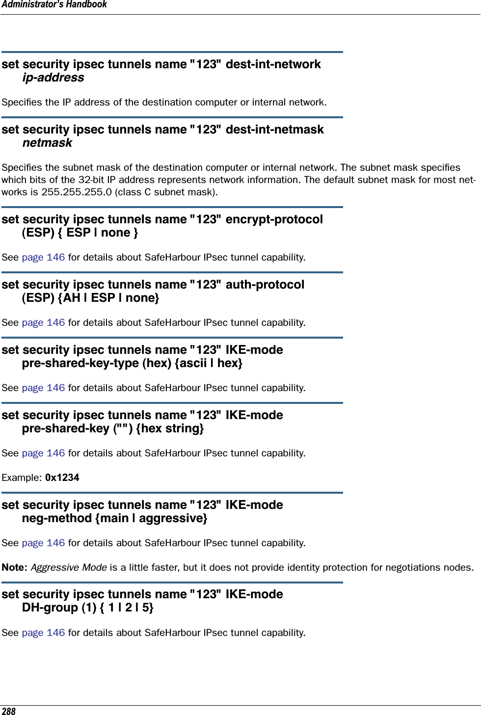
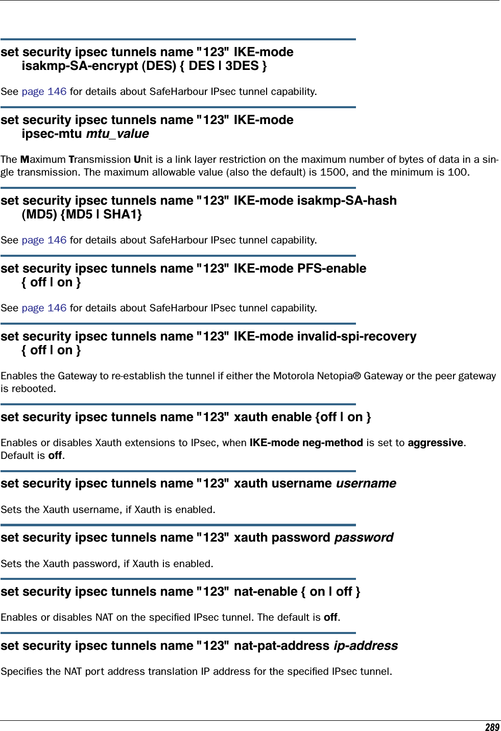
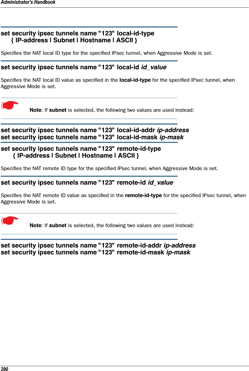
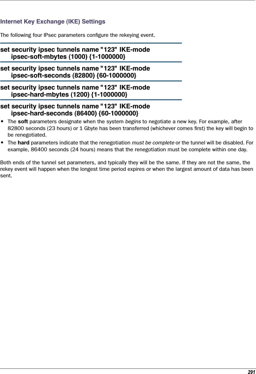
![Administrator’s Handbook292Stateful InspectionStateful inspection options are accessed by the security state-insp tag.set security state-insp [ ip-ppp | dsl ] vccn option [ off | on ]set security state-insp ethernet [ A | B ] option [ off | on ]Sets the stateful inspection option off or on on the specified interface. This option is disabled by default. Stateful inspection prevents unsolicited inbound access when NAT is disabled.set security state-insp [ ip-ppp | dsl ] vccn default-mapping [ off | on ]set security state-insp ethernet [ A | B ] default-mapping [ off | on ]Sets stateful inspection default mapping to router option off or on on the specified interface.set security state-insp [ ip-ppp | dsl ] vccn tcp-seq-diff [ 0 - 65535 ]set security state-insp ethernet [ A | B ] tcp-seq-diff [ 0 - 65535 ]Sets the acceptable TCP sequence difference on the specified interface. The TCP sequence number differ-ence maximum allowed value is 65535. If the value of tcp-seq-diff is 0, it means that this check is dis-abled.set security state-insp [ ip-ppp | dsl ] vccn deny-fragments [ off | on ]set security state-insp ethernet [ A | B ] deny-fragments [ off | on ]Sets whether fragmented packets are allowed to be received or not on the specified interface.set security state-insp tcp-timeout [ 30 - 65535 ]Sets the stateful inspection TCP timeout interval, in seconds.set security state-insp udp-timeout [ 30 - 65535 ]Sets the stateful inspection UDP timeout interval, in seconds.set security state-insp dos-detect [ off | on ]Enables or disables the stateful inspection Denial of Service detection feature. If set to on, the device will monitor packets for Denial of Service (DoS) attack. Offending packets may be discarded if it is determined to be a DoS attack.](https://usermanual.wiki/ARRIS/224762/User-Guide-1097848-Page-292.png)
![293set security state-insp xposed-addr exposed-address# "n" Allows you to add an entry to the specified list, or, if the list does not exist, creates the list for the stateful inspection feature. xposed-addr settings only apply if NAT is off.Example:set security state-insp xposed-addr exposed-address# (?): 3232 has been added to the xposed-addr list.Sets the exposed list address number.set security state-insp xposed-addr exposed-address# "n" start-ip ip_addressSets the exposed list range starting IP address, in dotted quad format.set security state-insp xposed-addr exposed-address# "n" end-ip ip_addressSets the exposed list range ending IP address, in dotted quad format.32 exposed addresses can be created. The range for exposed address numbers are from 1 through 32.set security state-insp xposed-addr exposed-address# "n" protocol [ tcp | udp | both | any ]Sets the protocol for the stateful inspection feature for the exposed address list. Accepted values for proto-col are tcp, udp, both, or any.If protocol is not any, you can set port ranges:set security state-insp xposed-addr exposed-address# "n" start-port [ 1 - 65535 ]set security state-insp xposed-addr exposed-address# "n" end-port [ 1 - 65535 ]](https://usermanual.wiki/ARRIS/224762/User-Guide-1097848-Page-293.png)
![Administrator’s Handbook294Packet Filtering SettingsPacket Filtering has two parts:•Create/Edit/Delete Filter Sets, create/edit/delete rules to a Filter Set.•Associate a created Filter Set with a WAN or LAN interfaceSee “Packet Filter” on page 163 for more information.set security pkt-filter filterset filterset-name [ input_filter | output_filter ] index forward [ on | off ]Creates or edits a filter rule, specifying whether packets will be forwarded or not.☛ NOTE:If this is the first rule, it will create the filter-set called filterset-name, otherwise it will edit the filterset.If the index is not consecutive, the system will select the next consecutive index. If the index does not exist, a rule will be created. If a rule exists, the rule will be edited.set security pkt-filter filterset filterset-name [ input_filter | output_filter ] index idle-reset [ on | off ]Turns idle reset on or off for the specified filter rule. A match on this rule resets idle-timeout status and keeps the WAN connection alive. The default is off. For idle-reset to be displayed, forward must be enabled on a filter rule.set security pkt-filter filterset filterset-name [ input_filter | output_filter ] index frc-rte [ on | off ]Turns forced routing on or off for the specified filter rule. A match on this rule will force a route for packets. The default is off. For frc-rte to be displayed, forward must be enabled on a filter rule.set security pkt-filter filterset filterset-name [ input_filter | output_filter ] index gateway ip_addrSpecifies the gateway IP address for forced routed packets, if forced routing is enabled.set security pkt-filter filterset filterset-name [ input_filter | output_filter ] index src-ip ip_addrSpecifies the source IP address to match packets (where the packet was sent from).set security pkt-filter filterset filterset-name [ input_filter | output_filter ] index src-mask maskSpecifies the source IP mask to match packets (where the packet was sent from).](https://usermanual.wiki/ARRIS/224762/User-Guide-1097848-Page-294.png)
![295set security pkt-filter filterset filterset-name [ input_filter | output_filter ] index dest-ip ip_addrSpecifies the destination IP address to match packets (where the packet is going).set security pkt-filter filterset filterset-name [ input_filter | output_filter ] index dest-mask maskSpecifies the destination IP mask to match packets (where the packet is going).set security pkt-filter filterset filterset-name [ input_filter | output_filter ] index tos valueSpecifies the TOS (Type Of Service) value to match packets. The value for tos can be from 0 – 255.set security pkt-filter filterset filterset-name [ input_filter | output_filter ] index tos-mask valueSpecifies the TOS (Type Of Service) mask to match packets. The value for tos-mask can be from 0 – 255.set security pkt-filter filterset filterset-name [ input_filter | output_filter ] index protocol valueSpecifies the protocol value to match packets, the type of higher-layer Internet protocol the packet is carry-ing, such as TCP or UDP. The value for protocol can be from 0 – 255.set security pkt-filter filterset filterset-name [ input_filter | output_filter ] index src-compare [ nc | ne | lt | le | eq | gt | ge ]Sets the source compare operator action for the specified filter rule. src-compare only displays when the protocol is TCP or UDP.Operator Actionnc No comparene Not equal tolt Less thanle Less than or equal toeq Equal toge Greater than or equal togt Greater than](https://usermanual.wiki/ARRIS/224762/User-Guide-1097848-Page-295.png)
![Administrator’s Handbook296set security pkt-filter filterset filterset-name [ input_filter | output_filter ] index dst-compare [ nc | ne | lt | le | eq | gt | ge ]Sets the destination compare operator action for the specified filter rule. dst-compare only displays when the protocol is TCP or UDP.set security pkt-filter filterset filterset-name [ input_filter | output_filter ] index src-port valueSpecifies the source IP port to match packets (the port on the sending host that originated the packet, if the underlying protocol is TCP or UDP). src-port does not display if nc is set for src-compare or dst-com-pare.set security pkt-filter filterset filterset-name [ input_filter | output_filter ] index dst-port valueSpecifies the destination IP port to match packets (the port on the receiving host that the packet is des-tined for, if the underlying protocol is TCP or UDP). dst-port does not display if nc is set for src-compare or dst-compare.set security pkt-filter interface assigned-filterset filterset-nameAssociates a filterset with a LAN or WAN interface.Example:set security pkt-filter ethernet A assigned-filterset set1Operator Actionnc No comparene Not equal tolt Less thanle Less than or equal toeq Equal toge Greater than or equal togt Greater than](https://usermanual.wiki/ARRIS/224762/User-Guide-1097848-Page-296.png)
![297SNMP SettingsThe Simple Network Management Protocol (SNMP) lets a network administrator monitor problems on a net-work by retrieving settings on remote network devices. The network administrator typically runs an SNMP management station program on a local host to obtain information from an SNMP agent such as the Motor-ola Netopia® Gateway.set snmp community read nameAdds the specified name to the list of communities associated with the Motorola Netopia® Gateway. By default, the Motorola Netopia® Gateway is associated with the public community.set snmp community write nameAdds the specified name to the list of communities associated with the Motorola Netopia® Gateway.set snmp community trap nameAdds the specified name to the list of communities associated with the Motorola Netopia® Gateway.set snmp trap ip-traps ip-addressIdentifies the destination for SNMP trap messages. The ip-address argument is the IP address of the host acting as an SNMP console.set snmp sysgroup contact contact_infoIdentifies the system contact, such as the name, phone number, beeper number, or email address of the person responsible for the Motorola Netopia® Gateway. You can enter up to 255 characters for the contact_info argument. You must put the contact_info argument in double-quotes if it contains embedded spaces.set snmp sysgroup location location_infoIdentifies the location, such as the building, floor, or room number, of the Motorola Netopia® Gateway. You can enter up to 255 characters for the location_info argument. You must put the location_info argument in double-quotes if it contains embedded spaces.SNMP Notify Type Settingsset snmp notify type [ v1-trap | v2-trap | inform ]Sets the type of SNMP notifications that the system will generate: •v1-trap – This selection will generate notifications containing an SNMPv1 Trap Protocol Data Unit (PDU)•v2-trap – This selection will generate notifications containing an SNMPv2 Trap PDU•inform – This selection will generate notifications containing an SNMPv2 InformRequest PDU.](https://usermanual.wiki/ARRIS/224762/User-Guide-1097848-Page-297.png)
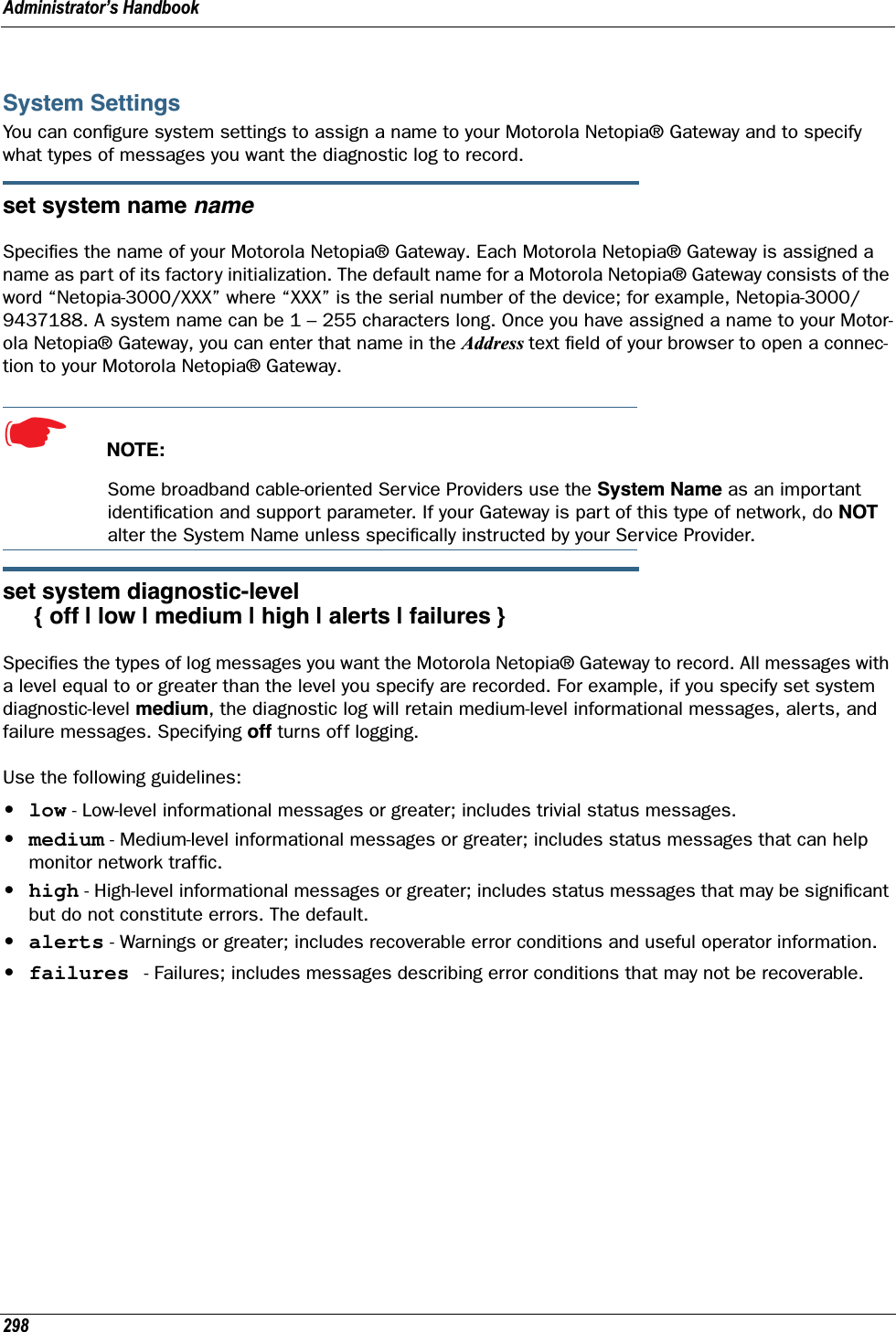
![299set system ftp-server option [ off | on ]Enables or disables a simple FTP server in the Gateway. If enabled, the Gateway will accept binary embed-ded software images (‘.bin’) files or command line configuration files.set system log-size [ 10240... 65536 ]Specifies a size for the system log. The most recent entries are posted to the beginning of the log. When the log becomes full, the oldest entries are dropped. The default is 30000.set system persistent-log [ off | on ]When set to on, causes the log information to be kept in flash memory.set system idle-timeout { telnet [ 1...120 ] | http [ 1... 120 ] }Specifies a timeout period of inactivity for telnet or HTTP access to the Gateway, after which a user must re-login to the Gateway. Defaults are 5 minutes for HTTP and 15 minutes for telnet.set system username { administrator name | user name }Specifies the usernames for the administrative user – the default is admin; and a non-administrative user – the default is user.set system password { admin | user }Specifies the administrator or user password for a Motorola Netopia® Gateway. When you enter the set system password command, you are prompted to enter the old password (if any) and new password. You are prompted to repeat the new password to verify that you entered it correctly the first time. To prevent anyone from observing the password you enter, characters in the old and new passwords are not displayed as you type them. For security, you cannot use the “step” method to set the system password.A password can be as many as 8 characters. Passwords are case-sensitive. Passwords go into effect immediately. You do not have to restart the Motorola Netopia® Gateway for the password to take effect. Assigning an administrator or user password to a Motorola Netopia® Gateway does not affect communications through the device. Supported FTP commandsMODE (data transfer mode (only Streaming supported)NOOP (send back ok)PORT (specify client address:port for data)QUIT (quit)STOR (send file to FTP server)SYST (get system info about FTP server)TYPE (set data representation type, ASCII and IMAGE (BIN) only supported)USER (send username for authentication)](https://usermanual.wiki/ARRIS/224762/User-Guide-1097848-Page-299.png)
![Administrator’s Handbook300set system heartbeat option { on | off } protocol [ udp | tcp ] port-client [ 1 - 65535 ] ip-server [ ip_address | dns_name ] port-server [ 1 - 65535 ] url-server ("server_name") number [ 1 – 1073741823 ] interval (00:00:00:20) sleep (00:00:30:00) contact-email ("string@domain_name") location ("string"):The heartbeat setting is used in conjunction with the configuration server to broadcast contact and location information about your Gateway. You can specify the protocol, port, IP-, port-, and URL-server. •The interval setting specifies the broadcast update frequency. Part of sequence control. The interval is the spacing between heartbeats, in d:h:m:s.•The contact-email setting is a quote-enclosed text string giving an email address for the Gateway’s administrator. •The location setting is a text string allowing you to specify your geographical or other location, such as “Secaucus, NJ.”• The number setting is part of the sequence control. This is the number of heartbeats to send, at each “interval”, before sleeping. For example, if this is 20, in the above layout, each heartbeat sequence will send out a total 20 heartbeats, spaced at 30 second intervals, and then sleep for 30 minutes. So to have the Gateway send out packets “forever”, this number can be set very high. If it is 1440 and the interval is 1 minute, say, the heartbeat will go out every minute for 1440 minutes, or one day, before sleeping.•The sleep setting is part of sequence control. This is the time to sleep before starting another heart-beat sequence, in d:h:m:s.set system ntp option [ off | on ]:server-address (north-america.pool.ntp.org)alt-server-address (pool.ntp.org):time-zone [ -12 - 12 ] update-period (60) [ 1 - 65535 ]: daylight-savings [ off | on ]Specifies the NTP server address, time zone, and how often the Gateway should check the time from the NTP server. The NTP server-address and alt-server-address can be entered as DNS names as well as IP addresses. NTP time-zone of 0 is GMT time; options are -12 through 12 (+/- 1 hour increments from GMT time). update-period specifies how often, in minutes, the Gateway should update the clock. daylight-sav-ings specifies whether daylight savings time is in effect; it defaults to off.set system zerotouch option [ on | off ]Enables or disables the Zero Touch option.](https://usermanual.wiki/ARRIS/224762/User-Guide-1097848-Page-300.png)
![301Zero Touch refers to automatic configuration of your Motorola Netopia® Gateway. The Motorola Netopia® Gateway has default settings such that initial connection to the Internet will succeed. If the zerotouch option is set to on, HTTP requests to any destination IP address except the IP address(es) of the configured redirection URL(s) will access a redirection server. DNS traffic will not be blocked. Other traffic from the LAN to all destinations will be dropped.set system zerotouch redirect-url redirection-URLSpecifies the URL(s) of the desired redirection server(s) when the zerotouch option is set to on. URLs may be a maximum of 192 characters long, and may be in any of the following forms:http://<domain-name OR IP address>/optionalPath:porthttp://<domain-name OR IP address>/optionalPathhttps://<domain-name OR IP address>/optionalPath:porthttps://<domain-name OR IP address>/optionalPath<domain-name OR IP address>/optionalPath:port<domain-name OR IP address>/optionalPathIf the port number is omitted, port 80 will be assumed.Syslogset system syslog option [ off | on ]Enables or disables system syslog feature. If syslog option is on, the following commands are available:set system syslog host-nameip [ ip_address | hostname ]Specifies the syslog server’s address either in dotted decimal format or as a DNS name up to 64 charac-ters.set system syslog log-facility [ local0 ... local7 ]Sets the UNIX syslog Facility. Acceptable values are local0 through local7.set system syslog log-violations [ off | on ]Specifies whether violations are logged or ignored.set system syslog log-accepted [ off | on ]Specifies whether acceptances are logged or ignored.set system syslog log-attempts [ off | on ]Specifies whether connection attempts are logged or ignored.](https://usermanual.wiki/ARRIS/224762/User-Guide-1097848-Page-301.png)
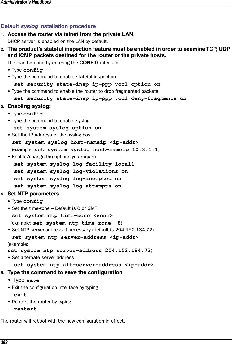
![Administrator’s Handbook304set wireless multi-ssid {second-ssid | third-ssid | fourth-ssid } nameSpecifies a descriptive name for each SSID. when multi-ssid option is set to on.set wireless multi-ssid second-ssid-privacy { off | WEP | WPA-PSK | WPA-802.1x }set wireless multi-ssid third-ssid-privacy { off | WEP | WPA-PSK | WPA-802.1x }set wireless multi-ssid fourth-ssid-privacy { off | WEP | WPA-PSK | WPA-802.1x }Specifies the type of privacy enabled on multiple SSIDs when multi-ssid option is set to on. off = no pri-vacy; WEP = WEP encryption; WPA-PSK = Wireless Protected Access/Pre-Shared Key; WPA-802.1x = Wire-less Protected Access/802.1x authentication. See “Wireless Privacy Settings” on page 308 for more information.☛ NOTE:WEP is supported on only one SSID at a time, and will not be available if another SSID already has it configured.set wireless multi-ssid second-ssid-wpa-ver { all | WPA1-only | WPA2-only }set wireless multi-ssid third-ssid-wpa-ver { all | WPA1-only | WPA2-only }set wireless multi-ssid fourth-ssid-wpa-ver { all | WPA1-only | WPA2-only }Specifies the type of WPA version enabled on multiple SSIDs when multi-ssid option is set to on and pri-vacy is set tp WPA-PSK. See “Wireless Privacy Settings” on page 308 for more information.set wireless multi-ssid second-ssid-psk { string }set wireless multi-ssid third-ssid-psk { string }set wireless multi-ssid fourth-ssid-psk { string }Specifies a WPA passphrase for the multiple SSIDs, when second-, third-, or fourth-ssid-privacy is set to WPA-PSK. The Pre Shared Key is a passphrase shared between the Gateway and the clients and is used to generate dynamically changing keys. The passphrase can be 8 – 63 characters. It is recommended to use at least 20 characters for best security.set wireless multi-ssid second-ssid-weplen [ 40/64bit | 128bit | 256bit ]set wireless multi-ssid third-ssid-weplen [ 40/64bit | 128bit | 256bit ]set wireless multi-ssid fourth-ssid-weplen [ 40/64bit | 128bit | 256bit ]Specifies the WEP key length for the multiple SSIDs, when second-, third-, or fourth-ssid-privacy is set to WEP. 40bit encryption is equivalent to 64bit encryption. The longer the key, the stronger the encryption and the more difficult it is to break the encryption.](https://usermanual.wiki/ARRIS/224762/User-Guide-1097848-Page-304.png)
![305set wireless multi-ssid second-ssid-wepkey { hexadecimal digits }set wireless multi-ssid third-ssid-wepkey { hexadecimal digits }set wireless multi-ssid fourth-ssid-wepkey { hexadecimal digits }Specifies a WEP key for the multiple SSIDs, when second-, third-, or fourth-ssid-privacy is set to WEP. For 40/64bit encryption, you need 10 digits; 26 digits for 128bit, and 58 digits for 256bit WEP. Valid hexa-decimal characters are 0 – 9, a – f. set wireless no-bridging [ off | on ]When set to on, this will block wireless clients from communicating with other wireless clients on the LAN side of the Gateway.set wireless tx-power [ full | medium | fair | low | minimal ]Sets the wireless transmit power, scaling down the router's wireless transmit coverage by lowering its radio power output. Default is full power. Transmit power settings are useful in large venues with multiple wire-less routers where you want to reuse channels. Since there are only three non-overlapping channels in the 802.11 spectrum, it helps to size the Gateway’s cell to match the location. This allows you to install a router to cover a small “hole” without conflicting with other routers nearby.](https://usermanual.wiki/ARRIS/224762/User-Guide-1097848-Page-305.png)
![Administrator’s Handbook306Wireless Multi-media (WMM) SettingsRouter EDCA Parameters (Enhanced Distributed Channel Access) govern wireless data from your Gate-way to the client; Client EDCA Parameters govern wireless data from the client to your Gateway.set wireless wmm option [ off | on ]Enables or disables wireless multi-media settings option, which allows you to fine tune WiFi Multimedia Quality of Service (QoS) by transmitting data depending on Diffserv priority settings. These priorities are mapped into four Access Categories (AC), in increasing order of priority: Background (BK), Best Effort (BE), Video (VI), and Voice (VO). It requires WiFi Multimedia-capable clients, usually a separate feature enabled at the client.•aifs: (Arbitration Interframe Spacing) the wait time in milliseconds for data frames.Valid values are: 1 – 255•cwmin: (Minimum Contention Window) upper limit in milliseconds of the range for determining initial random backoff. The value you choose must be lower than cwmax.Valid values are: 1, 3, 7, 15, 31, 63, 127, 255, or 511. •cwmax: (Maximum Contention Window) upper limit in milliseconds of the range of determining final ran-dom backoff. The value you choose must be higher than cwmin.Valid values are: 3, 7, 15, 31, 63, 127, 255, 511, or 1023.•txoplimit: Time interval in microseconds that clients may initiate transmissions. Valid values are: 0 – 9999.☛ NOTE:It is not recommended that you modify these settings without direct knowledge or instructions to do so. Modifying these settings inappropriately could seriously degrade network perfor-mance.set wireless wmm router-edca voice { aifs 1... 255 } set wireless wmm router-edca voice { cwmin value } set wireless wmm router-edca voice { cwmax value }Sets values for Gateway WMM voice parameters.set wireless wmm router-edca video { aifs 1... 255 } set wireless wmm router-edca video { cwmin value } set wireless wmm router-edca video { cwmax value }Sets values for Gateway WMM video parameters.set wireless wmm router-edca best-effort { aifs 1... 255 } set wireless wmm router-edca best-effort { cwmin value } set wireless wmm router-edca best-effort { cwmax value }Sets values for Gateway WMM best effort parameters.](https://usermanual.wiki/ARRIS/224762/User-Guide-1097848-Page-306.png)
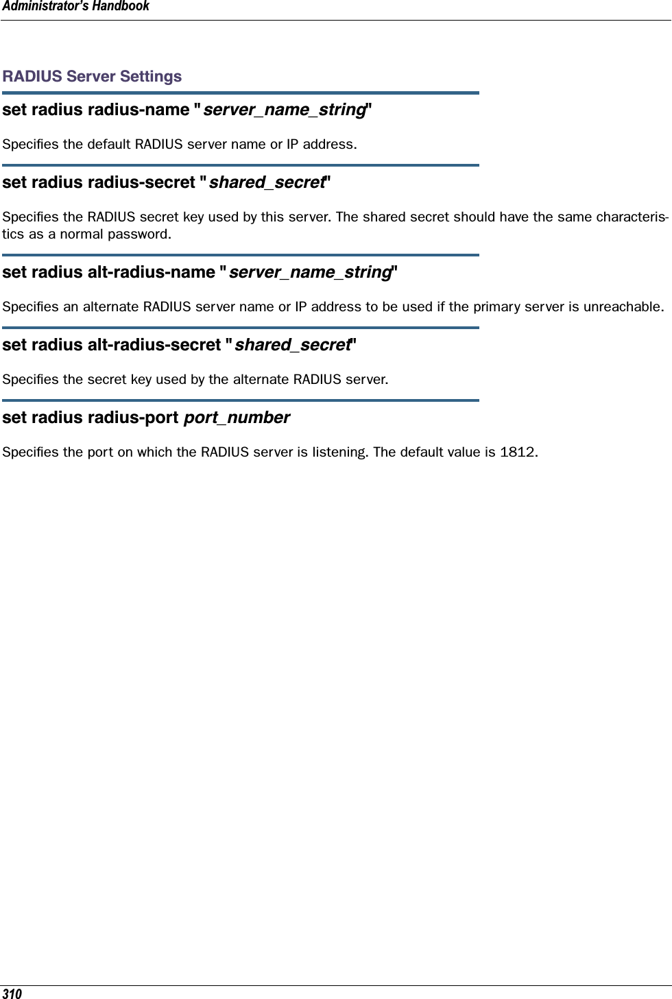
![311VLAN SettingsYou can create up to 8 VLANs, and you can also restrict any VLAN, and the computers on it, from adminis-tering the Gateway. See “VLAN” on page 107 for more information.set vlan name nameSets the descriptive name for the VLAN. If no name is specified, displays a selection list of node names to select for editing. Once a new VLAN name is specified, presents the list of VLAN characteristics to define.set vlan name name type [ by-port | global ]Specifies VLAN type: by-port or global. Default is by-port.set vlan name name id VIDSpecifies VLAN id (VID), when type is set to global. The numerical range of possible VIDs is 1 - 4094. (A VID of zero (0) is permitted on the Ethernet WAN port only.)set vlan name name admin-restricted [ off | on ]Turns admin-restricted off or on. Default is off. If you select on, administrative access to the Gateway is blocked from the specified VLAN.set vlan name name seg-pbits [ 0 - 7 ]Specifies the 802.1p priority bit. If you set this to a value greater than 0, all packets of this VLAN with unmarked priority bits (pbits) will be re-marked to this priority.set vlan name name ports port option [ off | on ]Enables or disables the Gateway’s physical Ethernet, USB or VCC port or wireless SSID for the specified VLAN.set vlan name name ports port tag [ off | on ]If set to on, packets transmitted from this port through this VLAN must be tagged with the VLAN VID. Pack-ets received through this port destined for this VLAN must be tagged with the VLAN VID by the source. The tag option is only available on global type ports.set vlan name name ports port priority [ off | on ]Enables or disables the priority for the port assigned to the specified VLAN allowing packet prioritization based on any 802.1p priority bits in the VLAN header to prioritize packets within the Gateway’s internal queues, according to DiffServ priority mapping rules.set vlan name name ports port promote [ off | on ]Enables or disables the promote setting allowing writing any 802.1p priority bits into the IP-TOS header bit field for received IP packets on this port destined for this VLAN. Write any IP-TOS priority bits into the](https://usermanual.wiki/ARRIS/224762/User-Guide-1097848-Page-311.png)
![Administrator’s Handbook312802.1p priority bit field for tagged IP packets transmitted from this port for this VLAN. All mappings between Ethernet 802.1p and IP-TOS are made via diffserv dscp-map settings.set vlan name name ports port port-pbits [ 0 - 7 ]Specifies the 802.1p priority bit for this port associated with the specified VLAN. If you set this to a value greater than 0, all packets of this port with unmarked priority bits (pbits) will be re-marked to this priority.set vlan name name ip-interface ip_interfaceAssociates this VLAN with the specified IP interface. By default the ip-vcc1 and ip-eth-a interfaces are available, but others may be defined.set vlan name name inter-vlan-routing [ group-1... group-8 ] [ off | on ]When set to on, inter-vlan-routing allows VLANs in the specified group to route traffic to the others; ungrouped VLANs cannot route traffic to each other.You must save the changes, exit out of configuration mode, and restart the Gateway for the changes to take effect.Example 1:•A simple example using the “Step” method – Navigate to the VLAN item:Netopia-3000/9437188 (top)>> vlanNetopia-3000/9437188 (vlan)>> set vlan(vlan) node list ...Select (name) node to modify from list,or enter new (name) to create. vlan name (?): vlan1(vlan1) has been added to the (vlan) list name "vlan1" type (by-port) [ by-port | global ]: by-port admin-restricted (off) [ off | on ]: off seg-pbits (0) [ 0 - 7 ]: 0 ports•At this point you have created a VLAN. It is called vlan1, without any admin restrictions.•Next, add the port eth0.1 port to this VLAN: ports eth0.1 option (off) [ off | on ]: on priority (off) [ off | on ]: on promote (off) [ off | on ]: on port-pbits (0) [ 0 - 7 ]: 1 eth0.2 option (off) [ off | on ]: eth0.3 option (off) [ off | on ]: eth0.4 option (off) [ off | on ]: ssid1](https://usermanual.wiki/ARRIS/224762/User-Guide-1097848-Page-312.png)
![313 option (off) [ off | on ]: vcc1 option (off) [ off | on ]:•Assign an IP interface: ip-vcc1 option (off) [ off | on ]: ip-eth-a option (off) [ off | on ]: on ipsec-mgmt1 option (off) [ off | on ]:Netopia-3000/9437188 (vlan)>>Example 2:•An example of a “Triple-Play” setup:set vlan name "LanPorts" type by-portset vlan name "LanPorts" admin-restricted offset vlan name "LanPorts" seg-pbits 0set vlan name "LanPorts" ports eth0.1 option offset vlan name "LanPorts" ports eth0.2 option onset vlan name "LanPorts" ports eth0.2 priority offset vlan name "LanPorts" ports eth0.2 promote offset vlan name "LanPorts" ports eth0.2 port-pbits 0set vlan name "LanPorts" ports eth0.3 option onset vlan name "LanPorts" ports eth0.3 priority offset vlan name "LanPorts" ports eth0.3 promote offset vlan name "LanPorts" ports eth0.3 port-pbits 0set vlan name "LanPorts" ports eth0.4 option onset vlan name "LanPorts" ports eth0.4 priority offset vlan name "LanPorts" ports eth0.4 promote offset vlan name "LanPorts" ports eth0.4 port-pbits 0set vlan name "LanPorts" ports ssid1 option onset vlan name "LanPorts" ports ssid1 priority offset vlan name "LanPorts" ports ssid1 promote offset vlan name "LanPorts" ports ssid1 port-pbits 0set vlan name "LanPorts" ports eth1 option offset vlan name "LanPorts" ip-interfaces ip-ppp-a option off set vlan name "LanPorts" ip-interfaces ip-eth-b option offset vlan name "LanPorts" ip-interfaces ip-eth-c option offset vlan name "LanPorts" ip-interfaces ip-eth-a option onset vlan name "LanPorts" inter-vlan-routing group-1 onset vlan name "LanPorts" inter-vlan-routing group-2 offset vlan name "LanPorts" inter-vlan-routing group-3 offset vlan name "LanPorts" inter-vlan-routing group-4 offset vlan name "Voip_217" type globalset vlan name "Voip_217" id 217set vlan name "Voip_217" admin-restricted offset vlan name "Voip_217" seg-pbits 7set vlan name "Voip_217" ports eth0.1 option offset vlan name "Voip_217" ports eth0.2 option offset vlan name "Voip_217" ports eth0.3 option offset vlan name "Voip_217" ports eth0.4 option offset vlan name "Voip_217" ports ssid1 option offset vlan name "Voip_217" ports eth1 option onset vlan name "Voip_217" ports eth1 tag onset vlan name "Voip_217" ports eth1 priority offset vlan name "Voip_217" ports eth1 promote offset vlan name "Voip_217" ports eth1 port-pbits 0set vlan name "Voip_217" ip-interfaces ip-ppp-a option off set vlan name "Voip_217" ip-interfaces ip-eth-b option onset vlan name "Voip_217" ip-interfaces ip-eth-c option off](https://usermanual.wiki/ARRIS/224762/User-Guide-1097848-Page-313.png)
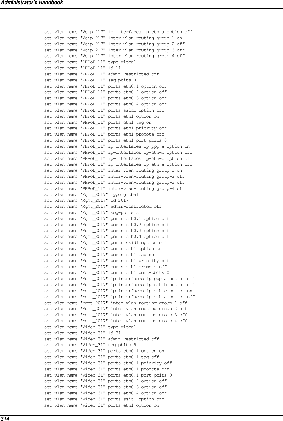
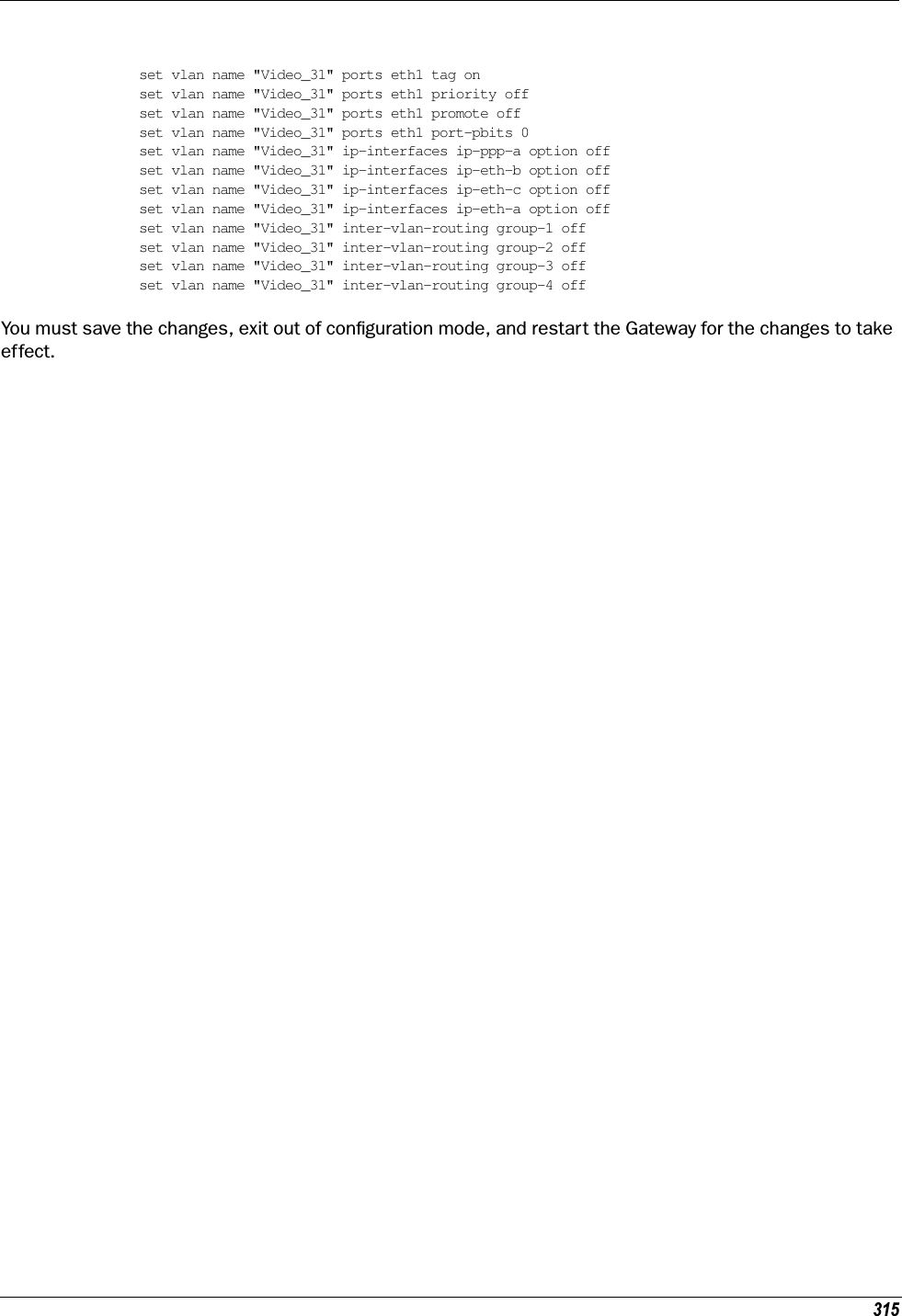
![Administrator’s Handbook316VoIP settings(supported models only)Voice-over-IP (VoIP) refers to the ability to make voice telephone calls over the Internet. This differs from tra-ditional phone calls that use the Public Switched Telephone Network (PSTN). VoIP calls use an Internet pro-tocol, Session Initiation Protocol (SIP), to transmit sound over a network or the Internet in the form of data packets. Certain Motorola Netopia® Gateway models have two separate voice ports for connecting tele-phone handsets. These models support VoIP. If your Gateway is a VoIP model, you can configure the VoIP features.set voip phone [ 0 | 1 ] sip-option [ off | on ]Turns SIP on or off for the specified phone. Default is off.set voip phone [ 0 | 1 ] sip-proxy-server [ server_name | ip_address ]Specifies the SIP proxy server for the specified phone by fully qualified server name or IP address.set voip phone [ 0 | 1 ] sip-proxy-server-domain domain_nameSpecifies the SIP proxy server domain name or IP address for the specified phone.set voip phone [ 0 | 1 ] sip-proxy-server-transport [ UDP | TCP | TLS ]Specifies the SIP proxy server transport protocol for the specified phone. Default is UDP.set voip phone [ 0 | 1 ] sip-registrar-setting sip-registrar-server [ server_name | ip_address ]Specifies the SIP registration server for the specified phone by fully qualified server name or IP address.set voip phone [ 0 | 1 ] sip-registrar-setting sip-registrar-server-transport [ UDP | TCP | TLS ]Specifies the SIP registration server transport protocol for the specified phone . Default is UDP.set voip phone [ 0 | 1 ] sip-registrar-setting sip-expires-time [ 0 - 65535 ]Specifies the SIP registration server time-out duration from 0 – 65535 seconds for the specified phone. Default is 3600 (1 hour).set voip phone [ 0 | 1 ] sip-out-proxy-server [ server_name | ip_address ]Specifies the SIP outbound proxy server for the specified phone by fully qualified server name or IP address.](https://usermanual.wiki/ARRIS/224762/User-Guide-1097848-Page-316.png)
![317set voip phone [ 0 | 1 ] sip-user-display-name nameSpecifies the user name that is displayed on the web UI Home page, or other caller-id displays for the spec-ified phone.set voip phone [ 0 | 1 ] sip-user-name usernameSpecifies the user name that authenticates the user to SIP for the specified phone.set voip phone [ 0 | 1 ] sip-user-password passwordSpecifies the password that authenticates the user to SIP for the specified phone.set voip phone [ 0 | 1 ] auth-id stringSpecifies the authorization ID that authenticates the user to SIP for the specified phone. Most SIP Servers expect this to be the username itself but some may use auth-id.set voip phone [ 0 | 1 ] codec G711A priority [ 1 | 2 | 3 | 4 | 5 | 6 | 7 | none ]Assigns a priority to the alaw codec, the common analog voice encoding method used outside North Amer-ica.set voip phone [ 0 | 1 ] codec G711U priority [ 1 | 2 | 3 | 4 | 5 | 6 | 7 | none ]Assigns a priority to the ulaw codec, the common analog voice encoding method used in North America.set voip phone [ 0 | 1 ] codec G729A priority [ 1 | 2 | 3 | 4 | 5 | 6 | 7 | none ]Assigns a priority to the G729 annex A codec, the common analog voice compression implementation used in North America.set voip phone [ 0 | 1 ] codec G726_16 priority [ 1 | 2 | 3 | 4 | 5 | 6 | 7 | none ]Assigns a priority to the G726-16 codec, a common audio media type implementation at 16 kbit/s.set voip phone [ 0 | 1 ] codec G726_24 priority [ 1 | 2 | 3 | 4 | 5 | 6 | 7 | none ]Assigns a priority to the G726-24 codec, a common audio media type implementation at 24 kbit/s.set voip phone [ 0 | 1 ] codec G726_32 priority [ 1 | 2 | 3 | 4 | 5 | 6 | 7 | none ]Assigns a priority to the G726-32 codec, a common audio media type implementation at 32 kbit/s.](https://usermanual.wiki/ARRIS/224762/User-Guide-1097848-Page-317.png)
![Administrator’s Handbook318set voip phone [ 0 | 1 ] codec G726_40 priority [ 1 | 2 | 3 | 4 | 5 | 6 | 7 | none ]Assigns a priority to the G726-40 codec, a common audio media type implementation at 40 kbit/s.set voip phone [ 0 | 1 ] sip-advanced-setting sip-dtmf-mode [ inband | rfc2833 | info ]sip-dtmf-mode – sets the Dual Tone Multi-Frequency Mode:•inband: sends the DTMF digits as a normal inband tone.•rfc2833: sends the DTMF digits as an event as part of the RTP packet header information.•info: sends the DTMF digits in the SIP INFO message.set voip phone [ 0 | 1 ] sip-advanced-setting sip-end-of-dial-marker [ off | on ]sip-end-of-dial-marker – turns an “end of dial” (#) signal that indicates that the dialed number is com-plete on or off.set voip phone [ 0 | 1 ] sip-advanced-setting call-feature call-forwarding-all-option [ off | on ]call-forwarding-all-option – turns unconditional call forwarding on or off.set voip phone [ 0 | 1 ] sip-advanced-setting call-feature call-forwarding-all-number phone_numbercall-forwarding-all-number – specifies the number to which calls are to be forwarded when call-forward-ing-all-option is on.set voip phone [ 0 | 1 ] sip-advanced-setting call-feature call-forwarding-on-busy-option [ off | on ]call-forwarding-on-busy-option – turns call forwarding when the line is busy on or off.set voip phone [ 0 | 1 ] sip-advanced-setting call-feature call-forwarding-on-no-answer-option [ off | on ]call-forwarding-on-no-answer-option – turns call forwarding when there is no answer on or off.set voip phone [ 0 | 1 ] sip-advanced-setting call-feature call-forwarding-on-no-answer-number phone_numbercall-forwarding-on-no-answer-number – specifies the number to which calls are to be forwarded when call-forwarding-on-no-answer-option is on.](https://usermanual.wiki/ARRIS/224762/User-Guide-1097848-Page-318.png)
![319set voip phone [ 0 | 1 ] sip-advanced-setting call-feature call-waiting-option [ off | on ]call-waiting-option – enables or disables call waiting.set voip phone [ 0 | 1 ] sip-advanced-setting call-feature call-conferencing-option [ off | on ]call-conferencing-option – enables or disables 3-way call conferencing.set voip phone [ 0 | 1 ] sip-advanced-setting call-feature subscribe-do-not-disturb-option [ off | on ]subscribe-do-not-disturb-option – enables or disables option to prevent the phone from ringing.set voip phone [ 0 | 1 ] sip-advanced-setting call-feature subscribe-mwi-option [ off | on ]subscribe-mwi-option – if set to on, the Message Waiting Indicator is enabled when new voice mail is received.set voip phone [ 0 | 1 ] sip-advanced-setting dsp-settings echo-option [ echo-off | echo-on | echo-on-nlp | echo-on-cng-nlp ]echo-option – specifies under what conditions the system invokes or disables echo cancellation. Default is echo-on-cng-nlp (Comfort Noise Generation with non-linear processor).set voip phone [ 0 | 1 ] sip-advanced-setting dsp-settings echo-start-attenuation [ 0 - 65535 ]echo-start-attenuation – specifies the minimum attenuation level at which to invoke echo cancellation. Default is 8192.set voip phone [ 0 | 1 ] sip-advanced-setting dsp-settings echo-max-attenuation [ 0 - 65535 ]echo-max-attenuation – specifies the maximum attenuation level at which to invoke echo cancellation. Default is 16384.set voip phone [ 0 | 1 ] sip-advanced-setting dsp-settings echo-tail-length [ 0 - 65535 ]echo-tail-length – specifies the duration of an echo tail required to invoke cancellation. Default is 0.set voip phone [ 0 | 1 ] sip-advanced-setting dsp-settings vad-option [ off | on ]vad-option – turns Voice Activity Detection on or off. Default is off.](https://usermanual.wiki/ARRIS/224762/User-Guide-1097848-Page-319.png)
![Administrator’s Handbook320set voip phone [ 0 | 1 ] sip-advanced-setting dsp-settings vad-setting [ vad-cn | vad-std-sid | vad-suppress-sid ]When vad-option is set to on:•vad-cn – enables Voice Activity Detection/Comfort Noise Generation. When speech is not present, the CNG algorithm generates a noise signal at the level sent from the transmit side.•vad-std-sid – enables Voice Activity Detection with standard Silence Insertion Descriptor support.•vad-suppress-sid – enables Voice Activity Detection but suppresses standard Silence Insertion Descriptor support.Exampleset voip phone: 0 sip-option onset voip phone: 0 sip-proxy-server "10.3.1.129"set voip phone: 0 sip-proxy-server-domain ""set voip phone: 0 sip-proxy-server-transport UDPset voip phone: 0 sip-registrar-setting sip-registrar-server "10.3.1.129"set voip phone: 0 sip-registrar-setting sip-registrar-server-transport UDPset voip phone: 0 sip-registrar-setting sip-expires-time 3600set voip phone: 0 sip-out-proxy-server "10.3.1.129"set voip phone: 0 sip-user-display-name "4004"set voip phone: 0 sip-user-name "4004"set voip phone: 0 sip-user-password "4004"set voip phone: 0 auth-id "4004"set voip phone: 0 codec G711A priority 1set voip phone: 0 codec G711U priority 2set voip phone: 0 codec G729A priority 3set voip phone: 0 codec G726_16 priority 4set voip phone: 0 codec G726_24 priority 5set voip phone: 0 codec G726_32 priority 6set voip phone: 0 codec G726_40 priority 7set voip phone: 0 sip-advanced-setting sip-dtmf-mode rfc2833set voip phone: 0 sip-advanced-setting sip-end-of-dial-marker offset voip phone: 0 sip-advanced-setting call-feature call-forwarding-all-option offset voip phone: 0 sip-advanced-setting call-feature call-forwarding-on-busy-option offset voip phone: 0 sip-advanced-setting call-feature call-forwarding-on-no-answer-option offset voip phone: 0 sip-advanced-setting call-feature call-waiting-option offset voip phone: 0 sip-advanced-setting call-feature call-conferencing-option offset voip phone: 0 sip-advanced-setting call-feature subscribe-do-not-disturb-option offset voip phone: 0 sip-advanced-setting call-feature subscribe-mwi-option offset voip phone: 0 sip-advanced-setting dsp-settings echo-option echo-on-cng-nlpset voip phone: 0 sip-advanced-setting dsp-settings echo-start-attenuation 8192set voip phone: 0 sip-advanced-setting dsp-settings echo-max-attenuation 16384set voip phone: 0 sip-advanced-setting dsp-settings echo-tail-length 0set voip phone: 0 sip-advanced-setting dsp-settings vad-option offset voip phone: 1 sip-option onset voip phone: 1 sip-proxy-server "10.3.1.129"set voip phone: 1 sip-proxy-server-domain ""set voip phone: 1 sip-proxy-server-transport UDPset voip phone: 1 sip-registrar-setting sip-registrar-server "10.3.1.129"set voip phone: 1 sip-registrar-setting sip-registrar-server-transport UDPset voip phone: 1 sip-registrar-setting sip-expires-time 3600set voip phone: 1 sip-out-proxy-server "10.3.1.129"set voip phone: 1 sip-user-display-name "4005"set voip phone: 1 sip-user-name "4005"set voip phone: 1 sip-user-password "4005"set voip phone: 1 auth-id "4005"set voip phone: 1 codec G711A priority 1](https://usermanual.wiki/ARRIS/224762/User-Guide-1097848-Page-320.png)
![321set voip phone: 1 codec G711U priority 2set voip phone: 1 codec G729A priority 3set voip phone: 1 codec G726_16 priority 4set voip phone: 1 codec G726_24 priority 5set voip phone: 1 codec G726_32 priority 6set voip phone: 1 codec G726_40 priority 7set voip phone: 1 sip-advanced-setting sip-dtmf-mode rfc2833set voip phone: 1 sip-advanced-setting sip-end-of-dial-marker offset voip phone: 1 sip-advanced-setting call-feature call-forwarding-all-option offset voip phone: 1 sip-advanced-setting call-feature call-forwarding-on-busy-option offset voip phone: 1 sip-advanced-setting call-feature call-forwarding-on-no-answer-option offset voip phone: 1 sip-advanced-setting call-feature call-waiting-option offset voip phone: 1 sip-advanced-setting call-feature call-conferencing-option offset voip phone: 1 sip-advanced-setting call-feature subscribe-do-not-disturb-option offset voip phone: 1 sip-advanced-setting call-feature subscribe-mwi-option offset voip phone: 1 sip-advanced-setting dsp-settings echo-option echo-on-cng-nlpset voip phone: 1 sip-advanced-setting dsp-settings echo-start-attenuation 8192set voip phone: 1 sip-advanced-setting dsp-settings echo-max-attenuation 16384set voip phone: 1 sip-advanced-setting dsp-settings echo-tail-length 0set voip phone: 1 sip-advanced-setting dsp-settings vad-option offUPnP settingsset upnp option [ on | off ]PCs using UPnP can retrieve the Gateway’s WAN IP address, and automatically create NAT port maps. This means that applications that support UPnP, and are used with a UPnP-enabled Motorola Netopia® Gateway, will not need application layer gateway support on the Motorola Netopia® Gateway to work through NAT. The default is on.You can disable UPnP, if you are not using any UPnP devices or applications.set upnp log [ off | on ]Enables or disables UPnP logging.set upnp read-only [ off | on ]Enables or disablesDSL Forum settingsTR-064 is a LAN-side DSL CPE configuration specification and TR-069 is a WAN-side DSL CPE Management specification.TR-064DSL Forum LAN Side CPE Configuration (TR-064) is an extension of UPnP. It defines more services to locally manage the Motorola Netopia® Gateway. While UPnP allows open access to configure the Gateway's fea-tures, TR-064 requires a password to execute any command that changes the Gateway's configuration.set dslf-lanmgmt option [ off | on ]Turns TR-064 LAN side management services on or off. The default is on.](https://usermanual.wiki/ARRIS/224762/User-Guide-1097848-Page-321.png)
![Administrator’s Handbook322TR-069DSL Forum CPE WAN Management Protocol (TR-069) provides services similar to UPnP and TR-064. The communication between the Motorola Netopia® Gateway and management agent in UPnP and TR-064 is strictly over the LAN, whereas the communication in TR-069 is over the WAN link for some features and over the LAN for others. TR-069 allows a remote Auto-Config Server (ACS) to provision and manage the Motorola Netopia® Gateway. TR-069 protects sensitive data on the Gateway by not advertising its presence, and by password protection.set dslf-cpewan option [ off | on ] set dslf-cpewan acs-url "acs_url:port_number" set dslf-cpewan acs-user-name “acs_username” set dslf-cpewan acs-user-password “acs_password”Turns TR-069 WAN side management services on or off. For 3300-Series Gateways, the default is off; for 2200-Series Gateways, the default is on. If TR-069 WAN side management services are enabled, specifies the auto-config server URL and port number. A username and password must also be supplied, if TR-069 is enabled.The auto-config server is specified by URL and port number. The format for the ACS URL is as follows:http://some_url.com:port_numberorhttp://123.45.678.910:port_numberOn units that support SSL, the format for the ACS URL can also be:https://some_url.com:port_numberorhttps://123.45.678.910:port_number](https://usermanual.wiki/ARRIS/224762/User-Guide-1097848-Page-322.png)
![323Backup IP Gateway SettingsThe purpose of Backup is to provide a recovery mechanism in the event that the primary connection fails. Should the primary WAN connection fail, traffic would be automatically redirected through your alternate gateway device to maintain Internet connectivity. See “Backup” on page 133 for more information.set backup option [ disabled | manual | automatic ]Specifies whether backup to an IP gateway is disabled or enabled as manual or automatic. Default is dis-abled.set backup failure-timeout [ 1 - 10 ]Specifies the number of minutes you want the system to wait before the backup port becomes enabled in the event of primary line failure, when backup option is set to automatic. Sets the Default is 1.set backup ping-host [ 1 | 2 ] [ name | address ]Specifies whether the Gateway will ping an IP address or resolvable DNS name, when backup option is set to automatic. These are optional items that are particularly useful for testing if the remote end of a VPN connection has gone down.The Gateway will ping both addresses simultaneously at five-second intervals, recording the ping responses from each host. The Gateway will proceed into backup mode only if neither of the configured remote hosts responds.set backup ping-host [ 1 | 2 ] [ name hostname | ip-address ip_address ]Specifies an IP address or resolvable DNS name for the Gateway to ping.set backup auto-recovery [ off | on ]Turns automatic recovery off or on. Default is off.set backup recovery-timeout [ 1 - 10 ]If auto-recovery is set to on, specifies the number of minutes for the system to wait before attempting to switch back to the WAN connection. This allows you to be sure that the WAN connection is well re-estab-lished before the gateway switches back to it from the backup mode. Default is 1.set ip backup-gateway option [ on | off ]Turns the backup gateway option on or off. Default is off.set ip backup-gateway interface ip-addressSpecifies the backup gateway interface ip address to which you want to direct the backup connection.](https://usermanual.wiki/ARRIS/224762/User-Guide-1097848-Page-323.png)
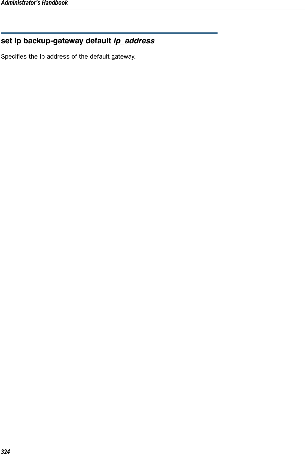
![325VDSL Settings☛ CAUTION!These settings are for very advanced users and lab technicians. Exercise extreme caution when modifying any of these settings.set vdsl sys-option [ 0x00 - 0xff ] sys-bandplan [ 0x00 - 0xff ] psd-mask-level [ 0x00 - 0xff ] pbo-k1_1 [ 0x00000000 - 0xffffffff ] pbo-k1_2 [ 0x00000000 - 0xffffffff ] pbo-k1_3 [ 0x00000000 - 0xffffffff ] pbo-k2_1 [ 0x00000000 - 0xffffffff ] pbo-k2_2 [ 0x00000000 - 0xffffffff ] pbo-k2_3 [ 0x00000000 - 0xffffffff ] line-type [ 0x00 - 0xff ] us-max-inter-delay [ 0x00 - 0xff ] ds-max-inter-delay [ 0x00 - 0xff ] us-target-noise-margin [ 0x0000 - 0xffff ] ds-target-noise-margin [ 0x0000 - 0xffff ] min-noise-margin [ 0x0000 - 0xffff ] port-bandplan [ 0x00 - xff ] framing-mode [ 0x00 - 0xff ] band-mod [ 0x00 - 0xff ] port-option [ 0x00 - 0xff ] power-mode [ 0x00 - 0xff ] tx-filter [ 0x00 - 0xff ] rx-filter [ 0x00 - 0xff ] dying-gasp [ off | on ]VDSL Parameter DefaultsParameter Default Meaningsys-option 0x00 VDSL system option(bit0=ntr, 1=margin, 2=ini, 3=pbo, 4=tlan, 5=pbo)sys-bandplan 0x02 VDSL system bandplan(bp_3_998_4=2, bp4_997_3=3, bp5_997_3=4…)psd-mask-level 0x00 VDSL system psd mask(def=0, 1=ansim1cab, 2=ansim2cab, 3=etsim1cab, 4=etsim2cab)pbo-k1_1 0x00 VDSL system power back-off k1_1pbo-k1_2 0x00 VDSL system power back-off k1_2pbo-k1_3 0x00 VDSL system power back-off k1_3pbo-k2_1 0x00 VDSL system power back-off k2_1pbo-k2_2 0x00 VDSL system power back-off k2_2](https://usermanual.wiki/ARRIS/224762/User-Guide-1097848-Page-325.png)
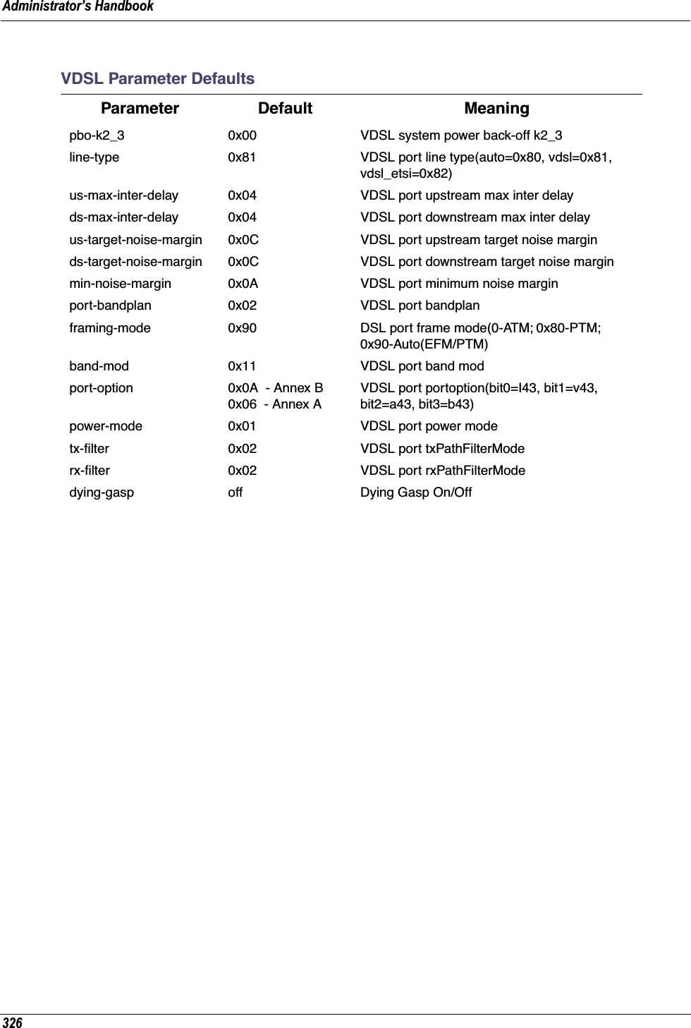
![327VDSL Parameters Accepted ValuesParameter Accepted Valuessys-option Bit[0]: NTR_DISABLEBit[1]: ALW_MARGIN_ADJUST.1: the SNR margin for the optional band is reduced by up to 2.5 dB, but never below a minimum of 4 dB.Bit[2]: SUPPORT_INI Bit[4]: TLAN EnableBit[5]: PBO Weak mode Enable (Applicable only when PBO Bit[3]=0.Bit[6]: ADSL_SAFE_MODE EnableBit[7]: TLAN_SAFE_MODE Enable (Applicable only when TLAN Enable Bit[4] is set. If TLAN_SAFE_MODE not set, line will attempt to retrain at higher rates, but less stable line)sys-bandplan BP1_998_3 (0x00)BP2_998_3 (0x01)BP998_3B_8_5M (0x01) BP3_998_4 (0x02)BP998_4B_12M (0x02)BP4_997_3 (0x03)BP997_3B_7_1M (0x03)BP5_997_3 (0x04)BP6_997_4 (0x05)BP997_4B_7_1M (0x05)BP7_MXU_3 (0x06)FLEX_3B_8_5M (0x06)BP8_MXU_2 (0x07)BP9_998_2 (0x08)BP10_998_2 (0x09)BP998_2B_3_8M (0x09)BP11_998_2 (0x0A)BP12_998_2 (0x0B)BP13_MXU_3 (0x0C)BP14_MXU_3 (0x0D)BP15_MXU_3 (0x0E)BP16_997_4B_4P (0x0F)BP17_998_138_4400 (0x10)BP18_997_138_4400(0x11)BP19_997_32_4400(0x12)BP20_998_138_4400_opBand (0x15)BP21_997_138_4400_opBand (0x16)BP22_998_138_4400_opBand(0x16)BP23_998_138_16000 (0x17)BP24_998_3B_8KHZ (0x18)BP25_998_138_17600 (0x19)BP26_CH1_3 (0x1A)BP27_CH1_4 (0x1B)](https://usermanual.wiki/ARRIS/224762/User-Guide-1097848-Page-327.png)
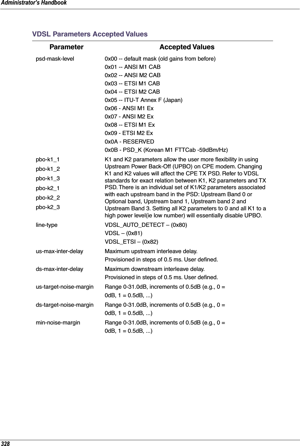
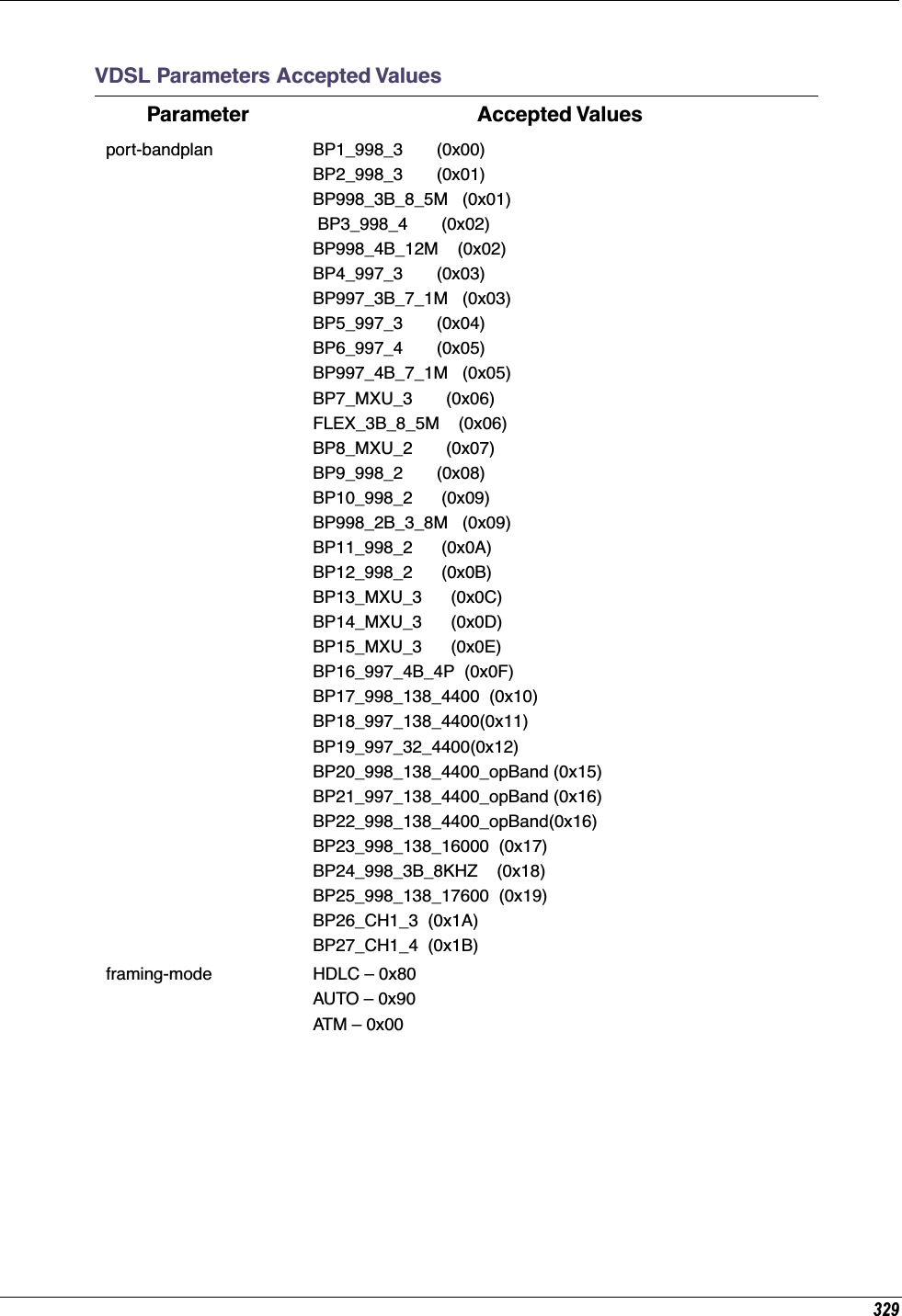
![Administrator’s Handbook330band-mod Bit 0, 1: Tx Cfg band1- All tones on2- All tones below 640 Khz are turned off3- All tones below 1.1 Mhz are turned offBit 2,3: Not usedBit 4,5: Rx Cfg band1- All tones on2- All tones below 640 Khz are turned off3- All tones below 1.1 Mhz are turned offBit 6, 7:Optional band0- No Optional band1- ANNEX_A_6_32 ( ie. 25KHz to 138 KHz)2- ANNEX_B_32_64 (ie. 138 KHz to 276 KHz)3- ANNEX_B_6_64 (ie. 25KHz to 276 KHz)port-option Bit [0]: I 43 G.hs carrier set.Bit [1]: V 43 G.hs carrier set.Bit [2]. A 43 G.hs carrier set.Bit [3]: B 43 G.hs carrier set.Bit[4:7]: shall be set to 0.power-mode 0: 8.5dBm power output1: 11.5 dBm power outputtx-filter 0: using internal filter in Tx path1: using K1 external filter in Tx path(for Korea VLR Application)2: using U1 external filter in Tx path(for US / Korea VLR Application)3: using H1 external filter in Tx path(for 100/100 Application)rx-filter 0: using internal filter in Rx path1: using K1 external filter in Rx path(for Korea VLR Application)2: using U1 external filter in Rx path(for US / Korea VLR Application)3: using H1 external filter in Rx path(for 100/100 Application)dying-gasp Dying Gasp is a message sent from CPE to CO using the indica-tor bit. It indicates that the CPE is experiencing an impending loss of power.Off: Dying Gasp off (don't send a message to CO).On: Dying Gasp on.VDSL Parameters Accepted ValuesParameter Accepted Values](https://usermanual.wiki/ARRIS/224762/User-Guide-1097848-Page-330.png)
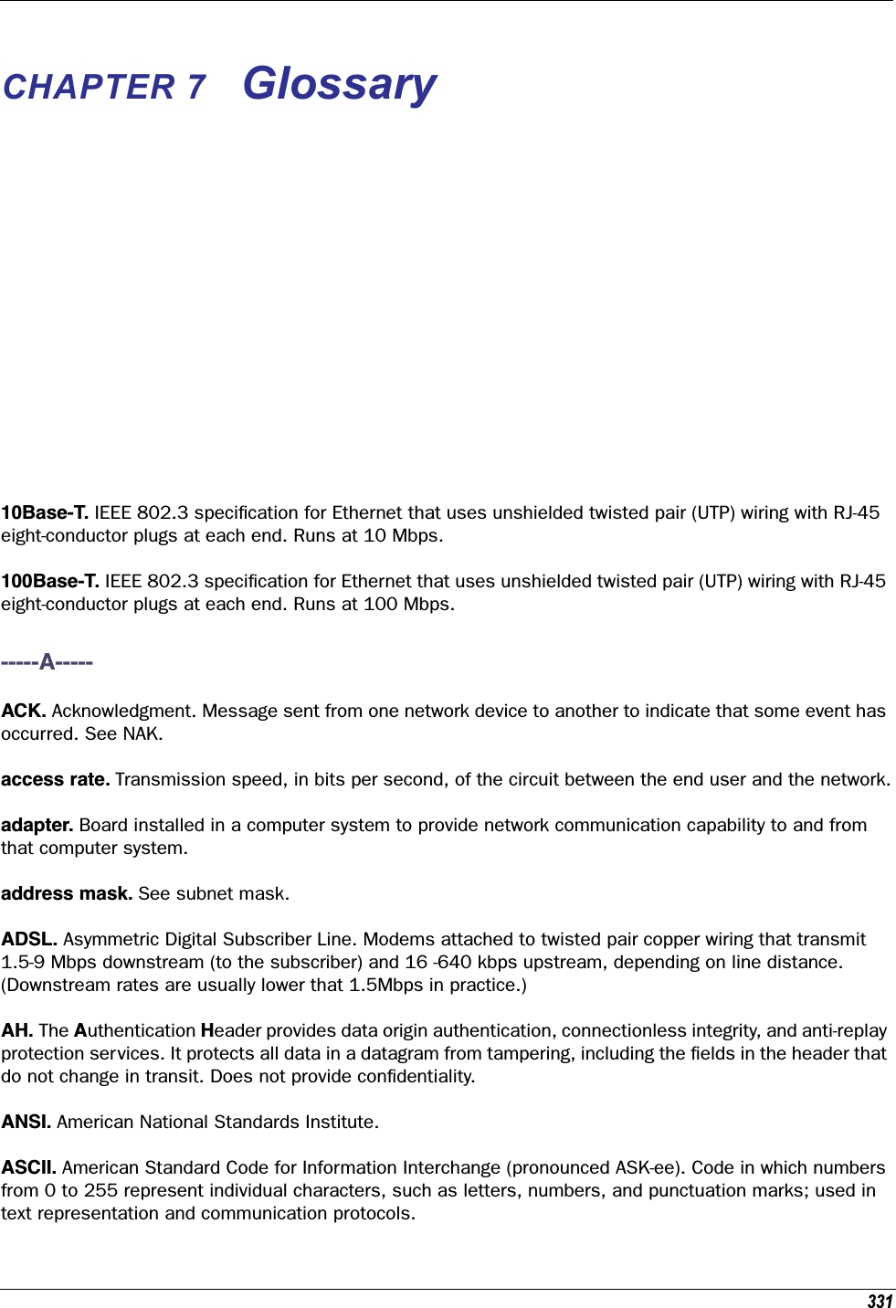
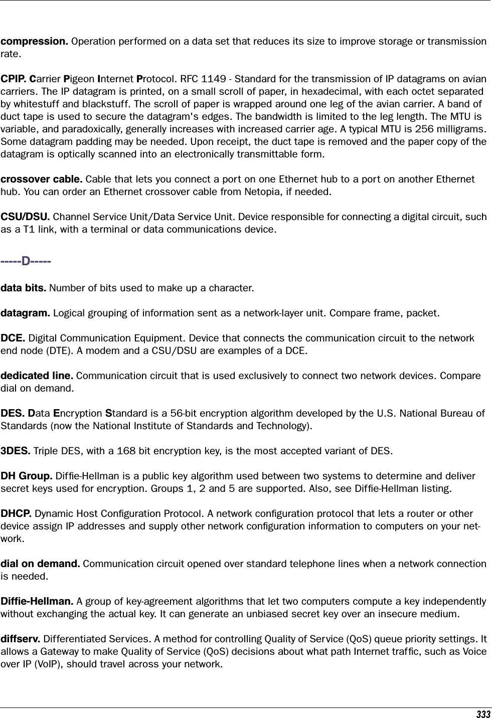
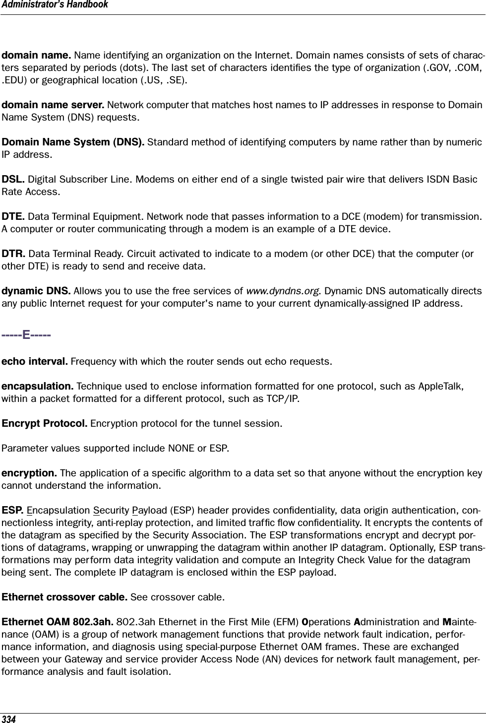
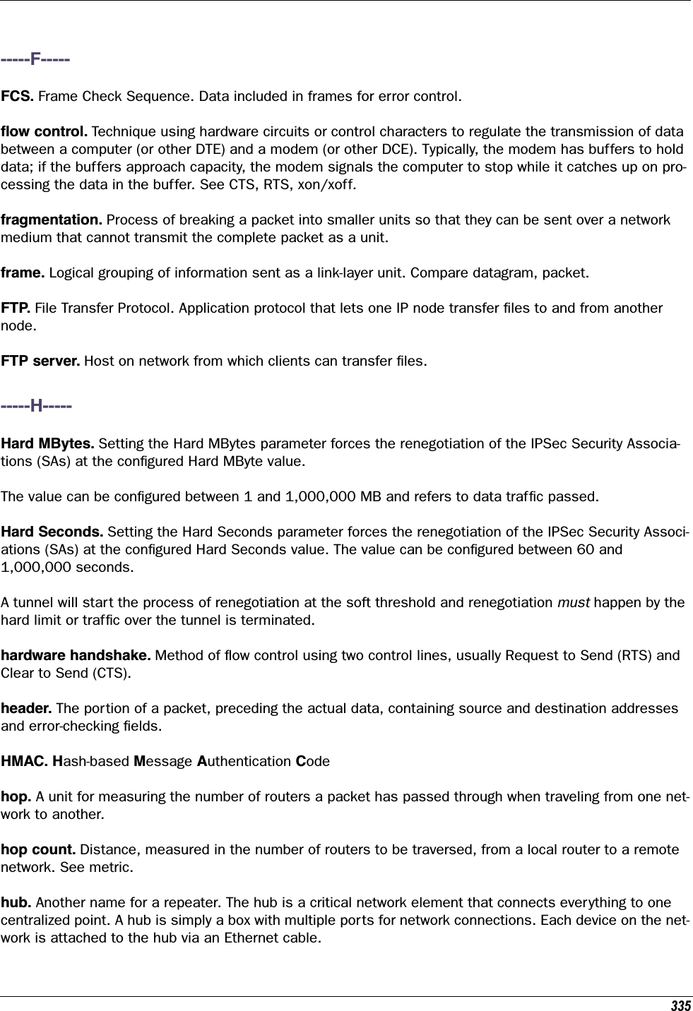

![34747 CFR Part 68 InformationFCC Requirements1. The Federal Communications Commission (FCC) has established Rules which permit this device to be directly connected to the telephone network. Standardized jacks are used for these connections. This equipment should not be used on party lines or coin phones.2. If this device is malfunctioning, it may also be causing harm to the telephone network; this device should be disconnected until the source of the problem can be determined and until repair has been made. If this is not done, the telephone company may temporarily disconnect service.3. The telephone company may make changes in its technical operations and procedures; if such changes affect the compatibility or use of this device, the telephone company is required to give adequate notice of the changes. You will be advised of your right to file a complaint with the FCC.4. If the telephone company requests information on what equipment is connected to their lines, inform them of:a. The telephone number to which this unit is connected.b. The ringer equivalence number. [0.XB]c. The USOC jack required. [RJ11C]d. The FCC Registration Number. [XXXUSA-XXXXX-XX-E]Items (b) and (d) are indicated on the label. The Ringer Equivalence Number (REN) is used to determine how many devices can be connected to your telephone line. In most areas, the sum of the REN's of all devices on any one line should not exceed five (5.0). If too many devices are attached, they may not ring properly.FCC Statementsa) This equipment complies with Part 68 of the FCC rules and the requirements adopted by the ACTA. On the bottom of this equipment is a label that contains, among other information, a product identifier in the format US:AAAEQ##TXXXX. If requested, this number must be provided to the telephone company.b) List all applicable certification jack Universal Service Order Codes (“USOC”) for the equipment: RJ11.c) A plug and jack used to connect this equipment to the premises wiring and telephone network must comply with the applicable FCC Part 68 rules and requirements adopted by the ACTA. A compliant telephone cord and modular plug is provided with this product. It is designed to be connected to a compatible modular jack that is also compliant. See installation instructions for details.d) The REN is used to determine the number of devices that may be connected to a telephone line. Excessive RENs on a telephone line may result in the devices not ringing in response to an incoming call. In most but not all areas, the sum of RENs should not exceed five (5.0). To be certain of the number of devices that may be connected to a line, as determined by the total RENs, contact the local telephone company. For products approved after July 23, 2002, the REN for this product is part of the product identifier that has the format US:AAAEQ##TXXXX. The digits represented by ## are the REN without a decimal point (e.g., 03 is a REN of 0.3). For earlier products, the REN is separately shown on the label.e) If this equipment, the Motorola Netopia® 2200-, 3300- or 7000-series router, causes harm to the telephone network, the telephone company will notify you in advance that temporary discontinuance of service may be required. But if advance notice isn’t practical, the telephone company will notify the customer as soon as possible. Also, you will be advised of your right to file a complaint with the FCC if you believe it is necessary.f) The telephone company may make changes in its facilities, equipment, operations or procedures that could affect the operation of the equipment. If this happens the telephone company will provide advance notice in order for you to make necessary modifications to maintain uninterrupted service.g) If trouble is experienced with this equipment, the Motorola Netopia® 2200-, 3300- or 7000-series router, for repair or warranty information, please contact:Motorola Technical Support510-597-5400www.netopia.com.If the equipment is causing harm to the telephone network, the telephone company may request that you disconnect the equipment until the problem is resolved.](https://usermanual.wiki/ARRIS/224762/User-Guide-1097848-Page-347.png)
![349Original SSLeay License/Copyright (C) 1995-1998 Eric Young (eay@cryptsoft.com) All rights reserved.This package is an SSL implementation written by Eric Young (eay@cryptsoft.com). The implementation was written so as to conform with Netscape’s SSL.This library is free for commercial and non-commercial use as long as the following conditions are adhered to. The following conditions apply to all code found in this distribution, be it the RC4, RSA, lhash, DES, etc., code; not just the SSL code. The SSL documentation included with this distribution is covered by the same copyright terms except that the holder is Tim Hudson (tjh@cryptsoft.com).Copyright remains Eric Young's, and as such any Copyright notices in the code are not to be removed. If this pack-age is used in a product, Eric Young should be given attribution as the author of the parts of the library used. This can be in the form of a textual message at program startup or in documentation (online or textual) provided with the package.Redistribution and use in source and binary forms, with or without modification, are permitted provided that the fol-lowing conditions are met: 1. Redistributions of source code must retain the copyright notice, this list of conditions and the following dis-claimer. 2. Redistributions in binary form must reproduce the above copyright notice, this list of conditions and the following disclaimer in the documentation and/or other materials provided with the distribution. 3. All advertising materials mentioning features or use of this software must display the following acknowledge-ment: “This product includes cryptographic software written by Eric Young (eay@cryptsoft.com)” The word 'cryptographic' can be left out if the routines from the librar y being used are not cryptographic related :-). 4. If you include any Windows specific code (or a derivative thereof) from the apps directory (application code) you must include an acknowledgement: “This product includes software written by Tim Hudson (tjh@cryptsoft.com)”THIS SOFTWARE IS PROVIDED BY ERIC YOUNG ``AS IS'' AND ANY EXPRESS OR IMPLIED WARRANTIES, INCLUDING, BUT NOT LIMITED TO, THE IMPLIED WARRANTIES OF MERCHANTABILITY AND FITNESS FOR A PARTICULAR PURPOSE ARE DISCLAIMED. IN NO EVENT SHALL THE AUTHOR OR CONTRIBUTORS BE LIABLE FOR ANY DIRECT, INDIRECT, INCIDENTAL, SPECIAL, EXEMPLARY, OR CONSEQUENTIAL DAMAGES (INCLUDING, BUT NOT LIMITED TO, PROCURE-MENT OF SUBSTITUTE GOODS OR SERVICES; LOSS OF USE, DATA, OR PROFITS; OR BUSINESS INTERRUPTION) HOWEVER CAUSED AND ON ANY THEORY OF LIABILITY, WHETHER IN CONTRACT, STRICT LIABILITY, OR TORT (INCLUDING NEGLIGENCE OR OTHERWISE) ARISING IN ANY WAY OUT OF THE USE OF THIS SOFTWARE, EVEN IF ADVISED OF THE POSSIBILITY OF SUCH DAMAGE.The licence and distribution terms for any publicly available version or derivative of this code cannot be changed. i.e. this code cannot simply be copied and put under another distribution licence [including the GNU Public Licence.]Portions of this software are based in part on the work of the following:Copyright (C) 1995, 1996, 1997, and 1998 WIDE Project. All rights reserved.Redistribution and use in source and binary forms, with or without modification, are permitted provided that the fol-lowing conditions are met: 1. Redistributions of source code must retain the above copyright notice, this list of conditions and the following disclaimer. 2. Redistributions in binary form must reproduce the above copyright notice, this list of conditions and the following disclaimer in the documentation and/or other materials provided with the distribution. 3. Neither the name of the project nor the names of its contributors may be used to endorse or promote products derived from this software without specific prior written permission.THIS SOFTWARE IS PROVIDED BY THE PROJECT AND CONTRIBUTORS ``AS IS'' AND ANY EXPRESS OR IMPLIED WARRANTIES, INCLUDING, BUT NOT LIMITED TO, THE IMPLIED WARRANTIES OF MERCHANTABILITY AND FITNESS FOR A PARTICULAR PURPOSE ARE DISCLAIMED. IN NO EVENT SHALL THE PROJECT OR CONTRIBUTORS BE LIABLE FOR ANY DIRECT, INDIRECT, INCIDENTAL, SPECIAL, EXEMPLARY, OR CONSEQUENTIAL DAMAGES (INCLUDING, BUT NOT LIMITED TO, PROCUREMENT OF SUBSTITUTE GOODS OR SERVICES; LOSS OF USE, DATA, OR PROFITS; OR BUSINESS INTERRUPTION) HOWEVER CAUSED AND ON ANY THEORY OF LIABILITY, WHETHER IN CONTRACT, STRICT](https://usermanual.wiki/ARRIS/224762/User-Guide-1097848-Page-349.png)