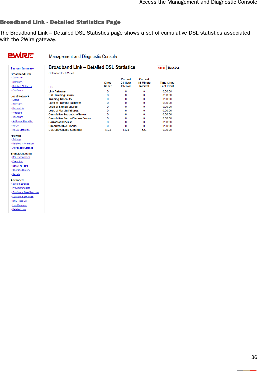
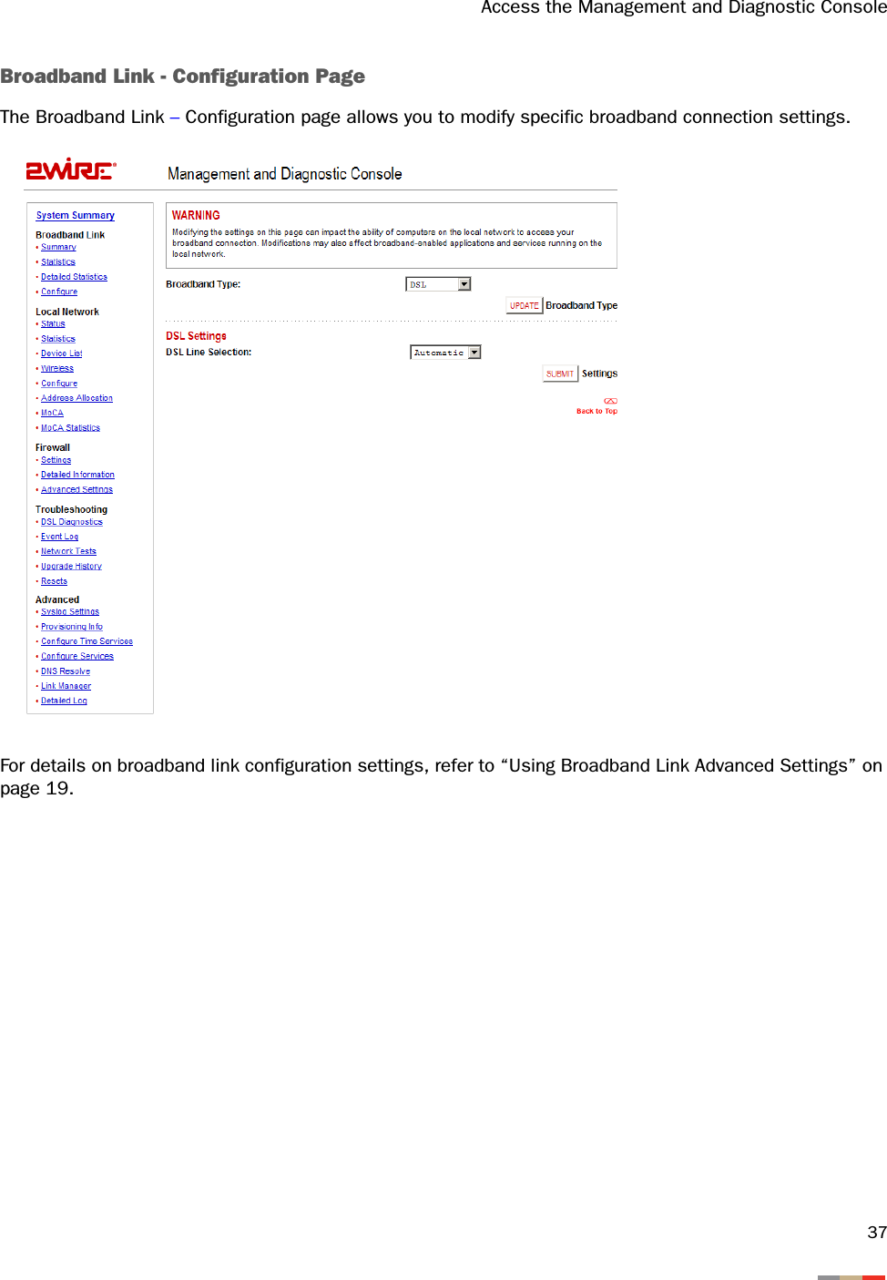
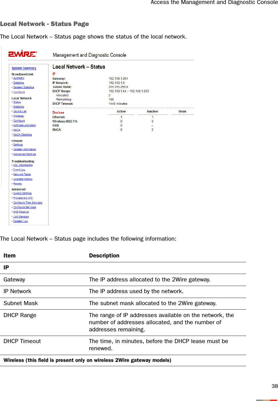
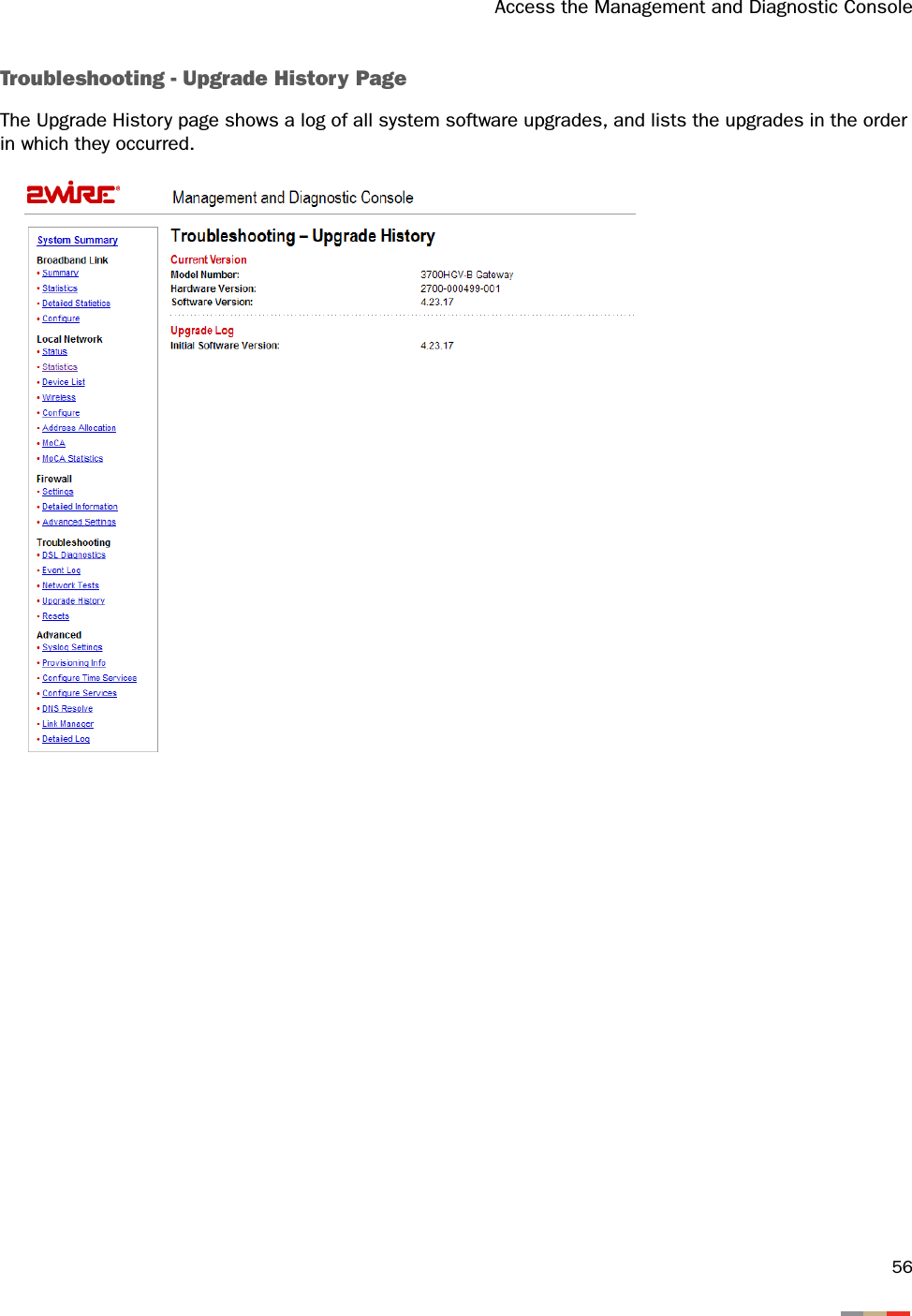
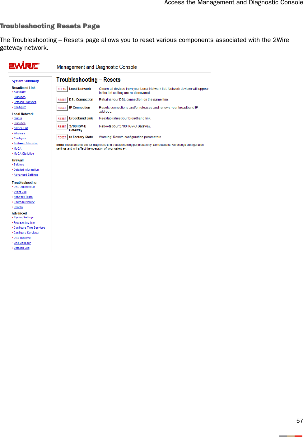
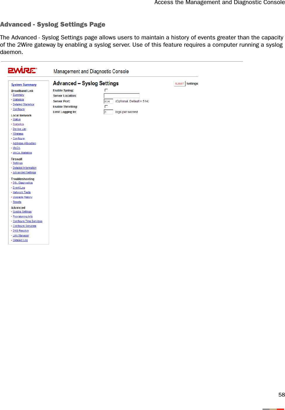
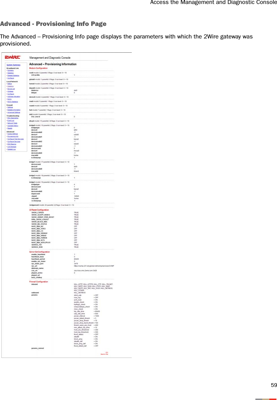
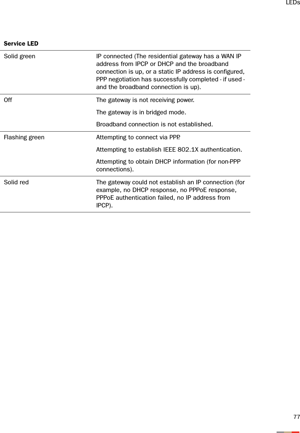
ARRIS 2W3800HP 2Wire Gateway User Manual Gateway IG 3700

Pace Americas 2Wire Gateway Gateway IG 3700

Users Manual

iContentsContents i3800HGV-B Overview  . . . . . . . . . . . . . . . . . . . . . . . . . . . . . . . . . . . . . . . . . . . . . . . . . . . . . . . . . . . . 1Installation Requirements  . . . . . . . . . . . . . . . . . . . . . . . . . . . . . . . . . . . . . . . . . . . . . . . . . . . . . . . . . 4Connect the Computer to the Gateway  . . . . . . . . . . . . . . . . . . . . . . . . . . . . . . . . . . . . . . . . . . . . . . . 5Choose a Computer and Connection Type  . . . . . . . . . . . . . . . . . . . . . . . . . . . . . . . . . . . . . . . . . . . . . .5Ethernet Connection  . . . . . . . . . . . . . . . . . . . . . . . . . . . . . . . . . . . . . . . . . . . . . . . . . . . . . . . . . . . . . 6Wireless Connection  . . . . . . . . . . . . . . . . . . . . . . . . . . . . . . . . . . . . . . . . . . . . . . . . . . . . . . . . . . . . . 7Non-2Wire Wireless Adapter Configuration . . . . . . . . . . . . . . . . . . . . . . . . . . . . . . . . . . . . . . . . 8Locating the Serial Number and Wireless Encryption Key  . . . . . . . . . . . . . . . . . . . . . . . . . . 8Configuring the Adapter  . . . . . . . . . . . . . . . . . . . . . . . . . . . . . . . . . . . . . . . . . . . . . . . . . . 8USB to PC Connection  . . . . . . . . . . . . . . . . . . . . . . . . . . . . . . . . . . . . . . . . . . . . . . . . . . . . . . . . . . . . 9Install the 2Wire Gateway USB Driver - Windows   . . . . . . . . . . . . . . . . . . . . . . . . . . . . . . . . . . . 9Install the 2Wire Gateway USB Driver - Macintosh  . . . . . . . . . . . . . . . . . . . . . . . . . . . . . . . . . 10Connect the Broadband Interface  . . . . . . . . . . . . . . . . . . . . . . . . . . . . . . . . . . . . . . . . . . . . . . . . . . 11Connecting to VDSL via CoAX  . . . . . . . . . . . . . . . . . . . . . . . . . . . . . . . . . . . . . . . . . . . . . . . . . . . . . . 11Connect to IPTV  . . . . . . . . . . . . . . . . . . . . . . . . . . . . . . . . . . . . . . . . . . . . . . . . . . . . . . . . . . . . . . . 12Setting Up IPTV  . . . . . . . . . . . . . . . . . . . . . . . . . . . . . . . . . . . . . . . . . . . . . . . . . . . . . . . . . . . . . . . . 12Gateway User Interface   . . . . . . . . . . . . . . . . . . . . . . . . . . . . . . . . . . . . . . . . . . . . . . . . . . . . . . . . . 13Gateway (System) Pages  . . . . . . . . . . . . . . . . . . . . . . . . . . . . . . . . . . . . . . . . . . . . . . . . . . . . . . . . . 13Viewing Your System Summary . . . . . . . . . . . . . . . . . . . . . . . . . . . . . . . . . . . . . . . . . . . . . . . 13Setting a System Password  . . . . . . . . . . . . . . . . . . . . . . . . . . . . . . . . . . . . . . . . . . . . . . . . . 14Changing Your Time Zone Settings  . . . . . . . . . . . . . . . . . . . . . . . . . . . . . . . . . . . . . . . . . . . . 14Viewing System Details  . . . . . . . . . . . . . . . . . . . . . . . . . . . . . . . . . . . . . . . . . . . . . . . . . . . . 15Broadband Link Pages  . . . . . . . . . . . . . . . . . . . . . . . . . . . . . . . . . . . . . . . . . . . . . . . . . . . . . . . . . . . 15Viewing Your Broadband Link Summary . . . . . . . . . . . . . . . . . . . . . . . . . . . . . . . . . . . . . . . . . 15Viewing Broadband Link Details  . . . . . . . . . . . . . . . . . . . . . . . . . . . . . . . . . . . . . . . . . . . . . . 16Using Broadband Diagnostics . . . . . . . . . . . . . . . . . . . . . . . . . . . . . . . . . . . . . . . . . . . . . . . . 17Viewing Statistics  . . . . . . . . . . . . . . . . . . . . . . . . . . . . . . . . . . . . . . . . . . . . . . . . . . . . . . . . 18Using Broadband Link Advanced Settings  . . . . . . . . . . . . . . . . . . . . . . . . . . . . . . . . . . . . . . . 19Home Network Pages   . . . . . . . . . . . . . . . . . . . . . . . . . . . . . . . . . . . . . . . . . . . . . . . . . . . . . . . . . . . 20Viewing Your Home Network Summary   . . . . . . . . . . . . . . . . . . . . . . . . . . . . . . . . . . . . . . . . . 20Local Devices  . . . . . . . . . . . . . . . . . . . . . . . . . . . . . . . . . . . . . . . . . . . . . . . . . . . . . . . . 20Status at a Glance Panel  . . . . . . . . . . . . . . . . . . . . . . . . . . . . . . . . . . . . . . . . . . . . . . . . 21Monitoring Your Wireless Settings   . . . . . . . . . . . . . . . . . . . . . . . . . . . . . . . . . . . . . . . . . . . . 21Customizing Security Settings   . . . . . . . . . . . . . . . . . . . . . . . . . . . . . . . . . . . . . . . . . . . . 23Configuring Additional Settings . . . . . . . . . . . . . . . . . . . . . . . . . . . . . . . . . . . . . . . . . . . . . . . 23Configuring Advanced Settings  . . . . . . . . . . . . . . . . . . . . . . . . . . . . . . . . . . . . . . . . . . . . . . . 24Editing Address Allocation Settings . . . . . . . . . . . . . . . . . . . . . . . . . . . . . . . . . . . . . . . . . 25Firewall Pages . . . . . . . . . . . . . . . . . . . . . . . . . . . . . . . . . . . . . . . . . . . . . . . . . . . . . . . . . . . . . . . . . 26Viewing Your Firewall Summary . . . . . . . . . . . . . . . . . . . . . . . . . . . . . . . . . . . . . . . . . . . . . . . 26Configuring Firewall Settings   . . . . . . . . . . . . . . . . . . . . . . . . . . . . . . . . . . . . . . . . . . . . . . . . 28Configuring Advanced Firewall Settings  . . . . . . . . . . . . . . . . . . . . . . . . . . . . . . . . . . . . . . . . . 29Enabling Advanced Security  . . . . . . . . . . . . . . . . . . . . . . . . . . . . . . . . . . . . . . . . . . . . . . 29Allowing Inbound and Outbound Traffic  . . . . . . . . . . . . . . . . . . . . . . . . . . . . . . . . . . . . . . 30Disabling Attack Detection  . . . . . . . . . . . . . . . . . . . . . . . . . . . . . . . . . . . . . . . . . . . . . . . 30Access the Management and Diagnostic Console  . . . . . . . . . . . . . . . . . . . . . . . . . . . . . . . . . . . . . . 32
ContentsiiAccessing the Management and Diagnostic Console  . . . . . . . . . . . . . . . . . . . . . . . . . . . . . . . . . . . . . 32System Summary Page   . . . . . . . . . . . . . . . . . . . . . . . . . . . . . . . . . . . . . . . . . . . . . . . . . . . . 32Broadband Link - Summary Page   . . . . . . . . . . . . . . . . . . . . . . . . . . . . . . . . . . . . . . . . . . . . . 34Broadband Link - Statistics Page   . . . . . . . . . . . . . . . . . . . . . . . . . . . . . . . . . . . . . . . . . . . . . 35Broadband Link - Configuration Page . . . . . . . . . . . . . . . . . . . . . . . . . . . . . . . . . . . . . . . . . . . 37Local Network - Status Page . . . . . . . . . . . . . . . . . . . . . . . . . . . . . . . . . . . . . . . . . . . . . . . . . 38Local Network - Statistics Page   . . . . . . . . . . . . . . . . . . . . . . . . . . . . . . . . . . . . . . . . . . . . . . 40Local Network - Device List Page   . . . . . . . . . . . . . . . . . . . . . . . . . . . . . . . . . . . . . . . . . . . . . 41Local Network - Wireless Settings Page . . . . . . . . . . . . . . . . . . . . . . . . . . . . . . . . . . . . . . . . . 42Local Network - Configuration Page . . . . . . . . . . . . . . . . . . . . . . . . . . . . . . . . . . . . . . . . . . . . 43Enabling Router Behind Router Alert  . . . . . . . . . . . . . . . . . . . . . . . . . . . . . . . . . . . . . . . . . . . 43Local Network - Address Allocation Page  . . . . . . . . . . . . . . . . . . . . . . . . . . . . . . . . . . . . . . . . 44Local Network - Configure the MoCA Network Page   . . . . . . . . . . . . . . . . . . . . . . . . . . . . . . . . 45Local Network - MoCA Statistics Page  . . . . . . . . . . . . . . . . . . . . . . . . . . . . . . . . . . . . . . . . . . 46Firewall - Settings Page  . . . . . . . . . . . . . . . . . . . . . . . . . . . . . . . . . . . . . . . . . . . . . . . . . . . .47Firewall - Detailed Information Page   . . . . . . . . . . . . . . . . . . . . . . . . . . . . . . . . . . . . . . . . . . . 48Firewall - Advanced Settings Page . . . . . . . . . . . . . . . . . . . . . . . . . . . . . . . . . . . . . . . . . . . . . 49Troubleshooting - DSL Diagnostics Page  . . . . . . . . . . . . . . . . . . . . . . . . . . . . . . . . . . . . . . . . 50Analyzing General Information   . . . . . . . . . . . . . . . . . . . . . . . . . . . . . . . . . . . . . . . . . . . . 50Reviewing Training History  . . . . . . . . . . . . . . . . . . . . . . . . . . . . . . . . . . . . . . . . . . . . . . . 51Reviewing Bitloading  . . . . . . . . . . . . . . . . . . . . . . . . . . . . . . . . . . . . . . . . . . . . . . . . . . . 52Troubleshooting - Event Log Page  . . . . . . . . . . . . . . . . . . . . . . . . . . . . . . . . . . . . . . . . . . . . . 53Troubleshooting - Network Tests Page . . . . . . . . . . . . . . . . . . . . . . . . . . . . . . . . . . . . . . . . . . 55Troubleshooting - Upgrade History Page   . . . . . . . . . . . . . . . . . . . . . . . . . . . . . . . . . . . . . . . . 56Troubleshooting Resets Page  . . . . . . . . . . . . . . . . . . . . . . . . . . . . . . . . . . . . . . . . . . . . . . . . 57Advanced - Syslog Settings Page   . . . . . . . . . . . . . . . . . . . . . . . . . . . . . . . . . . . . . . . . . . . . . 58Advanced - Provisioning Info Page . . . . . . . . . . . . . . . . . . . . . . . . . . . . . . . . . . . . . . . . . . . . . 59Advanced - Configure Time Services Page  . . . . . . . . . . . . . . . . . . . . . . . . . . . . . . . . . . . . . . . 60Advanced - Configure Services Page  . . . . . . . . . . . . . . . . . . . . . . . . . . . . . . . . . . . . . . . . . . . 61Advanced - DNS Resolve Page  . . . . . . . . . . . . . . . . . . . . . . . . . . . . . . . . . . . . . . . . . . . . . . . 62Advanced - Link Manager States Page . . . . . . . . . . . . . . . . . . . . . . . . . . . . . . . . . . . . . . . . . . 63Advanced - Detailed Log Page   . . . . . . . . . . . . . . . . . . . . . . . . . . . . . . . . . . . . . . . . . . . . . . . 64Upgrade the Software  . . . . . . . . . . . . . . . . . . . . . . . . . . . . . . . . . . . . . . . . . . . . . . . . . . . . . . . . . . . 65Configuring Multiple Static IP Addresses . . . . . . . . . . . . . . . . . . . . . . . . . . . . . . . . . . . . . . . . . . . . . 67Step 1: Enable Public Network Mode   . . . . . . . . . . . . . . . . . . . . . . . . . . . . . . . . . . . . . . . . . . . . . . . . 68Step 2: Allocate Public IP Addresses to the LAN Clients  . . . . . . . . . . . . . . . . . . . . . . . . . . . . . . . . . . . 69Step 3: Configure Firewall Rules . . . . . . . . . . . . . . . . . . . . . . . . . . . . . . . . . . . . . . . . . . . . . . . . . . . . 70Sample Configuration   . . . . . . . . . . . . . . . . . . . . . . . . . . . . . . . . . . . . . . . . . . . . . . . . . . . . . . . . . . . 71LEDs   . . . . . . . . . . . . . . . . . . . . . . . . . . . . . . . . . . . . . . . . . . . . . . . . . . . . . . . . . . . . . . . . . . . . . . . 76LED overview   . . . . . . . . . . . . . . . . . . . . . . . . . . . . . . . . . . . . . . . . . . . . . . . . . . . . . . . . . . . . . . . . . 76Glossary . . . . . . . . . . . . . . . . . . . . . . . . . . . . . . . . . . . . . . . . . . . . . . . . . . . . . . . . . . . . . . . . . . . . . 78Regulatory Information  . . . . . . . . . . . . . . . . . . . . . . . . . . . . . . . . . . . . . . . . . . . . . . . . . . . . . . . . . . 79
13800HGV-B OverviewThe 3800HGV-B is a residential gateway used to connect to the Lightspeed network. It has many of the features of an advanced broadband router as well as some additional features. Following are some of the major features of the 2Wire gateway.Advanced modem technology. 2Wire’s modem technology features enhanced bridge tap, long loop, and disturber performance.Super-fast router. The 2Wire gateway’s router provides the fastest data transfer speeds available between the network and the Internet. The high-performance router distributes data seamlessly to all of the computers on the network, without a dramatic loss of performance or speed.Professional-grade firewall. The 2Wire gateway firewall includes both standard NAT/PAT security and Stateful Packet Inspection to defend against Denial of Service Internet attacks.Flexible networking. The 2Wire gateway includes a variety of home networking technologies in one box: Ethernet, direct USB, HyperG wireless,1 and MoCA.Figure 1. 3800HGV-B, Rear ViewNote: The Phones Lines 1&2/Aux Line ports are reserved for connecting to VoIP service, and are not currently active.Ethernet. Ethernet is a local area network (LAN) technology that transmits information between computers at speeds of 10 or 100 Mbps. The 3700HGV-B has 4 Ethernet ports for directly connecting computers or devices. If the home or office is wired for Ethernet, use the Ethernet interface(s) on the gateway to create a broadband network.USB. The 2Wire gateway’s USB 1.1 port allows users to directly connect a computer or other network-ready device.1. Some interfaces are not available on specific models.
Networking Technology Overview2Wireless. The 2Wire gateway includes an integrated wireless access point, which allows users to roam wirelessly throughout the home or office. 2Wire's high-powered wireless technology virtually eliminates wireless “coldspots” in the home. The 2Wire gateway’s high power 400mW transmitter ensures that users benefit from increased wireless bandwidth throughout the coverage area. In addition, the 2Wire gateway employs a special triple antenna design. The third antenna is used only for transmitting packets, thus mitigating the power loss associated with switching the antenna use back and forth between transmit and receive. This results in greater access point sensitivity, as antenna placement can be better optimized with a dedicated set of receive-only antennas.MoCA. MoCA technology allows users to easily share digital entertainment throughout the home using the existing coax cable infrastructure to distribute content such as video (SDTV and HDTV), music, games, and images. MoCA provides the following benefits:• Multi-room HDTV DVR. Allows users to record and share digital videos simultaneously in every room.• Multi-room gaming. Allows users to access games from various locations in the home and play simultaneously.• PC to TV. Allows users to merge data and video-centric networks throughout the home.802.1X Authentication. 802.1X Authentication provides port-based authentication using certificates. These certificates reside in the RADIUS authentication server and the 3700HGV-B gateway, and are signed by a Certificate Authority (CA). When the RADIUS server and the gateway successfully exchange certificates, access to the network is allowed.Prior to authentication, only limited security traffic (Layer 1 and Layer 2) is allowed on ports. After authentication, ports open up for all other traffic (such as DHCP, IP, or Layer 3 and above).The VDSL DSLAM is the authenticator between the 3700HGV-B and the RADIUS server. The RADIUS server provides authentication and authorization for the 3700HGV-B, and decides if the VDSLAM will open the port for upper layer traffic. The 3700HGV-B and RADIUS server will exchange certificates to provide mutual authentication. They will ensure that the certificate was issued from a trusted CA and that the certificates are valid, and other related information.If the VDSL DSLAM port is not configured for 802.1X, the 3700HGV-B attempts to authenticate 3 times. If it cannot authenticate, it bypasses 802.1X authentication. This does not mean that the 3700HGV-B will be allowed on the network, just that it does not attempt the authentication again until power cycled or the network requests it.802.1x SetupRADIUSVDSL DSLAM(Authenticator)VDSL HomePortal(Supplicant) RADIUS Server(AuthenticationServer)EAP/TLS EAP to Radius
Networking Technology Overview3VDSL. VDSL (very high bit-rate DSL) operates over the copper wires in a phone line in a manner similar to ADSL, but at much faster speeds. VDSL can achieve speeds as high as 52 Mbps downstream and 16 Mbps upstream, as opposed to ADSL (up to 8 Mbps downstream and 800 Kbps upstream).
4Installation RequirementsBefore you begin installation, review the 3800HGV-B package contents and ensure that you have available the items shown in Figure 21.Figure 2. 2Wire and Service Provider Installation ComponentsNote: Vertical orientation is the preferred method for mounting the 3700HGV-B gateway. Please use the mounting stand included with the 3700HGV-B gateway.1. Additional components may be provided by your service provider.
5Connect the Computer to the GatewayNote: Any equipment or devices that must be installed at the NID are outside the scope of this document.Choose a Computer and Connection TypeIf the customer has ordered IPTV and High Speed Internet, the preferred location for installing the 3700HGV-B is by the first video set top box. In this case, the first PC may or may not be located in the same room. If the customer ordered High Speed Internet access only, then the 3700HGV-B should be installed near the first PC. Computers can be connected to the 3700HGV-B via Ethernet, wireless, USB, or MoCA.The first computer you connect to the network is used to configure the 3700HGV-B for proper operation. If the customer has not ordered High Speed Internet, then the technician must use their assigned laptop to configure the 3700HGV-B.Choose one of the following methods to connect the first computer to the 3700HGV-B. Save and close all open programs before you begin connecting the 3700HGV-B.Connection Type PageEthernet page 6Wireless page 7USB page 9
Connect the Computer to the Gateway6Ethernet Connection1. Connect the provided power adapter from the 3700HGV-B's POWER port to an electrical outlet. After the 3700HGV-B has completed its start up process, the POWER light on the front of the 3700HGV-B should be green.2. Connect the yellow Ethernet cable provided with the 3700HGV-B from any available ETHENET port on the 3700HGV-B to the computer’s Ethernet port.3. If the VDSL signal is carried over the phone line, connect the provided gray phone cable from the gateway's PHONE LINE port to telephone wall jack. If the VDSL signal is carried over coax, refer to page 11.
Connect the Computer to the Gateway7Wireless ConnectionRequires wireless-enabled notebook or a computer with an 802.11b/g wireless network adapter installed. Wireless adapters can be purchased from the service provider.1. Connect the provided AC power adapter from the 3700HGV-B’s POWER port to an electrical outlet. After the 3700HGV-B has completed its start up process, the POWER light on the front of the 3700HGV-B should be green.2. If the VDSL signal is carried over the phone line, connect the provided gray phone cable from the 3700HGV-B's PHONE LINE port to telephone wall jack. If the VDSL signal is carried over coax, refer to page 11.3. Install the wireless adapter according to the manufacturer’s instructions (see note below).Note: If you use a 2Wire wireless adapter (PCI, PC card, or USB adapter) for wireless networking, the 2Wire gateway Setup Wizard CD automatically configures it to communicate with the gateway during setup. If you are NOT using a 2Wire wireless adapter, you must manually configure your adapter to communicate with the gateway using the information on page 8.
Connect the Computer to the Gateway8Non-2Wire Wireless Adapter ConfigurationLocating the Serial Number and Wireless Encryption KeyA portion of the serial number of your 3700HGV-B is used as the network name (SSID). Beneath the serial number is a ten-digit number which is used as the encryption key. These are located on the bottom of your 3700HGV-B (shown in vertical orientation). You will need this information to configure your wireless adapter.Configuring the Adapter1. Install and configure your wireless adapter according to the manufacturer’s instructions.2. Use the network adapter configuration software or Windows network connection wizard to set the network name (SSID) and encryption key (WPA).a.The network name is the word “2WIRE” (in all capital letters), followed by the last three digits of the gateway serial number (for example, 2WIRE110).b. The encryption key is a 64-bit hex value, located beneath the bar code on the bottom of the 2Wire gateway. In the example, it is 4119627022.c. For Mac OS X users, you may need to enter the “$” character at the beginning of the encryption key (for example, $4119627022).Note: The above instructions are for users configuring their adapter with WPA. If the user’s wireless adapter doesn't support WPA they should use WEP; however, this decreases the level of security provided for wireless traffic.
Connect the Computer to the Gateway9USB to PC Connection1. Connect the provided AC power adapter from the 3700HGV-B’s POWER port to an electrical outlet. After the 3700HGV-B has completed its start up process, the POWER light on the front of the 3700HGV-B should be green.2. Connect the provided blue USB cable from the 3700HGV-B’s USB-PC port to the USB port on the computer.3. If the VDSL signal is carried over the phone line, connect the provided gray phone cable from the 3700HGV-B's PHONE LINE port to telephone wall jack. If the VDSL signal is carried over coax, refer to page 11.Install the 2Wire Gateway USB Driver - Windows1. Insert the 2Wire setup CD in your computer’s CD-ROM drive.2. Power on the computer. If the Add Hardware Wizard displays, follow the on-screen instructions. If prompted to identify where to search for drivers, deselect Floppy Disk drive and check CD-ROM drive.3. After the driver installs click Finish to complete the driver installation. The Setup Wizard will resume when the PC has rebooted.Note: Microsoft Windows 98 users may be prompted to insert the Windows 98 installation CD-ROM after installing the 2Wire gateway USB drivers. After the Windows 98 updates are complete, remove the Windows 98 CD and reinsert the Setup Wizard CD into the CD-ROM prior to rebooting the PC.
Connect the Computer to the Gateway10Install the 2Wire Gateway USB Driver - Macintosh Note: The 2Wire gateway supports USB for Macintosh OS 8.6, 9.2, 10.1.4, 10.1.5, 10.2.0, 10.2.1 to 10.2.6, 10.3.3 to 10.3.9, 10.4.0, and 10.4.1.Before making the USB connection to the gateway, you must install the 2Wire gateway USB driver on the computer. The following instructions are for USB installation on Macintosh computers running OS 10.2.1. With the computer powered on and the 2Wire Setup Wizard CD in the CD-ROM drive, double-click the 2Wire CD icon on the desktop.2. Double-click 2Wire USB to begin the driver installation.3. If the user has set up an administrator name and password, the Authenticate screen opens. Enter the administrator name and password and click OK.4. Follow the on-screen instructions. When the driver installation is complete, you will be prompted to restart the computer.5. After the computer restarts, connect the provided blue USB cable from the USB-PC port on the 2Wire gateway to the computer's USB port.
11Connect the Broadband InterfaceNow that you have completed the Power and LAN connections, it is time to connect to the broadband interface. There are two connection methods available:•VDSL over RJ-11• VDSL over CoaxIf the 3700HGV-B is receiving the VSDL signal via RJ-11, that step was completed in the previous chapter. If the 3700HGV-B is receiving the VSDL signal via CoAX, refer to the following section.Connecting to VDSL via CoAXFigure 3. Inside Wiring DiagramNID Line 1 (TDM)from NIDRGSTBSTBVDSL Splitter/BalunLANCar-5CAT-3CoaxVDSL CoaxPC LAN EthernetPC Wi-FiSplitter DiplexerMain SplitterLegendNID Line 1 (TDM)from NIDRGSTBSTBVDSL Splitter/BalunLANCar-5CAT-3CoaxVDSL CoaxPC LAN EthernetPC Wi-FiSplitter DiplexerMain SplitterLegend
12Connect to IPTVSetting Up IPTVWhile the 3700HGV-B supports MoCA directly connected to it, it will not be used by SBC during the Controlled Launch. Instead MoCA or HomePNA will be terminated on an Ethernet over CoAX bridge (for example, a Scientific Atlanta device or a Motorola NIM 100), which connects to an Ethernet port on the 3700HGV-B.Note: The NIM100 is independently powered, and should be installed close to a power outlet. Refer to the manufacturer’s instructions that came with the NIM100.1. Connect a coaxial cable from the gateway’s CABLE LINE port to the NIM100’s CABLE IN port.2. Connect an Ethernet cable from the NIM100’s Ethernet port to the Ethernet port on the set top box.
13Gateway User InterfaceThis chapter describes the 2Wire gateway user interface.Note: 2Wire recommends that you use Internet Explorer 5.5 (or higher) or Netscape 6 (or higher).Gateway (System) PagesViewing Your System SummaryThe System Summary page provides general information and links to the gateway’s most commonly used features.The Network at a Glance panel provides a summary of the System, Broadband Link, and Home Network states of your gateway.• The System area of the Network at a Glance panel displays your 2Wire gateway model name, the version of gateway software that you are using, and the status of your gateway password. If a password has been set, you must enter it before you can access 3700HGV-B configuration pages.• The Broadband Link area of the Network at a Glance panel displays the overall status of your gateway’s physical and Internet-level connectivity. • The Home Network area of the Network at a Glance panel displays your system’s LOCAL NETWORK light status and a list of the devices currently connected to your local network.
Gateway User Interface14Setting a System PasswordSetting a system password protects your gateway settings from being modified or changed by someone who has not been given permission to do so. After setting a system password, you will be required to enter it whenever you attempt to access a gateway configuration page — for example, if you try to change the gateway’s broadband connection settings or upgrade the gateway software. If a password has not been set, a reminder notice is displayed when you attempt to access pages where settings can be changed.Changing Your Time Zone SettingsThe 2Wire gateway sets the time automatically using time servers on the Internet. It retrieves date/time information in Greenwich Mean Time (GMT). You can set or change the Time Zone settings in the Edit Date and Time Settings page.
Gateway User Interface15Viewing System DetailsThe System Details page provides information about your gateway, any enhanced services you may have, and provides a link that you can use to restart your system.Broadband Link PagesViewing Your Broadband Link SummaryThe Broadband Link Summary page provides general information about the current status of your broadband link connection and your system configuration.The Connection panel shows information about your gateway’s connection to your broadband service. The elements displayed will vary, depending on your gateway model and the type of broadband service you have.
Gateway User Interface16• Connection Status. There are two ways you can check the current status of your gateway’s broadband connection: you can use the BROADBAND LINK indicator light on the front of your gateway, or, if your computer is connected to the network, you can view the user interface. Connection Speed• Connection Speed shows the incoming and outgoing data rates of your DSL connection, measured in kilobits per second (Kbps). Incoming is the speed of data flowing from the Internet to your network; Outgoing is the speed of data flowing from your network to the Internet. • Connection Information. Connection Information shows the following basic system configuration information:−Internet Address. The broadband IP address assigned by your service provider to your gateway so that it can communicate on the service provider’s network. This address is assigned to you by your broadband Service Provider for all communication on the broadband network.−Hardware Address. (Also known as the MAC address or physical address). When your gateway is connected to the broadband network, an association is made between its unique hardware address and its Internet address before it can communicate to the broadband network. −Key Code. The activation code that tells your gateway how to connect to your service provider. The key code is used during the installation process to customize the settings for your broadband provider. Viewing Broadband Link DetailsThe Broadband Link Details page displays technical information about your broadband connection. Technical support representatives use this information to help troubleshoot problems with your broadband connection.
Gateway User Interface17From Jeff M.:Need to show Ethernet broadband example page.The information displayed depends on the type of broadband service you have and your gateway model.Using Broadband DiagnosticsDiagnostics displays an itemized list of your broadband connection’s current status. Technical support representatives use this information to help troubleshoot problems with your broadband connection.To update the broadband link status, click REFESH.To initiate a full test of your broadband link, click TEST. The test will take several minutes, during which the system reestablishes all broadband connections. You will not be able to access the broadband network until the test is complete.
Gateway User Interface18Viewing StatisticsThe View Broadband Link Statistics page shows statistics associated with the 2Wire gateway broadband link, including cumulative DSL statistics.Note: This page is not available for Ethernet broadband connections. When it is temporarily displayed in menu bars (immediately after changing from a DSL configuration), it will not contain any information.
Gateway User Interface19Using Broadband Link Advanced Settings The Advanced Settings page allows you to manually configure your DSL and Internet connection settings. Typically, these settings are automatically provided by your service provider. You should adjust these settings ONLY if you are very familiar with DSL and networking technology. • Selecting Broadband Connection. The Broadband Type dropdown menu allows you to select whether to connect via DSL or Ethernet.• Modifying DSL Settings. When your gateway is configured to use DSL, the gateway can be configured as to which DSL line port to use. By default, the gateway automatically detects which DSL line to use. The DSL Line Selection dropdown menu allows you to select a DSL line (Automatic, RJ-11, or CoAX).
Gateway User Interface20Home Network PagesViewing Your Home Network SummaryThe Home Network Summary page displays information about the devices installed on your network.Local DevicesThe Local Devices panel shows you the name of the device, how it is connected, any special configuration information, and provides links to other system features that you can set up for the device. A “device” on your network is usually a computer — either a personal computer used by a household member, or a computer that is dedicated to a specific use (such as a Web server that hosts online games). The status of each device is shown in the Local Devices list.Each device on your home network is represented with a computer icon. If the “show inactive devices” option is enabled, and the device becomes inactive because it is powered off or removed from your network, this icon will display as Inactive.If you defined a name for your computer during System Setup or when your computer was set up, the name displays next to the device. However, there are two instances where the device name will not appear:• If your computer was manually configured with a static IP address, the static IP address displays instead of the computer’s name. • If you have not named the device but it still obtains its Internet address from the system, the word “Unknown” displays. If you have configured the firewall to allow information from the Internet to pass through to the computer (also referred to as “hosting an application”), the name of the application(s) that you are hosting are displayed under the device name.Depending on the permissions you have set for devices on your network, the following links may display next to the device:
Gateway User Interface21• Access shared files. Accesses the shared files available from this computer. This feature only works with Microsoft Windows computers that have shared files and file sharing installed. If your computer is configured with a static IP address, this link will not appear.• Edit firewall settings. Accesses the system user interface page, which allows you to edit the firewall pass-through settings for the computer. For example, you may need to change the pass-through settings for the computer if you want to play an Internet game. • View Internet Access Control. Accesses the Internet Access Restriction schedule for this computer.• Edit Content Screening. Accesses the Content Screening settings page, allowing you to change the Web site permissions for users on your network.• View device details. Displays the technical networking details about the device. This information may be helpful to a technical support representative if you are experiencing difficulties. Note: Depending on the enhanced services offered by your service provider, some links (such as Internet Access Control or Content Screening) may not be available.Status at a Glance PanelThe Status at a Glance panel shows you a list of network connection types, the number of devices connected via each connection type, and your wireless settings. To change your wireless settings, click the EDIT SETTINGS button. To disable a network device, click the DISABLE button.Monitoring Your Wireless Settings Your 2Wire gateway has an integrated wireless access point, which enables you to connect your wireless-enabled computers to your home network.
Gateway User Interface22By default, the 2Wire gateway ships with WPA enabled and a preconfigured network name. The default WPA key is located on the bottom of the gateway, next to the serial number.The Current Settings panel shows the 2Wire gateway’s wireless access point settings:• Access Point. The designated name of the wireless access point.• Network Name. The name assigned to your wireless network. The default is 2WIREXXX, where XXX represents the last three digits of your 2Wire gateway serial number (for example, 2WIRE954).• Channel. The radio frequency band the access point uses for your wireless network (the default is 6). Wireless adapter cards auto-detect which channels to use. If you are having problems with your wireless network, it could be due to radio interference. You can change the wireless channel to see if interference is reduced on a different channel.• Authentication. The security method used to ensure that users are authorized to access the wireless network: WEP - Open, WEP - Shared, or WPA-PSK. • Encryption. The security setting that makes it difficult for unauthorized users to access your network.
Gateway User Interface23Customizing Security SettingsYou should always enable encryption for wireless communication. When encryption is enabled, you must define an encryption key for the 2Wire gateway’s wireless access point and configure that same key on each wireless client that will use your 2Wire gateway wireless network.Note: If encryption is enabled, each wireless client must be configured with the encryption key defined on the system before it can operate on your wireless network.Configuring Additional SettingsThe Additional Settings panel allows you to customize wireless settings. In general, it is recommended that you leave the default settings in place; however, if you are experiencing connection or performance difficulties, altering these settings may improve performance.Note: Because the fields that display are dependent on the type of wireless adapter you are using, some of these settings may not display.• Wireless Mode. Allows you to force the gateway to use 802.11b/g, 802.11b-only, or 802.11g-only modes of operation. • DTIM Period (seconds). Determines at which interval the access point will send its broadcast traffic. This field displays only for 802.11b/g based models.• Maximum Connection Rate. The maximum rate at which your wireless connection works (1, 2, 5.5, 11, or 22 Mbps for 802.11b-based models; 1, 2, 5.5, 11, 6, 9, 12, 24, 36, 48, or 54 Mbps for 802.11b/g-based models). • Power Setting. Allows you to select the power level for your wireless connection. Power level options are based on the service provider’s configuration.If you have customized your wireless system configuration, you can restore the wireless settings to factory defaults by clicking the RESTORE DEFAULTS button.
Gateway User Interface24Configuring Advanced SettingsThe Edit Advanced Home Network Settings page displays the current IP settings in use by your system for your home network, and allows you to configure your home network settings. You should adjust these settings ONLY if you are very familiar with computer networking technologies.The Current Settings panel shows the following information:• Router Address. The IP address used by your gateway on the private home network (the default is 192.168.1.254). The gateway has two IP addresses: a private address that it uses on the home network, and one that is used on the public broadband connection on the Internet. You can change the home network IP address by changing the home network IP address range. • Subnet Mask. The subnet mask is determined by the home network IP address range settings (the default is 255.255.255.0).•  DHCP Range. The range of IP addresses used by your system (the default is 192.168.1.33 through 192.168.1.250). IP addresses can be either static (permanently assigned) or dynamic (automatic and temporary).
Gateway User Interface25Editing Address Allocation SettingsThe Current Settings panel displays the computers currently on the local network, and their IP address. It also indicates whether a given computer is receiving its IP address via DHCP or has been manually entered into the computer (static).  If users enable the Public Network feature, they can choose to have their broadband accessible (non-NAT) IP addresses assigned automatically via DHCP to computers on the local network. To do so:1. Click the Edit Address Allocation button. The Edit Address Allocation Settings page opens.2. In the Settings panel, select an available IP address from the pulldown menu next to the computer to which you want an IP address automatically assigned.3. Click Save.Users can choose to have the address assigned from any of the available networks. Computers that are assigned non-routable (private network) addresses will use Network Address Translation (NAT) to access the internet. Selecting a “DHCP Fixed” entry instructs the gateway to always provide the same address from the DHCP pool to the specified computer.Computers on the Public Network are still behind the firewall. To allow inbound traffic to these computers, the firewall settings specified for that computer must be modified.
Gateway User Interface26Firewall PagesThe 2Wire gateway has a professional-grade firewall to help prevent unauthorized users from accessing your local network. The 2Wire gateway firewall includes the following features: • Stateful packet inspection. Blocks common Denial of Service attacks (such as SYN/FIN flooding or Smurf), and detects and logs TCP and UDP port scans.• Stateless packet inspection. Filters specific NetBios traffic, suspicious packets and IP fragments; blocks packets sent from the private network to the Internet that have spoofed IP addresses.• Network Address Translation (NAT). Translates a local network’s IP address to an external address maintained by the 2Wire gateway, effectively “hiding” the existence of a home network to the Internet. The 2Wire gateway then uses this external address to communicate with the Internet on behalf of devices connected to the local network.• Port Address Translation (PAT). A function provided by some routers which allows hosts on a LAN to communicate with the rest of a network (such as the Internet) without revealing their own private IP address. All outbound packets have their IP address translated to the router’s external IP address. Replies come back to the router, which then translates them back into the private IP address of the original host for final delivery. During PAT, each computer on the LAN is translated to the same IP address, but with a different port number assignment.• Inbound and outbound port blocking. Blocks common inbound and outbound protocol types from passing information to or receiving information from the Internet.Viewing Your Firewall SummaryThe Firewall Summary page provides summary information and links to the most commonly used security-related features of your system.
Gateway User Interface27The Firewall Settings panel displays the Current Settings for your firewall.• Default. Unsolicited inbound traffic is not allowed to pass through the firewall.• Custom. Applications are associated with computers on your network.An access list shows the computers (Devices) on your network and the names of the Allowed Applications for each computer. When you allow application traffic, external users on the Internet can have limited access to your home network. This access might be required to allow some programs (such as game servers or instant messaging software) to operate properly.For example, a remote game player on the Internet might need to contact the game server program that you have installed on your home network in order to play against you. Normally, the firewall blocks this communication. By changing the firewall settings, this communication is permitted to pass through a “pinhole” in the firewall. This function may be referred to as “port-mapping” or “port-forwarding” in your software program documentation.Click VIEW DETAILS to access the Firewall Details page, which shows a list of all the devices that have applications configured in the firewall and the details of these configurations.
Gateway User Interface28Configuring Firewall SettingsThe Edit Firewall Settings page allows you to open select ports, or “pinholes” in the firewall.You can allow individual applications, or use DMZplus mode. When in DMZplus mode, the designated computer:• Shares your gateway’s IP address (Router Address).• Appears as if it is directly connected to the Internet.• Has all of the unassigned TCP and UDP ports opened and pointed to it.• Can receive unsolicited network traffic from the Internet.Because all filtered traffic is forwarded to the designated computer, you should use DMZplus mode with caution. A computer in DMZplus mode is less secure because all available ports are open and all incoming Internet traffic is directed to this computer.
Gateway User Interface29Configuring Advanced Firewall SettingsThe Edit Advanced Firewall Settings page allows you to configure advanced features on your firewall. Enabling Advanced SecurityThe 2Wire gateway firewall already provides a high level of security. You can configure the firewall to provide advanced security features, including stealth mode, strict UDP, or block pings.• Stealth Mode. When in stealth mode, the 2Wire gateway firewall does not return information in response to network queries; that is, it will appear to hackers who are trying to access your network that your network does not exist. This discourages hackers from further attempts at accessing your network, because to them it will appear as though there is no active network to access.• Block Ping. Ping is a basic Internet program that, when used without malicious intent, allows a user to verify that a particular IP address exists and can accept requests. Hackers can use ping to launch an attack against your network, because ping can determine the number form of the network’s IP address (for example, 105.246.172.72) from the domain name (for example, www.mynetwork.com). If you enable Block Ping, your network will block all ping requests.
Gateway User Interface30• Strict UDP Session Control. Enabling this feature provides increased security by preventing the 2Wire gateway from accepting packets sent from an unknown source over an existing connection. The ability to send traffic based on destination only is required by some applications. Enabling this feature may not allow some on-line applications to work properly.Allowing Inbound and Outbound TrafficThe Inbound and Outbound Control pane displays some common protocol types. When one of the Inbound protocol boxes is checked, the firewall allows the corresponding protocol to pass through from the Internet to the network. If one of the Outbound protocol boxes is checked, the firewall allows the traffic from the network to pass through the firewall to the Internet.Note: If you configure the firewall to block an Inbound protocol, you may disable support for hosted applications that require that type of protocol.Disabling Attack DetectionBy default, the 2Wire gateway firewall rules block the attack types listed in the Attack Detection pane. There are some applications and devices that require the use of specific data ports through the firewall. The gateway allows users to open the necessary ports through the firewall using the Firewall Settings page. If the user requires that a computer have all incoming traffic available to it, this computer can be set to the DMZplus mode. While in DMZplus mode, the computer is still protected against numerous broadband attacks (for example, SYN Flood or Invalid TCP flag attacks).In rare cases, the incoming traffic may be inadvertently blocked by the firewall (for example, when integrating with external third-party firewalls or VPN servers). You may need to disable one or more of the attack detection capabilities for any device placed in the DMZplus. In this case, the third-party server provides the attack protection normally provided by the gateway.Following are the attacks for which the gateway firewall filters continuously checks.• Excessive Session Detection. When enabled, the firewall will detect applications on the local network that are creating excessive sessions out to the Internet. This activity is likely due to a virus or “worm” infected computer (for example, Blaster Worm). When the event is detected, the gateway displays a HURL warning page.• TCP/UDP Port Scan. A port scan is a series of messages sent by someone attempting to break into a computer to learn which computer network services, each associated with a well-known port number (such as UDP and TCP), the computer provides. When enabled, the firewall detects UDP and TCP port scans, and drops the packet.• Invalid Source/Destination IP address. When enabled, the firewall will verify IP addresses by checking for the following:−IP source address is broadcast or multicast — drop packet.−TCP destination IP address is not unicast — drop packet.−IP source and destination address are the same — drop packet.−Invalid IP source received from private/home network — drop packet.
Gateway User Interface31• Packet Flood (SYN/UDP/ICMP/Other). When enabled, the firewall will check for SYN, UDP, ICMP, and other types of packet floods on the local and Internet facing interfaces and stop the flood.• Invalid TCP Flag Attacks (NULL/XMAS/Other). When enabled, the firewall will scan inbound and outbound packets for invalid TCP Flag settings, and drop the packet to prevent SYN/FIN, NULL, and XMAS attacks.• Invalid ICMP Detection. The firewall checks for invalid ICMP/code types, and drops the packet.• Miscellaneous. The firewall checks for the following:−Unknown IP protocol — drop packet.−Port 0 attack detected — drop packet.−TCP SYN packet — drop packet.−Not a start session packet — drop packet.−ICMP destination unreachable — terminate session.
32Access the Management and Diagnostic ConsoleAccessing the Management and Diagnostic ConsoleThe Management and Diagnostic Console (MDC) provides information about the status of the 2Wire gateway, its broadband network connections, attached home networking devices, system and security information, and a running log of any error conditions.To access the MDC locally, in the browser address bar enter http://gateway.2wire.net/management.After you access the MDC, use the left-hand navigation menu to select specific MDC pages.System Summary PageThe System Summary page shows general information about the 2Wire gateway, its configuration, and components.
Access the Management and Diagnostic Console33Depending on the service provider and the components installed, the System Summary page may include the following information:Item DescriptionSystemModel 2Wire gateway model number (for example, 3700HGV-B).Serial number 2Wire gateway serial number.MAC Address 2Wire gateway MAC address.Hardware Version 2Wire gateway hardware version.Hardware Options The type of peripheral device installed.DSL Modem Type VDSL.Current Software 2Wire gateway software version.ConfigurationKey Code The static key code associated with the current provisioning settings.System Time The day, month, year, and time; or “Retrieving date and time settings from Internet” if not set.Time Since Last Boot The time elapsed since the 2Wire gateway was last restarted.Last ID Post The time elapsed since the 2Wire gateway communicated with the configuration server.ComponentsDSL Modem Modem software version.common_en The language in which the user interface is presented (common_en = English).Firewall Rules Current version of the installed firewall rules database.Application List Current version of the application list.
Access the Management and Diagnostic Console34Broadband Link - Summary PageThe Broadband Link - Summary page allows you to view 2Wire gateway broadband connectivity-related settings, and reset the Broadband Link and IP Connection.Note: The information displayed varies depending on whether the broadband connection is via DSL or Ethernet.FeaturesItem Description
Access the Management and Diagnostic Console35Broadband Link - Statistics PageThe Broadband Link - Statistics page shows statistics associated with the 2Wire gateway broadband link.
Access the Management and Diagnostic Console36Broadband Link - Detailed Statistics PageThe Broadband Link – Detailed DSL Statistics page shows a set of cumulative DSL statistics associated with the 2Wire gateway.
Access the Management and Diagnostic Console37Broadband Link - Configuration PageThe Broadband Link – Configuration page allows you to modify specific broadband connection settings.For details on broadband link configuration settings, refer to “Using Broadband Link Advanced Settings” on page 19.
Access the Management and Diagnostic Console38Local Network - Status PageThe Local Network – Status page shows the status of the local network.The Local Network – Status page includes the following information:Item DescriptionIPGateway The IP address allocated to the 2Wire gateway.IP Network The IP address used by the network.Subnet Mask The subnet mask allocated to the 2Wire gateway.DHCP Range The range of IP addresses available on the network, the number of addresses allocated, and the number of addresses remaining.DHCP Timeout The time, in minutes, before the DHCP lease must be renewed.Wireless (this field is present only on wireless 2Wire gateway models)
Access the Management and Diagnostic Console39Network Name The default setting is the word “2WIRE,” followed by the last three digits of the 2Wire gateway serial number.Authentication The authentication method used: Open, Shared, or WPA-PSK (Wi-Fi Protected Access pre-shared key).Encryption The encryption method used: WEP or TKIP. Channel The frequency channel in use. The default channel is 6. If multiple access devices within the vicinity use the same channel, you can set a different channel to eliminate poten-tial interference.Devices (the information displayed is dependent on the gateway model features)Ethernet The number of Active and Inactive Ethernet devices on the network.Wireless (802.11) The number of Active and Inactive wireless devices on the network.HomePNA The number of Active and Inactive HomePNA devices on the network.USB Specifies whether a USB device is present (Active) on the network. If a USB device is not present, the value is Inactive.MoCA The number of Active and Inactive MoCA devices on the network.Public NetworkRouter Address Defines a separate network on the home side.Subnet Mask The subnet mask allocated for public address.Item Description
Access the Management and Diagnostic Console40Local Network - Statistics PageNote: The information displayed is dependent on gateway model features.The Local Network – Statistics page shows information about the interfaces on the local network.
Access the Management and Diagnostic Console41Local Network - Device List PageThe Local Network - Device List page displays information about each device in the local network.
Access the Management and Diagnostic Console42Local Network - Wireless Settings PageThe Wireless Settings page allows you to view or modify the gateway’s wireless settings.For details on configuring wireless settings, refer to page 23.
Access the Management and Diagnostic Console43Local Network - Configuration PageThe Local Network - Configuration page allows you to change the gateway’s default local network settings. You must click the Submit button for changes to take effect.For details on configuring advanced network settings, refer to page 24.Enabling Router Behind Router AlertWhen the Display alert when another router is connected to this router checkbox is enabled, an error page is displayed to the user if the gateway detects the presence of a third-party router on the user’s network. A third-party router connected to the 2Wire gateway can result in network instability, because both devices are trying to manage private IPs via NAT.
Access the Management and Diagnostic Console44Local Network - Address Allocation PageThe Local Network - Address Allocation page shows the name and IP address of each device on the gateway’s local network, and allows you to create DHCP mappings for each device.For details on network address allocation, refer to “Editing Address Allocation Settings” on page 25.
Access the Management and Diagnostic Console45Local Network - Configure the MoCA Network PageThe Configure the MoCA Network page allows you to change the channel upon which the MoCA signal is sent or received, enable or disable network privacy, and set the password for network privacy. These settings are only used when the gateway is connected via MoCA. When MoCA is used through external devices, these settings are not applicable.
Access the Management and Diagnostic Console46Local Network - MoCA Statistics PageThe MoCA Statistics page shows connection rates to other MoCA devices. • If the 3700HGV-B is the coordinator, the link rate to the slaves.• If the 3700HGV-B is not the coordinator, the link rate to the coordinator.
Access the Management and Diagnostic Console47Firewall - Settings PageThe Firewall - Settings page allows you to configure the firewall to pass through specific application data to a selected computer.For details on configuring the firewall, refer to page 28.
Access the Management and Diagnostic Console48Firewall - Detailed Information PageThe Firewall - Detailed Information page shows detailed information about the gateway’s firewall.
Access the Management and Diagnostic Console49Firewall - Advanced Settings PageThe Firewall - Advanced Settings page allows you to configure the gateway’s firewall.For details on configuring advanced firewall settings, refer to page 29.
Access the Management and Diagnostic Console50Troubleshooting - DSL Diagnostics PageThe Troubleshooting - DSL Diagnostics page displays data associated with the 3700HGV-B gateway’s VDSL link.Note: Most of the values displayed on this page are calculated once at the start of the connection. Values that are dynamically updated during the connection are marked with an asterisk (*).Analyzing General InformationThe General Information pane shows diagnostic information for the current VDSL connection (or connection attempt). These values are also listed in the last row of the Training History pane.Item Description Value CommentDSL Line During line search, the value will alternate between 1 and 2. The “Searching for DSL signal” comment appears until the VDSL protocol is con-firmed with the DSLAM on the current line.1 or 2.  None or Search-ing for DSL sig-nal.Downstream Atten. at 300kHz
Access the Management and Diagnostic Console51Reviewing Training HistoryThis pane provides a record of the last 20 connection attempts. The current connection or connection attempt is displayed in the last row.Final Rx Gain Indicates the current receive gain setting (in dB).Dependent on DSL line length.Ok or Suspicious - possible satura-tion.Delay of latency pathThe delay, in millisec-onds, imposed by the modem on the interleaved frames.Item Description*Time Initially this field will display the time (since power on) in DAYS HH:MM:SS format, until the gateway can access the Internet and retrieve the current local time. Subsequently the time (since power on) is displayed in YY:MM:DD and HH:MM:SS format.Line The line (1 or 2) on which the gateway is searching for a DSL signal.DownstreamRate The net user data rate (in kbps) for the connection.Max1 Maximum rate achievable at the time of the initial connec-tion based on the line quality (specifically, the uncapped rate).*Max2 Latest estimate of maximum achievable rate adjusted for changing line conditions.Mgn1 Noise margin (in dB) at the start of the connection.*Mgn2 Latest noise margin adjusted for changing line conditions since the connection was first established.Attn Measured attenuation (dB) of the line.Pwr Transmit power (dB).*CRCs Total uncorrected errors for this connection.*FECs Total corrected errors for this connection.UpstreamRate The net user data rate (in kbps) for the connection.Item Description Value Comment
Access the Management and Diagnostic Console52Reviewing BitloadingThe Bitloading pane shows the bits loaded per tone for the upstream (tones 6 to 31) and downstream (tones 32 to 255) spectrum. A single hex-digit for each tone shows the numeric value (0 to F) in addition to the bar-graph depiction.*Max Maximum rate achievable at the time of the initial connec-tion based on the quality of the line (specifically, the uncapped rate).Mgn Noise margin (in dB) at the start of the connection.Attn Measured attenuation (dB) of the line.Pwr Transmit power (dB).*CRCs Total uncorrected errors for this connection.*FECs Total corrected errors for this connection.Mode The DSL mode used.Vendor Vendor ID of the DSLAM (for example, ALCB indicates Alca-tel DSLAM in G.DMT mode).Rx Gain Indicates the current receive gain setting, which will depend on the length of the DSL line.Item Description
Access the Management and Diagnostic Console53Troubleshooting - Event Log PageThe Troubleshooting – Event Log page displays events for the broadband and local network. Log information is stored in a fixed-size buffer. When the buffer is full, the oldest items are purged from the log. You can also clear the log contents by clicking the Clear Log button.
Access the Management and Diagnostic Console54Users can view specific information by selecting which log to view from the pull-down menu and then clicking the Filter button. Following are descriptions of the logs.•Access. Shows the current access log, which registers all significant Content Screening and Internet Access Control events.•All. Shows all logs that register a significant event (access, firewall, fw alert, system, and wra).•Firewall. Shows all detailed firewall events, including Internet Access Control and Firewall Monitor.•FW Alert. Shows the current Firewall Monitor log, which registers all significant Firewall Monitor-related events.•System. Shows the current system log, which registers all significant events within the 2Wire gateway since it was last restarted.•WRA. Shows the current Web Remote Access log, which registers all significant Web Remote Access-related events.Each log entry includes the severity level, a description of the event, and the actual time that it occurred. The most recent events display at the bottom of the list.Events generate an Informational or Warning severity level. Informational indicates events that are informational only; Warning indicates an unexpected condition that does not affect the 2Wire gateway’s ability to operate (for example, a network problem or the 2Wire gateway is not configured properly).
Access the Management and Diagnostic Console55Troubleshooting - Network Tests PageThe Troubleshooting – Network Tests page provides the Traceroute and Ping tools, which help diagnose problems with the 2Wire gateway or 2Wire gateway connections.The Ping test allows you to ensure that the 2Wire gateway can send data packets to (ping) a remote host or a local LAN device (such as a PC). The Traceroute test traces the number of times a data packet sent from the 2Wire gateway is routed before it reaches its destination.
Access the Management and Diagnostic Console56Troubleshooting - Upgrade History PageThe Upgrade History page shows a log of all system software upgrades, and lists the upgrades in the order in which they occurred.
Access the Management and Diagnostic Console57Troubleshooting Resets PageThe Troubleshooting – Resets page allows you to reset various components associated with the 2Wire gateway network.
Access the Management and Diagnostic Console58Advanced - Syslog Settings PageThe Advanced - Syslog Settings page allows users to maintain a history of events greater than the capacity of the 2Wire gateway by enabling a syslog server. Use of this feature requires a computer running a syslog daemon.
Access the Management and Diagnostic Console59Advanced - Provisioning Info PageThe Advanced – Provisioning Info page displays the parameters with which the 2Wire gateway was provisioned.
Access the Management and Diagnostic Console60Advanced - Configure Time Services PageThe Advanced – Configure Time Services page allows you to view and change system time and date settings.As part of the 2Wire gateway setup process, users specify the time zone in which they are located so that the time and date are automatically displayed in the 2Wire gateway user interface. These time settings are displayed in the Current Time Settings panel, which shows the current date, time, time zone, and whether the time was automatically or manually configured. If users wish to manually set the time and date, they can do so in the Manually Set Time/Date panel.
Access the Management and Diagnostic Console61Advanced - Configure Services PageThe Advanced – Configure Services page allows users to change the timeout settings for NAT, enable broadband status notification, enable the SIP ALG, and change the upstream maximum transmission rate.
Access the Management and Diagnostic Console62Advanced - DNS Resolve PageThe Advanced - DNS Resolve page allows users to name network devices (such as printers or web servers) so that they can be easily accessed by other users on the network.
Access the Management and Diagnostic Console63Advanced - Link Manager States PageThe Advanced – Link Manager States page is a tree representation of the 2Wire gateway interface stack, and shows the internal state of the 2Wire gateway.The Link Manager States page is used to gather dynamic information on internal networking modules, and is based on the runtime configuration of the 2Wire gateway. The information cannot be used to configure the 2Wire gateway.To view information about each node, click the node link. Information displays below the Link Manager States tree, and includes the following:Node information DescriptionLink status Up. The link is functioning properly.Climbing. The link is attempting to establish a connection.Down. The link is not yet configured.Error. An error has occurred.State changes The number of times the state of the link has changed (since last reboot).
Access the Management and Diagnostic Console64Advanced - Detailed Log PageThe Advanced – Detailed Log page is a debug log facility modeled after syslog, and provides advanced diagnostic capabilities.
65Upgrade the SoftwareGateway field upgrades are typically performed via CMS, which is the gateway remote management system. The following procedure describes how to perform a local upgrade; however, because the gateway’s configuration information is not retained when performing a local upgrade, upgrading via CMS is the preferred method. Perform the local upgrade only if you cannot access the broadband link to upgrade via CMS, or the target release is not published on CMS.Note: This procedure assumes that you have been provided with a software image via CD, or downloaded it from an ftp server.Note: Do not disconnect the power cord from the gateway during an upgrade. Doing so will erase all gateway information, and cause the gateway to fail.1. Open a browser and enter http://home/upgrade. The following page opens.2. Click CONTINUE. In the provided field, enter the location of the software image or click the Browse button and navigate to the location where the image is stored. Click UPGRADE NOW.3. The gateway firmware is upgraded. The gateway will then reboot.
Upgrade the Software664. After the gateway reboots, the Conexant firmware is upgraded.
67Configuring Multiple Static IP AddressesThis chapter describes how to configure the 3700HGV-B for use with multiple service provider-assigned (static) broadband IP addresses on the SBC Lightspeed network.To use multiple broadband addresses with the 3700HGV-B, you must have subscribed to the appropriate service from your Internet Service Provider. In addition, you need the IP address and networking information that has been identified for the subscribed service.The configuration process is divided into three steps.1. Enable the Public Network function of the 3700HGV-B and configure it with the appropriate router IP address and subnet mask.2. Assign the broadband IP address(es) to the desired network devices.3. (Optional) Configure firewall rules to direct unsolicited traffic to the associated network devices.
Configuring Mulitple Static IP Addresses68Step 1: Enable Public Network ModeTo enable Public Network mode:1. Access the Management and Diagnostic Console (MDC) by entering http://gateway.2wire.net/management in your browser’s address bar. 2. In the left-hand navigation menu, click the Local Network - Configure link. The Local Network - Configuration page opens. 3. In the Public Network pane, click the Create a route from the Internet to the public network specified below checkbox. Althernatively, you can use the Home Network - Advanced Settings page to set this information.Your gateway uses two sets of IP addresses, one for use between the router and the network (usually just 2 addresses) and a second independent set solely for use with end devices. You should have been provided with the second set of IP addresses. For example, you might have been provided with a WAN gateway address of 66.124.231.65 and a WAN IP address for your router of 66.124.231.66, and told that your LAN devices were to use addresses in the range 207.214.87.137 through 207.214.87.141.4. In the Router Address and Subnet Mask fields, enter the router address and subnet mask provided to you by your ISP. 5. Click the Submit button to save your results.
Configuring Mulitple Static IP Addresses69If you did not receive a subnet mask from your ISP, but were provided with a number of addresses has been, you can look up the associated subnet mask in the table below. Because this information may have been identified in a number of different ways, it has been presented here in a number of different ways.Step 2: Allocate Public IP Addresses to the LAN ClientsThis step requires that all network devices that you wish to configure with a broadband IP address be turned on and connected to the 3700HGV-B. Devices should be configured to use their DHCP client for obtaining an IP address, although this is not an absolute requirement as identified below.Once the gateway is configured to use multiple broadband IP addresses, network devices can be configured for one of three modes. Access the Address Allocation page of the MDC to select the desired option (Figure 2) for each LAN device. This information can also be set by clicking the EDIT ADDRESS ALLOCATION button on the Home Network - Advanced Settings page.• Mode 1: DHCP Private Network. The network client is given a private IP address on the private network (Default is the 192.168.1.0 network). This is the normal mode of operation for all LAN devices by default (with or without the use of multiple broadband addresses.)• Mode 2: Public Fixed Network. The network client is given one of the currently available broadband IP addresses. The address may change as the IP address lease is renewed, but will always come from the pool of available broadband IP addresses.• Mode 3: DHCP Fixed Address. The network client is permanently assigned one of the broadband IP addresess. The address will not change until the gateway is reconfigured via the Address Allocation page. This will be the most common configuration for publicly accessible network devices.In all the above cases, the network devices should be configured to enable their DHCP client. From this point on, the IP addresses for these LAN devices are managed by the 3700HGV-B. However, if DHCP is unavailable or its use undesirable, devices can be configured (hard-coded) with a static IP address.For devices in the Private Network (NAT), the proper range must be used. The default range is 192.168.1.0, so the network device may statically use 192.168.1.1 through 192.168.1.64, inclusive. Devices assigned with these addresses act as if they were assigned an IP address (Mode 1 above).Total Address Used by the Subnet CIDRNumber of Useable AddressesAddress Required for DSL RouterAddresses Available for LAN Devices Subnet Mask to Use8 /29 6 1 5 255.255.255.24816 /28 14 1 13 255.255.255.24032 /27 30 1 29 255.255.255.22464 /26 62 1 61 255.255.255.192128 /25 126 1 125 255.255.255.128256 /24 254 1 253 255.255.255.0
Configuring Mulitple Static IP Addresses70For devices using the Public Network addresses, simply configure the device to use the IP address (subnet mask and default gateway) as assigned by the ISP. The gateway will automatically detect the usage of a broadband IP address on the LAN network and correctly route the return traffic to the appropriate LAN device. Once a broadband IP address has been detected by the gateway as being statically coded on the device, its entry in the Address Allocation page will no longer be displayed.Note: The ability to use DHCP in assigning WAN addresses to LAN devices is different from how some other routers operate. These other routers usually require that the address be hard coded on the LAN device.Upon successful configuration of the gateway, refresh the IP address of the network device (this may require restarting that device). It should now have the desired public, or private, IP address assigned by the 3700HGV-B. Confirm proper configuration by attempting to access the public Internet. Figure 2Step 3: Configure Firewall RulesLAN devices using addresses from the Public Network are still protected by the gateway firewall. To allow unsolicited inbound traffic to any of these LAN devices, you must modify the firewall settings specified for that device. That is, a LAN device can receive inbound traffic associated with outbound traffic (e.g., web browsing) but needs to have a firewall rule established to function as a server.To change the firewall settings, access the Firewall - Settings page of the MDC or the Firewall Settings page of the standard web pages to configure the Hosted applications allowed for each device to be used with unsolicited traffic.Note: This is different from how some other routers operate. These other routers automatically allow all traffic to pass through from the WAN to the LAN devices configured with WAN IP addresses.The type of traffic to be received by the device determines the type of firewall configuration required:• If the device only requires the public IP address then no rules need to be established.• In some cases, all broadband traffic destined for a device is to be passed to that device. In this case, the 3700HGV-B should be configured to Allow all applications for the specific device. • In other cases, only the traffic associated with a specific application (e.g., ftp server) is to be passed to a device. In this case, the “hosted application” feature of the 3700HGV-B will be used to configure which traffic to send to the device.Note: The 2Wire firewall only allows traffic for a public network IP address to be directed to a local LAN device with the same public network IP address. That is, except for traffic sent to the single broadband IP address assigned to the router and shared through NAPT, traffic sent to other specific broadband IP addresses associated with the connection cannot be directed to local LAN devices that may be using private IP addresses.
Configuring Mulitple Static IP Addresses71Sample ConfigurationIn the sample network below, the customer has subscribed to service with an 8 IP address subnet (i.e., 5 usable broadband IP addresses). The customer wants to host dedicated VPN and web servers in addition to having PCs with private IP addresses. The subnet assigned to the customer is 208.35.230.192/29. The sample network is shown in Figure *.Figure *. Sample NetworkFollowing are the steps required to configure the gateway for this configuration.
Configuring Mulitple Static IP Addresses72First, configure the gateway to support “Public Network” static IP addressing using the service provider assigned IP addresses of 208.35.206.198 for the gateway and a subnet mask of 255.255.255.248 as shown in Figure xxx. Click SAVE to ensure the changes are saved.Figure xxSecond, assign static IP addresses to the Network Servers from the available. This can be done by hard coding these on the network interface for these servers or via the gateway using DHCP. The later is shown in this example.Check that the gateway-connected network interface for each server is configured as a DHCP client (i.e. to “Obtain an IP address automatically”).
Configuring Mulitple Static IP Addresses73Edit the addresses assigned to each device as shown below. Assign an available static IP address to each server, selecting the “DHCP Fixed” option from the list box next to each server name. For this example, select the following options:Click SAVE after making your selections in order to ensure the addresses are properly assigned.After this step, restart each server so that it is issued the desired static IP address.Finally, configure the gateway to allow the appropriate broadband traffic to flow to the network servers.In this example, all broadband traffic destined for the VPN server will be allowed. Allowing all inbound traffic disables the inbound port blocking feature of the gateway firewall. However, stateful packet inspection will still occur as the traffic passes through the gateway providing continued protection against Denial of Service and other common Internet attacks.Device IP AddressVPNSRV DHCP Fixed 208.35.230.193WEBSRV DHCP Fixed 208.35.230.194
Configuring Mulitple Static IP Addresses74In the case of the Web Server, the “hosted application” feature of the 3700HGV-B will be used. This feature provides a quick and easy way to allow specific types of unsolicited traffic through the 3700HGV-B firewall. For the web server, this includes traffic on TCP port 80 (http).Select the computer to which you would like to have all data sent. In this example, the computer selected is VPNSRV.Select Allow all applications and click DONE. Doing so will allow all inbound data destined for the selected server to pass through the firewall.
Configuring Mulitple Static IP Addresses75To allow all traffic for the web server, configure the gateway to allow the specific type of the associated inbound ports to flow to the server. In this example, the computer WEBSRV is selected as the destination for the web server traffic.Select the Allow individual application(s) option.Select the appropriate application from the application list, click the ADD buttton, and then click the DONE button. In this example, the application type is “Web Server.”When the configuration has been completed, you should confirm your firewall settings on the gateway.
76LEDsLED overviewThe 2Wire Gateway has numerous indicator lights that can be used to diagnose installation and connection problems. The following table describes how to interpret the indicator lights.Power LEDSolid green The gateway is powered on.Off The gateway is not receiving power.Flashing red Power-On Self-Test (POST) is in progress.Solid red POST failure (not bootable), or a gateway malfunction occurred.Local Ethernet, Wireless, USB - PC, or MoCA LEDsSolid green  The device has established a link.Off The device is not connected.Broadband LEDSolid green Broadband connection established via DSL or Ethernet.Off No physical signal detected.Flashing green Attempting broadband connection.Flashing red No broadband signal (Ethernet or DSL) detected on line.Flashing green and red The gateway has been unable to establish a broadband connection for more than three consecutive minutes.
LEDs77Service LED Solid green IP connected (The residential gateway has a WAN IP address from IPCP or DHCP and the broadband connection is up, or a static IP address is configured, PPP negotiation has successfully completed - if used - and the broadband connection is up).Off The gateway is not receiving power.The gateway is in bridged mode.Broadband connection is not established.Flashing green Attempting to connect via PPP.Attempting to establish IEEE 802.1X authentication.Attempting to obtain DHCP information (for non-PPP connections).Solid red The gateway could not establish an IP connection (for example, no DHCP response, no PPPoE response, PPPoE authentication failed, no IP address from IPCP).
78GlossaryATA (Analog Telephone Adapter). IP device (often Ethernet) with one or more ports for connecting analog telephones.Balun. A circuit that allows signals to flow smoothly between Twisted Pair and Coax (term derived from BALanced / UNbalanced transmission medium).Coax Splitter. Used to divide RF signals over Coax allowing more devices to be connected.Diplexer. A bi-directional frequency specific splitter that will aid in VDSL and Video (MoCA, RF) delivery over the same Coax wiring; two different types will be used for Splitters and RG locations.DSL Splitter. Used to separate the VDSL signals from the TDM voice service installed in the NID.Jumpers. Short cables that connects outlets to CPE, CPE to CPE, or CPE to devices.SIP (Session Initiated Protocol). VoIP signaling method used to set up and complete VoIP calls.
79Regulatory InformationDeclaration of ConformityTrade Name:  2WireResponsible Party:  2Wire, Inc.Address: 1704 Automation ParkwaySan Jose, CA 95131 Phone:                                    408-856-1600This device complies with Part 15 of the FCC rules. Operation is subject to the following two conditions: (1) This device may not cause harmful interference, and (2) this device must accept any interference received, including interference that may cause undesired operation.This equipment has been tested and found to comply with the limits for a Class B digital device, pursuant to Part 15 of the Rules. These limits are designed to provide reasonable protection against harmful interference in a residential installation. This equipment generates, uses, and can radiate radio frequency energy and, if not installed and used in accordance with the instructions, may cause harmful interference to radio communications. However, there is no guarantee that interference will not occur in a particular installation. If this equipment does cause harmful interference to radio or television reception, which can be determined by turning the equipment off and on, the user is encouraged to try to correct the interference by one or more of the following measures:• Reorient or relocate the receiving antenna.• Increase the separation between the equipment and the receiver.• Connect the equipment into an outlet on a circuit different from that to which the receiver is connected.• Consult the dealer or an experienced radio/TV technician for help.You are cautioned that any changes or modifications not expressly approved in this manual could void your authority to operate this equipment.Only peripherals (computer input/output devices, terminals, printers, and so forth) that comply with FCC Class B limits may be attached to this computer product. Operation with noncompliant peripherals is likely to result in interference to radio and television reception.All cables used to connect peripherals must be shielded and grounded. Operation with cables, connected to peripherals that are not shielded and grounded may result in interference to radio and television reception.WARNING: While this device is in operation, a separation distance of at least 20 cm (8 inches) must be maintained between the radiating antenna inside the ERU and the bodies of all persons exposed to the transmitter in order to meet the FCC RF exposure guidelines. Making changes to the antenna or the device is not permitted. Doing so may result in the installed system exceeding RF exposure requirements. This device must not be co-located or operated in conjunction with any other antenna or radio transmitter. Installers and end users must follow the installation instructions provided in this guide.FCC Part 68This equipment complies with Part 68 of the FCC rules. On the bottom of this equipment is a label that contains, among other information, the FCC equivalence number (REN) for this equipment. If requested, this information must be provided to the telephone company.The REN is used to determine the quantity of devices that may be connected to the telephone line. Excessive RENs on the telephone line may result in the devices not ringing in response to an incoming call. In most, but not all areas, the sum of the RENs should not exceed five. To be certain of the number of devices that may be connected to the line, as determined by the total RENs, contact the telephone company to determine the maximum REN for the calling area.
Regulatory Information80If the terminal equipment causes harm to the telephone network, the telephone company will notify you in advance that temporary discontinuance of service may be required. But if advance notice is not practical, the telephone company will notify the customer as soon as possible. Also, you will be advised of your right to file a complaint with the FCC if you believe it is necessary.The telephone company may make changes in its facilities, equipment, operations or procedures that could affect the operations of the equipment. If this happens, the telephone company will provide advance notice in order for you to make the necessary modifications in order to maintain uninterrupted service.If trouble is experienced with this equipment, please contact the store, reseller, or agent from whom the product was purchased.Repair of this equipment should be made only by the 2Wire Service Center or a 2Wire authorized agent.

Navigation menu