ARRIS 2W5012NV 2Wire Wireless 802.11n ADSL Residential Gateway User Manual 1
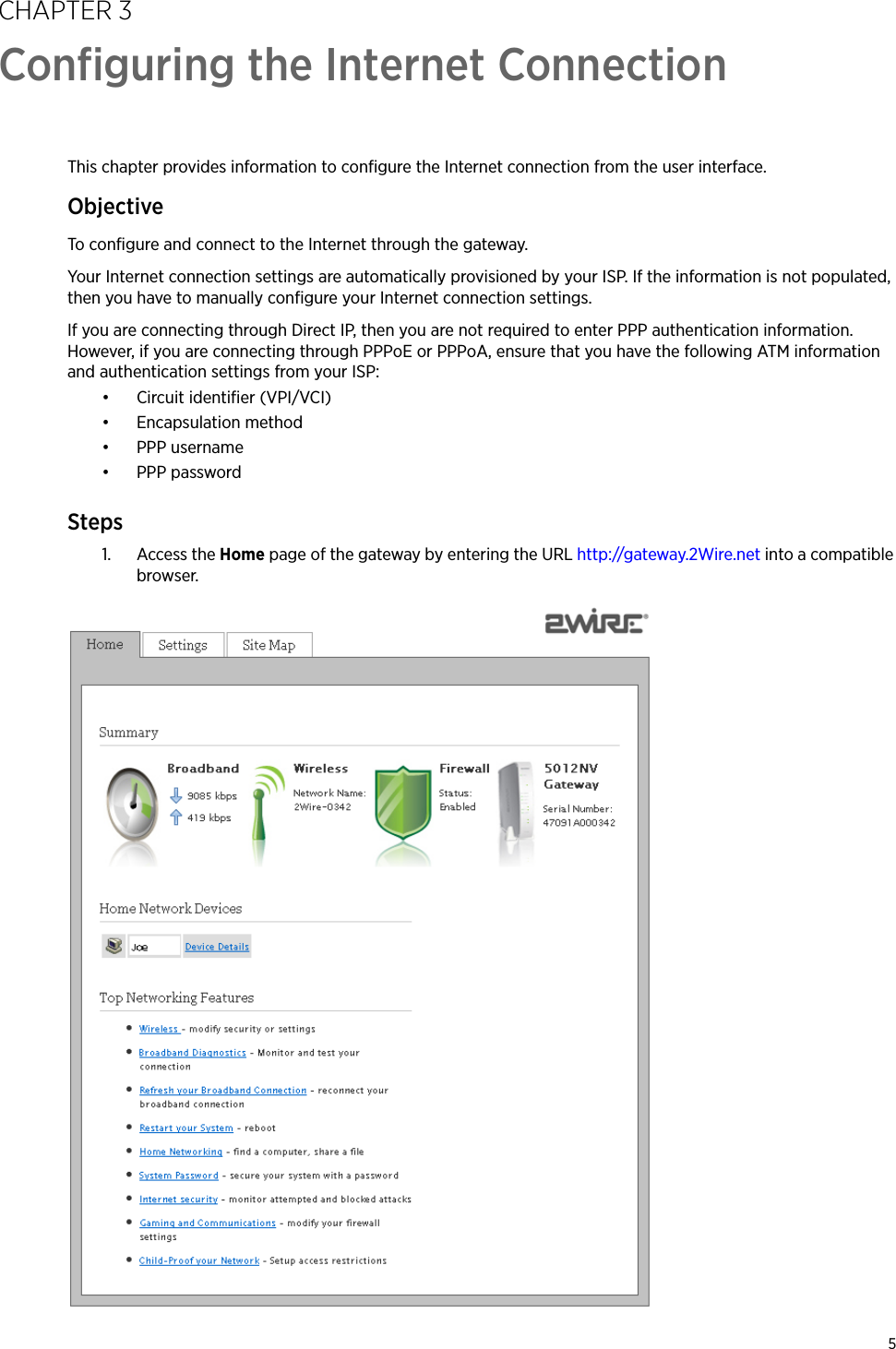
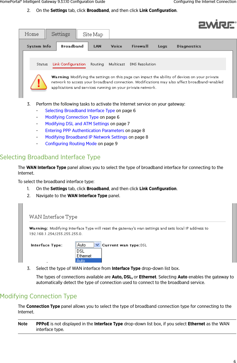
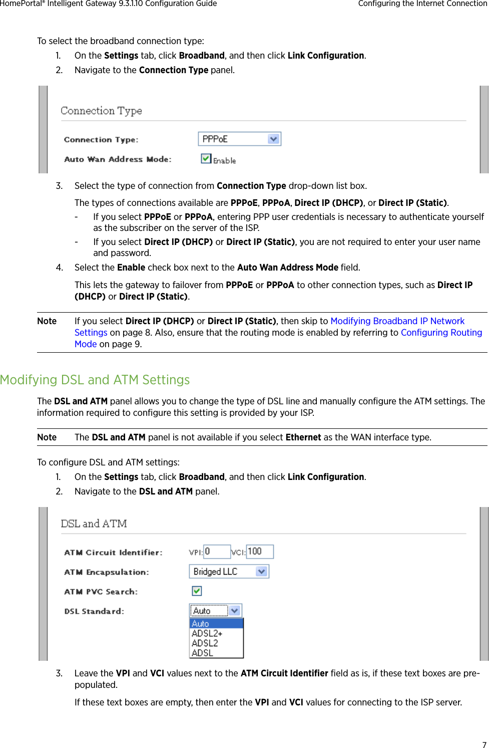
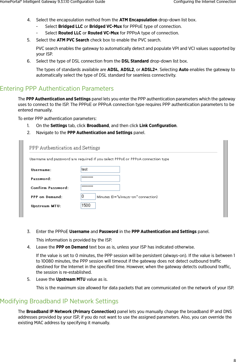
Pace Americas 2Wire Wireless 802.11n ADSL Residential Gateway 1
ARRIS >
Contents
- 1. User Manual 1
- 2. User Manual 2
- 3. Users Manual regulatory insert
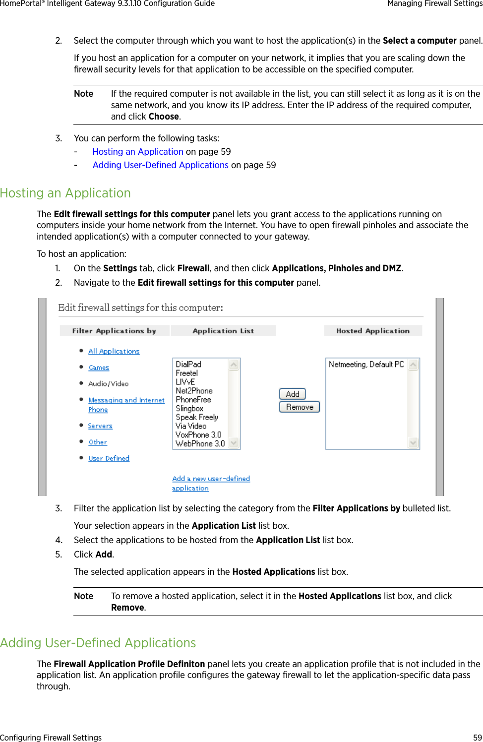
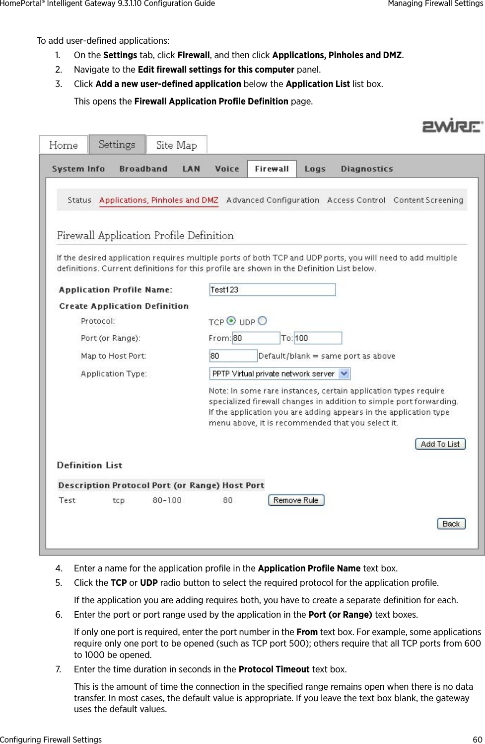
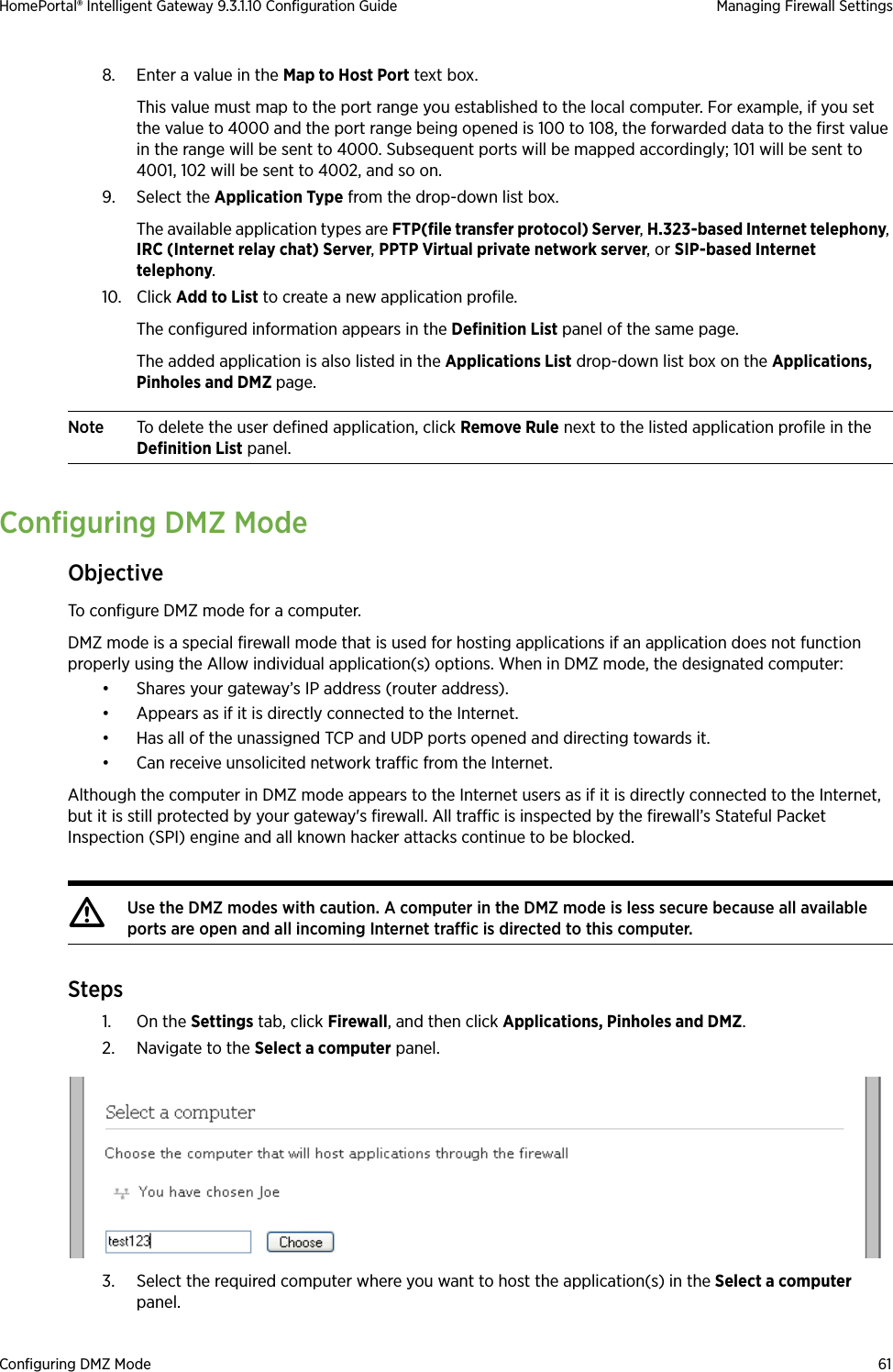
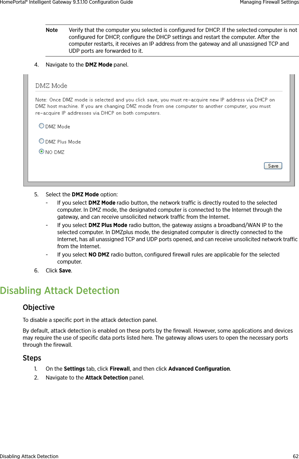
User Manual 1

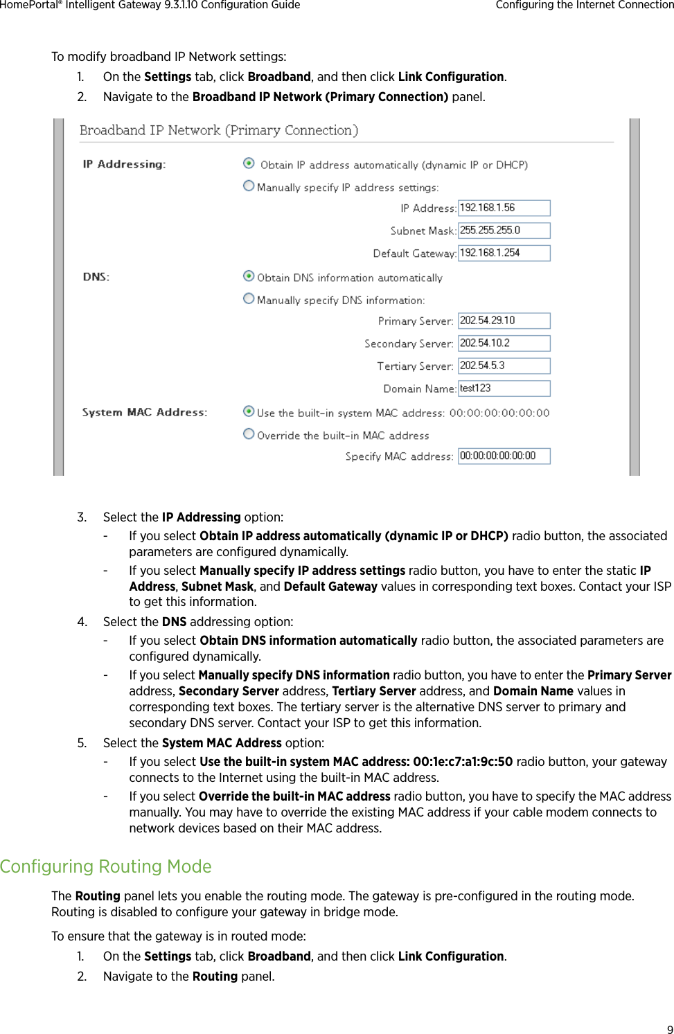
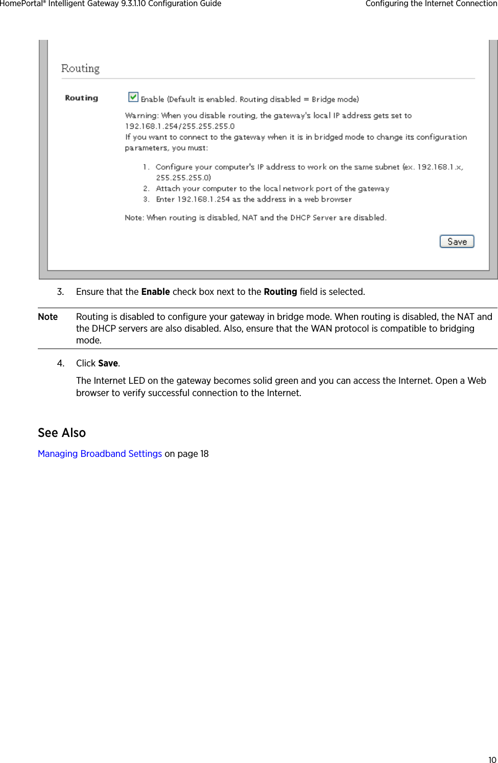
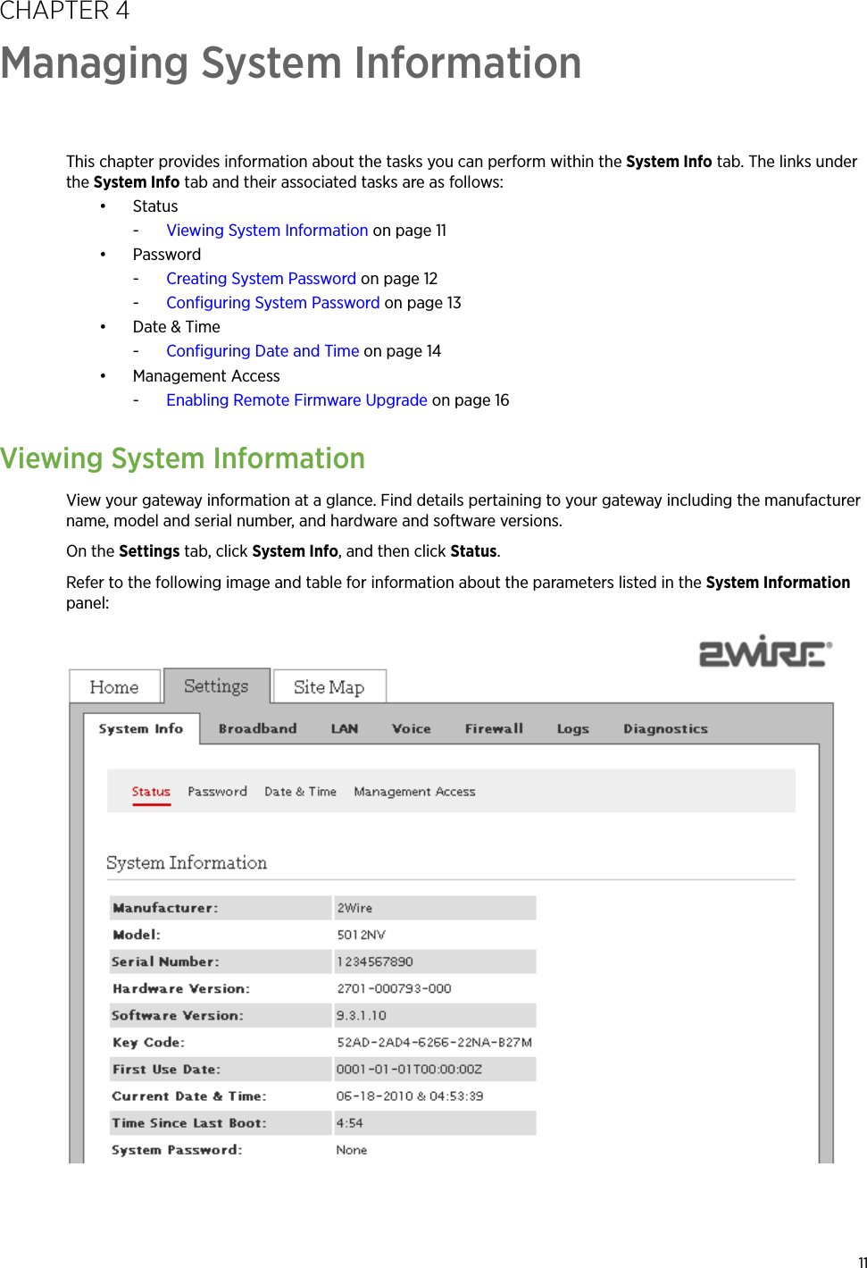
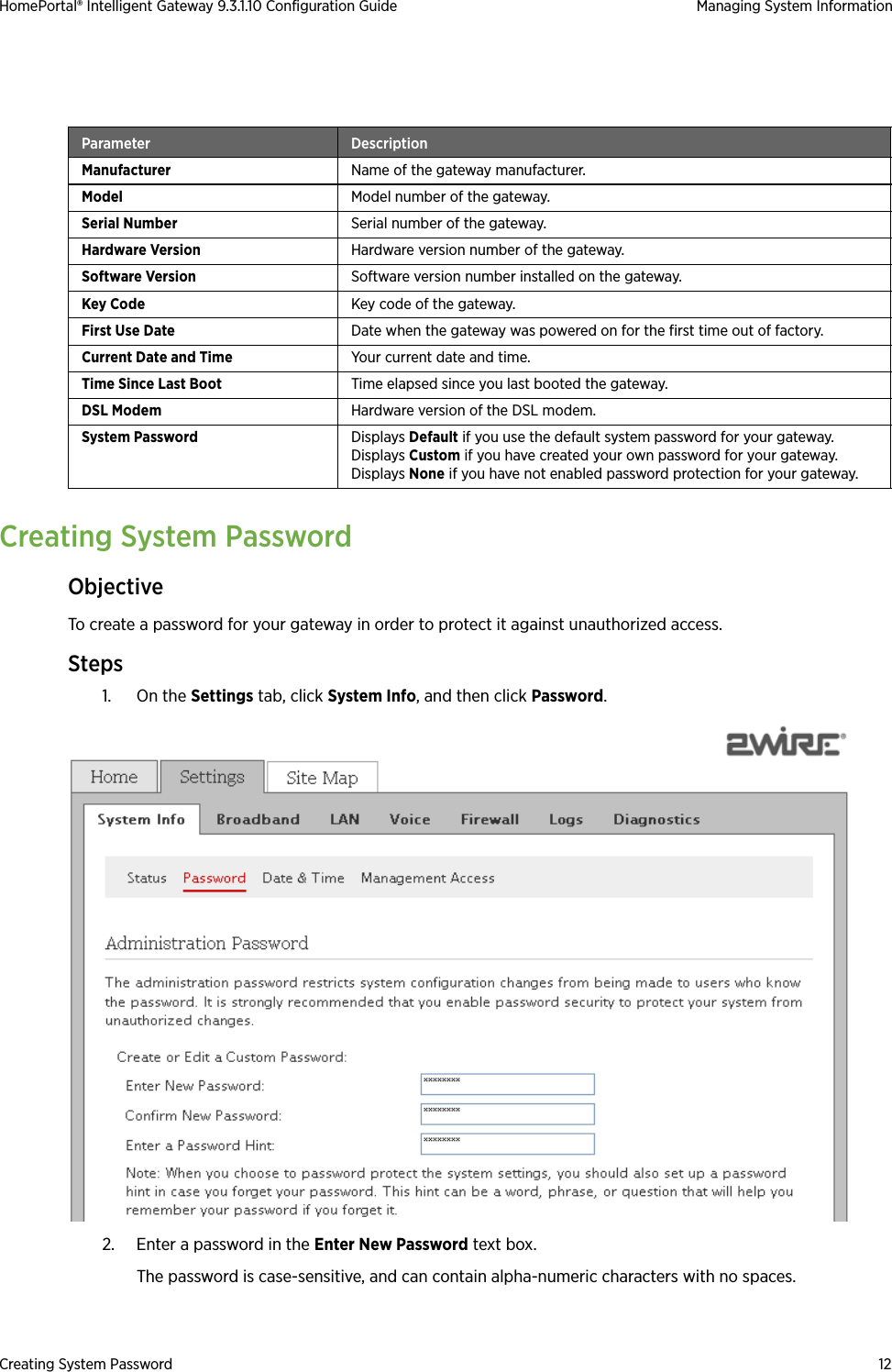


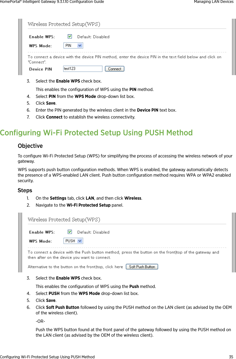
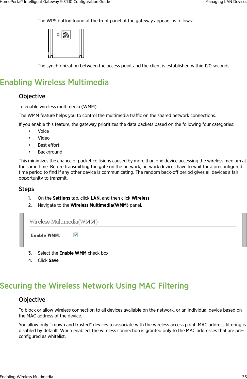
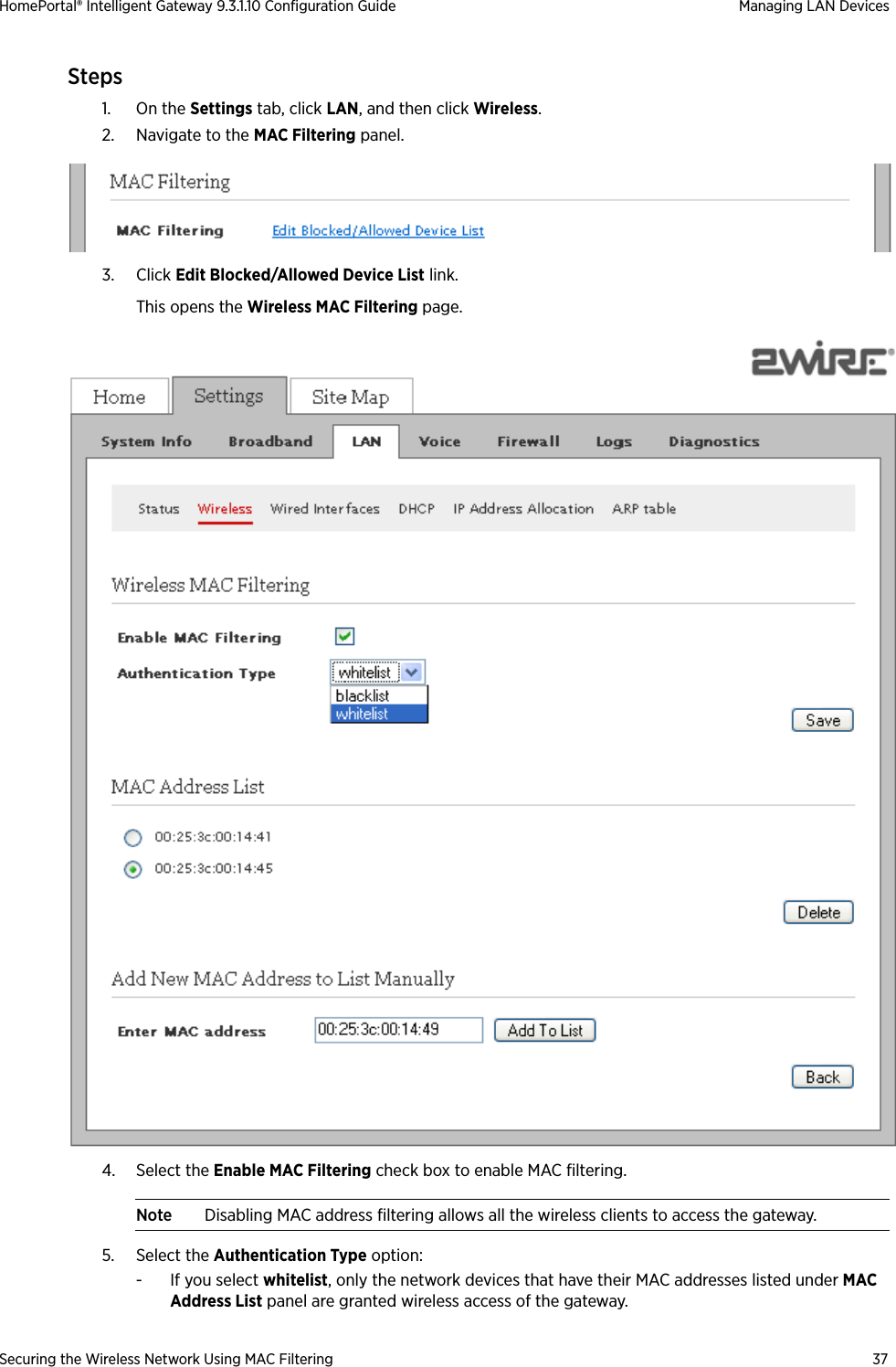
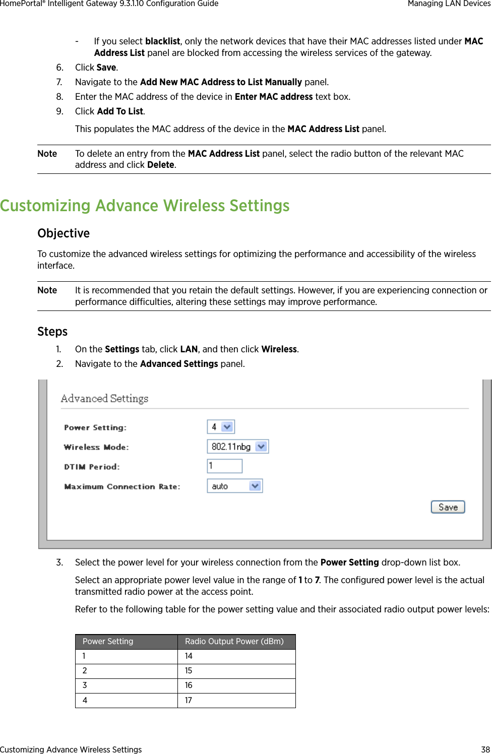
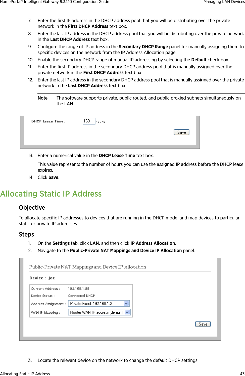
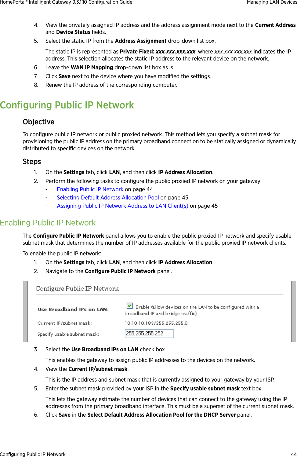
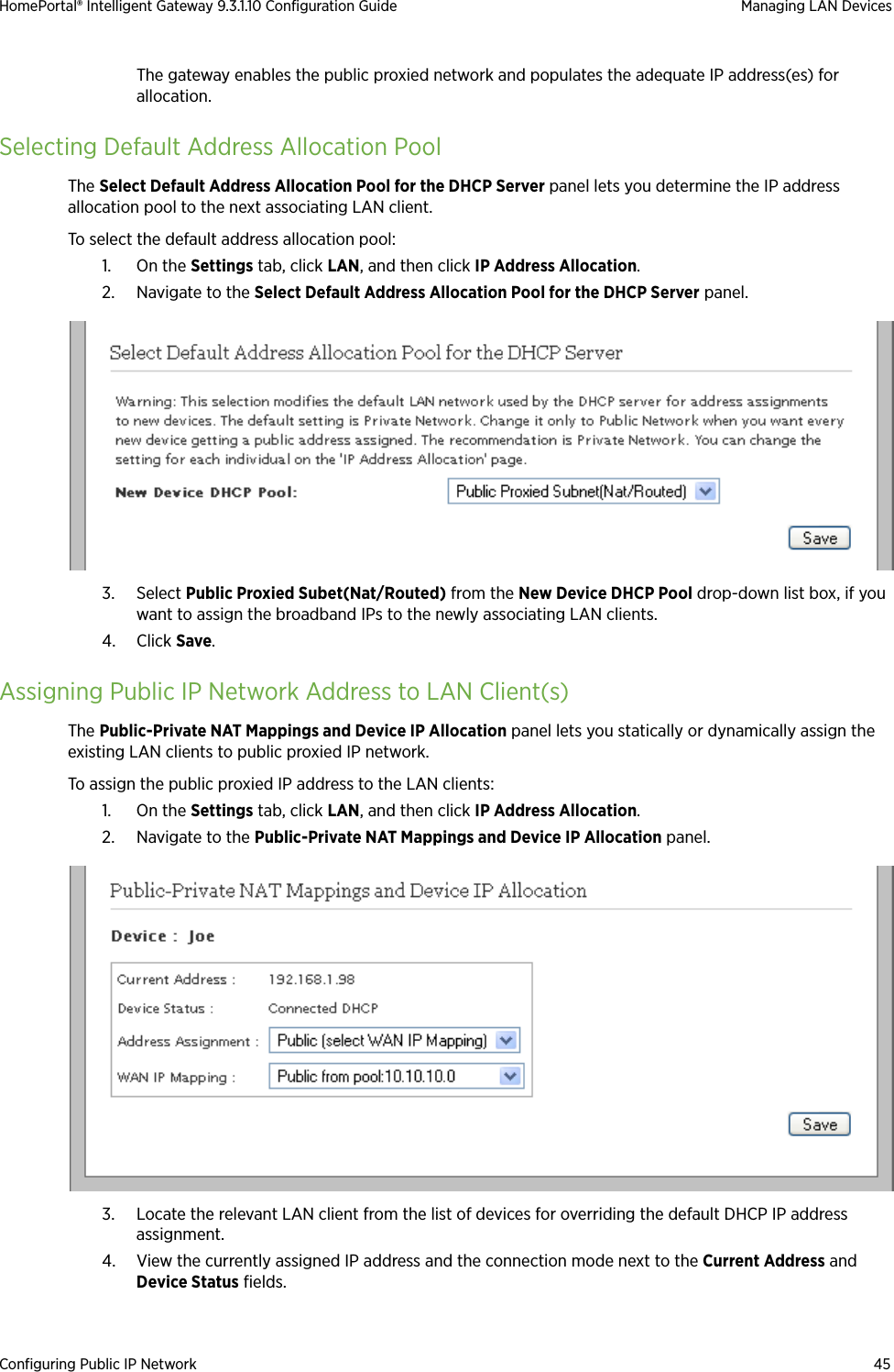
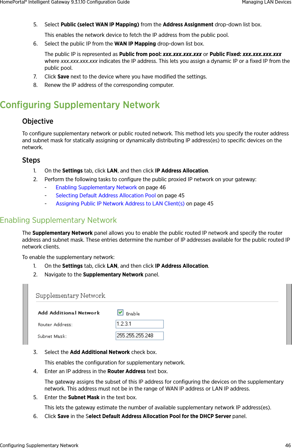
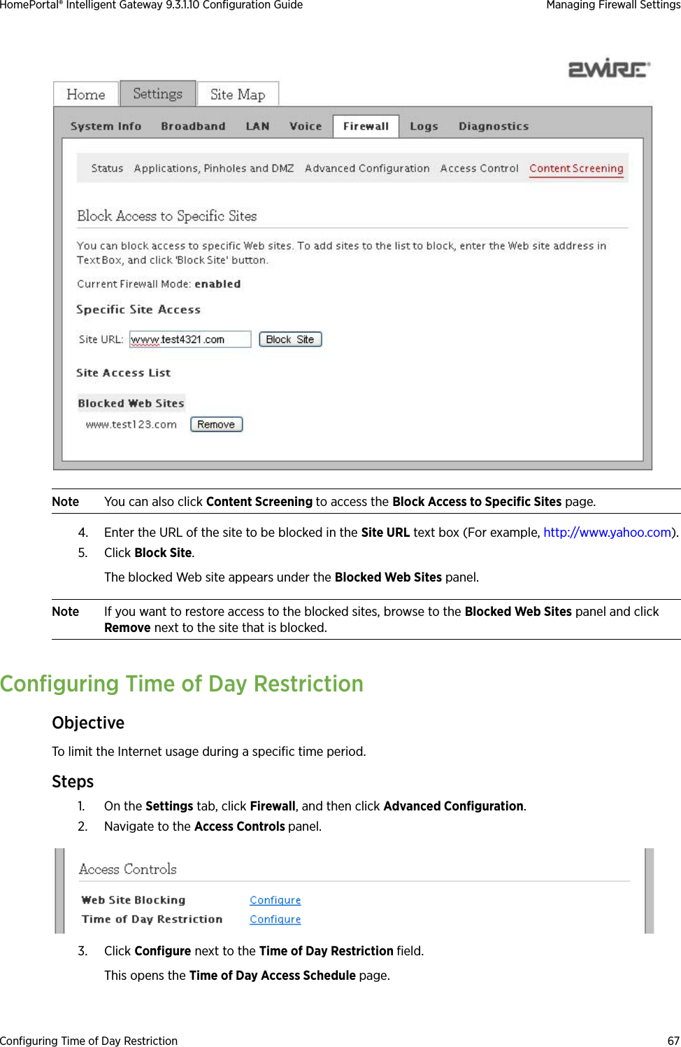
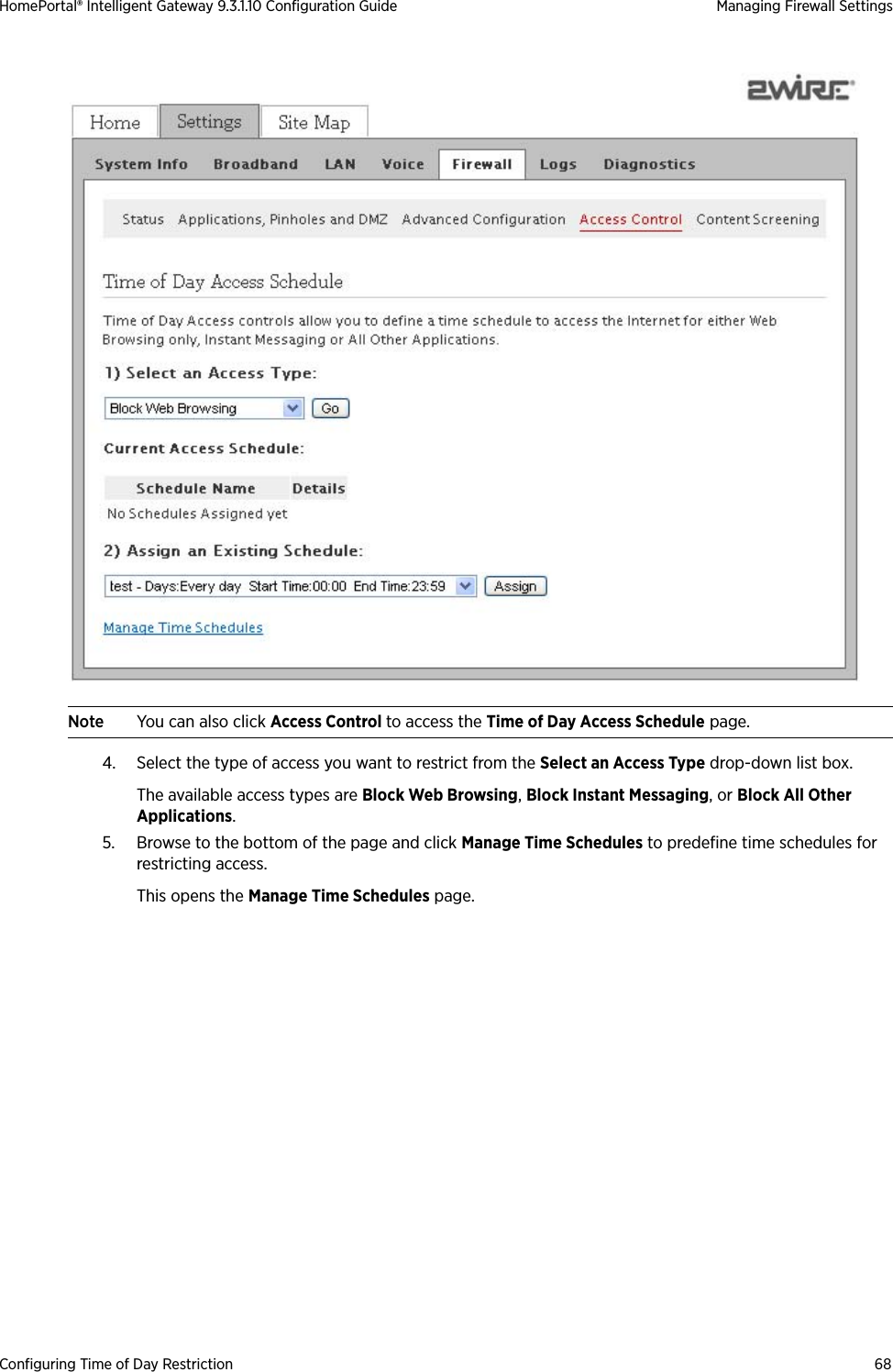
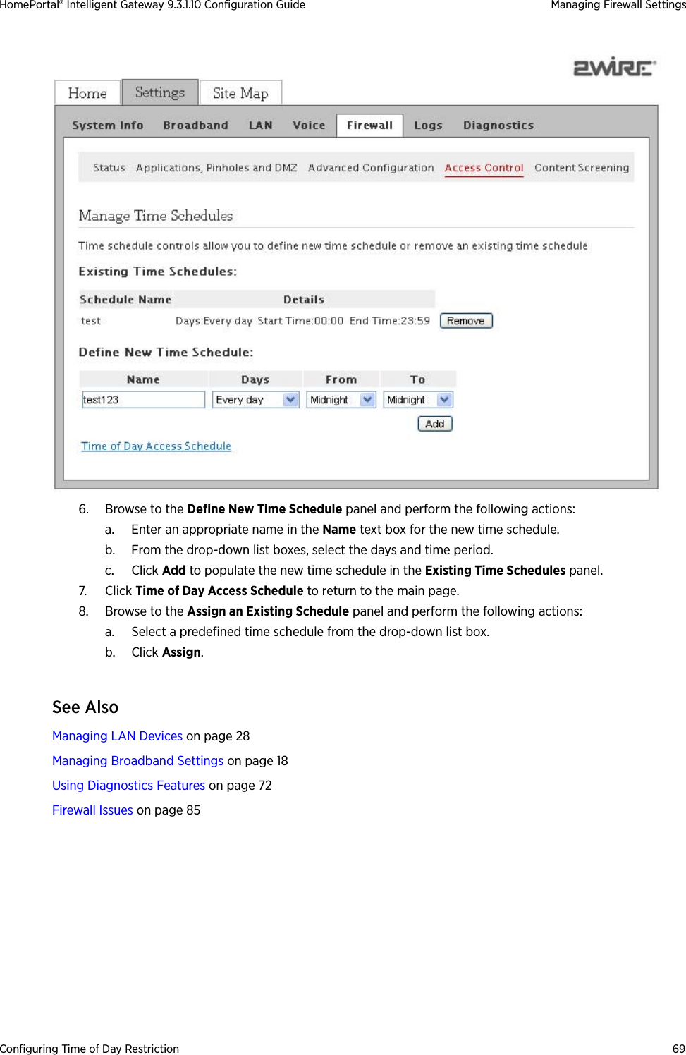
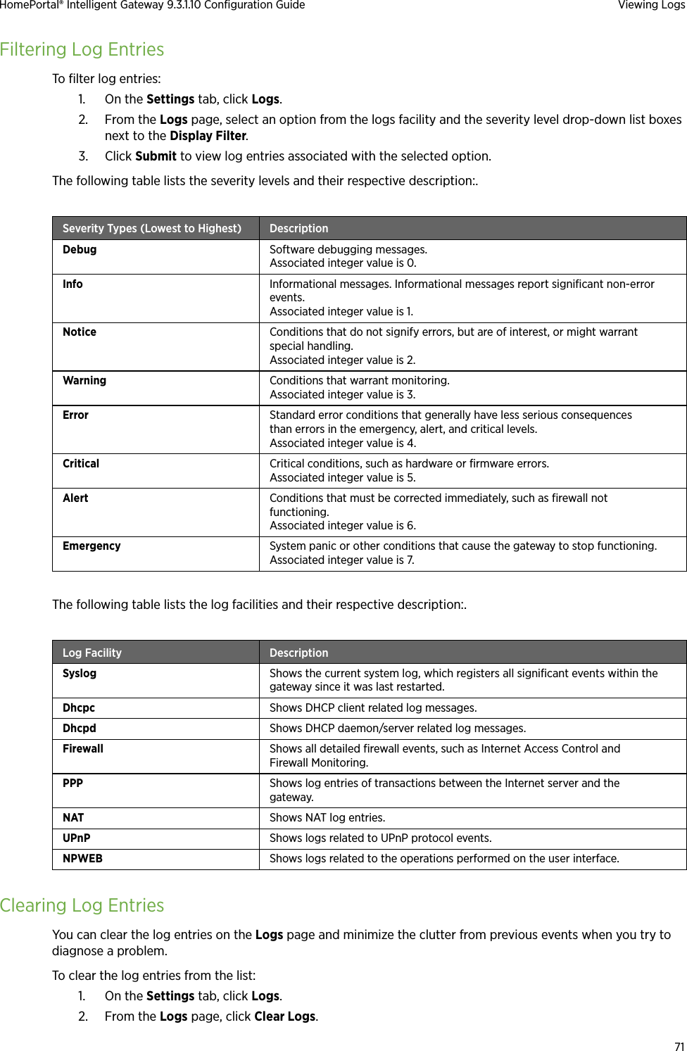
![70CHAPTER 9Viewing LogsThis chapter provides information to view, filter, and clear the log entries on the Logs Tab from the user interface.You can perform the following tasks on the Logs page:•Viewing Specific Log Entries on page 70•Filtering Log Entries on page 71•Clearing Log Entries on page 71Viewing Specific Log EntriesView log entries on this page to determine if there are any module specific issues or to ensure satisfactory performace of the device.On the Settings tab, click Logs.You can view log entries pertaining to a specifc module on this page, by selecting the desired module in the Display Filter list. The event logs are available in the following format:<3> Mar 10 07:41:16 home kern.err dhcpd_dns[2673]: [truncated]where <3> is the severity level, <Mar 10 07:41:16> is the time-stamp, <kern.err dhcpd_dns[2673]> is the module name, and <[truncated]> is the brief description of the log.](https://usermanual.wiki/ARRIS/2W5012NV.User-Manual-1/User-Guide-1312941-Page-77.png)