ARRIS 405ND 5 GHz 802.11n Wireless Video Bridge (AP/Station) User Manual user guide 405
Pace Americas 5 GHz 802.11n Wireless Video Bridge (AP/Station) user guide 405
ARRIS >
Contents
User Guide

USER GUIDE
Video Bridge
405

© 2013 Pace plc. All rights reserved.
Pace and the Pace logo are registered trademarks of Pace plc. All other trademarks are the property of their respective owners.
Pace provides no warranty with regard to this manual, the software, or other information contained herein, and hereby expressly
disclaims any implied warranties of merchantability or fitness for any particular purpose with regard to this manual, the software, or
such other information, in no event shall Pace be liable for any incidental, consequential, or special damages, whether based on tort,
contract, or otherwise, arising out of or in connection with this manual, the software, or other information contained herein or the use
thereof.
05162013
5100-001270-000
Version Date Description
1.0 04/05/2013 Initial version
1.1 04/11/2013 Revised installation procedures
1.2 05/10/13 Revised pairing procedures
Contents 3
Contents
Chapter 1 Introduction. . . . . . . . . . . . . . . . . . . . . . . . . . . . . . . . 4
Chapter 2 Setting up the video bridge. . . . . . . . . . . . . . . . . . . . 6
Connection overview . . . . . . . . . . . . . . . . . . . . . . . . . . . . . . . . . . . . . . . . . . . . . . . . . . . . . . . . . . . . . .6
Setting up the video bridge. . . . . . . . . . . . . . . . . . . . . . . . . . . . . . . . . . . . . . . . . . . . . . . . . . . . . . . . . .7
Connecting the video bridge to the gateway . . . . . . . . . . . . . . . . . . . . . . . . . . . . . . . . . . . . . . . . .7
Connecting power. . . . . . . . . . . . . . . . . . . . . . . . . . . . . . . . . . . . . . . . . . . . . . . . . . . . . . . . . . . . . .8
Connecting devices to the access point . . . . . . . . . . . . . . . . . . . . . . . . . . . . . . . . . . . . . . . . . . . . . . . .9
Connecting a wireless set-top box . . . . . . . . . . . . . . . . . . . . . . . . . . . . . . . . . . . . . . . . . . . . . . . . .9
Connecting a station. . . . . . . . . . . . . . . . . . . . . . . . . . . . . . . . . . . . . . . . . . . . . . . . . . . . . . . . . . .11
Connecting other devices . . . . . . . . . . . . . . . . . . . . . . . . . . . . . . . . . . . . . . . . . . . . . . . . . . . . . . .12
Locating the SSID and wireless network key . . . . . . . . . . . . . . . . . . . . . . . . . . . . . . . . . . . . . . . . . . .13
Chapter 3 Troubleshooting . . . . . . . . . . . . . . . . . . . . . . . . . . . 14
Appendix A Regulatory information. . . . . . . . . . . . . . . . . . . . . 16
4 Chapter 1 Introduction
Introduction 1
The Pace video bridge is a wireless access point that can be used to connect set-top
boxes or other devices to an existing gateway using a 5 GHz wireless connection.
The video bridge uses 802.11n 5 GHz high performance wireless technology to
provide a high bandwidth connection for video streams and other demanding
applications.
Pace wireless technology practically eliminates wireless “cold spots” in the home.
Increased power and sensitivity, along with optimized antenna design, give better
range and performance than typical 802.11n wireless access points.
405
AP
WIRELESS
ETHERNET
POWER
WPS

Chapter 1 Introduction 5
Status lights
Use the status lights on the front of the video bridge to determine its current state.
Status light Description
Power • Solid green. The video bridge is on.
•Red. The video bridge may have a fault with its power
supply. Check the power adapter and its connections.
Disconnect and reconnect the power adapter.
Ethernet • Solid green. A device is connected to the Ethernet port.
•Flickering green. There is activity from the device connected
to the Ethernet port. The flickering of the light is
synchronized to data traffic.
Wireless • Solid green. A set-top box or other device is connected to
the video bridge using a wireless connection.
•Flickering green. There is inbound or outbound activity. The
flickering of the light is synchronized to data traffic.
Wireless signal
strength
• Shows the strength of the wireless connection between the
video bridge and wireless devices. If more than one device is
connected, the indicator shows the strength of the device
with the weakest signal.
AP • Solid green. The video bridge is in access point mode.
•Flickering green. There is activity from a connected device.
The flickering of the light is synchronized to data traffic.
WPS • Flashing green. WPS (Wi-Fi Protected Setup) is configuring
the video bridge.
6 Chapter 2 Setting up the video bridge
Setting up the video
bridge 2
Connect the 405 video bridge to your existing gateway, then connect devices to the
video bridge using the 5 GHz wireless connection.
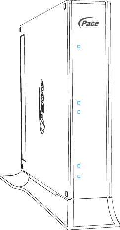
Note: We recommend that you use the included stand to install the video bridge
vertically. This prevents things from being stacked on top of it, which can block vents
and cause the device to overheat.
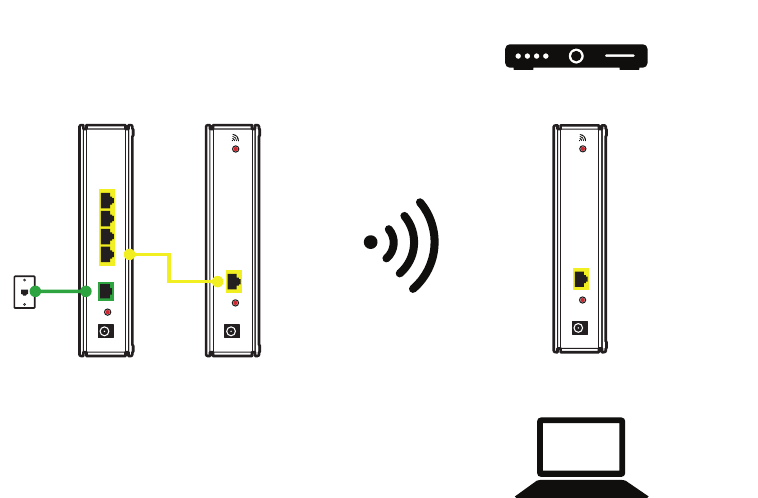
Connection overview
Connect the video bridge to the gateway using a wired connection, then connect
devices to the video bridge using a wireless connection.
The following illustration shows an overview of possible connections.
ETHERNET
POWER
RESET
43
2
1
DSL
BROADBAND
ETHERNET
POWER
RESET
WPS
ETHERNET
POWER
RESET
WPS
Gateway
Client devices
Video bridge
(access point)
Wireless
connection
Wireless
set-top box
Video bridge
(client)
Computer or
other device
Phone
outlet
Chapter 2 Setting up the video bridge 7
Setting up the video bridge
Connect the video bridge to your existing gateway. The gateway should be online
before you start this procedure. The video bridge will serve as a 5 GHz wireless
access point.
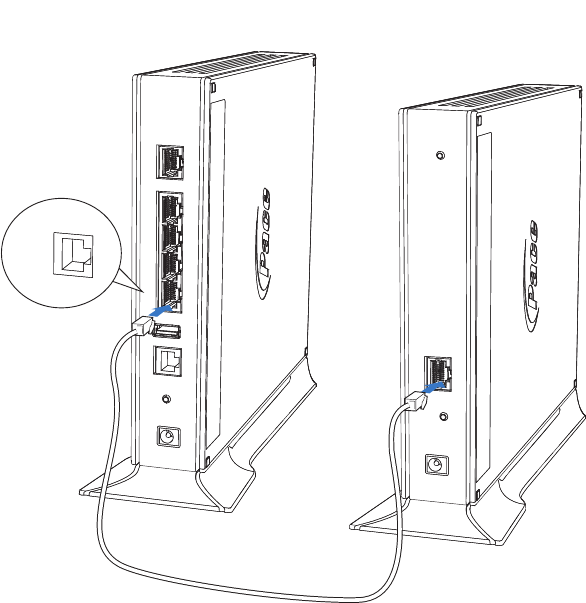
Connecting the video bridge to the gateway
Use the Ethernet port to connect the video bridge to your existing gateway.
1. Connect one end of the yellow Ethernet cable to an available yellow Ethernet port
on the gateway.
2. Connect the other end of the cable to the Ethernet port on the video bridge.
Note: A 6-foot yellow Ethernet cable is provided with the video bridge. If you need
another cable, use a Cat 5 or Cat 5e Ethernet cable.
Ethernet
Video bridge
(access point)
Gateway
8 Chapter 2 Setting up the video bridge
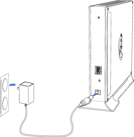
Connecting power
Use the power adapter that was packaged with the video bridge, because it matches
the power requirements for the device.
1. Connect one end of the power adapter to the Power port on the video bridge.
2. Connect the other end to a power outlet.
After the video bridge is powered on, the power light blinks green for a moment and
then turns steady green.
Chapter 2 Setting up the video bridge 9
Connecting devices to the access point
After the video bridge is configured as an access point, you can start connecting
devices to it using the 5 GHz wireless connection. You can connect one or more
devices to the access point.
Connecting a wireless set-top box
You can use the access point to connect to a wireless set-top box. With a wireless set-
top box, you can watch television almost anywhere in your home. Place your
television and set-top box just about anywhere, regardless of where existing TV
outlets are located.
1. Connect the wireless set-top box to your television. See the television or set-top
box documentation for more information.
2. Connect the power adapter for the wireless set-top box. The set-top box should
start automatically. Follow the instructions on the screen.
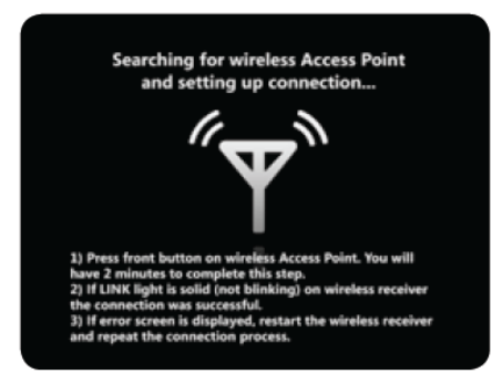
After a few minutes, you will see a message that the wireless set-top box is
searching for a wireless access point.
10 Chapter 2 Setting up the video bridge
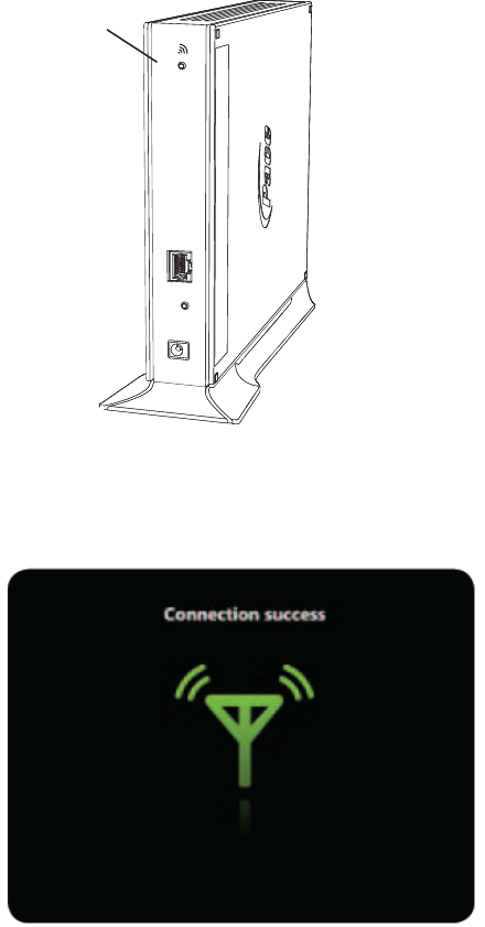
3. Press the WPS button on the back of the wireless access point. The WPS light on
the front of the access point will blink while the wireless set-top box connects to
the wireless access point.
After the set-top box connects to the access point, you will see the following message
on the television screen.
If the set-top box does not connect to the access point after a few minutes, see
“Connection issues” on page 14.
To add a second wireless set-top box, repeat the steps in this procedure.
WPS button
WPS
ETHERNET
RESET
POWER
Chapter 2 Setting up the video bridge 11
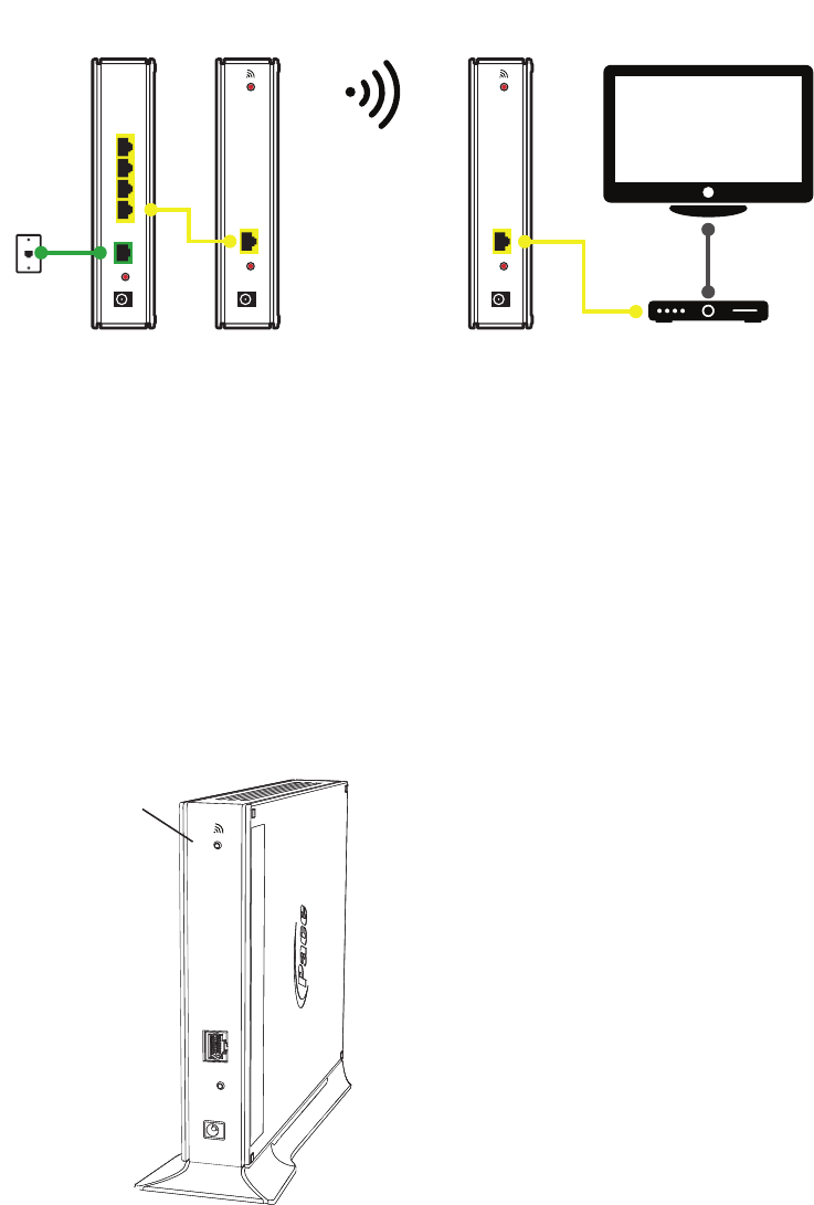
Connecting a station
The video bridge can also be used as a client device. In this scenario, you would have
two video bridges: the access point and the station. The access point is the video
bridge that is connected to the gateway, and the station is the one connected to the
set-top box.
1. Ensure that the wireless access point is connected and turned on. See “Setting up
the video bridge” on page 7.
2. Connect the station to the set-top box using the yellow Ethernet cable.
Note: A 6-foot yellow Ethernet cable is provided with the video bridge. If you need
another cable, use a Cat 5 or Cat 5e Ethernet cable.
3. Connect the power adapter for the station. See “Connecting power” on page 8.
4. Go to the wireless access point and press the WPS button on the back of the
device.
ETHERNET
POWER
RESET
43
2
1
DSL
BROADBAND
Gateway
Video bridge
(access point)
Video bridge
(station) TV
Set-top box
ETHERNET
POWER
RESET
WPS
ETHERNET
POWER
RESET
WPS
Phone
outlet
WPS button
WPS
ETHERNET
RESET
POWER
12 Chapter 2 Setting up the video bridge
5. Return to the station and press the WPS button on the back of the device.
The WPS lights on the front of the devices will blink while they search for each
other (discovery mode). The wireless access point and the station will stay in
discovery mode for up to two minutes while the devices try to establish a
connection.
If the station box does not connect to the wireless access point after a few
minutes, try this procedure again. If the devices still do not connect, see
“Connection issues” on page 14.
Connecting other devices
You can connect other wireless devices—such as tablets, mobile phones, or
notebooks—to the access point if you need a 5 GHz connection. By default, the
gateway is configured with a network name (SSID) and WPA-PSK/WPA2-PSK
security.
1. On the wireless device, view the available wireless networks. The specifics of how
you do this depend on the device you are connecting.
The SSID (default wireless network name) and wireless network key are printed
on the label on the side of the access point.
2. Select the appropriate wireless network name and connect.
3. At the prompt, enter the wireless network key.
After the gateway recognizes the wireless device, the Wireless light turns steady
green, and blinks when the wireless device starts transferring data with the gateway.
Chapter 2 Setting up the video bridge 13
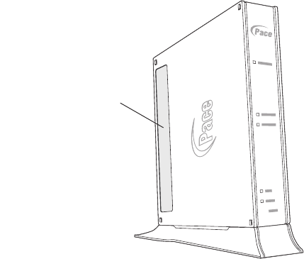
Locating the SSID and wireless network key
The SSID (network name) and wireless network key are printed on the label on the
side of the video bridge.
SSID and
wireless network key
14 Chapter 3 Troubleshooting
Troubleshooting 3
This section provides information about common installation issues. If an issue has
more than one potential cause, the most common cause is listed first.
Power issues
Use the information in this section to identify and resolve issues related to power.
The Power light is not on
•The power cable may be loose or disconnected. Check the power cable to ensure
that the cable is securely connected. If the power cable is plugged in to a power
strip or switched outlet, ensure that it is on. Ensure that you are using the power
supply that came with the video bridge.
•The power supply may be faulty. Verify that the light on the power supply is green.
•The AC outlet may be faulty. Try plugging the video bridge in to a known good
outlet.
The Power light blinks immediately after the device starts, and then turns steady
green
•The Power light blinks during POST (Power on self-test). This is normal behavior.
The Power light is red
•The POST (Power on self-test) may have failed. Press the Reset button and hold it
for 10 seconds to reset the video bridge.
Connection issues
Use the information in this section to identify and resolve issues related to
connectivity.
The Ethernet light is not on
•The Ethernet cable may be loose or disconnected. Check the connections to
ensure that the cable is securely connected.
Chapter 3 Troubleshooting 15
A wireless set-top box or other device cannot connect to the access point
•Ensure that you have a strong enough signal. At least three green bars should
appear on the signal strength indicator on the set-top box.
•Ensure that you have waited long enough for the set-top box to start and to
connect. This can take up to ten minutes.
•If you see a red antenna on the television screen, restart the wireless set-top box
and try to connect again.
The Wireless light is not on
•No devices are currently connected to the video bridge over the wireless
connection.
•Ensure that the wireless feature is enabled. For more information, go to the video
bridge configuration page at http://192.168.1.200.
A wireless device cannot get an IP address
•The device may not be set up with the appropriate security type or security key.
Ensure that the wireless device is using the appropriate credentials.
The wireless signal is weak
•The wireless device may be out of range. Ensure that the wireless device is within
the range of the video bridge.
16 Appendix A Regulatory information
Regulatory information A
Declaration of conformity
The following sections describe regulatory compliance by region.
FCC / Industry Canada Compliance
This device has been tested and certified as compliant with the regulations and
guidelines set forth in the Federal Communication commission - FCC part 15 and
Industry Canada - ICES003 and RSS-210 Radio and telecommunication regulatory
requirements.
Le présent materiel est conforme aux specifications techniques applicables d'Industrie
Canada. Cet appareil numérique de la classe [*] est conforme à la norme NMB-003 du
Canada.
Manufacturer: Pace
Model(s): 405
Part 15 of FCC Rules / IC RSS-210
This device complies with part 15 of the FCC Rules and Industry Canada license-
exempt RSS standard(s). Operation is subject to the following two conditions:
(1) this device may not cause harmful interference, and (2) this device must accept
any interference received, including interference that may cause undesired operation
of the device.
Le présent appareil est conforme aux normes CNR d'Industrie Canada applicables
aux appareils radio exempts de licence. L'exploitation est autorisée aux deux
conditions suivantes:
(1) l'appareil ne doit pas produire de brouillage, et (2) l'utilisateur de l'appareil doit
accepter tout brouillage radioélectrique subi, même si le brouillage est susceptible
d'en compromettre le fonctionnement.
This equipment has been tested and found to comply with the limits for a Class B
digital device, pursuant to part 15 of the FCC Rules. These limits are designed to
provide reasonable protection against harmful interference in a residential installation.
This equipment generates uses and can radiate radio frequency energy and, if not
installed and used in accordance with the instructions, may cause harmful
interference to radio communications. However, there is no guarantee that
interference will not occur in a particular installation. If this equipment does cause
Appendix A Regulatory information 17
harmful interference to radio or television reception, which can be determined by
turning the equipment off and on, the user is encouraged to try to correct the
interference by one or more of the following measures:
•Reorient or relocate the receiving antenna.
•Increase the separation between the equipment and receiver.
•Connect the equipment into an outlet on a circuit different from that to which the
receiver is connected.
•Consult the dealer or an experienced radio/TV technician for help.
CAUTION: Changes or modifications not expressly approved by the party responsible
for compliance could void your authority to operate this equipment. Failure to heed the
Safety Information provided by failing to connect to a properly wired outlet may void
the manufacturer's warranty.
MPE/SAR/RF exposure information
This device was verified for RF exposure and found to comply with Council
Recommendation 1999/519/EC and FCC OET-65 RF exposure requirements. This
equipment complies with FCC radiation exposure limits set forth for an uncontrolled
environment.
WARNING: While this device is in operation, a separation distance of at least 20 cm
(8 inches) must be maintained between the radiating antenna inside the EUT and the
bodies of all persons exposed to the transmitter in order to meet the FCC RF
exposure guidelines. Making changes to the antenna or the device is not permitted.
Doing so may result in the installed system exceeding RF exposure requirements.
This device must not be co-located or operated in conjunction with any other antenna
or radio transmitter.
Electrical—AC adapter
This product is intended to be supplied with a listed Pace Direct Plug-In AC/DC Power
adapter marked Class 2 or LPS and rated 12 V,1.5 A for all 405-xxx models.
The AC/DC Power adapter supplied with this product is designed to ensure your
personal safety and to be compatible with this equipment.
18 Appendix A Regulatory information
Please follow these guidelines:
•Do not use the adapter in a high moisture environment. Never touch the adapter
when your hands or feet are wet.
•Allow adequate ventilation around the adapter. Avoid locations with restricted
airflow.
•Connect the adapter to a proper power source. The voltage and grounding
requirements are found on the product case and/or packaging.
•Do not use the adapter if the cord becomes damaged.
•Do not attempt to service the adapter. There are no serviceable parts inside.
Replace the unit if it is damaged or exposed to excess moisture.
Equipment
Location—Electrical considerations
CAUTION: Due to risk of electrical shock or damage, do not use this product near
water, including a bathtub, wash bowl, kitchen sink or laundry tub, in a wet basement,
or near a swimming pool. Also, avoid using this product during electrical storms. Avoid
locations near electrical appliances or other devices that cause excessive voltage
fluctuations or emit electrical noise (for example, air conditioners, neon signs, high-
frequency or magnetic security devices, or electric motors).
Location—Environmental considerations
Do not plug the AC/DC power adapter into an outdoor outlet or operate the product
outdoors. It is not waterproof or dustproof, and is for indoor use only. Any damage to
the unit from exposure to rain or dust may void your warranty.
Do not use the product where there is high heat, dust, humidity, moisture, or caustic
chemicals or oils. Keep the gateway away from direct sunlight and anything that
radiates heat, such as a stove or a motor.
Repairs
Do not, under any circumstances, attempt any service, adjustments, or repairs on this
equipment. Instead, contact your local Pace Americas distributor or service provider
for assistance. Failure to comply may void the product warranty.