ARRIS BGW210 BGW210-700 ARRIS uDSL Wireless Residential Gateway User Manual Install and Operations Guide
ARRIS BGW210-700 ARRIS uDSL Wireless Residential Gateway Install and Operations Guide
ARRIS >
User Manual

BGW210-700 Broadband Gateway
Release 1.0
Install and Operations Guide
365-095-30882 Revision 4.0
November 2016
ARRIS Copyrights and Trademarks
ARRIS Copyrights and Trademarks
© 2016 ARRIS Enterprises LLC. All Rights Reserved.
No part of this publication may be reproduced in any form or by any means or used to make
any derivative work (such as translation, transformation, or adaptation) without written
permission from ARRIS Enterprises LLC. (“ARRIS”). ARRIS reserves the right to revise this
publication and to make changes in content from time to time without obligation on the part
of ARRIS to provide notification of such revision or change.
ARRIS and the ARRIS logo are all trademarks of ARRIS Enterprises LLC. Other trademarks and
trade names may be used in this document to refer to either the entities claiming the marks
or the names of their products. ARRIS disclaims proprietary interest in the marks and names
of others.
ARRIS provides this guide without warranty of any kind, implied or expressed, including, but
not limited to, the implied warranties of merchantability and fitness for a particular purpose.
ARRIS may make improvements or changes in the product(s) described in this manual at any
time.
The capabilities, system requirements and/or compatibility with third-party products
described herein are subject to change without notice.

365-095-30882 Revision 4.0 BGW210-700 Broadband Gateway Release 1.0 Install and Operations Guide
© 2016 ARRIS Enterprises LLC. All Rights Reserved. 3
Table of Contents
1. ARRIS BGW210-700 Broadband Gateway Introduction ............................................ 5
About ARRIS Documentation ............................................................................................. 5
Documentation Hyperlinks ................................................................................................ 5
Related Documentation..................................................................................................... 6
Document Organization .................................................................................................... 6
2. Preliminary Safety Instructions ................................................................................ 7
Power Supply Installation .................................................................................................. 7
Telecommunication Installation ........................................................................................ 8
Product Ventilation ............................................................................................................ 8
3. Hardware Gateway Installation ............................................................................... 9
Connecting the Power Adapter ....................................................................................... 11
Connecting Computers to the BGW210-700 Broadband Gateway ................................ 11
Connecting Devices Using Wired Ethernet ...................................................................... 11
Connecting Devices Using Wi-Fi ...................................................................................... 12
Connecting the BGW210-700 Broadband Gateway to the Internet ............................... 13
Connecting VoIP Telephones ........................................................................................... 14
4. Basic Troubleshooting ........................................................................................... 16
Status Indicator Lights ..................................................................................................... 17
Problem Isolation .................................................................................................... 21
Rear Panel Connectors .................................................................................................... 23
Factory Reset Switch ....................................................................................................... 24
5. Technical Specifications and Safety Information .................................................... 25
Dimensions and Interfaces .............................................................................................. 25
Power Supply ................................................................................................................... 26
Environment .................................................................................................................... 26
Agency Approvals ............................................................................................................ 26
North America ......................................................................................................... 26
Caring for the Environment by Recycling ........................................................................ 26
6. Important Safety Instructions ................................................................................ 27
WARNINGS ....................................................................................................................... 27
Product Ventilation .......................................................................................................... 27
Telecommunication Installation Cautions ....................................................................... 27
Electrical Safety Advisory................................................................................................. 28
Declaration of Conformance ........................................................................................... 28

365-095-30882 Revision 4.0 BGW210-700 Broadband Gateway Release 1.0 Install and Operations Guide
© 2016 ARRIS Enterprises LLC. All Rights Reserved. 4
47 CFR Part 68 Information .................................................................................... 28
FCC Caution ...................................................................................................................... 29
Radiation Exposure Statement ........................................................................................ 29
Service Requirements ...................................................................................................... 30
7. ARRIS Contacts ...................................................................................................... 31

365-095-30882 Revision 4.0 BGW210-700 Broadband Gateway Release 1.0 Install and Operations Guide
© 2016 ARRIS Enterprises LLC. All Rights Reserved. 5
Chapter 1
ARRIS BGW210-700 Broadband Gateway
Introduction
The BGW210-700 Broadband Gateway hardware platform can host different software. The
Advanced Residential Gateway supports VoIP, IPv6, video delivery, security firewall, and
extensive remote management features.
The BGW210-700 Broadband Gateway delivers robust video, primary line telephony, and high-
speed data over broadband networks via high-speed Internet connectivity. The four Gigabit
Ethernet ports can be separated into different services allowing the configuration of dedicated
ports for data. It is designed for advanced DSL network service deployments and supports
Quality of Service (QoS) enabled features including:
Simultaneous use of phone, video, and high-speed data over any one of the available WAN
interfaces
IPTV video
Concurrent Wi-Fi support for 3x3 802.11n on 2.4GHz, and 4x4 802.11ac on 5GHz
Primary line VoIP telephone service
About ARRIS Documentation
This guide presents basic operational concepts, and provides step-by-step instructions for the
hardware installation and basic troubleshooting of the ARRIS BGW210-700 Broadband
Gateway.
Note: For the purposes of this manual the ARRIS BGW210-700 Broadband Gateway may also
be referred to simply as the gateway.
Documentation Hyperlinks
The hyperlink resides in the page number that follows the title. For example, to access
Hardware Gateway Installation in the hyperlink below, hover the mouse over the page
number in parenthesis until the finger pointer appears, and then click.
Hardware Gateway Installation (page 9)

Chapter 1: ARRIS BGW210-700 Broadband Gateway Introduction
365-095-30882 Revision 4.0 BGW210-700 Broadband Gateway Release 1.0 Install and Operations Guide
© 2016 ARRIS Enterprises LLC. All Rights Reserved. 6
Related Documentation
BGW210-700 Broadband Gateway reference documentation is as follows:
BGW210-700 Broadband Gateway Install and Operations Guide (this document)
BGW210-700 Broadband Gateway AT&T Software Administrator's Handbook
ARRIS ENB-17244 (select BGW210-700 Hardware Diagnostics Information)
Document Organization
This hardware install and operation guide consists of six product information chapters
presented as follows:
ARRIS BGW210-700 Broadband Gateway Introduction (page 5) — Describes the ARRIS®
document suite, purpose, and structure of this guide.
Preliminary Safety Instructions (page 7) — Provides power supply, telecommunication, and
ventilation safety instructions.
Hardware Gateway Installation (page 9) — Provides the rear panel illustration, a cabling
overview, and procedures to perform BGW210-700 Broadband Gateway connections for
the power adapter, wired Ethernet, wireless devices, Internet, and VoIP telephones.
Basic Troubleshooting (page 16) — Provides simple suggestions for troubleshooting
problems with the initial configuration of the gateway.
Technical Specifications (page 25) — Presents system and device specifications and
important compliance and safety statements.
Important Safety Instructions (page 27) — Provides product, telecommunication, and
electrical cautionary information, as well as conformance, radiation, and gateway
disposable information.

365-095-30882 Revision 4.0 BGW210-700 Broadband Gateway Release 1.0 Install and Operations Guide
© 2016 ARRIS Enterprises LLC. All Rights Reserved. 7
Chapter 2
Preliminary Safety Instructions
Warning: Do not use before reading these instructions.
Do not connect the Ethernet ports to a carrier or carriage service provider’s
telecommunications network or facility unless:
You have the written consent of the network or facility manager, or
The connection is in accordance with a connection permit or connection rules.
Connection of the Ethernet ports may cause a hazard or damage to the telecommunication
network or facility, or persons, with consequential liability for substantial compensation.
Power Supply Installation
Connect the power supply cord to the power jack on the BGW210-700 Broadband Gateway.
Plug the power supply into an appropriate electrical outlet.
Warning: The power supply must be connected to a mains outlet with a protective earth
connection. Do not defeat the protective earth connection.
Warning: Use only the power supply and cord that came with the BGW210-700 Broadband
Gateway. Failure to use the authorized power supply and cord may cause electric shock, fire,
bodily injury, and/or property damage. If the power supply or cord becomes damaged or
needs to be replaced, to obtain an authorized replacement please contact AT&T customer
service by phone (1.800.288.2020) or via website (www.att.com/support).
Caution: Depending on the power supply provided with the product, either the direct plug-in
power supply blades, power supply cord plug or the appliance coupler serves as the mains
power disconnect. It is important that the direct plug-in power supply, socket-outlet or
appliance coupler be located so it is readily accessible.

Chapter 2: Preliminary Safety Instructions
365-095-30882 Revision 4.0 BGW210-700 Broadband Gateway Release 1.0 Install and Operations Guide
© 2016 ARRIS Enterprises LLC. All Rights Reserved. 8
Telecommunication Installation
When using telephone equipment, basic safety precautions should always be followed to
reduce the risk of fire, electric shock, and injury, including the following:
This device is intended for indoor use only.
Warning: Do not install this gateway outdoors.
Warning: Installing and operating this gateway outdoors is a violation of FCC rules.
Do not use this product near water, for example, near a bathtub, washbowl, and kitchen
sink or laundry tub, in a wet basement or near a swimming pool.
Avoid using a telephone (other than a cordless type) during an electrical storm. There may
be a remote risk of electrical shock from lightning.
Do not use the telephone to report a gas leak in the vicinity of the leak.
Caution: The external phone should be UL listed, and the connections should be made in
accordance with Article 800 of the National Electric Code (NEC).
Caution: To reduce the risk of fire, use only No. 26 AWG or larger telecommunication line
cord.
Product Ventilation
The BGW210-700 Broadband Gateway is intended for use in a consumer's home. Position the
device in an upright vertical position located where ambient temperatures remain within a
range of 32°- 107°F (0°- 41.7°C). The BGW210-700 Broadband Gateway should not be used in
locations exposed to outside heat radiation or where it is subject to trapping of its own heat.
The product should have at least two inches of clearance on all sides except the bottom when
properly installed and should not be placed inside tightly enclosed spaces unless proper
ventilation is provided.
SAVE THESE INSTRUCTIONS
Chapter 3: Hardware Gateway Installation
365-095-30882 Revision 4.0 BGW210-700 Broadband Gateway Release 1.0 Install and Operations Guide
© 2016 ARRIS Enterprises LLC. All Rights Reserved. 9
Chapter 3
Hardware Gateway Installation
A BGW210-700 Broadband Gateway cabling overview, as well as rear panel illustration, is
provided below. Also provided are procedures to perform BGW210-700 Broadband Gateway
connections for the power adapter, wired Ethernet, wireless devices, Internet, and VoIP
telephones.
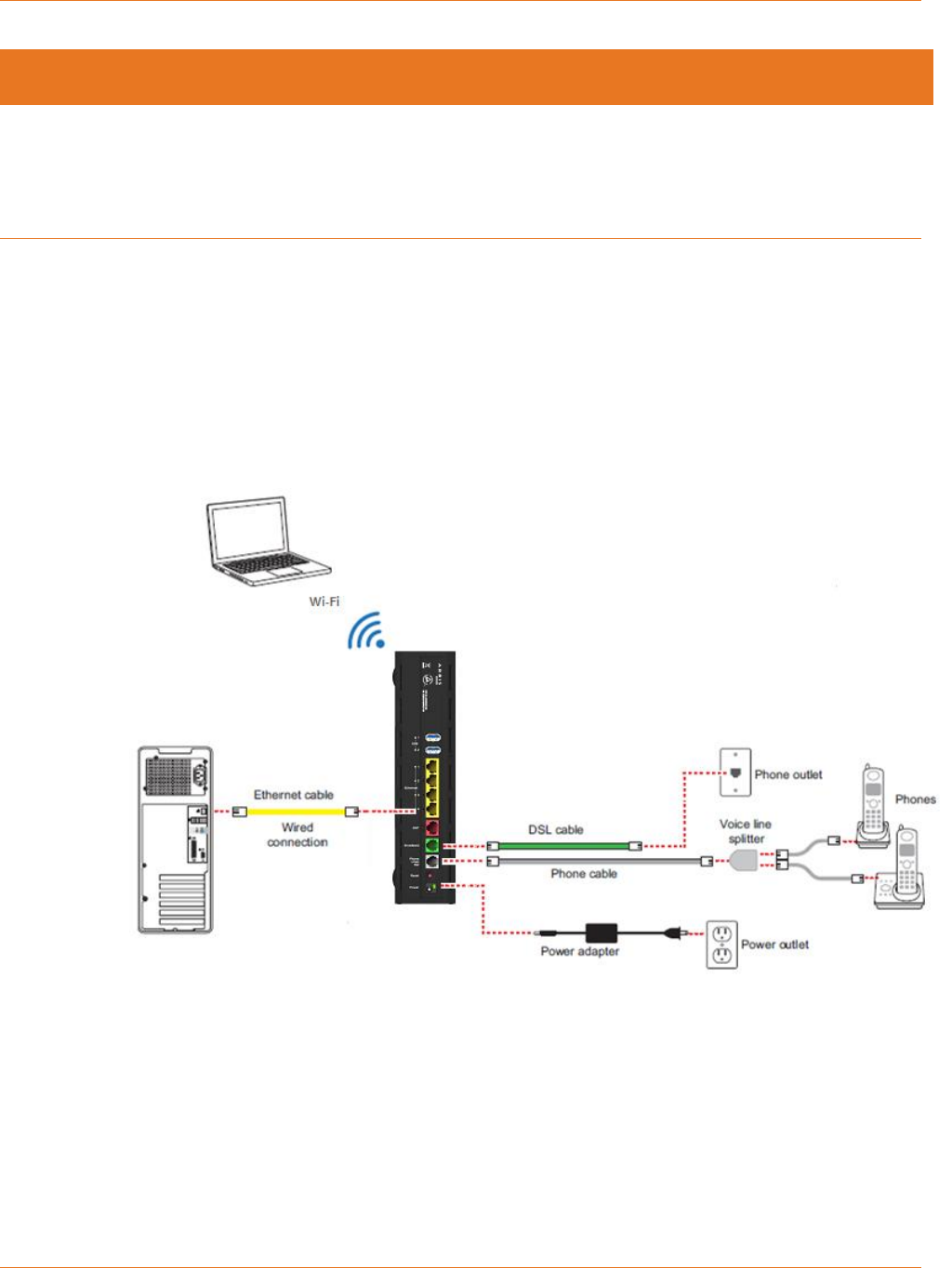
The following diagram illustrates BGW210-700 Broadband Gateway connections to the
Internet using DSL Broadband. Phone and power adapter connections are also illustrated.
BGW210-700 Broadband Gateway Cabling Overview
Alternatively, you can connect the BGW210-700 Broadband Gateway to the Internet using the
WAN Ethernet port labeled ONT. See Connecting the BGW210-700 Broadband Gateway to the
Internet (page 13) for the detailed procedures regarding this setup.
Chapter 3: Hardware Gateway Installation
365-095-30882 Revision 4.0 BGW210-700 Broadband Gateway Release 1.0 Install and Operations Guide
© 2016 ARRIS Enterprises LLC. All Rights Reserved. 10
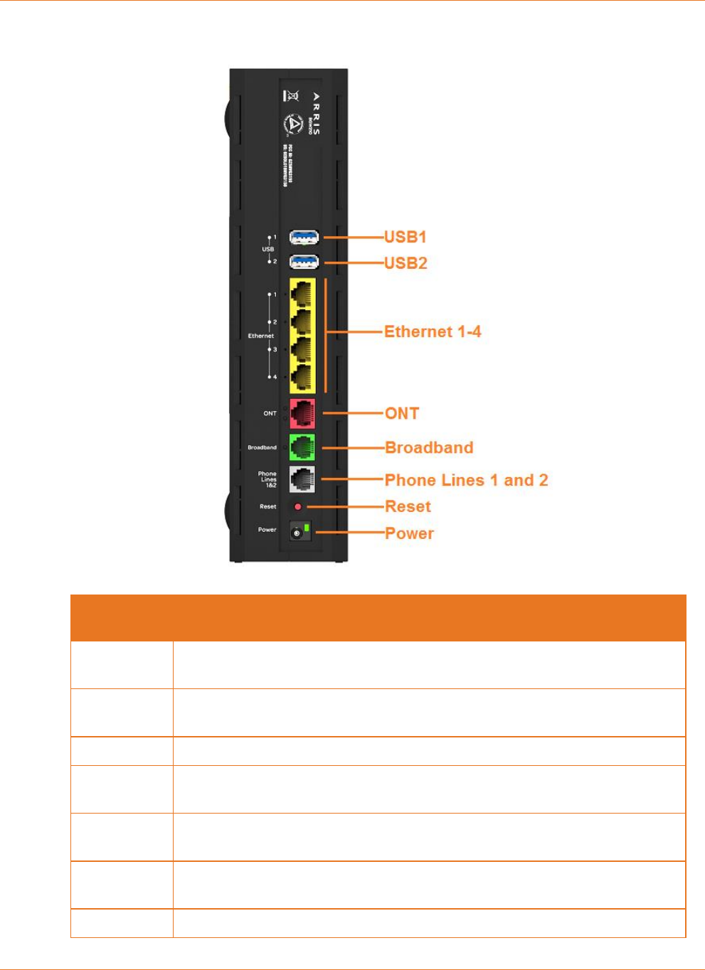
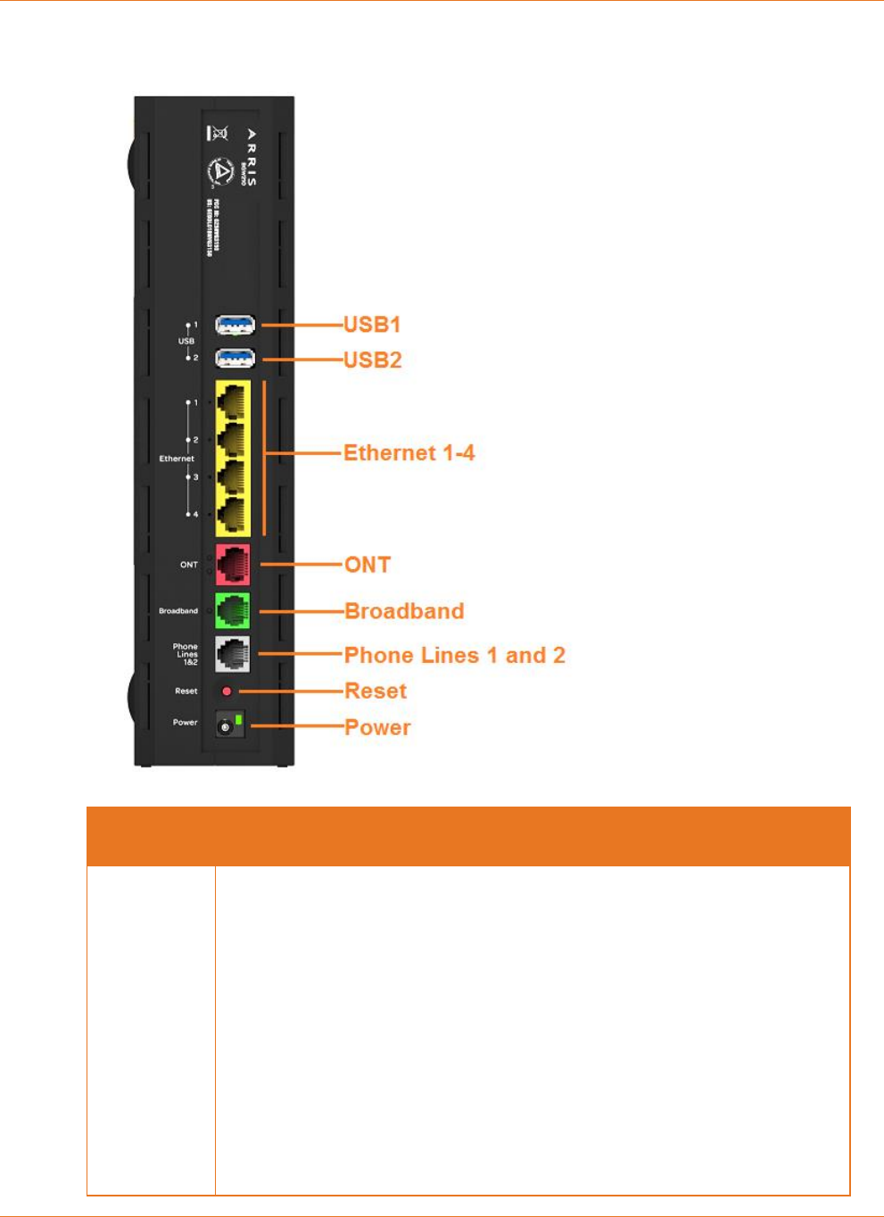
BGW210-700 Broadband Gateway Rear Panel
Port
Description
USB1 and
USB2
Universal Serial Bus connections 1 and 2 for USB devices.
Ethernet
1,2,3,4
Provide connection for up to four Ethernet devices, such as PCs and other
devices.
ONT
The Optical Network Terminal fiber optic connector.
Broadband
An alternate DSL connection to the Internet; its implementation is determined
by the service configuration from the provider.
Phone Lines
1 and 2
Provides connection for up to two VoIP phones. A voice line splitter is
required when connecting two phones.
Reset
Used to reboot the gateway or perform a factory default restore if depressed
for 10 seconds or longer.
Power
Used to power the gateway on/off.

Chapter 3: Hardware Gateway Installation
365-095-30882 Revision 4.0 BGW210-700 Broadband Gateway Release 1.0 Install and Operations Guide
© 2016 ARRIS Enterprises LLC. All Rights Reserved. 11
Connecting the Power Adapter
The power adapter supplies power to the BGW210-700 Broadband Gateway.
1. Connect the appropriate end of the power adapter cable to the BGW210-700 Broadband
Gateway rear panel POWER port.
2. Connect the power plug end to the electrical outlet.
After the BGW210-700 Broadband Gateway is powered on, the power light blinks green
momentarily and then remains steady green.
For all power light indications, see Status Indicator Lights (page 17) under Basic
Troubleshooting.
Warning: Use only the power supply and cord that came with the BGW210-700 Broadband
Gateway. Failure to use the authorized power supply and cord may cause electric shock, fire,
bodily injury, and/or property damage. If the power supply or cord becomes damaged or
needs to be replaced, to obtain an authorized replacement please contact AT&T customer
service by phone (1.800.288.2020) or via website (www.att.com/support).
Connecting Computers to the BGW210-700
Broadband Gateway
The first computer you connect can be used to configure the BGW210-700 Broadband
Gateway settings. You can connect more computers and other devices to the BGW210-700
Broadband Gateway using wireless or wired Ethernet.
Connecting Devices Using Wired Ethernet
The BGW210-700 Broadband Gateway has four wired Ethernet ports that can be used to
connect computers or other devices.
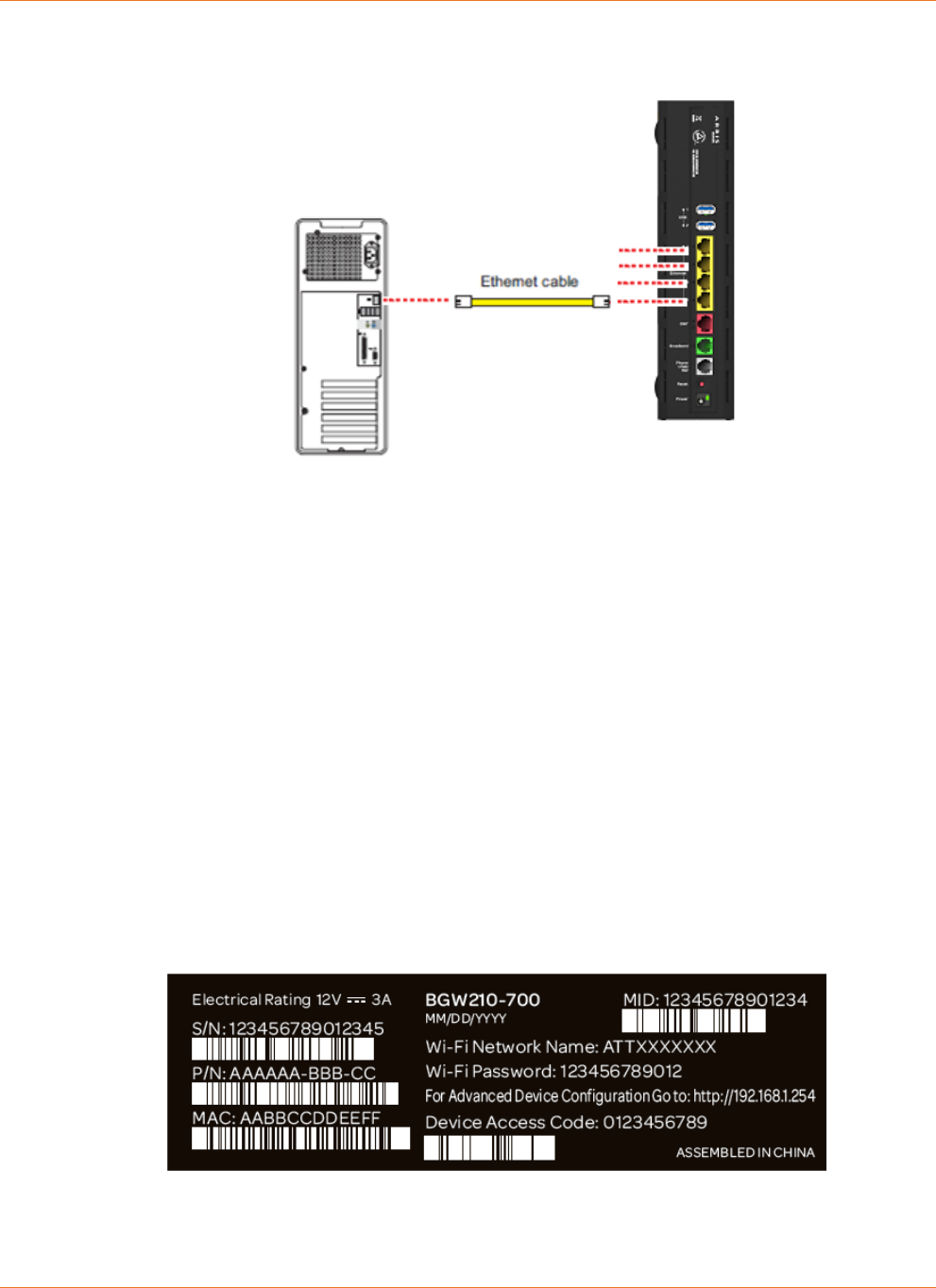
As shown in the illustration below, to connect a computer to the BGW210-700 Broadband
Gateway:
1. Connect one end of the Ethernet cable to one of the Ethernet ports on the BGW210-700
Broadband Gateway.
2. Connect the other end of the cable to the Ethernet port on the computer.
Chapter 3: Hardware Gateway Installation
365-095-30882 Revision 4.0 BGW210-700 Broadband Gateway Release 1.0 Install and Operations Guide
© 2016 ARRIS Enterprises LLC. All Rights Reserved. 12
Connecting a Computer to a Ethernet Port of the BGW210-700 Broadband Gateway
After the gateway recognizes the computer, the Ethernet light turns steady green and blinks
when the computer starts transferring data with the gateway. See Status Indicator Lights
(page 17) under Basic Troubleshooting for all Ethernet light indications.
Connecting Devices Using Wi-Fi
The BGW210-700 Broadband Gateway has an integrated Wi-Fi access point to which you can
use to connect Wi-Fi devices. By default, the BGW210-700 Broadband Gateway is configured
with a Wi-Fi network name (SSID) and is WPA-PSK/WPA2-PSK security enabled.
To connect a Wi-Fi device:
On the Wi-Fi device, view the available Wi-Fi networks. The specifics of how you do this
depend on the device to which you are connecting.
The default Wi-Fi network name (SSID) and the Wi-Fi password (e.g., encryption key) are
printed on the label on the side of the BGW210-700 Broadband Gateway. Select the
appropriate Wi-Fi network name and connect.
BGW210-700 Broadband Gateway Label
At the prompt, enter the Wi-Fi password.
To simplify Wi-Fi device connection to the BGW210-700 Broadband Gateway:
You can configure Wi-Fi Protected Setup (WPS) to the network using the PIN or PUSH method.
Chapter 3: Hardware Gateway Installation
365-095-30882 Revision 4.0 BGW210-700 Broadband Gateway Release 1.0 Install and Operations Guide
© 2016 ARRIS Enterprises LLC. All Rights Reserved. 13
For more information about the PIN method, please see the BGW210-700 Broadband
Gateway AT&T Software Administrator's Handbook, as it describes Web UI access for this
input.
The PUSH method establishes Wi-Fi connectivity if you push the WPS button on the front
panel of the BGW210-700 Broadband Gateway and on the Wi-Fi device.
Upon WPS button push, the WPS button light flashes green until WPS is completed
successfully, at which point it will stay green for 5-minutes (unless pushed again).
See Status Indicator Lights (page 17) under Basic Troubleshooting for all WPS indications.
Connecting the BGW210-700 Broadband Gateway
to the Internet
Note: The appropriate port to connect to the Internet is based on the service configuration
from AT&T. Do not change the port used unless instructed to do so. Only one of these wiring
arrangements can be used at the same time and attempting to use both may interfere with
your service.
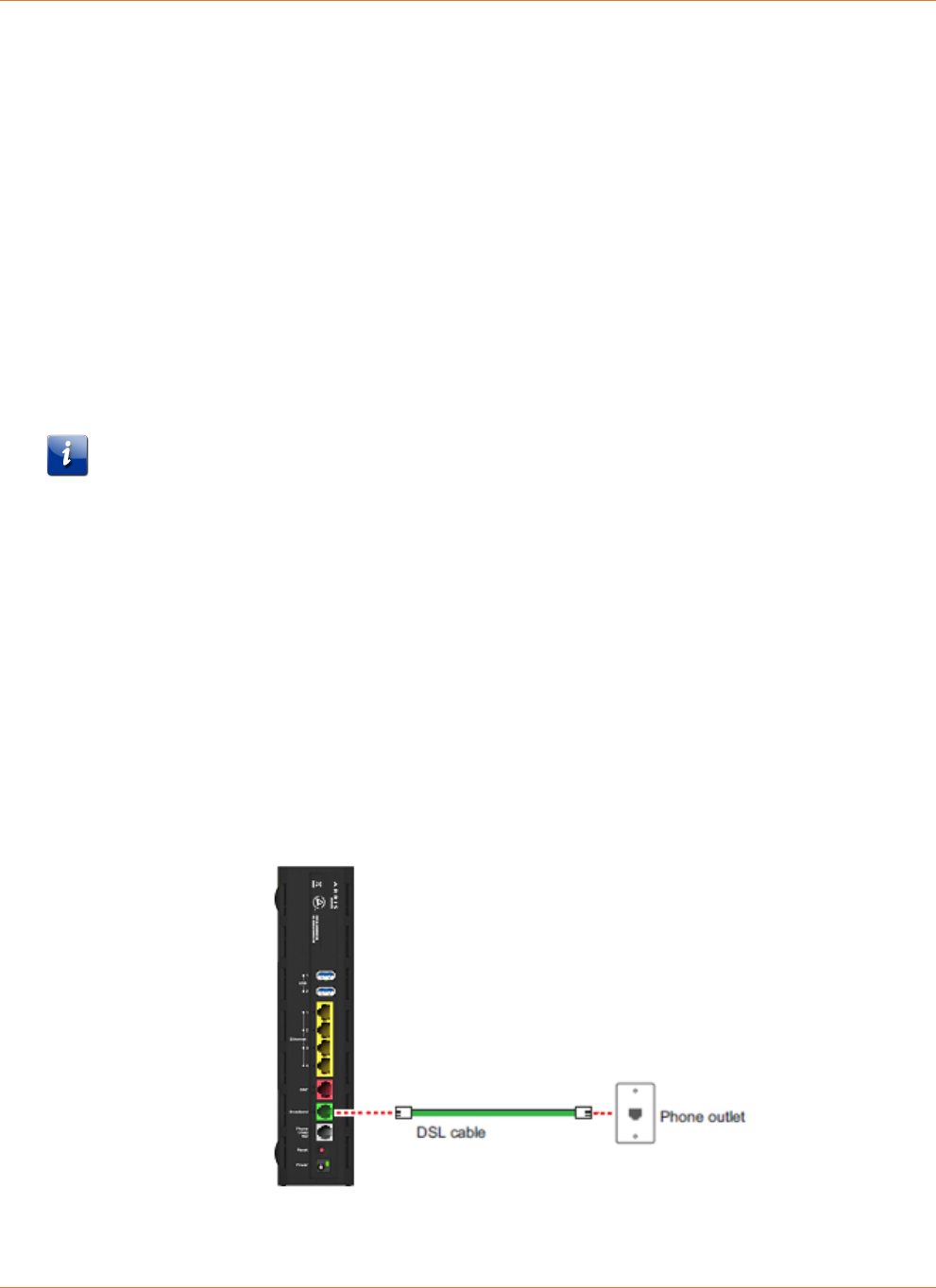
The DSL Broadband port (labeled Broadband) can be used to connect the BGW210-700
Broadband Gateway to the Internet:
1. Connect one end of the DSL cable to the green DSL port on the BGW210-700 Broadband
Gateway.
2. Connect the other end of the DSL cable to the wall outlet.
After the BGW210-700 Broadband Gateway recognizes the connection, the Broadband light
blinks green for a moment and then turns steady green. See Status Indicator Lights (page 17)
under Basic Troubleshooting for all Broadband light indications.
BGW210-700 Broadband Gateway Connection to the Internet

Chapter 3: Hardware Gateway Installation
365-095-30882 Revision 4.0 BGW210-700 Broadband Gateway Release 1.0 Install and Operations Guide
© 2016 ARRIS Enterprises LLC. All Rights Reserved. 14
Alternatively, you can connect the BGW210-700 Broadband Gateway to the Internet using the
WAN Ethernet port (labeled ONT):
1. Connect one end of an Ethernet cable to the WAN Ethernet port on the BGW210-700
Broadband Gateway.
2. Connect the other end of the cable to the operator provided WAN Ethernet jack or ONT.
After the BGW210-700 Broadband Gateway recognizes the connection, the Broadband light
blinks green for a moment and then turns steady green. See Status Indicator Lights (page 17)
under Basic Troubleshooting for all Broadband light indications.
Connecting VoIP Telephones
The BGW210-700 Broadband Gateway includes one RJ-14 port (labeled Phone 1 & 2) with the
capacity to support two phone lines using a splitter or multi-jack adapter.
Note: The BGW210-700 Broadband Gateway supports two VoIP lines over
one RJ14 (FXS) VoIP port. To connect two phone lines, an inner and outer
pair splitter adapter must be attached to the RJ14 (FXS) VoIP port to
terminate both lines.
Warning: Do not connect the VoIP lines to your current home telephone wiring, especially if
your home has an alarm system. Ensure that you are subscribed to VoIP service for this
interface to be used.
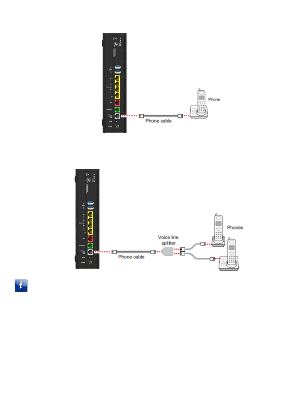
As shown in the figures below, to connect phones directly to your gateway:
1. Connect one end of the phone cable to the gray Phone Lines 1&2 connector on the
BGW210-700 Broadband Gateway.
2. To connect to the telephone(s), do one of the following:
For one phone, connect the phone cable directly to the telephone.
Chapter 3: Hardware Gateway Installation
365-095-30882 Revision 4.0 BGW210-700 Broadband Gateway Release 1.0 Install and Operations Guide
© 2016 ARRIS Enterprises LLC. All Rights Reserved. 15
Single Phone Connection
For two phones, connect the phone cable to a splitter and then to the phones.
Two Phone Connection Using Splitter
Note: To prevent interference with cordless phones, ensure that the BGW210-700 Broadband
Gateway is at least 5 feet (1.5 m) from any cordless phone base station.
After the gateway recognizes the phones (Line 1 and Line 2), the Phone 1 & Phone 2 lights
turn steady green and blink when the associated phone is in use. See Status Indicator Lights
(page 17) under Basic Troubleshooting for all Phone light indications.

365-095-30882 Revision 4.0 BGW210-700 Broadband Gateway Release 1.0 Install and Operations Guide
© 2016 ARRIS Enterprises LLC. All Rights Reserved. 16
Chapter 4
Basic Troubleshooting
This chapter provides simple troubleshooting suggestions for issues with the initial
configuration of the BGW210-700 Broadband Gateway. The following topics are covered:
Status Indicator Lights (page 17)
Rear Panel Connectors (page 23)
Factory Reset Switch (page 24)
Before troubleshooting:
Read this guide, including Hardware Gateway Installation (page 9) and all of the subtopics.
Set the TCP/IP controls on the PC to obtain an IP address automatically.
For additional troubleshooting support please see BGW210-700 Broadband Gateway
AT&T Software Administrator's Handbook, which addresses product Web UI and CLI
information.
Chapter 4: Basic Troubleshooting
365-095-30882 Revision 4.0 BGW210-700 Broadband Gateway Release 1.0 Install and Operations Guide
© 2016 ARRIS Enterprises LLC. All Rights Reserved. 17
Status Indicator Lights
Check the status indicator lights (LEDs) to begin troubleshooting. Use the front and rear view
graphics that follow, as well as the LED Activity descriptions table to interpret the LED
indicators.
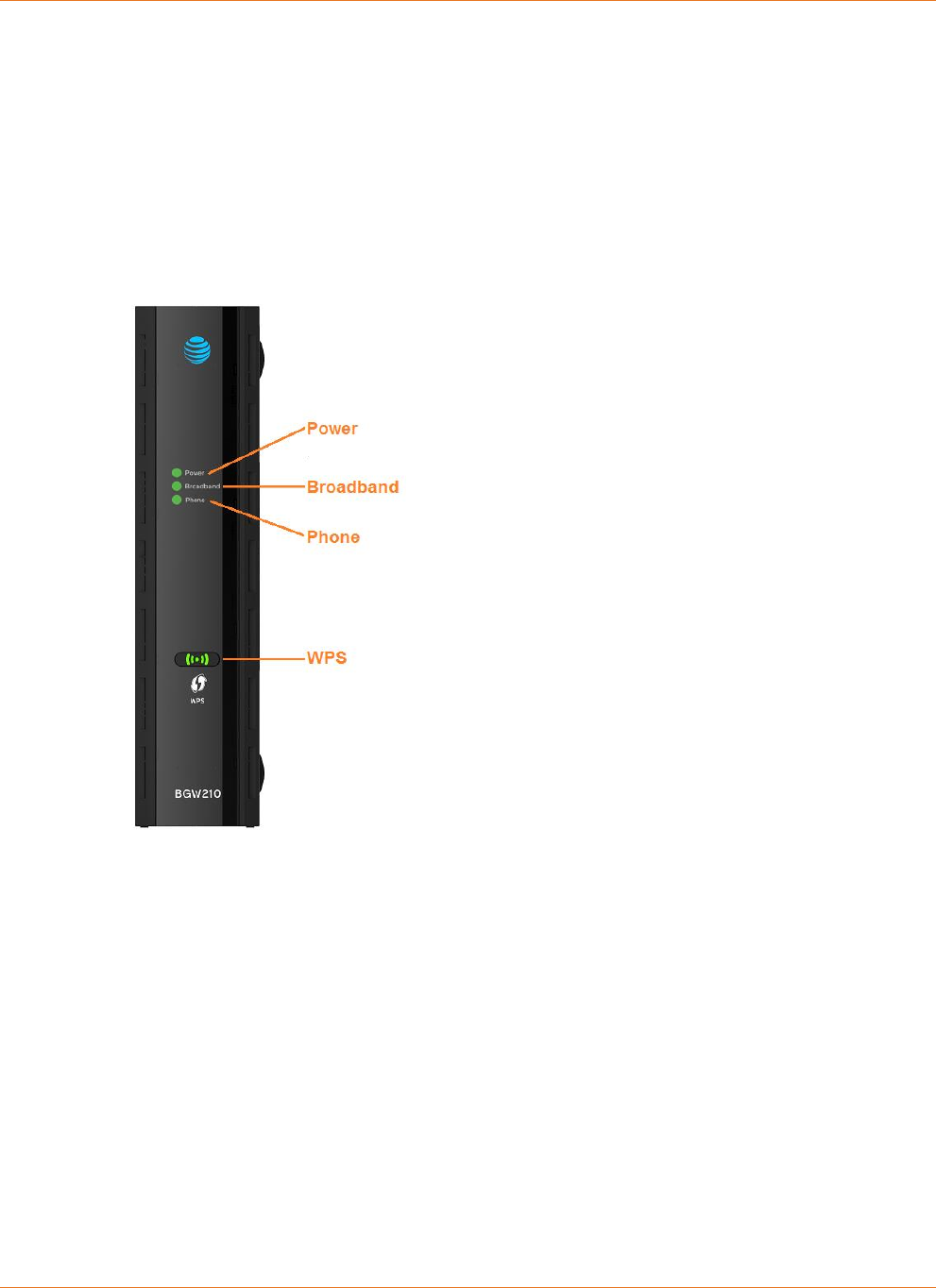
BGW210-700 Broadband Gateway Status Indicator Lights
Front View
Chapter 4: Basic Troubleshooting
365-095-30882 Revision 4.0 BGW210-700 Broadband Gateway Release 1.0 Install and Operations Guide
© 2016 ARRIS Enterprises LLC. All Rights Reserved. 18
Rear View
LED
Activity
All LEDs
During Boot
Process
If the BGW210-700 Broadband Gateway boots and does not detect a
failure:
The Power, Broadband, and Phone LEDs all Flash Green, Power LED
goes Solid Green and all other LEDs are Off. Power LED starts Flashing
Green during Power On Self Test (POST), Power LED goes Solid Green
and all other LEDs start functioning with normal behavior.
If the BGW210-700 Broadband Gateway does not boot and fails its self-
test or fails to perform initial load of the bootloader:
All LEDs on the front of the device continuously flash red in unison.
If the BGW210-700 Broadband Gateway boots and then detects a failure:
Power, Broadband, and Phone LEDs all Flash Green for 2 to 3 seconds,
and then all LEDs will flash red, including Power LED.

Chapter 4: Basic Troubleshooting
365-095-30882 Revision 4.0 BGW210-700 Broadband Gateway Release 1.0 Install and Operations Guide
© 2016 ARRIS Enterprises LLC. All Rights Reserved. 19
LED
Activity
Power
(Front Panel)
Solid Green = The device is powered.
Off = The unit has no AC power.
Flashing Green = The POST is in progress. Also flashes green during initial
power-up of the device.
Flashing Red = A POST failure (not bootable) or device malfunction
occurred.
Note: A malfunction is defined as any error of internal sequence or
state (not network connectivity) that prevents the BGW210-700
Broadband Gateway from connecting to the broadband network or
passing data. This may be identified at various times such as after
power-on or during operation through the use of self testing or in
operations, which result in a unit state that is not expected or should
not occur.
Power LED
During a
Software
Upgrade
During the software installation you will lose Internet and phone service.
The LEDs will function as follows:
1. As software is being loaded into flash, the LEDs operate normally.
2. During the software upgrade, which takes about 12 seconds, the
Power LED will flash Orange (flash writing to memory), and all
other LEDs operate normally.
3. The BGW210-700 Broadband Gateway restarts automatically. As
the BGW210-700 Broadband Gateway reboots, the LEDs display
power-on behavior.

Chapter 4: Basic Troubleshooting
365-095-30882 Revision 4.0 BGW210-700 Broadband Gateway Release 1.0 Install and Operations Guide
© 2016 ARRIS Enterprises LLC. All Rights Reserved. 20
LED
Activity
Broadband
WAN
(Front Panel)
Solid Green = Good broadband connection (good sync for a DSL line or
signal detected for other types of broadband connections). Only
displays when not in alert mode.
Off = The device is not powered. When in alert mode, the Solid Green
and Flashing Green indications will not be displayed and the LED will
be off. The alert mode is intended to avoid showing broadband WAN
and VoIP LEDs unless there is an issue. By default the alert mode is
disabled.
Flashing Green = Attempting broadband connection (e.g., DSL
attempting sync, attempting 802.1x or attempting to obtain DHCP
information). Only displays when not in alert mode. Also flashes green
during initial power-up of the device.
Flashing Yellow = LTE device is in place, but not operating properly
when a primary connection is working.
Flashing Red = A broadband signal is detected, but the connection
could not be fully established or the device attempted to become IP
connected and failed.
Solid Red = No signal on a line and the line is configured to be used
(including when there is no signal on one pair of a bonded-pair
connection as identified through manual or G.997.1 communication).
The LED will light only when there is no signal, not during times of
temporary no tone during the training sequence or when attempting
to establish a connection.
During a software upgrade the LED will continue to function properly
and not have any specialized sequence.
Off = The device is not powered.
Phone
(Front Panel)
Solid Green = At least one VoIP line has been configured and all
configured VoIP lines are registered with a SIP proxy server. Only
displays when not in alert mode.
Flashing Green = Indicates ringing associated with an incoming call, as
well as when a telephone is off-hook, on either FXS port. Only displays
when not in alert mode. Also flashes green during initial power-up of
the device.
Solid Red = One or more configured lines are not registered with a SIP
proxy server.
Off = VoIP not in use (e.g. both VoIP lines are not configured) or
BGW210-700 Broadband Gateway power is off. When in alert mode
the Solid Green and Flashing Green will not be displayed and the LED
will be off.
During a software upgrade the LED will continue to function properly
and not have any specialized sequence.

Chapter 4: Basic Troubleshooting
365-095-30882 Revision 4.0 BGW210-700 Broadband Gateway Release 1.0 Install and Operations Guide
© 2016 ARRIS Enterprises LLC. All Rights Reserved. 21
LED
Activity
WPS (appears
After Using
WPS button)
Solid Green = Wi-Fi Protected Setup has been completed successfully.
LED should stay on for 5 minutes or until push button is pressed again.
Flashing Green = Continues for 2 minutes, indicating when WPS is
broadcasting.
Flashing Red = Continues for 2 minutes, indicating a Session overlap
was detected (possible security risk).
Solid Red = Error unrelated to security, such as failure to find a
partner, or WPS is disabled. LED should stay solid red for 5 minutes or
until push button is pressed again.
Off = The gateway is ready for WPS authentication.
Ethernet
1,2,3,4
(Rear Panel)
Solid Green = A 10/100/1000 Ethernet device is connected.
Off = The BGW210-700 Broadband Gateway is not powered or no
powered devices are connected to the associated ports.
Power Jack
(Rear Panel)
Green = The voltage present at the DC input connector is equal to or
above the required minimum specification of 11.4 volts.
Off = The voltage present at the DC input connector is below the
required minimum specification of 10.8 volts.
Problem Isolation
If a status indicator light does not look correct, look for these possible problems:
LED Not Lit
Possible Problems
Power
(Front Panel)
Check the rear panel Power LED, which is to the right of the connector for
the cord from the power adapter.
If the rear panel Power LED is on, contact AT&T by phone
(1.800.288.2020) or via website (www.att.com/support).
If the rear panel Power LED is off:
o Make sure the power adapter is plugged into the gateway properly.
For location, see Rear Panel Connectors (page 23).
o Try a known good wall outlet.
o If a power strip is used, make sure it is switched on.

Chapter 4: Basic Troubleshooting
365-095-30882 Revision 4.0 BGW210-700 Broadband Gateway Release 1.0 Install and Operations Guide
© 2016 ARRIS Enterprises LLC. All Rights Reserved. 22
LED Not Lit
Possible Problems
Broadband
Make sure that you are using the correct cable. The DSL cable is a thinner
standard telephone cable and is labeled Data Cable.
Make sure the DSL cable is plugged into the correct wall jack.
Make sure the DSL cable is plugged into the DSL port on the DSL gateway.
Make sure the DSL line has been activated by AT&T.
Make sure the DSL gateway is not plugged into a micro-filter.
Check if any telephone directly connected to a home wall phone jack (not
to the gateway's phone port) has a micro-filter installed. If not, it may need
to be installed, assuming the home does not use a DSL splitter to separate
home phone and DSL lines.
Ethernet
1,2,3,4
(Rear Panel)
Make sure that you are using the yellow Ethernet cable, not the DSL cable.
The Ethernet cable is thicker than a standard telephone cable.
Make sure the Ethernet cable is securely plugged into the Ethernet jack on
the PC.
Make sure the Ethernet cable is securely plugged into the Ethernet port on
the DSL gateway.
Make sure you have Ethernet drivers installed on the PC.
Make sure the PC’s TCP/IP properties for the Ethernet network control
panel are set to obtain an IP address via DHCP.
Make sure the PC has obtained an address in the 192.168.1.x range. (You
may have changed the subnet addressing.)
Make sure the PC is configured to access the Internet over a LAN.
Disable any installed network devices (Ethernet, HomePNA, Wi-Fi) that are
not being used to connect to the DSL gateway.
Chapter 4: Basic Troubleshooting
365-095-30882 Revision 4.0 BGW210-700 Broadband Gateway Release 1.0 Install and Operations Guide
© 2016 ARRIS Enterprises LLC. All Rights Reserved. 23
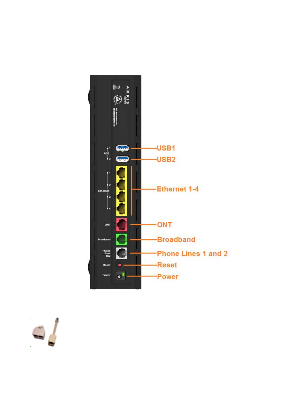
Rear Panel Connectors
Connectors on the rear panel are depicted below.
BGW210-700 Broadband Gateway Rear Panel
Note: The BGW210-700 Broadband Gateway supports two VoIP lines over
one RJ14 (FXS) VoIP port. To connect two phone lines, an inner and outer
pair splitter adapter must be attached to the RJ14 (FXS) VoIP port to
terminate both lines.
Chapter 4: Basic Troubleshooting
365-095-30882 Revision 4.0 BGW210-700 Broadband Gateway Release 1.0 Install and Operations Guide
© 2016 ARRIS Enterprises LLC. All Rights Reserved. 24
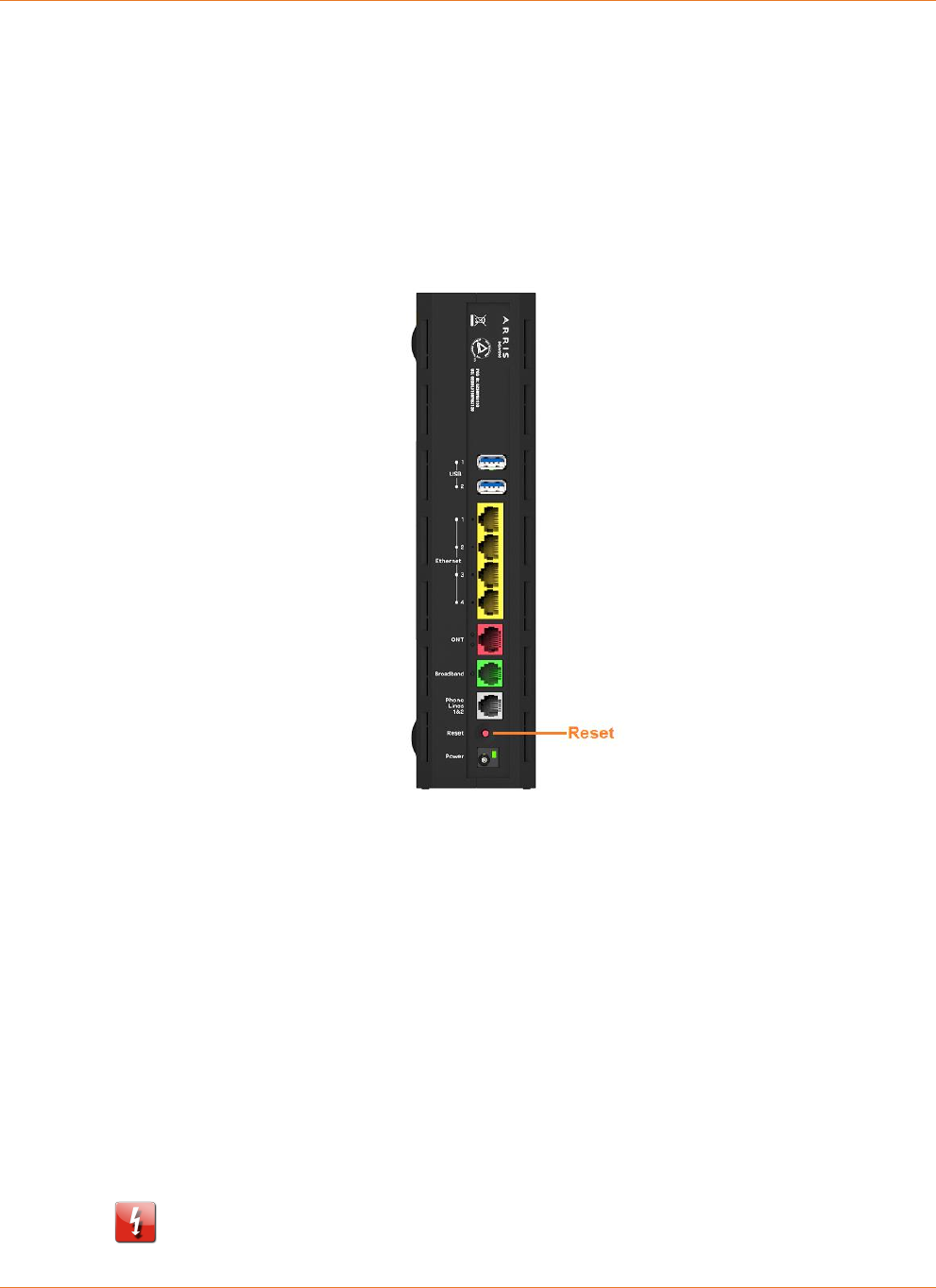
Factory Reset Switch
The Reset switch will result in a reboot of the BGW210-700 Broadband Gateway. Depending
on the software loaded on the BGW210-700 Broadband Gateway, holding it for an elongated
duration of time may reset the device to factory defaults.
Referring to the diagram below, find the round Reset switch opening.
BGW210-700 Broadband Gateway Reset Switch Location
Press the reset button to initiate the following:
Press the factory reset button for less than ten seconds to reboot the BGW210-700
Broadband Gateway, the indicator lights on the device will respond immediately and
start blinking red within one second of the reset button being pressed.
The lights will blink whether the button is still being pressed or has been released. The
indicator lights will flash for a minimum of five seconds, even if the reset button is
released within five seconds of being pressed. If the reset button is held for more than
five seconds, it will continue to blink until released or until ten seconds have elapsed
(see below).
Press the factory reset button and hold for longer than ten seconds, to reset the
device to the factory default shipped settings. If the button is held for ten seconds, the
Power indicator continues to blink for an additional five seconds, and then the
indicator lights return to their normal operating mode, whether or not the reset
button is still depressed.
Warning: Resetting the BGW210-700 Broadband Gateway to factory defaults will
require all configured settings to be reconfigured.

Chapter 5: Technical Specifications and Safety Information
365-095-30882 Revision 4.0 BGW210-700 Broadband Gateway Release 1.0 Install and Operations Guide
© 2016 ARRIS Enterprises LLC. All Rights Reserved. 25
Chapter 5
Technical Specifications and Safety
Information
Dimensions and Interfaces
Dimensions and Interfaces
Dimensions/Weight/Placement
Dimensions - 9.8in. High x 7.9in. Deep x 2.36in. Wide
(249mm High x 201mm Deep x 60mm Wide)
Weight - 1.9 lbs (0.882 kg)
Placement - Vertical desktop or vertical wall mount
Communications interfaces
Concurrent Wi-Fi support for 400 mW
802.11b/g/n and 802.11ac
Four-port 10/100/1000Base-T Ethernet switch, RJ-45
Single-port voice FXS, RJ-14
Two-port USB 2.0
WAN Interfaces
Bonded VDSL2/single line VDSL2/bonded
ADSL2+/single line ADSL, RJ-14
One-port 10/100/1000 Ethernet, RJ-45
Concurrent Wi-Fi
802.11 b/g/n and 802.11ac 400 mW high-power
radio
Wi-Fi Characteristics
2.4GHz support, 3x3 integrated omni-directional
antenna with diversity
5GHz support, 4x4

Chapter 5: Technical Specifications and Safety Information
365-095-30882 Revision 4.0 BGW210-700 Broadband Gateway Release 1.0 Install and Operations Guide
© 2016 ARRIS Enterprises LLC. All Rights Reserved. 26
Power Supply
This product is intended to be supplied with a Listed Direct Plug-In AC/DC power adapter
marked Class 2 LPS power supply rated @ 12V 3A DC for all BGW210-xxx models.
The AC/DC power adapter supplied with this product is designed to ensure your personal
safety and to be compatible with this equipment. Use only the power adapter that was
provided with the gateway.
Environment
Operating temperature: 0°C to 41.7°C (32° F to 107° F); 8% to 95% (Non Condensing) Relative
Humidity
Storage temperature: –40° C to 80° C (–40° F to 176° F)
Agency Approvals
North America
Safety Approvals:
United States – UL 60950, Third Edition
EMC:
United States – FCC Part 15 Class B, Subparts B, C, and E
Telecom:
United States – CFR Part 68
Caring for the Environment by Recycling
When you see this symbol on an
ARRIS product, do not dispose of the
product with residential or
commercial waste.
Recycling your ARRIS Equipment
Please do not dispose of this product with
your residential or commercial waste.
Some countries or regions have set up
systems to collect and recycle electrical
and electronic waste items. Contact your
local authorities for information about
practices established for your region. If
collection systems are not available,
contact ARRIS Customer Service for
assistance at www.arris.com/consumers.

Chapter 6: Important Safety Instructions
365-095-30882 Revision 4.0 BGW210-700 Broadband Gateway Release 1.0 Install and Operations Guide
© 2016 ARRIS Enterprises LLC. All Rights Reserved. 27
Chapter 6
Important Safety Instructions
Warning: Do not use before reading these instructions.
Do not connect the Broadband Ethernet port (labeled ONT) to a carrier or carriage service
provider’s telecommunications network or facility unless:
A) You have the written consent of the network or facility manager, or
B) The connection is in accordance with a connection permit or connection rules.
Connection of the Ethernet ports may cause a hazard or damage to the telecommunication
network or facility, or persons, with consequential liability for substantial compensation.
WARNINGS
The power supply must be connected to an outlet. Do not defeat the protective earth
connection. The direct plug-in power supply serves as the main power disconnect; locate the
direct plug-in power supply near the product for easy access.
Product Ventilation
The gateway is intended for residential use. Position the gateway in an upright vertical
position and locate it where temperatures remain within a range of 32° – 107°F (0° – 41.7°C)
and where heat from the unit itself is not trapped. There must be at least two inches (2") of
clearance on all sides except the bottom.
Telecommunication Installation Cautions
Never install telephone wiring during a lightning storm.
Never install telephone jacks in wet locations unless the jack is specifically designed for
wet locations.
Never touch uninsulated telephone wires or terminals unless the telephone line has been
disconnected at the network interface.
Use caution when installing or modifying telephone lines.
Avoid using a telephone (other than a cordless type) during an electrical storm. There may
be a remote risk of electric shock from lightning.

Chapter 6: Important Safety Instructions
365-095-30882 Revision 4.0 BGW210-700 Broadband Gateway Release 1.0 Install and Operations Guide
© 2016 ARRIS Enterprises LLC. All Rights Reserved. 28
Do not use the telephone to report a gas leak in the vicinity of the leak.
Electrical Safety Advisory
Telephone companies report that electrical surges, typically lightning transients, are very
destructive to customer terminal equipment connected to AC power sources. This has been
identified as a major nationwide problem. Therefore it is advised that this equipment be
connected to AC power through the use of a surge arrestor or similar protection device.
Declaration of Conformance
Warning: This is a Class B product. In a domestic environment this product may cause radio
interference, in which case the user may be required to take adequate measures. Adequate
measures include increasing the physical distance between this product and other electrical
devices. Changes or modifications to this unit not expressly approved by the party responsible
for compliance could void the user’s authority to operate the equipment.
United States: This device complies with Part 15 of the FCC Rules. Operation is subject to the
following two conditions:
1. This device may not cause harmful interference, and
2. This device must accept any interference received, including interference that may cause
undesired operation.
This equipment has been tested and found to comply with the limits for a Class B digital
device, pursuant to Part 15 of the FCC Rules. These limits are designed to provide reasonable
protection against harmful interference in a residential installation. This equipment generates,
uses, and can radiate radio frequency energy and, if not installed and used in accordance with
the instructions, may cause harmful interference to radio communications. However, there is
no guarantee that interference will not occur in a particular installation. If this equipment
does cause harmful interference to radio or television reception, which can be determined by
turning the equipment off and on, the user is encouraged to try to correct the interference by
one or more of the following measures:
Reorient or relocate the receiving antenna.
Increase the separation between the equipment and receiver.
Connect the equipment into an outlet on a circuit different from that to which the receiver
is connected.
Consult the dealer or an experienced radio/TV technician for help.
47 CFR Part 68 Information
United States: This device complies with 47 CFR Part 68 of the FCC Rules. Operation is subject
to the following four conditions:

Chapter 6: Important Safety Instructions
365-095-30882 Revision 4.0 BGW210-700 Broadband Gateway Release 1.0 Install and Operations Guide
© 2016 ARRIS Enterprises LLC. All Rights Reserved. 29
1. The Federal Communications Commission (FCC) has established Rules, which permit this
device to be directly connected to the telephone network. Standardized jacks are used for
these connections. This equipment should not be used on party lines or coin phones.
2. If this device is malfunctioning, it may also be causing harm to the telephone network; this
device should be disconnected until the source of the problem can be determined and
until repair has been made. If this is not done, the telephone company may temporarily
disconnect service.
3. The telephone company may make changes in its technical operations and procedures; if
such changes affect the compatibility or use of this device, the telephone company is
required to give adequate notice of the changes. You will be advised of your right to file a
complaint with the FCC.
4. If the telephone company requests information on what equipment is connected to their
lines, inform them of:
The telephone number to which this unit is connected.
The ringer equivalence number. [0.XB] (Indicated on the label)
The USOC jack required. [RJ11C]
The FCC Registration Number. [US:AAAEQ##TXXXX] (Indicated on the label)
The Ringer Equivalence Number (REN) is used to determine how many devices can be
connected to your telephone line. In most areas, the sum of the REN's of all devices on
any one line should not exceed five (5.0). If too many devices are attached, they may
not ring properly.
FCC Caution
Caution: Any changes or modifications not expressly approved by the party responsible for
compliance could void the user’s authority to operate this equipment. This transmitter must
not be co-located or operating in conjunction with any other antenna or transmitter.
Radiation Exposure Statement
This equipment complies with FCC radiation exposure limits as set forth for an uncontrolled
environment. This equipment should be installed and operated maintaining a minimum
distance of 22 cm (9 inches) between the device and your body.

Chapter 6: Important Safety Instructions
365-095-30882 Revision 4.0 BGW210-700 Broadband Gateway Release 1.0 Install and Operations Guide
© 2016 ARRIS Enterprises LLC. All Rights Reserved. 30
Service Requirements
In the event of equipment malfunction, if under warranty, we will exchange a product
deemed defective. Under FCC rules, no customer is authorized to repair this equipment. This
restriction applies regardless of whether the equipment is in or out of warranty.
Technical Support for Hardware Products:
Customers inside North America: 888-944-4357 (888-944-HELP)
Customers outside North America: 1-215-323-2345
For Spanish language support: 1-215-323-2346
Note: This product was tested for FCC compliance under conditions that included the use of
shielded cables and connectors between system components. Changes or modifications to
this product not authorized by the manufacturer could void your authority to operate the
equipment.

Chapter 7: ARRIS Contacts
365-095-30882 Revision 4.0 BGW210-700 Broadband Gateway Release 1.0 Install and Operations Guide
© 2016 ARRIS Enterprises LLC. All Rights Reserved. 31
Chapter 7
ARRIS Contacts
Technical Services
For technical support on ARRIS products you can contact us by phone or on the web.
By Telephone
The Technical Assistance Center can be reached at:
1-888-944-HELP (4357)
On the Web
The Ask ARRIS web site gives you web access to service and support tools.
You will need to register using your support contract ID and email address.
Ask ARRIS is located at:
http://www.arris.com/support
There you will be able to access:
Support Contact Information for all products
Knowledge Base Information (also known as Solutions)
User Documentation
Current open support cases
Ability to create a new support case (for technical support or repair and
return)
Training Webcast
By Email
Email addresses for ARRIS products will be provided with your account at Ask
ARRIS.
Technical Training
For more information about our Global Knowledge Services Department and the programs we
offer, e-mail us at:
training@arris.com

Corporate Headquarters
ARRIS · Suwanee · Georgia · 30024 · USA
T: 1-678-473-2000 F: 1-678-473-8470
www.arris.com