ARRIS HH1620 DSL VoIP Wireless Gateway User Manual
ARRIS Group, Inc. DSL VoIP Wireless Gateway
ARRIS >
User Manual
User Guide
HH1620
Wireless VoIP Gateway

Important Safety Information
WARNING: TO PREVENT FIRE OR SHOCK HAZARD, DO NOT EXPOSE THIS PRODUCT TO RAIN
OR MOISTURE. THE UNIT MUST NOT BE EXPOSED TO DRIPPING OR SPLASHING. DO NOT
PLACE OBJECTS FILLED WITH LIQUIDS, SUCH AS VASES, ON THE UNIT.
CAUTION: TO PREVENT ELECTRIC SHOCK, THIS EQUIPMENT MAY REQUIRE A GROUNDING
CONDUCTOR IN THE LINE CORD. CONNECT THE UNIT TO A GROUNDING TYPE AC WALL
OUTLET USING THE POWER CORD SUPPLIED WITH THE UNIT.
CAUTION: THIS PRODUCT WAS QUALIFIED UNDER TEST CONDITIONS THAT INCLUDED THE
USE OF THE SUPPLIED CABLES BETWEEN SYSTEMS COMPONENTS. TO ENSURE
REGULATORY AND SAFETY COMPLIANCE, USE ONLY THE PROVIDED POWER AND INTERFACE
CABLES AND INSTALL THEM PROPERLY.
CAUTION: DIFFERENT TYPES OF CORD SETS MAY BE USED FOR CONNECTIONS TO THE MAIN
SUPPLY CIRCUIT. USE ONLY A MAIN LINE CORD THAT COMPLIES WITH ALL APPLICABLE
PRODUCT SAFETY REQUIREMENTS OF THE COUNTRY OF USE.
CAUTION: INSTALLATION OF THIS PRODUCT MUST BE IN ACCORDANCE WITH NATIONAL
WIRING CODES AND CONFORM TO LOCAL REGULATIONS.
CAUTION: DO NOT OPEN THE UNIT. DO NOT PERFORM ANY SERVICING OTHER THAN THAT
CONTAINED IN THE INSTALLATION AND TROUBLESHOOTING INSTRUCTIONS. REFER ALL
SERVICING TO QUALIFIED SERVICE PERSONNEL.
CAUTION: CHANGES AND MODIFICATIONS NOT EXPRESSLY APPROVED BY MOTOROLA FOR
COMPLIANCE COULD VOID USER’S AUTHORITY TO OPERATE THE EQUIPMENT.
i

IMPORTANT SAFETY INSTRUCTIONS — When using your telephone equipment, basic safety
precautions should always be followed to reduce the risk of fire, electric shock, and injury to persons,
including the following:
Read all of the instructions listed here and/or in the user manual before you operate this
equipment. Give particular attention to all safety precautions. Retain the instructions for future
reference.
This device must be installed and used in strict accordance with manufacturer’s instructions as
described in the user documentation that comes with the product.
Comply with all warning and caution statements in the instructions. Observe all warning and
caution symbols that are affixed to this equipment.
Comply with all instructions that accompany this equipment.
Do not overload outlets or extension cords, as this can result in a risk of fire or electric shock.
Overloaded AC outlets, extension cords, frayed power cords, damaged or cracked wire insulation,
and broken plugs are dangerous. They may result in a shock or fire hazard.
Route power supply cords so that they are not likely to be walked on or pinched by items placed
upon or against them. Pay particular attention to cords where they are attached to plugs and
convenience receptacles, and examine the point where they exit from the product.
Place this equipment in a location that is close enough to an electrical outlet to accommodate the
length of the power cord.
Place unit to allow for easy access when disconnecting the power cord of the device from the AC
wall outlet.
Do not connect the plug into an extension cord, receptacle, other outlet unless the plug can be
fully inserted with no part of the blades exposed.
Place this equipment on a stable surface.
It is recommended that the customer install an AC surge protector in the AC outlet to which this
device is connected. This is to avoid damaging the equipment by local lightning strikes and other
electrical surges.
Do not cover the device, or block the airflow to the device with any other objects. Keep the device
away from excessive heat and humidity and keep the device free from vibration and dust.
Wipe the unit with a clean, dry cloth. Never use cleaning fluid or similar chemicals. Do not spray
cleaners directly on the unit or use forced air to remove dust.
Operate this product only from the type of power source indicated on the product’s marking label.
If you are not sure of the type of power supplied to your home, consult your dealer or local power
company.
Do not use this product near water for example, near a bathtub, washbowl, kitchen sink or laundry
tub, in a wet basement or near a swimming pool.
Avoid using a telephone (other than a cordless type) during an electrical storm. There may be a
remote risk of electric shock from lightning.
Do not use the telephone to report a gas leak in the vicinity of the leak.
Use only the power cord and batteries indicated in this manual. Do not dispose of batteries in a
fire. They may explode. Check with local codes for possible special disposal instructions.
CAUTION: To reduce the risk of fire, use only No. 26 AWG or larger (e.g., 24 AWG) UL Listed or
CSA Certified Telecommunication Line Cord.
Disconnect TNV circuit connector(s) before disconnecting power.
Disconnect TNV circuit connector before removing cover.
Upon completion of any service or repairs to this product, ask the service technician to perform
safety checks to determine that the product is in safe operating condition.
SAVE THESE INSTRUCTIONS
ii

FCC Compliance Class B Digital Device
This equipment has been tested and found to comply with the limits for a Class B digital
device, pursuant to Part 15 of the FCC Rules. These limits are designed to provide
reasonable protection against harmful interference in a residential environment. This
equipment generates, uses, and can radiate radio frequency energy and, if not installed and
used in accordance with the instructions, may cause harmful interference to radio
communications. However, there is no guarantee that interference will not occur in a
particular installation. If this equipment does cause harmful interference to radio or television
reception, which can be determined by turning the equipment off and on, the user is
encouraged to try to correct the interference by one of the following measures:
Reorient or relocate the receiving antenna.
Increase the separation between the equipment and receiver.
Connect the equipment into an outlet on a circuit different from that to which the receiver
is connected.
Consult the dealer or an experienced radio/TV technician for help.
CAUTION: Changes or modifications not expressly approved by Motorola for compliance
could void the user’s authority to operate the equipment.
Canadian Compliance
This Class B digital apparatus meets all requirements of the Canadian Interference Causing
Equipment Regulations. Cet appareil numérique de la classe B respects toutes les exigences
du Règlement sur le matériel brouilleur du Canada.
Wireless LAN Information
The HH1620 Wireless VoIP products are wireless network products that use Direct Sequence
Spread Spectrum (DSSS) radio technology. These products are designed to be inter-operable
with any other wireless DSSS type product that complies with:
Wireless LAN and your Health
The HH1620, like other radio devices, emit radio frequency electromagnetic energy, but
operate within the guidelines found in radio frequency safety standards and recommendations.
Restrictions on Use of Wireless Devices
In some situations or environments, the use of wireless devices may be restricted by the
proprietor of the building or responsible representatives of the organization. For example,
using wireless equipment in any environment where the risk of interference to other devices
or services is perceived or identified as harmful.
If you are uncertain of the applicable policy for the use of wireless equipment in a specific
organization or environment, you are encouraged to ask for authorization to use the device
prior to turning on the equipment.
The manufacturer is not responsible for any radio or television interference caused by
unauthorized modification of the devices included with this product, or the substitution or
attachment of connecting cables and equipment other than specified by the manufacturer.
Correction of interference caused by such unauthorized modification, substitution, or
attachment is the responsibility of the user.
The manufacturer and its authorized resellers or distributors are not liable for any damage or
violation of government regulations that may arise from failing to comply with these guidelines.
FCC Certification
The HH1620 contain a radio transmitter and accordingly have been certified as compliant with
47 CFR Part 15 of the FCC Rules for intentional radiators. Products that contain a radio
transmitter are labeled with FCC ID and the FCC logo.
Caution: Exposure to Radio Frequency Radiation.
To comply with the FCC RF exposure compliance requirements, the separation distance
between the antenna and any person’s body (including hands, wrists, feet and ankles) must
be at least 20 cm (8 inches).
iii

Canada - Industry Canada (IC)
The wireless radio of this device complies with RSS 210 and RSS 102 of Industry Canada.
This Class B digital device complies with Canadian ICES-003 (NMB-003).
Caring for the Environment by Recycling
When you see this symbol on a Motorola product, do not dispose of the product with
residential or commercial waste.
Recycling your Motorola Equipment
Please do not dispose of this product with your residential or commercial waste.
Some countries or regions, such as the European Union, have set up systems to
collect and recycle electrical and electronic waste items. Contact your local
authorities for information about practices established for your region. If collection
systems are not available, call Motorola Customer Service for assistance.
Regulatory, Safety, Software License, and Warranty Information Card
This product is provided with a separate Regulatory, Safety, Software License, and Warranty
Information card.
THIS PRODUCT IS IN COMPLIANCE WITH ONE OR MORE OF THE STANDARDS LISTED
ON THE REGULATORY, SAFETY, SOFTWARE LICENSE, AND WARRANTY
INFORMATION CARD. NOT ALL STANDARDS APPLY TO ALL MODELS.
NO WARRANTIES OF ANY KIND ARE PROVIDED BY MOTOROLA WITH RESPECT TO
THIS PRODUCT, EXCEPT AS STATED ON THE REGULATORY, SAFETY, SOFTWARE
LICENSE, AND WARRANTY INFORMATION CARD. MOTOROLA’S WARRANTIES DO
NOT APPLY TO PRODUCT THAT HAS BEEN REFURBISHED, RECONDITIONED, OR
REISSUED BY YOUR SERVICE PROVIDER.
Copyright © 2006 Motorola, Inc.
All rights reserved. No part of this publication may be reproduced in any form or by any means or used to make any
derivative work (such as translation, transformation or adaptation) without written permission from Motorola, Inc.
Motorola reserves the right to revise this publication and to make changes in content from time to time without
obligation on the part of Motorola to provide notification of such revision or change. Motorola provides this guide
without warranty of any kind, either implied or expressed, including but not limited to, the implied warranties of
merchantability and fitness for a particular purpose. Motorola may make improvements or changes in the product(s)
described in this manual at any time.
MOTOROLA and the Stylized M Logo are registered in the US Patent & Trademark Office. Microsoft, Windows,
Windows Me, Windows XP, Windows 95, Windows 98, Windows NT, Windows 2000, DirectX, MSN, and NetMeeting
are either registered trademarks or trademarks of Microsoft Corporation in the United States and/or other countries.
Microsoft Windows screen shots are used by permission of Microsoft Corporation. Wi-Fi is a registered trademark of
Wireless Ethernet Compatibility Alliance, Inc. AOL is a registered trademark and Instant Messenger is a trademark of
America Online, Inc. QuickTime is a registered trademark of Apple Computer, Inc. Net2Phone is a registered
trademark of Net2Phone, Inc. Battle.net is a registered trademark of Blizzard Entertainment. Unix is a registered
trademark of The Open Group.
The following websites are not sponsored, affiliated, or controlled by Motorola: www.dyndns.org, www.changeip.com,
and www.ntp.org. All other product or service names are the property of their respective owners.
iv

Table of Contents
1. OVERVIEW.........................................................................................................1
FEATURES ...................................................................................................................2
BOX CONTENTS ..........................................................................................................2
PRECAUTIONS .............................................................................................................3
GATHER INFORMATION...............................................................................................3
CONNECT THE HH1620 ..............................................................................................3
UNDERSTANDING FUNCTIONS...................................................................................10
Router...................................................................................................................10
LAN (Local Area Network)..................................................................................10
TCP/IP .................................................................................................................10
Static IP Address..................................................................................................10
Dynamic IP Address ............................................................................................10
DHCP Server .......................................................................................................10
SAMPLE HOME NETWORK DIAGRAM ........................................................................11
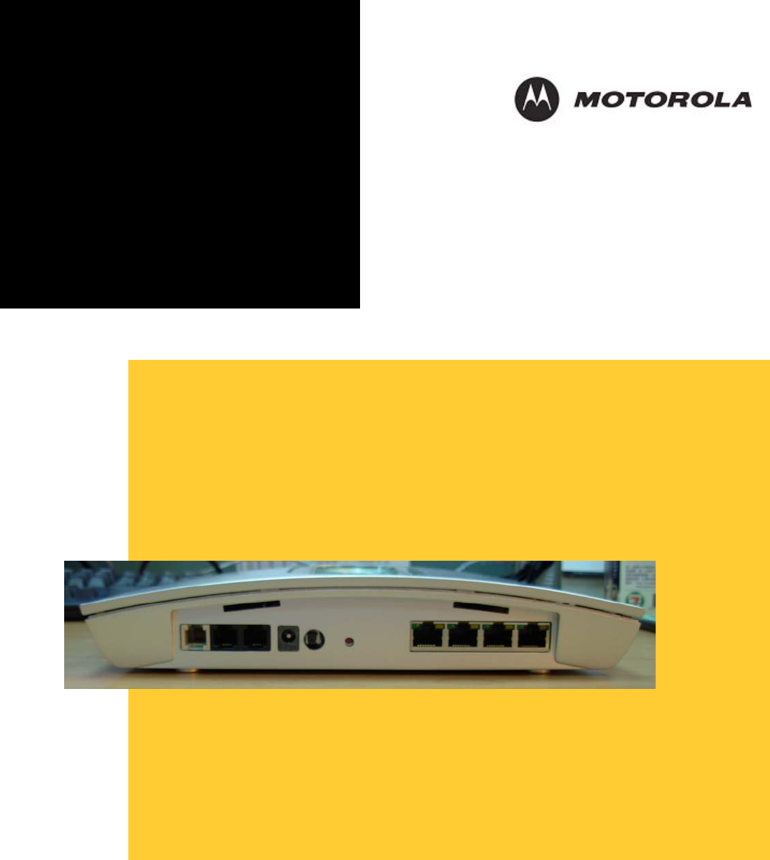
ROUTER PHYSICAL DESCRIPTION..............................................................................11
Back of Router..........................................................................................................11
Top Case of HH1620 ...........................................................................................13
LED Description..................................................................................................13
2. INSTALLATION...............................................................................................14
PHYSICAL INSTALLATION OF THE HH1620...............................................................14
Hardware Setup ...................................................................................................15
Antenna Installation.............................................................................................15
Physical Placement..............................................................................................15
Electrical Connection ................................................................................................16
ESTABLISHING YOUR FIRST CONNECTION TO THE HH1620 ....................................................16
Easy Install Process ..................................................................................................16
Manual Install – Wired Connection ..............................................................................16
Manual Install – Wireless Connection.................................................................17
Configuring Computers to Communicate with the HH1620................................19
Configuring Windows 98SE and ME...................................................................19
Configuring Windows 2000 .................................................................................20
Configuring Windows XP ....................................................................................22
3. CONFIGURATION...........................................................................................24
ACCESSING THE WEB-BASED CONFIGURATION UTILITY ..........................................24
Logging In............................................................................................................24
OVERVIEW OF CONFIGURATION PAGES ....................................................................25
Navigation Between Pages ..................................................................................25
THE DEVICE INFO CATEGORY...................................................................................26
Summary ..............................................................................................................26
WAN.....................................................................................................................26
Statistics – LAN......................................................................................................27
Statistics – WAN...................................................................................................28
Statistics – ATM...................................................................................................28
Statistics – ADSL..................................................................................................29
Statistics – VDSL..................................................................................................29
THE ADVANCED SETUP CATEGORY ..........................................................................30

WAN Setup ...........................................................................................................30
LAN Setup ............................................................................................................31
NAT – Virtual Servers..........................................................................................32
NAT – Port Triggering.........................................................................................32
NAT – DMZ Host .................................................................................................33
Security – IP Filtering – Outgoing ......................................................................34
Security – IP Filtering –Incoming .......................................................................36
Security – Parental Control.................................................................................36
Routing – Default Gateway..................................................................................37
Routing – Static Route .........................................................................................38
Routing – RIP.......................................................................................................39
DNS .......................................................................................................................40
DDNS – Dynamic DNS........................................................................................41
DSL ......................................................................................................................43
Printer Server.......................................................................................................43
Port Mapping.......................................................................................................45
IPSec ....................................................................................................................45
Certificate – Local ...............................................................................................46
Certificate – Trust CA..........................................................................................47
THE WIRELESS CATEGORY .......................................................................................48
Basic.....................................................................................................................48
Security ................................................................................................................49
MAC Filter...........................................................................................................50
Wireless Bridge....................................................................................................51
Quality of Service.................................................................................................52
Station Info...........................................................................................................54
THE VOICE CATEGORY .............................................................................................54
THE DIAGNOSTICS CATEGORY..................................................................................57
THE MANAGEMENT CATEGORY................................................................................58
Settings – Backup.................................................................................................58
SETTINGS – UPDATE .................................................................................................59
SETTINGS – RESTORE DEFAULT................................................................................60
SYSTEM LOG.............................................................................................................61
INTERNET TIME.........................................................................................................61
ACCESS CONTROL – SERVICES .................................................................................62
ACCESS CONTROL – IP ADDRESSES..........................................................................63
ACCESS CONTROL – PASSWORDS .............................................................................63
UPDATE SOFTWARE ..................................................................................................64
SAVE/REBOOT ..........................................................................................................65
4. TROUBLESHOOTING....................................................................................66
APPENDIX. DEVICE SPECIFICATIONS ............................................................72
GLOSSARY................................................................................................................73

Overview
1. Overview
Congratulations on purchasing the Motorola® HH1620 Wireless VoIP Gateway.
The HH1620 includes both an 802.11b/g wireless access point and a 4-port Ethernet router. It
also enables up to two standard analog telephones to use digital telephone services over a
broadband Internet connection. The broadband connection can be any high-speed data
service through either:
A cable modem connected to coaxial cable from a cable television company
A DSL (digital subscriber line) modem connected to telephone wiring from a telephone
company
You can connect up to four computers or other Ethernet devices directly to the HH1620. By
adding hubs or other routers, you can expand your network up to the recommended
maximum of 16 connected devices.
The computers on the HH1620 network must:
Have a 10Base-T or 10/100Base-T Ethernet adapter
Be running Microsoft® Windows®, Macintosh® OS, Linux®, or UNIX®
So it is both wireless and wired, providing the foundation for a truly customized network full of
options.
Using the HH1620, you can share files, pictures, peripherals, printers and more with everyone
else on the network. By connecting a broadband modem (cable, DSL or other), you can also
share a single high speed Internet connection.
The HH1620 offers both the popular 802.11b wireless standard as well as the nearly 5-times-
faster 802.11g standard, providing you the ultimate in flexibility and speed. With Wi-Fi®
Protected Access (WPA™) included, your wireless connections are robust and secure, giving
you the security to communicate without fear that your signal might be compromised.
The HH1620 comes loaded with Performance Enhancement technology that accelerates your
wireless network and your fun. This new technology boosts wireless performance among
compatible Motorola devices up to 35% faster than over standard 802.11g networking.
Upgradeable firmware keeps the router’s control software up-to-date. The HH1620 captures
the latest technology in a package that stays current, protects your home network, and
provides you easy home network management.
HH1620 Wireless VoIP Gateway
User’s Guide 1
Overview
Features
The HH1620 Wireless VoIP Gateway provides:
Up to two lines of robust, full-featured telephone and fax service
Voice-over-data prioritization so you can speak on the phone while using the Internet
with no reduction in voice quality
Full network connectivity in a single unit, eliminating the cost and clutter of stand-alone
routers and hubs
VPN pass-through support for remote access to enterprise applications
Portability to plug into any broadband connection (cable or DSL)
Plug-and-play installation
Compact, low-profile design
Easy Web-based configuration
Support for features such as caller ID, call waiting, three-way calling, and call forwarding
Firewall to help protect your network against external attacks
Connects the laptop wirelessly and allows you to roam unfettered
Supports a multitude of devices that operate with both 802.11g and 802.11b wireless
communication standards
Protects your wireless communications using Wi-Fi Protected Access (WPA), Wi-Fi
Protected Access version 2 (WPA2TM), 802.1X, and Wired Equivalent Privacy (WEP)
security algorithms
Supports peer-to-peer communication using built-in Wireless Distribution System (WDS)
functionality
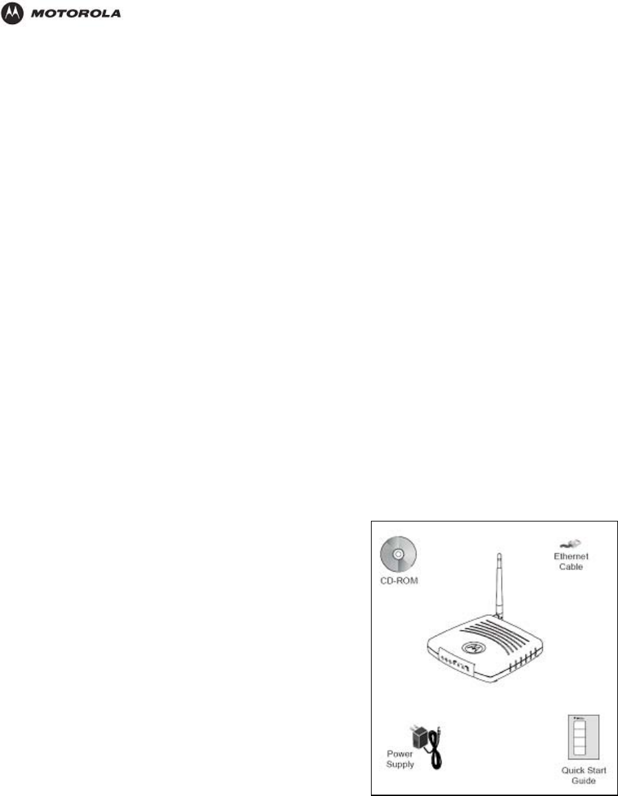
Box Contents
Your box contains the following:
AC Adapter: Connects the HH1620 to an AC electrical
outlet (the plug shown is for the USA; yours may look
different)
Ethernet Cables: Blue cable connects the Internet port
on your HH1620 to your cable or DSL modem Yellow
cable connects an Ethernet port on your HH1620 to a
computer or other network device
Quick Start Guide: Provides instructions to quickly set up
and configure your voice gateway
Telephone Cables: Connect the ADSL port on your
HH1620 to the wall jack. And connect the TEL Port on
your HH1620 to your telephone.
In addition to your HH1620, you also need:
An established DSL or cable Internet connection
One or two touch-tone telephones
One or more computers with these minimum requirements:
Pentium-class processor or faster
16 MB of memory
10 MB of hard disk space available
Windows® 98, Windows 98 SE, Windows Me®, Windows NT®, Windows XP™
A 10/100Base-T category 3 or better straight-through Ethernet cable with RJ-45
terminators for each computer to be wired to the network (the yellow cable provided with
the voice gateway connects one computer)
HH1620 Wireless VoIP Gateway
User’s Guide 2

Overview
If you purchased your HH1620 voice gateway from a retail location, you must first activate
your Xxxxx® Phone Service. You will need to provide the WAN MAC ID on the bottom of the
HH1620.
Precautions
Postpone installation until there is no risk of thunderstorm or lightning activity in the area.
To prevent overheating the HH1620, do not block the ventilation holes on the unit.
Do not open the HH1620.
Caution!
We recommend powering your HH1620 through a surge protector or universal power
supply (UPS).
Gather Information
You may need to obtain the following information about your high-speed Internet connection:
For a DSL connection only, your user name and password
For a cable modem connection using static IP addresses only, your IP address, subnet
mask, default gateway, and DNS server IP address or addresses
If you already have a router, we recommend printing its configuration screens to use for
reference during Basic Configuration.
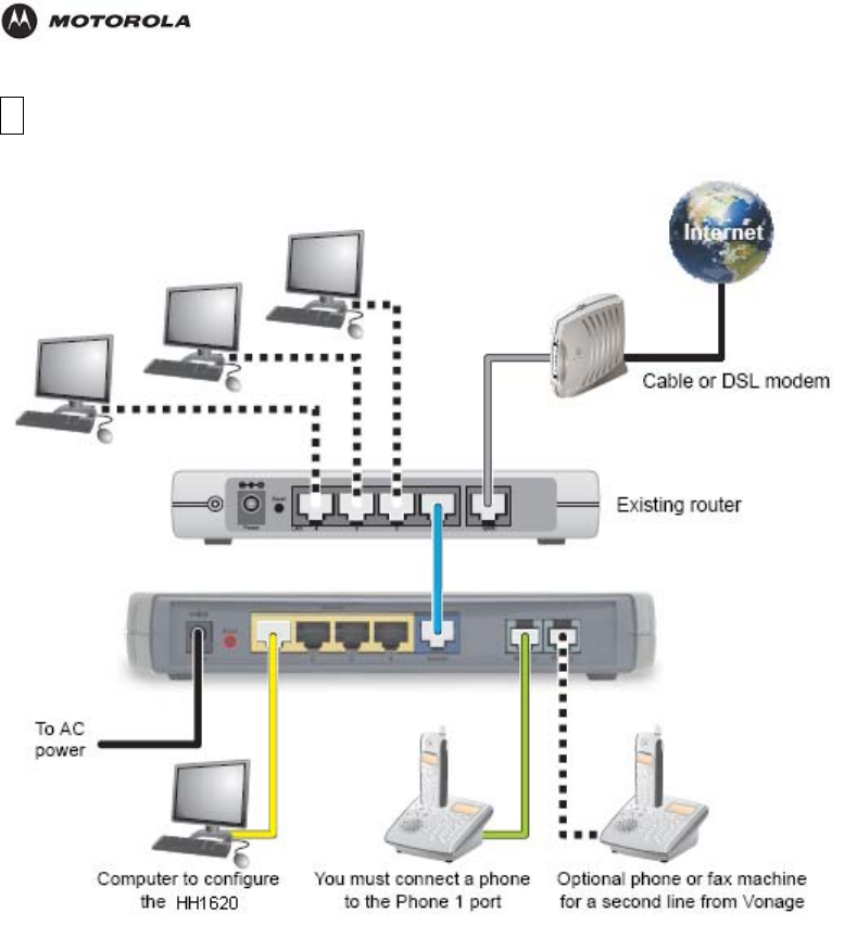
Connect the HH1620
If you already have a router, use instructions A: Installation With an Existing Router.
Note: If you have more than one computer connected to a single Internet connection,
you have a router.
If your cable or DSL modem has a built-in router with multiple computers connected, you
should also use instructions A.
Note: Some cable data and DSL providers supply modems containing a router. If your
modem has multiple Ethernet ports, it probably contains a router. If you are not sure, call
your cable or DSL provider and ask them whether your modem contains a router.
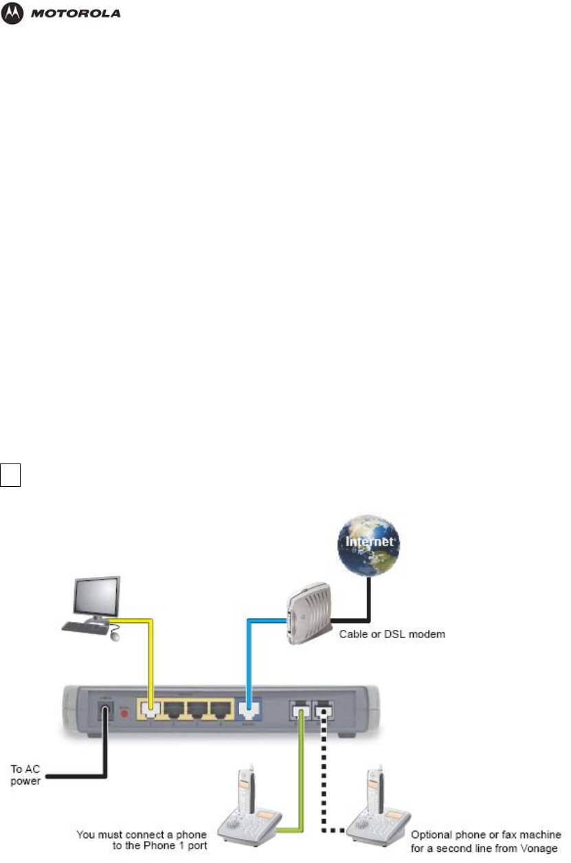
If you have a standard cable or DSL modem with just one computer connected, use
instructions B: Installation With a Standard Modem.
You can place the HH1620 on a flat surface horizontally or vertically. For vertical installation,
insert the voice gateway into the supplied base stand. The voice gateway slides snugly into a
notch in the stand to keep it stable.
HH1620 Wireless VoIP Gateway
User’s Guide 3
Overview
A Installation With an Existing Router
1. Unplug your cable or DSL modem power cord or adapter.
2. Unplug your router power cord or adapter. Please leave your modem and router connected to the
cable or phone line that provides your Internet connection.
3. Disconnect one computer from your router.
4. Connect one end of the blue Ethernet cable to an Ethernet port on your router.
Connect the other end of the blue E
5. thernet cable to the blue Ethernet port labelled Internet on the
. Plug your cable or DSL modem power cord or adapter into an AC power outlet. Refer to the
vided by the modem manufacturer. For example,
startup for a Motorola SURFboard cable modem is complete when its Power, Receive, Send, and
uter to complete its start-up process. Refer to the instructions provided with the router.
r voice gateway to the Power connector on its rear
rear panel of your voice gateway.
6. Connect one end of the yellow Ethernet cable to the Ethernet 1 port on your voice gateway.
7. Connect the other end of the yellow Ethernet cable to the Ethernet port on the computer you
disconnected in step 3.
8instructions provided with the modem.
IMPORTANT: Before you continue, be sure to allow enough time for your modem to complete its
start-up process. Refer to the information pro
Online lights are on and no longer flashing.
9. Plug your router power cord or adapter into an AC power outlet. Be sure to allow enough time for
your ro
10. Connect the power adapter supplied with you
HH1620 Wireless VoIP Gateway
User’s Guide 4
Overview
11.
er
minutes.
We recommend plugging the HH1620 power adapter into an electrical outlet that is grounded and
your computer. The Ethernet 1 light on the HH1620 front panel should light.
t lights are
13. e
Navigator®, or Mozilla Firefox®.
ite.
ubleshooting” on page 66.
If your Internet connection works, go to C “Connecting Your Telephone” on page 12.
panel.
Plug the other end into an AC power outlet.
Th turns on your voice gateway. The HH1620 does not have an On/Off power switch. The Pow
light on the front panel performs a series of blinks as described in “Front Panel” on page 3. You
should not unplug your voice gateway when it is not in use.
is
IMPORTANT: Before you continue, be sure to allow enough time for your voice gateway to
complete its start-up process. HH1620 startup is complete when the Power light on its front panel
lights solid green. This usually takes a few
equipped with a surge protector or UPS.
Turn on
12.
IMPORTANT: Before you continue, be sure the HH1620 Power, Ethernet 1, and Interne
all on.
On your computer, open a Web browser such as Microsoft Internet Explorer, Netscap
14. Check your Internet connection by visiting any webs
If your Internet connection does not work, see “Tro
B Installation With a Standard Modem
. Shut down your computer properly. Follow the instructions provided with the computer.
2.
3. d to the cable or phone line that provides your Internet connection.
1
Unplug your cable or DSL modem power cord or adapter.
Disconnect any cables connecting your computer to the modem. Please leave your
modem connecte
HH1620 Wireless VoIP Gateway
User’s Guide 5

Overview
Hint: Your modem should remain off for about 10 minutes to “clear its memory” so it can
tion
4. ne end of the blue Ethernet cable to the Ethernet port on your modem.
d
the rear panel of your voice gateway.
6.
7.
n
Note: If your high-speed Internet connection was through USB and your computer does
s. You can purchase additional Ethernet
cables from any electronics or computer retailer.
8. efer to
IMPORTANT: Before you continue, be sure to allow enough time for your modem to
d Online lights are on and no longer
9. ts
rear panel.
10.
described in “Front
Panel” on page 3. You should not unplug your voice gateway when it is not in use.
ugh time for your voice gateway
complete its start-up process. HH1620 startup is complete when the Power light on its
s
Power, Ethernet 1, and
, or Mozilla Firefox®.
recognize the HH1620 when you turn it back on. You can continue with the installa
during this time.
Connect o
5. Connect the other end of the blue Ethernet cable to the blue Ethernet port labele
Internet on
Connect one end of the yellow Ethernet cable to the Ethernet 1 port on your voice
gateway.
Connect the other end of the yellow Ethernet cable to the Ethernet port on your
computer.
Hint: Your modem should remain off for about 10 minutes to “clear its memory” so it ca
recognize the HH1620 when you turn it back on. You can continue with the installation
during this time.
not have an Ethernet adapter, see “Troubleshooting” on page 66 for information.
Optionally, you can connect up to three more computers directly to the other HH1620
Ethernet ports (2, 3, or 4) using Ethernet cable
Plug your cable or DSL modem power cord or adapter into an AC power outlet. R
the instructions provided with the modem.
complete its start-up process. Refer to the information provided by the modem
manufacturer. For example, startup for a Motorola SURFboard cable modem is
complete when its Power, Receive, Send, an
flashing.
Connect the power adapter supplied with your voice gateway to the Power port on i
Plug the other end into an AC power outlet.
This turns on your voice gateway. The HH1620 does not have an On/Off power switch.
The Power light on the front panel performs a series of blinks as
IMPORTANT: Before you continue, be sure to allow eno
to
front panel lights solid green. This usually takes a few minutes.
We recommend plugging the HH1620 power adapter into an electrical outlet that i
grounded and equipped with a surge protector or UPS.
11. Turn on your computer. The Ethernet 1 light on the HH1620 front panel should light.
IMPORTANT: Before you continue, be sure the HH1620
Internet lights are all on.
12. On your computer, open a Web browser such as Microsoft Internet Explorer, Netscape
Navigator®
HH1620 Wireless VoIP Gateway
User’s Guide 6

Overview
3. Check your Internet connection by visiting any website.
nection does not work, continue with step 14.
users:
es
efore you turned it back on.
dem unplugged for at least 10 minutes does not correct your problem,
. Please contact them to
N MAC ID on the bottom of
n” on page 12.
DSL modem users:
ME page
rop-down list, choose
ally use to log in to your DSL service.
Click Connect to start your Internet connection.
st your Internet connection.
Whe 2.
C C
1
If your Internet con
If your Internet connection works, go to C “Connecting Your Telephone” on page 12.
14. Depending on whether your high-speed Internet service is cable or DSL, do one of the
following:
Cable modem
First, as mentioned in step 3, be sure your cable modem remained off for at least 10 minut
b
If leaving the cable mo
you may need to register your HH1620 with your cable provider
update your information. You need to provide them with the WA
the HH1620.
Whe your Internet connection works, go to C “Connecting Your Telephone
You may need to configure PPPoE to work with your HH1620:
On a com
puter connected to one of the HH1620 Ethernet ports, open a Web browser.
In the Address field, type http://192.168.15.1 and press ENTER.
In the Username and Password fields, type router and click Log In. The HO
is displayed.
Click SETUP followed by WAN Configuration. From the Type d
PPPoE:
Type the Username and Password you norm
In the Keep Alive field, type 0 to ensure that your DSL link is always active.
Click Save. Go back to step 13 to te
For details and more screen shots, see “Logging In to the HH1620” on page 14 and
“WAN Setup for PPPoE (DSL)” on page 18.
n your Internet connection works, go to C “Connecting Your Telephone” on page 1
onnecting Your Telephone
1. In the United Kingdom, connect your BT telephone cord to the Telephone Jack Adapter.
Connect the adapter to the green Phone 1 port on the HH1620.
one line from Xxxxx, you must connect your phone to
2. om Xxxxx, connect a telephone or fax
. Check for a dial tone. If you hear a recording instructing you to connect your phone to
the Phone 1 port, please do so. If you hear neither this message nor a dial tone, refer to
your installation:
d States, call 1-800-342-1791.
In the United States, connect a telephone cord to the green Phone 1 port on the
HH1620.
If you only subscribed to one ph
the Phone 1 port.
If you subscribed to a second phone or fax line fr
machine to the Phone 2 port.
3
“Troubleshooting” on page 66.
4. If you hear a dial tone, to complete
In the United Kindom, call 0207 993 8973.
In the Unite
HH1620 Wireless VoIP Gateway
User’s Guide 7
Overview
,
work (LAN) using a HH1620 than with
sic operation, most default settings require no
less you have sufficient networking knowledge, we
, see “Advanced Configuration” on page 23.
Basic Configuration
The HH1620 provides a graphical user interface (GUI) to configure Ethernet, router, DHCP
nd security settings.
a
It is much easier to configure your local area net
traditional networking equipment. For ba
modification.
If DHCP is enabled on all of the computers on your home network (LAN), you do not need to
change any of the default LAN settings. Un
recommend not changing any LAN settings.
tion
For information about advanced configura
Logging In to the HH1620
1. On a computer connected to the HH1620, open a Web browser.
2. In the Address or Location field, type http://192.168.1.1 and press ENTER to display:
3. In the Username field, type admin.
4. In the Password field, type the admin.
5. Click OK to log in to the main page:
WA
1.
2. ic
3.
. From the Type drop-down list, choose one of:
l DSL modems See “WAN Setup for PPPoE (DSL)” on
N Configuration
Log in to the HH1620 (see “Logging In to the HH1620” on page 14).
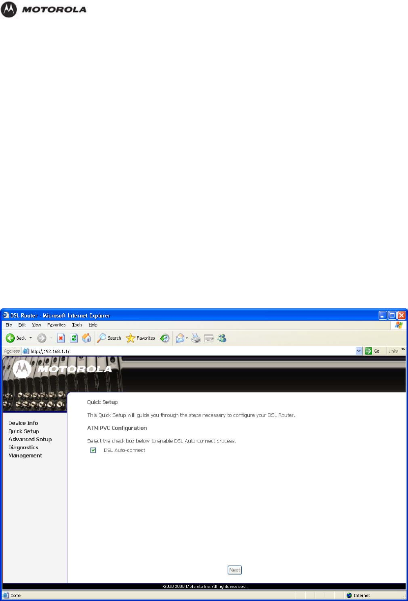
Click Qu k Setup.
Click WAN Configuration.
4PPPoE PPPoE is used with al
page 18
HH1620 Wireless VoIP Gateway
User’s Guide 8

Overview
Static For some cable modems, the cable company assigns the cable modem a
ress, subnet mask, default
sses.
See “WAN Setup for a Static IP Address (Cable Modem)” on page 19.
DHCP Most cable modems have a dynamic IP address assigned by the cable
nal configuration is needed for the HH1620.
” on page 20.
(DSL)
AN Setup for DHCP (Cable Modem)
t need
ny of t
g TCP/
ave s
settings.
Field or Button D
Subnet IP bnetwork IP address in dotted-decimal format. We
static (unchanging) IP address. You must provide the IP add
gateway, and one to three domain name server (DNS) addre
company DHCP server. Typically no additio
See “WAN Setup for DHCP (Cable Modem)
WAN Setup for PPPoE
WAN Setup for a Static IP Address (Cable Modem)
W
LAN Configuration
nableIf DHCP is e
to change a
“Configurin
d on all of the computers on your home network (LAN), you should no
he default LAN settings. For information about enabling DHCP, see
IP” on page 54.
Unless you h ufficient networking knowledge, we recommend not changing any LAN
Figure
escription
Sets your LAN su
Address recommend not changing the default 192.168.1.1.
Netmask sk, in dotted-decimal format. The default is
ers
Sets the HH1620 subnet ma
255.255.255.0, which enables the HH1620 router to support up 253 us
connected through multiple hubs, switches, routers, or wireless access
points.
Default Gateway
Sets the default gateway IP address for your network, in dotted-decimal
format. It must be in the range for the subnet specified by Subnet IP
Address and Netmask. We recommend not changing the default
192.168.1.1.
Host Name Sets the voice gateway host name. It can contain any alphanumeric
characters, except spaces.
Domain Sets the domain name. It is used in conjunction with the host name to
uniquely identify the voice gateway. To access the web pages of the voice
gateway you can type 192.168.15.1 (the IP address) or mygateway1.rgw
(hostmame.domain).
Advanced Setup
This section describes the Advanced Setup menus.
The ADVANCED menu provides the following links:
HH1620 Wireless VoIP Gateway
User’s Guide 9

Overview
Understanding Functions
Before installing your wireless router, please take a few minutes to review the wireless
networking functions described in this section.
Router
Generally, routers connect two networks together. The HH1620 connects your home network
with the Internet, which can be thought of as a very large network.
The router’s firewall inspects each packet of data as it flows in from the Internet before
delivering it to the appropriate PC. Network Address Translation (NAT) protects the privacy of
the IP addresses of devices on your home network, by translating them into a single address
when visible to the public Internet. This is how your network remains protected and private on
the Internet.
LAN (Local Area Network)
A local area network provides a full-time, high-bandwidth connection over a limited area such
as a home, building, or campus. Ethernet is the most widely used LAN standard.
TCP/IP
Transmission Control Protocol/Internet Protocol (TCP/IP) comprises the backbone of the
Internet. IP moves packets of data between nodes while TCP verifies delivery from client to
server. Every device you hook up to your wireless router identifies itself with an IP address.
You are able to assign devices on your network with either a static or dynamically assigned IP
address.
Static IP Address
A static IP address is a fixed address that is assigned manually to a device on the network.
Static IP addresses must be unique and cannot be shared, therefore they are used in
situations where the address should never change, like print servers or PC servers.
If you are using your wireless router to share an Internet connection, your Internet Service
Provider (ISP) might have assigned you a static IP address, which you will use when
configuring your router. See Section 3: Configuration.
Dynamic IP Address
A dynamic IP address is a temporary IP number, dynamically or randomly generated by a
DHCP server. The address lasts only as long as the server allots, usually in the space of a
day or two. When the IP address expires, the client is automatically reassigned a new IP
address, ensuring smooth communication.
If you are using your wireless router to share an Internet connection, your ISP might have
assigned you a dynamic IP address, which you use when configuring your router. See
Section 3: Configuration.
DHCP Server
A Dynamic Host Configuration Protocol (DHCP) Server assigns IP addresses to clients
connected to the router. A client is any device that can connect with your router. The client
(PC, gaming device, etc.) is automatically assigned an IP address every time a device is
added to your network, which frees you from manually assigning IP addresses.
HH1620 Wireless VoIP Gateway
User’s Guide 10
Overview
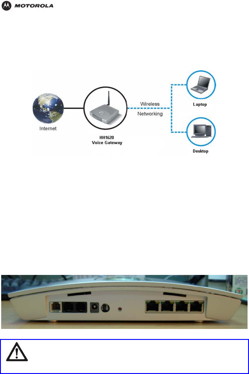
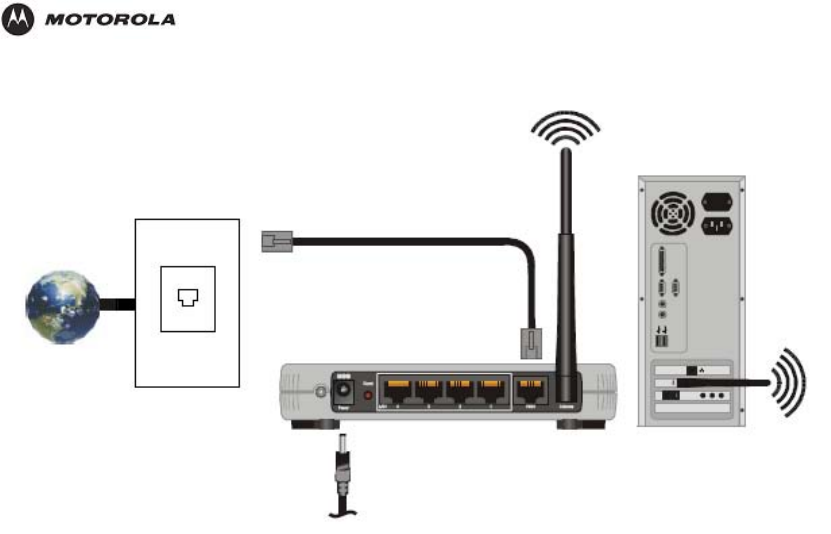
Sample Home Network Diagram
Your wireless router serves as the centerpiece of your network, allowing you to share files,
printers, and the Internet connection. A sample home network is shown below:
The Internet communicates with the modem, which in turn communicates with the router.
The router acts as the gateway to your network; it sends devices information such as
requests for Internet access, file sharing, or multiplayer games. The router controls the
information for your network, intelligently routing the information to its required destination
while at the same time protecting your network from the public domain.
Router Physical Description
The following sections describe the physical characteristics of your router.
For instructions on installing your router, see Section 2: Installation.
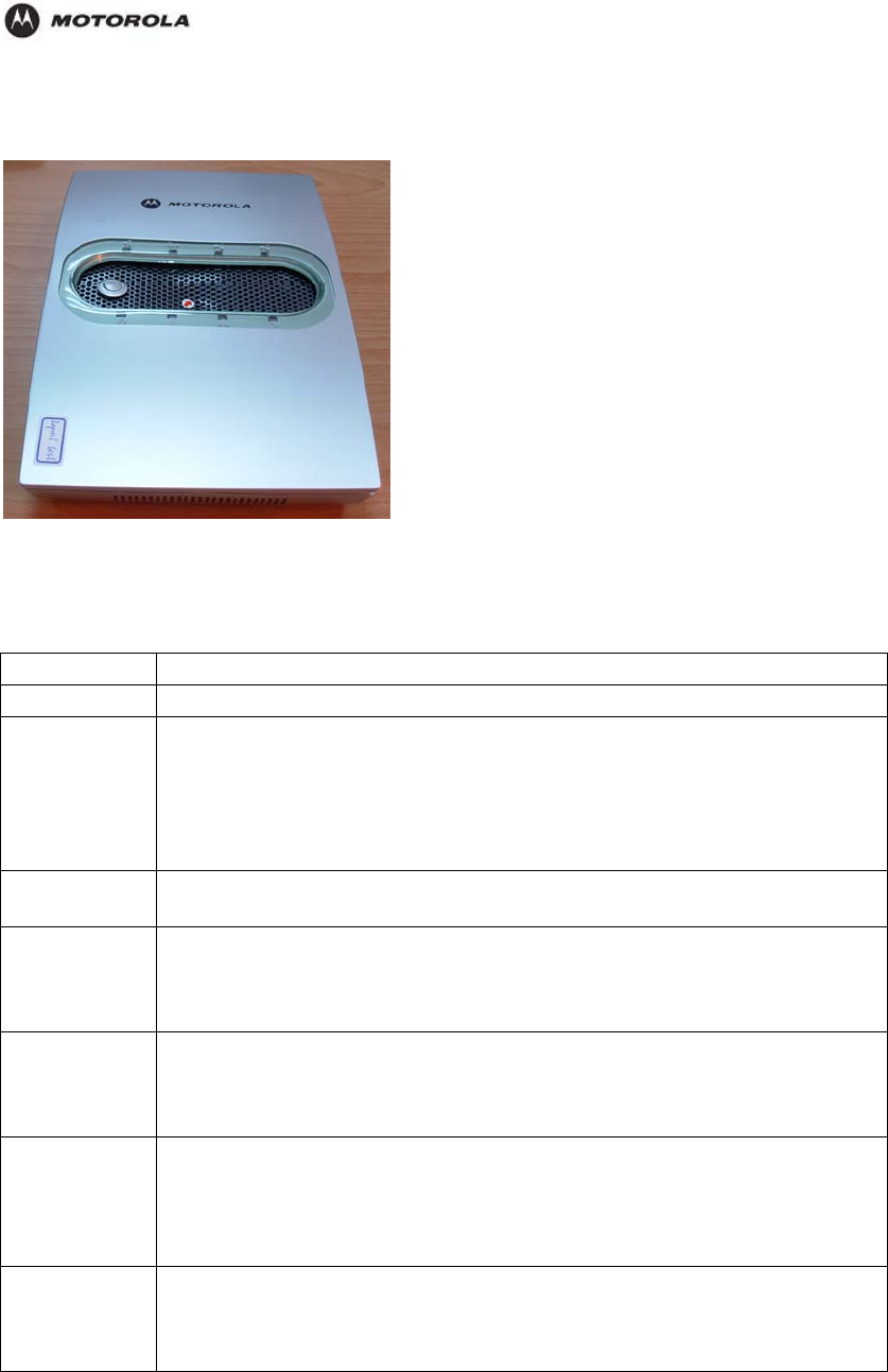
Back of Router
The following illustration shows the HH1620 back panel:
WARNING!
Using a power supply with a different voltage rating than the one included with
the HH1620 will cause damage and void the warranty for this product.
HH1620 Wireless VoIP Gateway
User’s Guide 11

Overview
Feature Description
Power Connector for a 12 V adapter that you plug into an AC power outlet
Reset
Button Resets your router or resets the router to the default login settings.
If the router experiences trouble connecting to the Internet, briefly press and
release the Reset button to reset the router. This retains the router’s
configuration information.
To reset the router to the factory defaults, press and hold the Reset button for
more than five seconds. This clears the HH1620’s Username, Password, IP
Address, Subnet Mask and Operation Mode.
LAN 1,2,3 These three ports connect the router to your LAN or home network using
Ethernet cables. This enables communication among clients, such as PCs or
print servers, on the network. The LAN ports support either 10-BASE-T or 100-
BASE-T transmission speeds as well as straight-through and crossover
Ethernet cables.
Any of these three ports can also serve as an uplink port to other network
devices, such as another router or switch, which allows you to extend your
network.
WAN This port serves as an uplink port to other network devices, such as router or
switch, which allows you to extend your network.
TEL1, 2 Connect your HH1620 to the standard analog telephone(s) using this port with
your supplied RJ-11 cables.
This enables your HH1620 to make calls via the Internet.
ADSL Connect your HH1620 to the ADSL wall outlet using this port with your supplied
RJ-11 cable.
This enables your HH1620 to access the Internet.
USB This port connects the router to your computer using USB cables.
Printer Port This port connects the router to printer using a USB cable. This feature is used
to share the printer on the network.
Antenna The antenna is used for wireless connections. You are able to rotate the
antenna to gain the best signal reception.
HH1620 Wireless VoIP Gateway
User’s Guide 12
Overview
Top Case of HH1620
The following illustration shows the HH1620 front panel:
The LEDs of the router indicate its operational status.
LED Description
LED Description
Power Indicates the unit is powered on.
Status/Alarm The Status LED will flash when performing a self-test/booting up or is
registering with the service provider. The Status LED will flash green slowly
when the system is connected with the service. The
A
larm LED will light solid
red if the self-test or boot up fails. The Alarm LED will flash red slowly when
the system is ready but cannot receive an acknowledgement from the
service.
Prov This LED flashes when the device has established a connection and
received authorization from your service provider.
WAN When a connection is established the 10 or 100 LED will light up solid. The
LED will blink to indicate activity. If the 10 or 100 LED does not light up when
a cable is connected, verify the cable connection and make sure your device
is powered on.
LAN1-3 When a connection is established the 10 or 100 LED will light up solid on the
appropriate port. The LEDs will blink to indicate activity. If the 10 or 100 LED
does not light up when a cable is connected, verify the cable connections
and make sure your devices are powered on.
Phone1-2 This LED displays the VoIP status and Hook/Ringing activity on the phone
port that is used to connect to your normal telephone(s)/fax machine and
regular telephone line. If a phone connected to a phone port is off the hook
or in use, this LED will light solid. When a phone is ringing, the indicator will
blink.
ADSL When a DSL connection is established, this LED will light up solid. The LED
will blink to indicate activity. If it does not light up when a DSL cable (RJ-11
line) is connected, verify the cable connection and make sure your device is
powered on.
HH1620 Wireless VoIP Gateway
User’s Guide 13

Troubleshooting
2. Installation
This section will help you:
physically install your HH1620, and
establish a first connection between a PC and the HH1620.
Once this first connection is made, you can configure the HH1620 to support all of the other
wired and/or wireless connections you need.
Physical Installation of the HH1620
Positioning Your HH1620 for Optimal Wireless Performance
The HH1620 uses a radio transmission technology defined by the Institute of Electrical and
Electronics Engineers (IEEE) called 802.11 Wireless Fidelity (Wi-Fi). This standard is
subdivided into distinct categories of speed and the frequency spectrum used, designated by
the lower case letter after the standard.
For example, your router supports both the ‘b’ and ‘g’ specifications. The 802.11b
specification transmits data rates up to 11 Mbps while the 802.11g specification transmits
data rates up to 54 Mbps. These are theoretical standards so your performance may vary.
The radio waves radiate out in a donut-shaped pattern. The waves travel through walls and
floors, but transmission power and distance are affected. The theoretical distance limit is
1,000 feet (305 meters), but actual throughput and distance varies.
Both standards operate in the 2.4 GHz range, meaning other electrical appliances also might
interfere with the router – televisions, radios, microwave ovens, or 2.4 GHz cordless
telephones. Therefore, positioning your router where it encounters the least interference helps
maintain a better connection.
The following lists the expected wireless range of the router. This table is only a guide and
coverage varies due to local conditions.
Data Rate Open Area Closed Area
54 Mbps Up to 100 ft (30m) Up to 60 ft (18m)
11 Mbps Up to 900 feet (275 m) Up to 160 feet (49 m)
5.5 Mbps Up to 1300 feet (396 m) Up to 200 feet (61 m)
2 or 1 Mbps Up to 1500 feet (457 m) Up to 300 feet (91 m)
To achieve the best wireless performance, review these guidelines before deciding where to
place your router:
Placing your base station in the physical center of your network is the best location
because the antenna sends out the signal in all directions.
Placing the router in a higher location, such as on top of a cabinet, helps disperse the
signal cleanly, especially to receiving locations on upper stories.
If possible, position your router so there is direct line of sight between the router and
your other home network devices.
Avoid placing the router next to large solid objects like computer cases, monitors, walls,
fireplaces, etc. This helps the signal penetrate more cleanly.
Other wireless devices like televisions, radios, microwaves, and 2.4 GHz cordless
telephones can interfere with the signal. Keep these devices away from the router.
Mirrors, especially silver-coated, can reduce transmission performance.
HH1620 Wireless VoIP Gateway
User’s Guide 14
Troubleshooting
Hardware Setup
Hardware setup includes:
Antenna Installation: connecting the antenna to the router
Physical Placement: how and where you physically place your router
Electrical Connection: how to connect the power cord
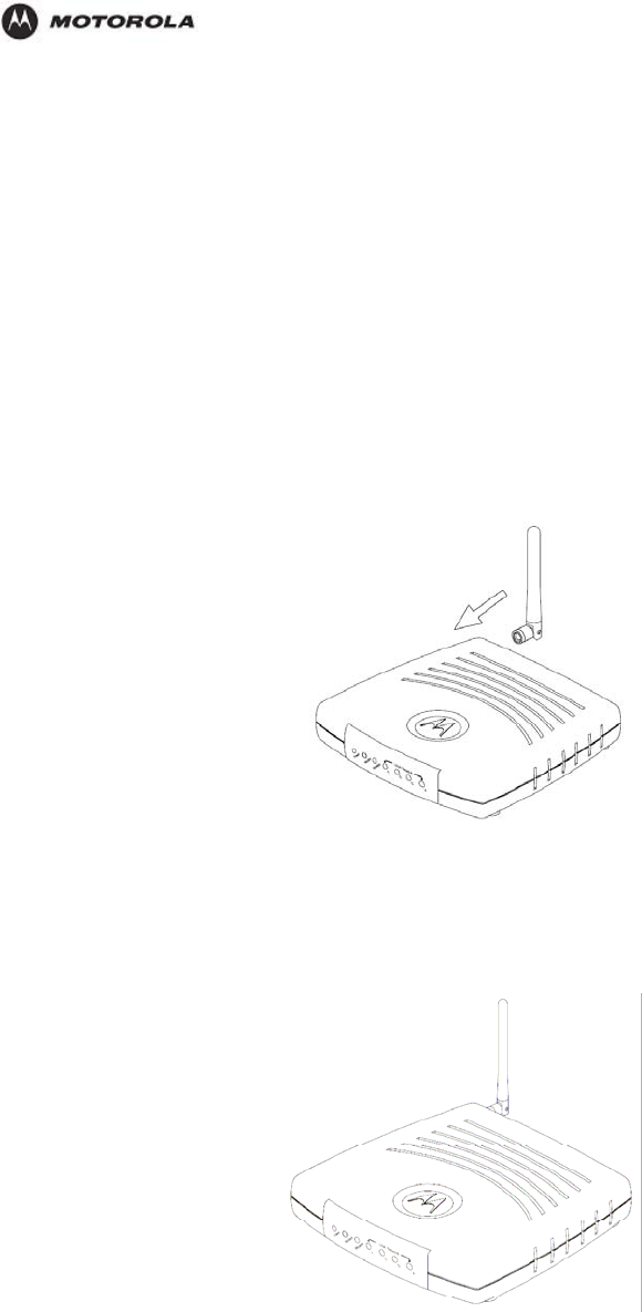
Antenna Installation
When shipped, the antenna for the HH1620 is not connected to the router. To attach the
antenna to the router:
1. Locate the antenna port on the back of the router (the threaded knob).
2. Screw the antenna connector clockwise on to the threaded knob until firmly seated. Do
not over-tighten.
Physical Placement
1. Place the router in the desired location and follow the procedures below for connecting
and configuring the router.
2
. Follow the installation procedures for connecting and configuring the router.
HH1620 Wireless VoIP Gateway
User’s Guide 15
Troubleshooting
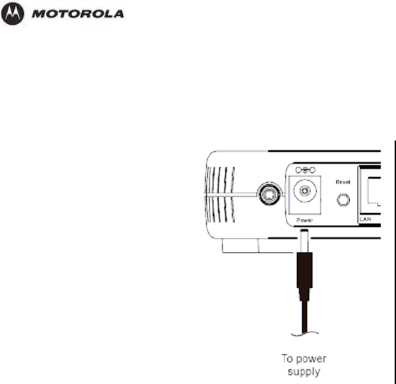
Electrical Connection
Your router does not have an On/Off power switch and therefore will only be powered on by
plugging in the power adapter.
1. Connect the power adapter to the router’s Power port, found on the back of the router.
2. Plug the power adapter into a grounded and surge-protected power outlet. The Power
LED on the front panel lights green when connected properly.
Establishing Your First Connection to the HH1620
Once the HH1620 is placed, you can now establish your first PC connection to the HH1620.
There are three ways to choose from to accomplish this:
If your first connection will be a wired connection (i.e., an Ethernet cable will connect the
PC and the HH1620), you can follow the step-by-step easy install process with the
included HH1620 Installation Wizard CD-ROM. (recommended)
If your first connection will be a wired connection, but you do not wish to use the
HH1620 Installation Wizard CD-ROM, you can manually install this first wired
connection.
If your first connection will be a wireless connection, you can manually install this first
wireless connection.
Easy Install Process
Run the Installation Wizard program from the supplied CD-ROM to quickly set up your
network. Once your network is up and running, for advanced configuration, see Section 3:
Configuration.
The Installation Wizard will automatically run once you place the CD-ROM in your PC’s CD-
ROM drive. It will confirm that the antenna and electrical connections have been made, and
then lead you step-by-step through setting up your HH1620 in a typical configuration as a
wired/wireless router.
Manual Install – Wired Connection
If you are manually connecting your PC with an Ethernet cable to the router, your PC must be
installed first with an Ethernet adapter. You need two Ethernet cables for this procedure, one
to connect the router to the modem and one to connect a PC to the router.
Figure
1. If you are currently running broadband to a single computer: Unplug the Ethernet cable
that runs between your modem and PC from the back of your PC and plug it into the
HH1620 Wireless VoIP Gateway
User’s Guide 16

Troubleshooting
ion to access the built-in Web-based Configuration Utility and configure the
t as
are labeled with black letters.
port labeled WAN on the back of your router.
If you are not running broadband to a single computer: Connect an Ethernet cable to the
WAN port on your router.
2. Connect the other end of the same cable to your cable or DSL modem. You have now
connected the router to the modem. It will be necessary to restart your cable or DSL
modem after making this connection.
3. To connect the PC to the router, use a second Ethernet cable and connect it to the
Ethernet port on your PC.
4. Connect the other end of the same cable into one of the LAN ports on your router. You
have now connected your PC to the router.
5. Your PC’s Ethernet adapter may need to be configured to work with the HH1620.
By default, the HH1620 has a LAN IP Address of 192.168.1.1, and dynamically assigns
an IP Address to connected devices. The PC will not communicate properly with the
HH1620 if the Ethernet adapter is not configured either:
(a) to accept a dynamic IP Address, or
(b) with a compatible static IP Address (i.e., 192.168.10.x, where x is a number between
2 and 254).
To make any necessary adjustments to your PC’s Ethernet Adapter, you can follow the
instructions in this section under Configuring Computers to Communicate with the
HH1620.
NOTE: You can make wired connections between the HH1620 and other devices by
repeating Steps 3, 4, and 5 with each of those devices.
6. Once the PC is communicating with the HH1620, you can proceed to Section 3:
Configurat
HH1620:
For a typical HH1620 configuration as a wired/wireless router, review and adjus
necessary only those configuration options designated as “commonly used” or
“recommended”. These fields are labeled with white letters.
For advanced HH1620 configuration, review and adjust any and all configuration
options as desired. Field codes requiring more advanced knowledge to configure
Manual Install – Wireless Connection
ARNING!
When first configuring your router, it is recommended that you have an Ethernet
cable connected to the router. Performing the INITIAL configuration using a
wireless connection is not secure and is not recommended. After you have
finished the initial configuration of the router, your connect
you can safely use either a wired or wireless connection. ion will be secure and
W
If you are connecting your client wirelessly to the router, you can use the Motorola WPC
or WPCI810GP, a wireless PCI adapter for your desktop PC. If you have a laptop, the
Motorola WN825G or WN825GP wireless PC card adapter provides access. A Mo
I810G
torola
U830G wireless USB adapter can also provide access for desktops or laptops.
W
HH1620 Wireless VoIP Gateway
User’s Guide 17
Troubleshooting
1. If you are currently running broadband to a single computer, unplug the Ethernet cable
that runs between your modem and PC from the back of your PC and plug it into the
port labeled WAN on the back of your router.
If you are not running broadband to a single computer, connect an Ethernet cable to the
WAN port on your router.
2. Connect the other end of the same cable to your cable or DSL modem. You have now
connected the router to the modem. It will be necessary to restart your cable or DSL
modem after making this connection.
3. Your PC’s wireless adapter may need to be configured to work with the HH1620.
By default, the HH1620 has a LAN IP Address of 192.168.1.1, and dynamically assigns
an IP Address to connected devices. The PC will not communicate properly with the
HH1620 if the wireless adapter is not configured either:
(a) to accept a dynamic IP Address, or
(b) with a compatible static IP Address (i.e., 192.168.10.x, where x is a number between
2 and 254).
To make any necessary adjustments to your PC’s wireless adapter, you can follow the
instructions in this section under Configuring Computers to Communicate with the
HH1620.
4. To connect the PC to the HH1620 through a wireless connection, use your PC’s
wireless adapter utility to verify:
(a) the selection of the SSID (Service Set Identifier) of the HH1620, which by default is
set to motorolaABCDEF012345, where the final 12 characters represent the HH1620’s
Wireless MAC address (see the image below to identify the HH1620’s Wireless MAC
address from the product label),
fig
(b) that authentication is set to Open, since the HH1620 by default has no wireless
authentication enabled, and
(c) that no encryption is enabled, since the HH1620 by default has no wireless
encryption enabled.
Refer to your wireless adapter’s documentation for instructions on how to review and
adjust these settings.
NOTE: You can make wireless connections between the HH1620 and other devices by
repeating Steps 3 and 4 with each of those devices, but it is recommended to wait until
after securing your wireless network to do so.
HH1620 Wireless VoIP Gateway
User’s Guide 18
Troubleshooting
5. Once the PC is communicating with the HH1620, you can proceed to Section 3:
Configuration to access the built-in Web-based Configuration Utility and configure the
HH1620:
For a typical HH1620 configuration as a wired/wireless router, review and adjust as
necessary only those configuration options designated as “commonly used” or
“recommended”. These fields are labeled with white letters.
For advanced HH1620 configuration, review and adjust any and all configuration
options as desired. Field codes requiring more advanced knowledge to configure
are labeled with black letters.
In either case, it is recommended that you first use the Web-based Configuration Utility
to establish security measures on your wireless network, and re-connect securely to the
HH1620, prior to making any other changes to the HH1620.
Configuring Computers to Communicate with the HH1620
Each computer that will be part of your network needs to communicate with the router. To do
this, you may need to configure each PC’s network settings to automatically obtain an IP
address.
This section includes information on configuring computers with the following operating
systems:
Windows® 98SE
Windows Me®
Windows® 2000
Windows XP™
Determine the operating system for each computer you will include in your wireless network
and follow the steps to configure the network settings for that PC.
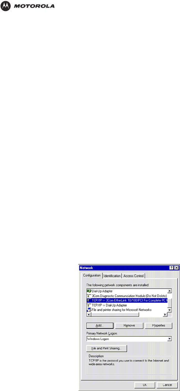
Configuring Windows 98SE and ME
1. Select Start > Settings > Control Panel.
2. Double-click Network. The Network window is displayed.
3. On the Configuration tab, select the TCP/IP line the for the appropriate wired or
wireless Ethernet adapter on your PC. There may be multiple adapters installed –
choose only the one that is configured for your adapter. In the example above, a 3Com
Ethernet adapter card is installed and is the appropriate choice.
4
. PropertiesClick . The TCP/IP Properties window is displayed.
HH1620 Wireless VoIP Gateway
User’s Guide 19
Troubleshooting
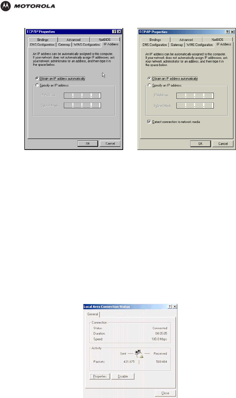
Windows 98SE Windows ME
5. Click the IP Address tab.
6. Select Obtain an IP address automatically.
7. Click OK.
8. Click the Gateway tab and confirm that the Installed Gateway field is blank.
Click OK twice. Windows may ask for the Windows Installation disk. First check to
the installation files are installed at c:\windows\options\cabs. Otherwise, load your
9. see if
0. Restart your computer to save your settings.
3. ick the Local Are red or wireless Ethernet
adapter.
Windows CD and follow the prompts.
1
Configuring Windows 2000
1. Select Start > Settings > Control Panel.
2. Double-click Network and Dial-Up Connections.
Double-cl a Connection appropriate for your wi
4. The Local Area Properties window is displayed.
Click Properties.
HH1620 Wireless VoIP Gateway
User’s Guide 20
Troubleshooting
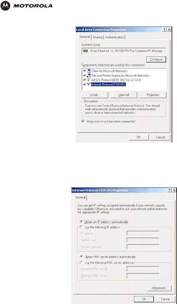
5. Ensure the box next to Internet Protocol (TCP/IP) is selected.
6. Click to highlight Internet Protocol (TCP/IP) and click Properties.
The Internet Protocol (TCP/IP) Properties window is displayed.
7. Select Obtain an IP address automatically. Click OK twice to exit and save your
settings.
8. Restart your computer to save your settings.
HH1620 Wireless VoIP Gateway
User’s Guide 21
Troubleshooting
Configuring Windows XP
This configuration assumes you have retained the default interface for Windows XP. If you
are running the ‘Classic’ interface, please follow the instructions for Windows 2000.
1. Select Start > Settings > Control Panel.
2. Double-click Network and Dial-Up Connections.
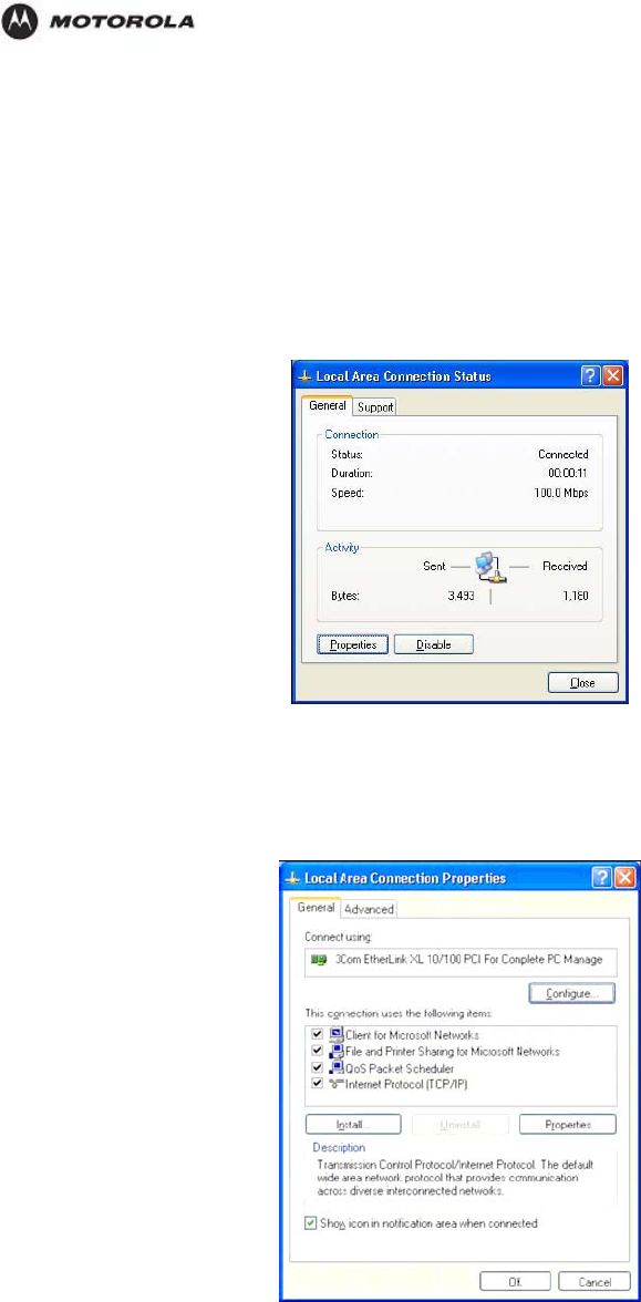
3. Double-click the Local Area Connection appropriate for your wired or wireless Ethernet
adapter.
4. Click Properties.
The Local Area Properties window is displayed.
5. Ensure the box next to Internet Protocol (TCP/IP) is selected.
HH1620 Wireless VoIP Gateway
User’s Guide 22
Troubleshooting
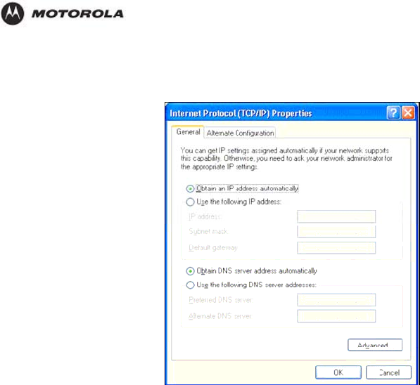
6. Click to highlight Internet Protocol (TCP/IP) and click Properties.
The Internet Protocol (TCP/IP) Properties window is displayed.
7. Click Obtain an IP address automatically. Click OK twice to exit and save your
settings.
HH1620 Wireless VoIP Gateway
User’s Guide 23
Configuration
3. Configuration
This section describes how to use the Web-based Configuration Utility built into your HH1620
Wireless Broadband Router. This utility allows you to customize the HH1620 to meet your
specific needs.
The Web-based Configuration Utility provides several pages of configuration options.
These configuration options are factory set to default values, based on the typical use of the
HH1620 as a wired/wireless router. When you login to the utility for the first time, you will find
all options set to these factory defaults, unless you have already made changes by running
the HH1620 Installation Wizard CD-ROM.
In fact, if you have already used the HH1620 Installation Wizard CD-ROM to initially set up
your router, in many cases you will not need to adjust any other configuration options.
Where adjustments of configuration options are required, additional online help is provided
through “rollover” descriptions. While using the Web-based Configuration Utility, as you roll
your mouse cursor over the name of any configuration option, a brief description of that option
will be displayed.
Note
The screenshots shown are intended for reference only; your version of firmware
may differ slightly.
Accessing the Web-Based Configuration Utility
Logging In
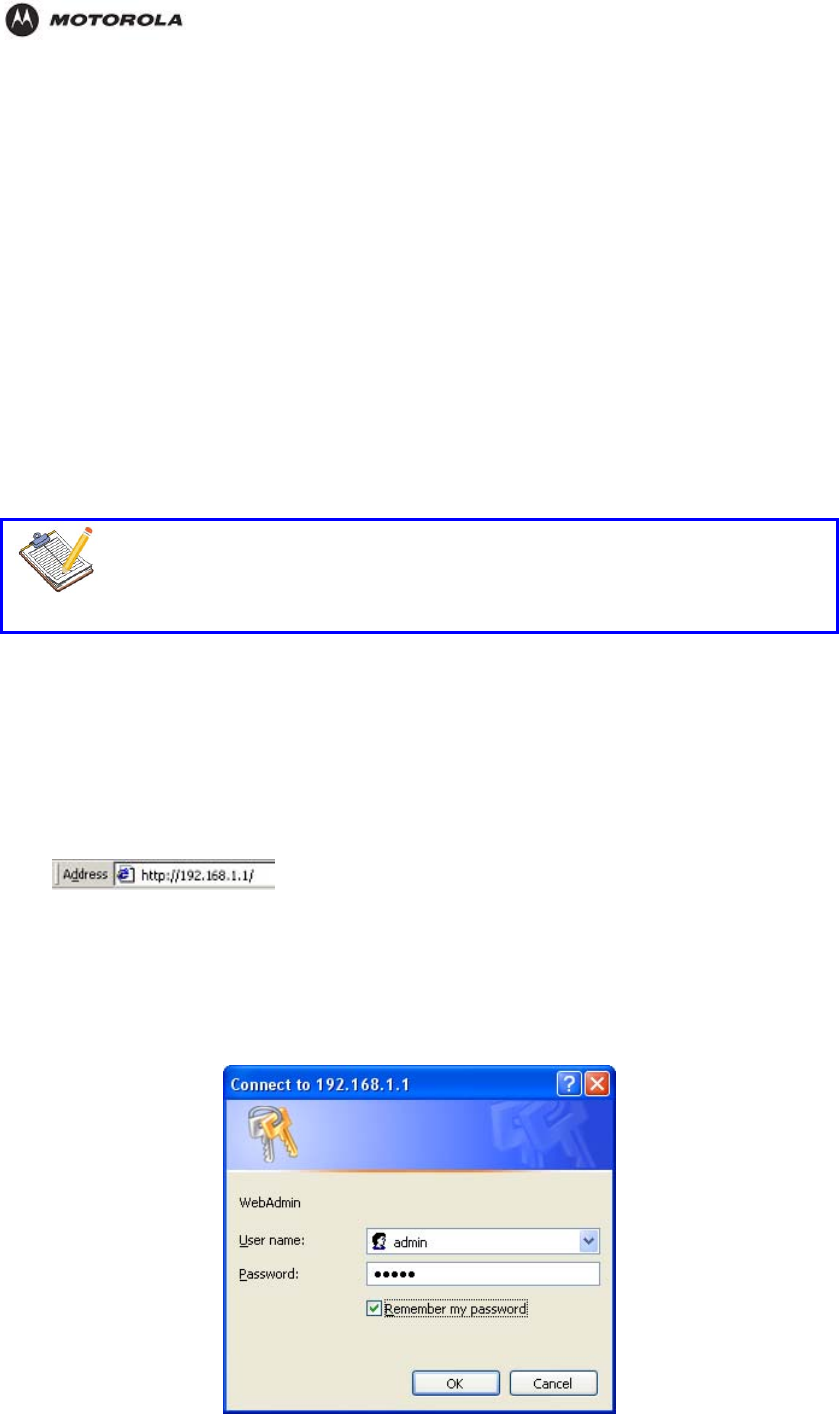
1. Once the router is connected, open your web browser. In the URL field enter
http://192.168.1.1 (the router’s default IP address). Press the Enter key.
The login window will appear (the HH1620 login window is shown in the example below):
2. Enter the User Name. The default factory setting is admin.
3. Enter the Password. The default factory setting is admin.
Once you have logged in, for security reasons you should change the User ID and
Password. See below.
HH1620 Wireless VoIP Gateway
User’s Guide 24
Configuration
4. Click OK to enter the Web-based Configuration Utility.
The Main page will appear when entering the Web-based Configuration Utility.
Overview of Configuration Pages
Navigation Between Pages
The Web-based Configuration Utility is made up of nine configuration pages, each with
configuration options tied to different functions of the HH1620. A “selection bar,” listing all of
these configuration pages, appears at the top of each configuration page.
Figure 3-2 Configuration Page Selection Bar
You can access any page by moving the cursor over a specific configuration page title in the
selection bar, and clicking on the page title.
These configuration categories are as follows:
Device Info:
Advanced Setup:
Wireless:
Voice:
Diagnostics:
Management:
What follows are page-by-page descriptions of the configuration options available.
HH1620 Wireless VoIP Gateway
User’s Guide 25
Configuration
The Device Info Category
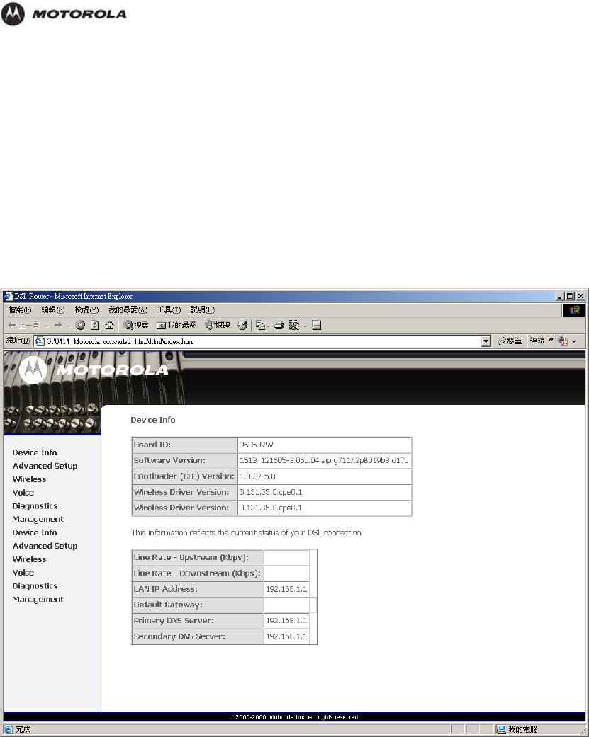
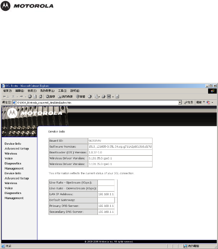
It is the first page you see when entering the Web-based Configuration Utility.
Summary
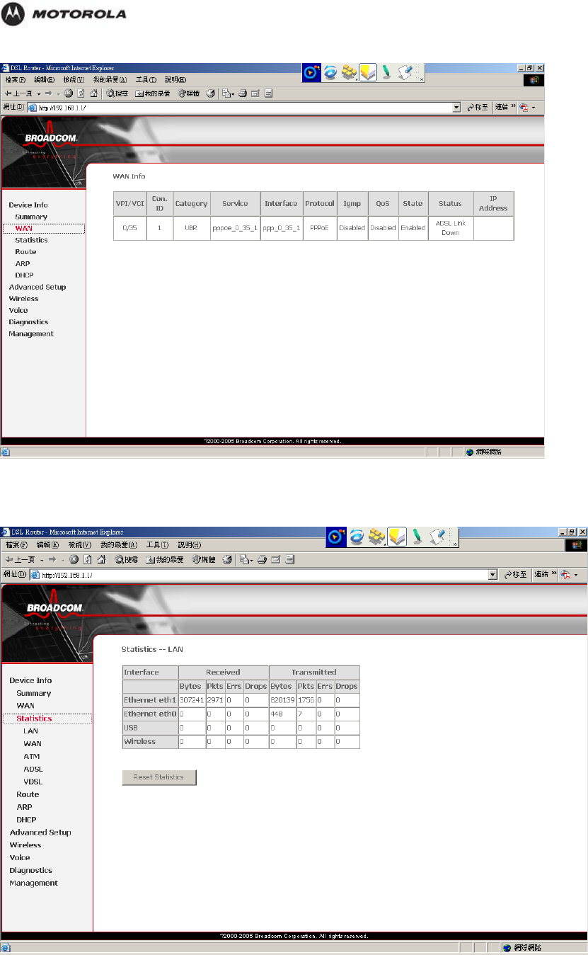
WAN
This page shows the statistics of each PVC on your HH1620.
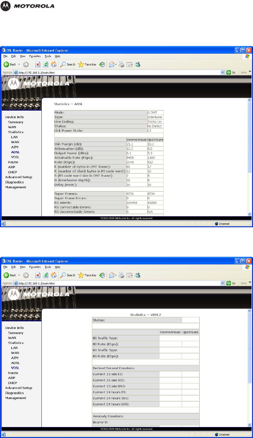
The DSL Status page displays current information on the DSL line performance. The page
refreshes regularly to represent the latest status.
HH1620 Wireless VoIP Gateway
User’s Guide 26
Configuration
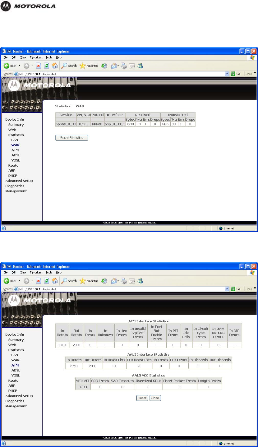
Statistics – LAN
This page shows the statistics of each connection on your LAN.
HH1620 Wireless VoIP Gateway
User’s Guide 27
Configuration
Statistics – WAN
Statistics – ATM
HH1620 Wireless VoIP Gateway
User’s Guide 28
Configuration
Statistics – ADSL
Statistics – VDSL
HH1620 Wireless VoIP Gateway
User’s Guide 29
Configuration
The Advanced Setup Category
It is the
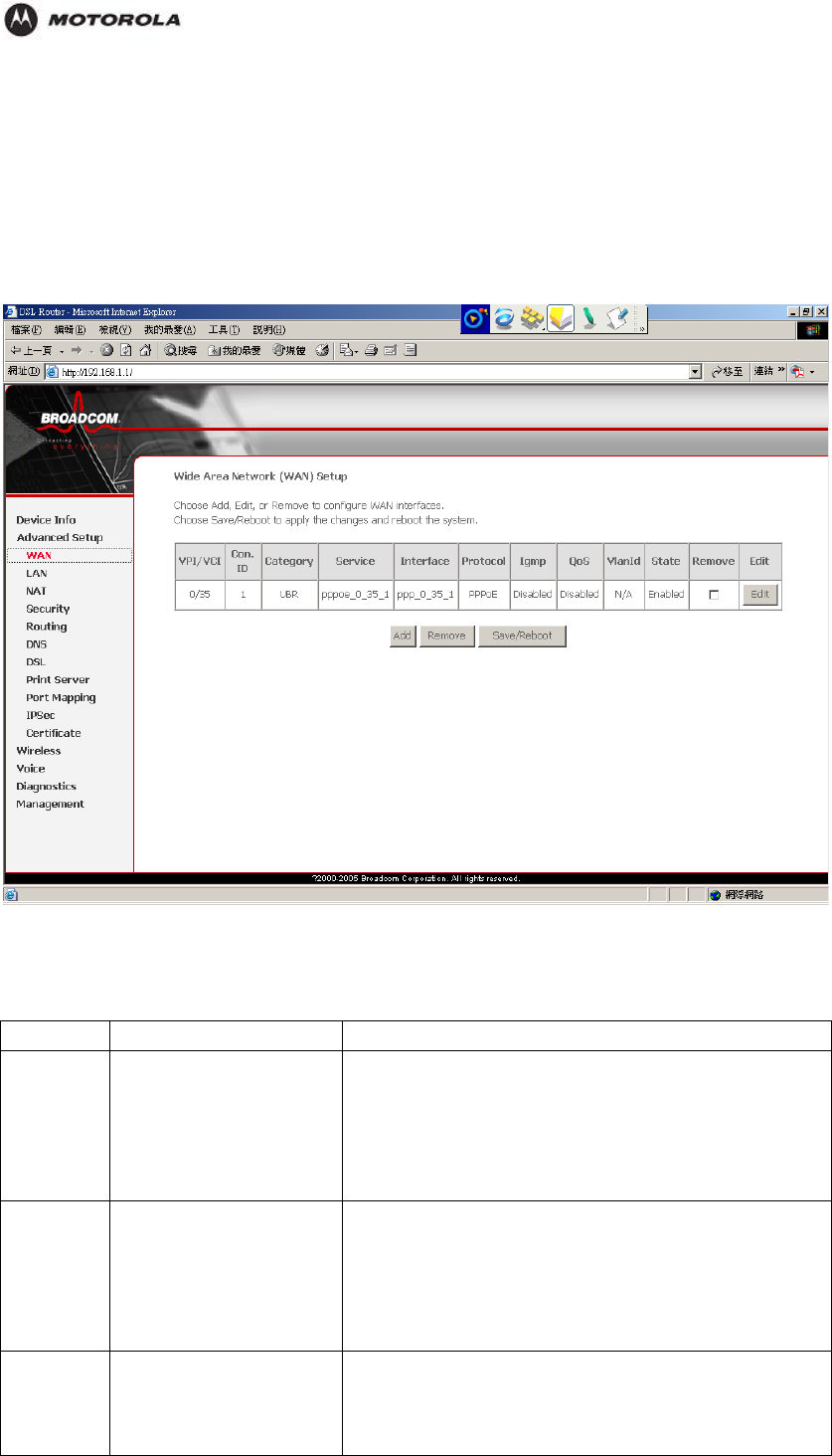
WAN Setup
Yu can click edit to modify an existing WAN interface or tick Remove checkbox and click
Remove button to delete a WAN interface.
Type Details ISP Data required
Dynamic IP
Address Your IP Address is
allocated automatically,
when you connect to you
ISP.
ADSL parameters (VPI and VCI) may be
required, if they cannot be detected
automatically.
Some ISP's may require you to use a particular
Hostname or Domain name, or MAC (physical)
address.
Static
(Fixed) IP
Address
Your ISP allocates a
permanent IP Address to
you. Usually, the
connection is "Always
on".
ADSL parameters (VPI and VCI) may be
required, if they cannot be detected
automatically.
IP Address allocated to you, and related
information, such as Network Mask, Gateway IP
address, and DNS address.
PPPoE,
PPPoA You connect to the ISP
only when required. The
IP address is usually
allocated automatically.
ADSL parameters (VPI and VCI) may be
required, if they cannot be detected
automatically.
User name and password are always required.
HH1620 Wireless VoIP Gateway
User’s Guide 30
Configuration
If using a Static (Fixed) IP address, you need the
IP address and related information (Network
Mask, Gateway IP address, and DNS address)
IPoA (IP
over ATM) Normally, the connection
is "Always on".
ADSL parameters (VPI and VCI) may be
required, if they cannot be detected
automatically.
IP Address allocated to you, and related
information, such as Network Mask, Gateway IP
address, and DNS address.
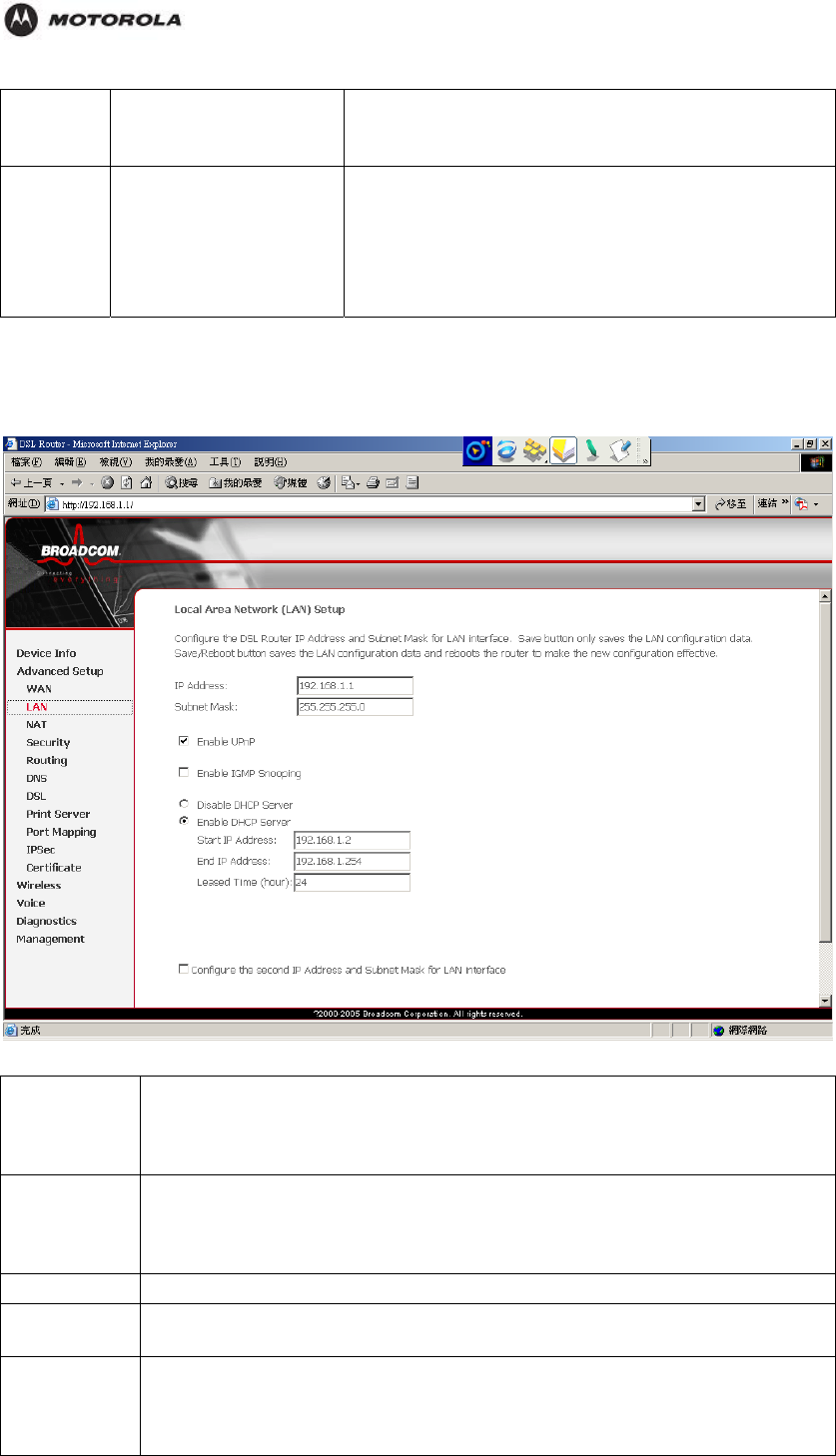
LAN Setup
Configure the DSL Router IP address and Subnet mask for LAN interface.
IP Address IP address for the HH1620, as seen from the local LAN. Use the default value
unless the address is already in use or your LAN is using a different IP
address range. In the latter case, enter an unused IP Address from within the
range used by your LAN.
Subnet Mask The default value 255.255.255.0 is standard for small (class "C") networks.
For other networks, use the Subnet Mask for the LAN segment to which the
IAD-200 / IAD-200W is attached (the same value as the PCs on that LAN
segment).
Enable UPnP
Enable IGMP
Snooping IGMP Snooping provides a dynamic user registration mechanism to decide
whether to multicast packets or not to the specific user in the specified group.
Enable/Disable
DHCP Server
If Enabled, the HH1620 will allocate IP Addresses to PCs (DHCP
clients) on your LAN when they start up. The default (and
recommended) value is Enabled.
If
y
ou are alread
y
usin
g
a DHCP Server, this settin
g
must be Disabled,
HH1620 Wireless VoIP Gateway
User’s Guide 31
Configuration
and the existing DHCP server must be re-configured to treat the
HH1620 as the default Gateway.
The Start IP Address and End IP Address fields set the values used by
the DHCP server when allocating IP Addresses to DHCP clients. This
range also determines the number of DHCP clients supported.
Universal Plug and Play (UPnP) is a distributed, open networking standard that uses TCP/IP
for simple peer-to-peer network connectivity between devices. An UPnP device can
dynamically join a network, obtain an IP address, convey its capabilities and learn about other
devices on the network. In turn, a device can leave a network smoothly and automatically
when it is no longer in use. UPnP-enabled devices may communicate freely with each other
without additional configuration. Disable UPnP if this is not your intention.
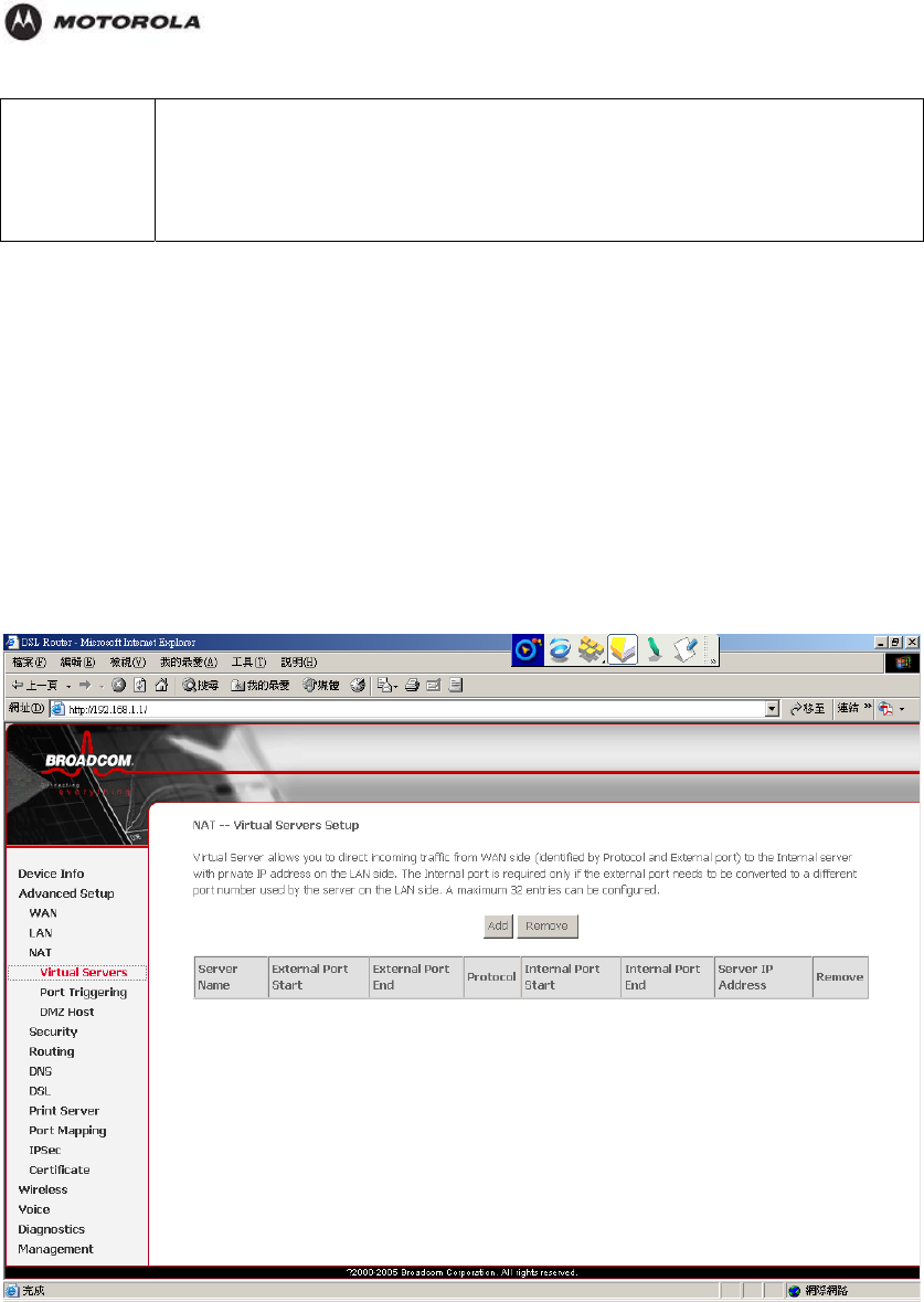
NAT – Virtual Servers
You can configure the HH1620 as a virtual server so that when the remote users accessing
services such as the web of FTP at your local site via public IP addresses can be
automatically redirected to local servers configured with private IP addresses. In other words,
depending on the requested services, the HH1620 redirects the external service request to
the appropriate server (located at another internal IP address).
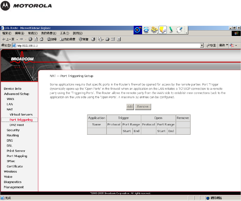
NAT – Port Triggering
Triggers are used to deal with application protocols that create separate sessions. Some
applications, such as NetMeeting, open secondary connections during normal operations, for
example, a connection to a server is established using one port, but data transfers are
performed on a separate connection. A trigger tells the device to expect these secondary
sessions and how to handle them.
Once you set a trigger, the embedded IP address of each incoming packet is replaced by the
correct host address so that NAT can translate packets to the correct destination.
HH1620 Wireless VoIP Gateway
User’s Guide 32
Configuration
NAT – DMZ Host
A DMZ (De-Militarized Zone) is added between a protected network and an external network,
in order to provide an additional layer of security. When there is a suspected packet coming
from WAN, the system will forward this packet to the DMZ host.
You can assign the public IP address of your Internet Connection(s) to a specific device on
your local network. You might want to do this if:
You do not want to use the Network Address Translation engine of your HH1620.
This device is running server applications such as web server and you want it to be
accessible from the Internet.
HH1620 Wireless VoIP Gateway
User’s Guide 33

Configuration
This feature allows the DMZ computer on your LAN to be exposed to all users on the Internet.
If you enable DMZ function, you must configure an IP address of the PC to be used as the
“DMZ Host”.
DMZ Host IP Address: The IP address of the DMZ host viewable at the WAN (external) side.
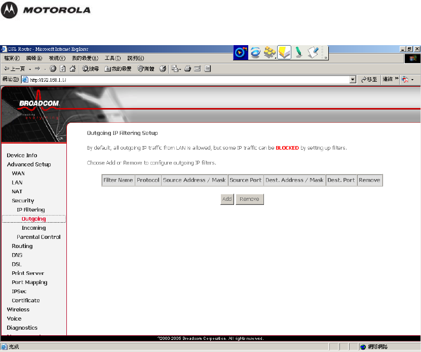
Security – IP Filtering – Outgoing
When you define an outgoing IP filter rule, you instruct the HH1620 to examine the traffics it
sends to determine whether it meets criteria set forth in the rule. If the traffics match the
criteria established in the rule, the traffic will be blocked.
HH1620 Wireless VoIP Gateway
User’s Guide 34
Configuration
HH1620 Wireless VoIP Gateway
User’s Guide 35
Configuration
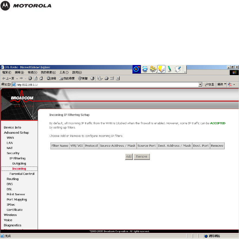
Security – IP Filtering –Incoming
When you define an incoming IP filter rule, you instruct the HH1620 to examine traffics it
receives to determine whether it meets criteria set forth in the rule. If the traffics match the
criteria established in the rule, the traffics can be accepted (forwarded towards its destination).
Security – Parental Control
The Parental Control feature enables management users to block Internet access from
specified LAN hosts for specified periods. Ensure that either the system time is specified
directly or SNTP is enabled.
HH1620 Wireless VoIP Gateway
User’s Guide 36
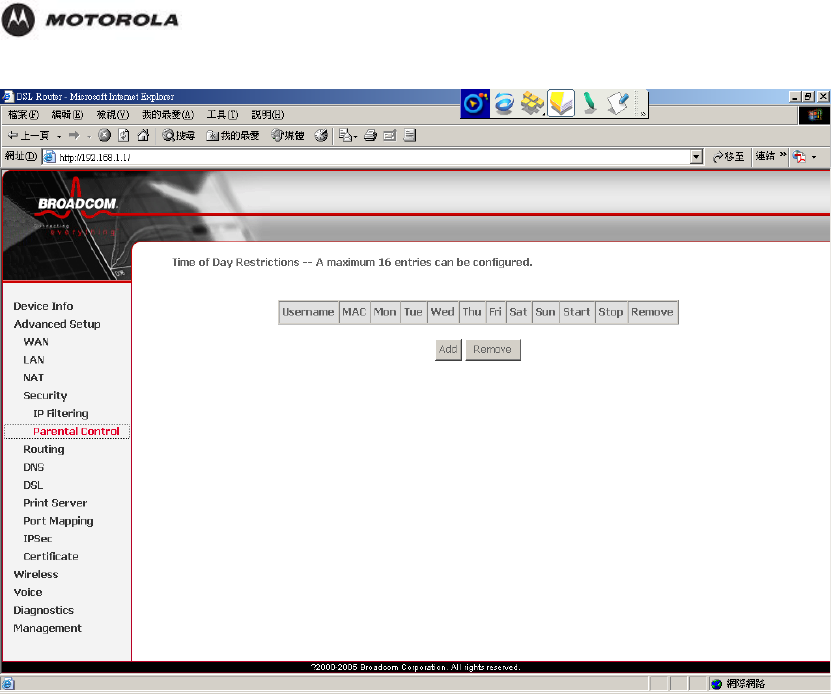
Configuration
For example, if you want to restrict web access to Mon-Fri from 5pm to 11pm, you could
create a schedule selecting Mon, Tue, Wed, Thu, and Fri and enter a Start Time of 5pm and
Stop Time of 11pm.
The parental control rule itself will remain on the system and will be in effect for same time
period each subsequent day until you delete (remove) the rule.
Routing – Default Gateway
HH1620 Wireless VoIP Gateway
User’s Guide 37
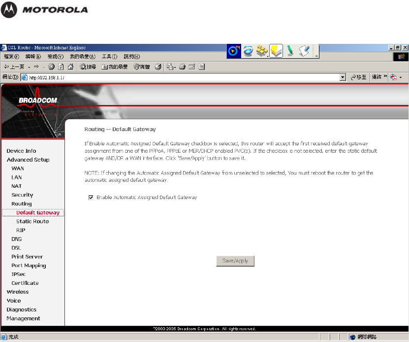
Configuration
Routing – Static Route
Generally, you will use either Static Route or RIP (Routing Information Protocol) although they
can be used simultaneously.
HH1620 Wireless VoIP Gateway
User’s Guide 38

Configuration
Routing – RIP
RIP is an Internet protocol you can set up to share routing table information with other routing
devices on your LAN, at your ISP’s location, or on remote networks connected via the ADSL
line.
HH1620 Wireless VoIP Gateway
User’s Guide 39
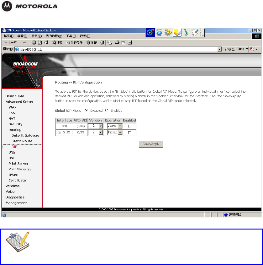
Configuration
Note
In order for the Router to communicate with other devices using RIP, you must
also enable the other devices to use the protocol.
DNS
Domain Name System (DNS) servers map the user-friendly domain names that users type
into their Web browsers (e.g., "www.motorola.com") to the equivalent numerical IP addresses
that are used for Internet routing.
HH1620 Wireless VoIP Gateway
User’s Guide 40

Configuration
DDNS – Dynamic DNS
DDNS is useful when you have a host (running for example, a web server) that receives a
dynamically assigned IP address from a DHCP server. A user on the Internet would typically
access the host by entering its name in their web browser. A DNS server on the web would
then resolve the name to its associated numeric IP address, as required for Internet protocol
processing. However, when a host's IP address is dynamically assigned (for example, by a
DHCP server), it may change frequently. In this scenario, a DNS server may have outdated
data and may not be able to resolve a host name to the current IP address.
When a host is registered with a DDNS service provider, the provider is automatically notified
by the host of any change in its IP address and the provider then propagates the change
throughout the DNS server system.
HH1620 Wireless VoIP Gateway
User’s Guide 41

Configuration
Dynamic DNS (DDNS) is very useful when combined with the Virtual Server feature. It allows
Internet users to connect to your Virtual Servers using a URL, rather than an IP Address.
This also solves the problem of having a dynamic IP address. With a dynamic IP address,
your IP address may change whenever you connect, which makes it difficult to connect to you.
The Dynamic DNS service allows you to assign a dynamic DNS host name (for example
john.dyndns.org) to a broadband connection even if it is using a dynamic IP address. As soon
as the device gets a new IP address, the dynamic DNS server updates its entry to the new IP
address.
On the Configure page, you can assign a Dynamic DNS host name to a broadband
connection. Proceed as follows:
1. Click Add.
2. Create an account at the Dynamic DNS service of your choice, for example:
www.dyndns.org
www.no-ip.com
www.dtdns.com
3. Type the user name and password of your Dynamic DNS service account in the
corresponding fields.
4. If necessary, click the broadband connection to which you want to assign the Dynamic
DNS hostname in the Interface list.
5. In the Service list, click your Dynamic DNS service.
In the Host box, type the host
6. name you want to assign to this interface (for example
myspeedtouch.dyndns.org).
HH1620 Wireless VoIP Gateway
User’s Guide 42
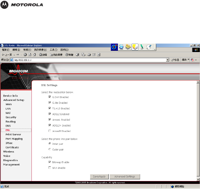
Configuration
DSL
Select the modulation types, line pair and capability that you want the HH1620 to support.
Multi-Mode standard (ANSI T1.413, Issue 2; G.dmt (G.992.1); G.lite (G992.2))
EOC specified in ITU-T G.992.1
ADSL2 G.dmt.bis (G.992.3)
ADSL2 G.lite.bis (G.992.4)
AnnexL: Annex L, also known as Reach Extended ADSL, extends DSL line reach, making it
possible for Telcos to offer DSL service to subscribers who are more than 18,000 feet from
the CO (central office).
ADSL2+ (G.992.5)
SRA (Seamless Rate Adaptation): SRA makes dynamic data transfer rate changes to
accommodate temporary noise conditions on the line thus preventing dropped connections.
AnnexM: Annex M doubles upstream data rates. With this new feature, Telcos can create and
offer business subscribers an approximately 2.5 Mbps symmetrical data service providing
with businesses a low-cost alternative to T1 or G.SHSDL data services.
Printer Server
HH1620 includes an integrated printer server that allows a printer shared between multi
computers on your LAN. USB port to connect to a USB printer and includes a Windows-based
print server software application, so users on the network can share the printer. The print
server is also capable of TCP/IP printing.
HH1620 Wireless VoIP Gateway
User’s Guide 43
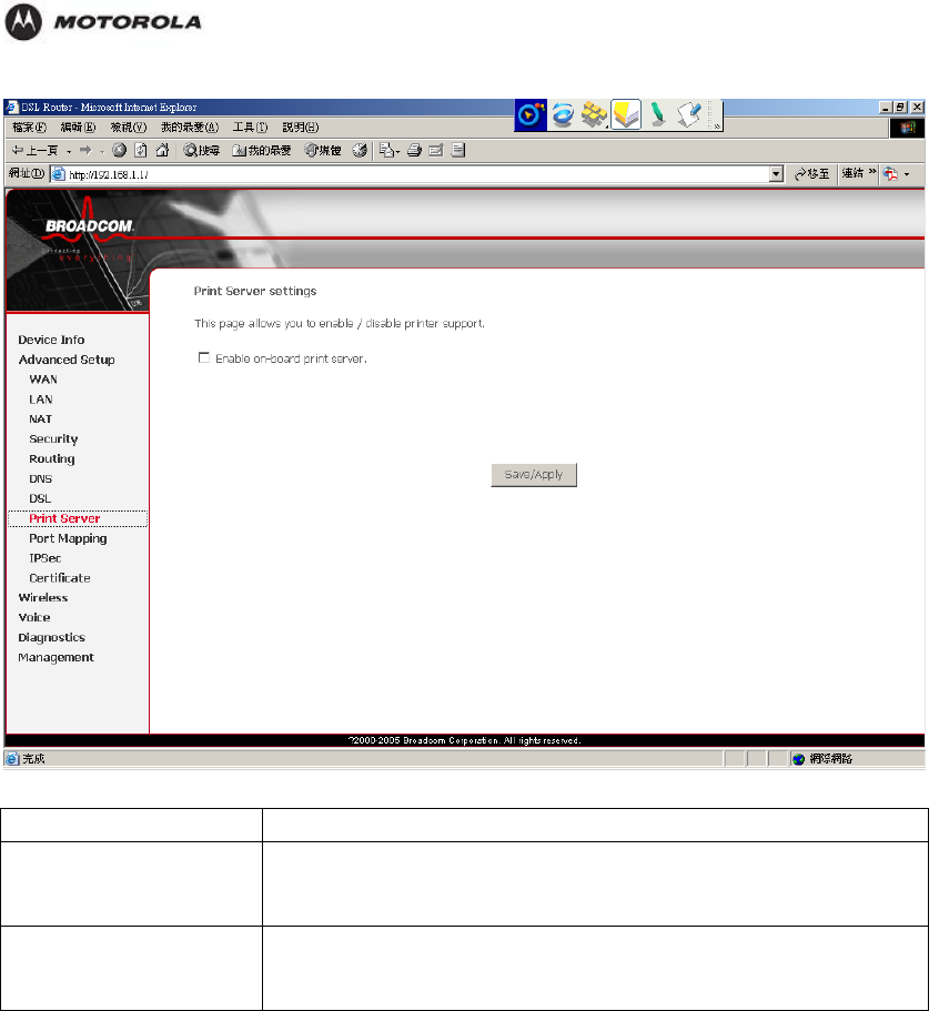
Configuration
Printer Status Shows the status of the printer attached to the router.
Raw TCP Port Printing Shows the “IP Address” and “TCP Port” values that you need to
enter when you configure your computer to use the printer in TCP
Raw mode.
LPD/LPR Printing Shows the “IP Address” and “Queue Name” values that you need
to enter when you configure your computer to use the printer in
LPR/LPD mode.
HH1620 Wireless VoIP Gateway
User’s Guide 44
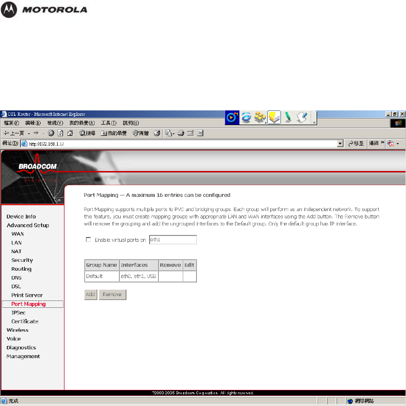
Configuration
Port Mapping
Port Mapping supports multiple ports to PVC and bridging groups. Each group will perform as
an independent network. You must create mapping groups with appropriate LAN and WAN
interfaces before you can use this feature.
IPSec
Internet Protocol Security (IPSec) is a standards-based VPN that offers flexible solutions for
secure data communications across a public network like the Internet. IPSec is built around a
number of standardized cryptographic techniques to provide confidentiality, data integrity and
authentication at the IP layer.
HH1620 Wireless VoIP Gateway
User’s Guide 45
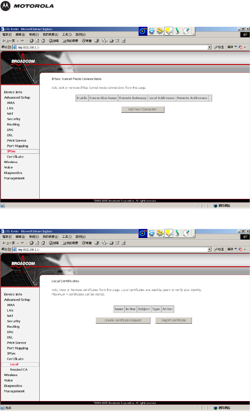
Configuration
Certificate – Local
HH1620 Wireless VoIP Gateway
User’s Guide 46
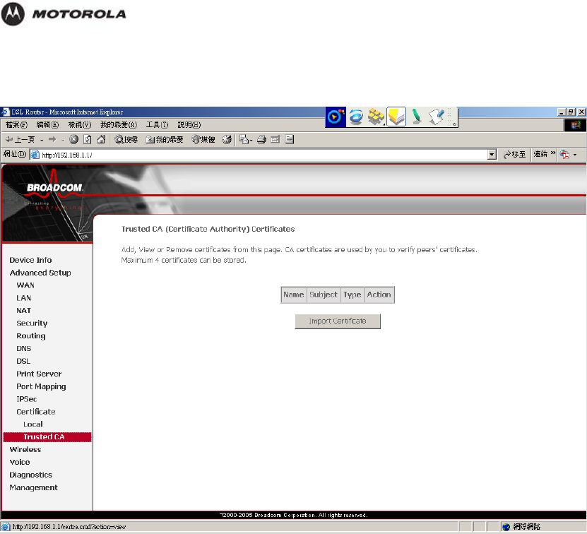
Configuration
Certificate – Trust CA
HH1620 Wireless VoIP Gateway
User’s Guide 47
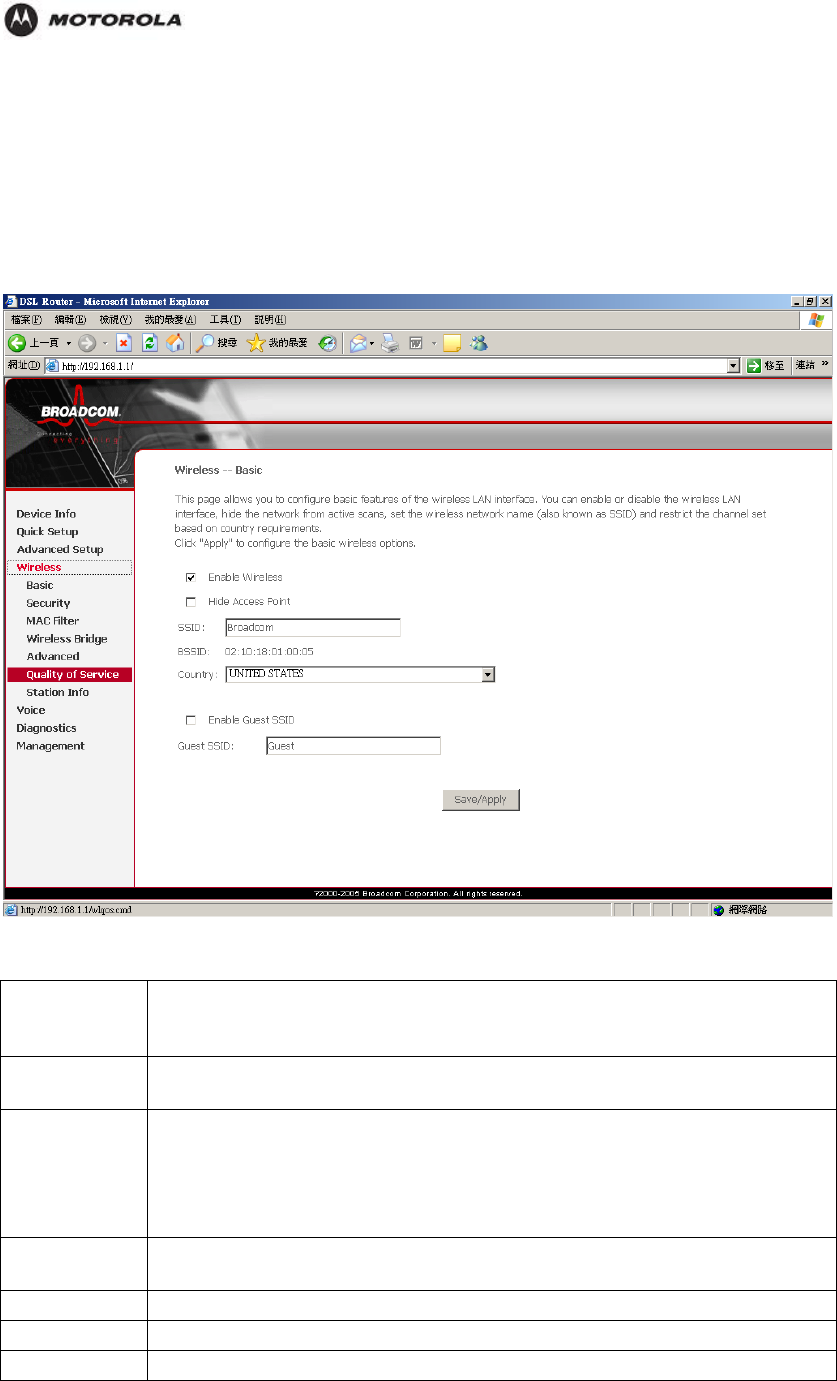
Configuration
The Wireless Category
Basic
This page allows you to configure features of the wireless LAN interface. You can
enable/disable wireless LAN interface, hide the network from activate scans, set wireless
network name and restrict the channel set based on country requirements.
Enable Enable this if your want to use Wireless Access Point function. If not tick, no
wireless stations can use the wireless function, and all connections must be
made via the wired LAN.
Hide Access
Point Select Hide to hide the SSID in so a station cannot obtain the SSID through
scanning.
SSID The SSID (Service Set IDentification) is a unique name to identify the
HH1620 in the wireless LAN. Wireless stations associating to the HH1620
must have the same SSID.
Enter a descriptive name of up to 32 printable characters (including spaces,
alphabetic characters are case-sensitive).
BSSID The BSSID (Basic Service Set Identifier) is the MAC address of the wireless
station in an Access Point (AP) in an infrastructure mode BSS.
Country
Guest SSID
Restrict
HH1620 Wireless VoIP Gateway
User’s Guide 48
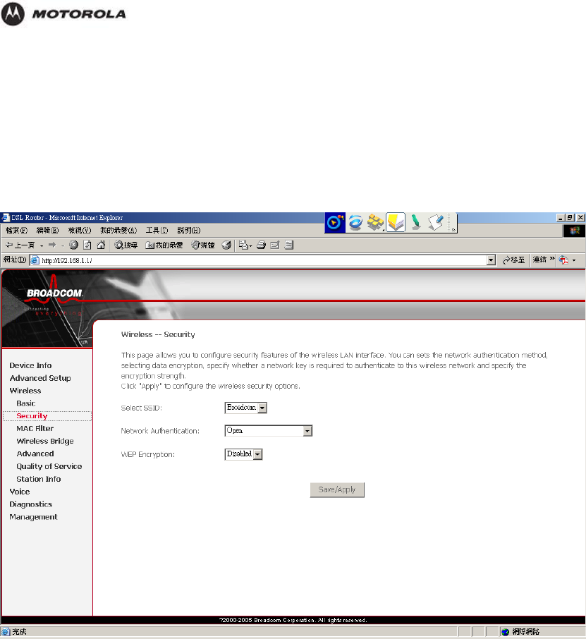
Configuration
Security
WEP encryption scrambles the data transmitted between the wireless stations and the access
points to keep network communications private. It encrypts unicast and multicast
communications in a network. Both the wireless stations and the access points must use the
same WEP key.
The HH1620 allows you to configure up to four 64-bit, 128-bit or 256-bit WEP keys but only
one key can be enabled at any one time.
The SSID (Service Set IDentification) is a unique name to identify the HH1620 in the wireless
LAN. Wireless stations associating to the HH1620 must have the same SSID. Enter a
descriptive name of up to 32 characters (including spaces; alphabetic characters are case-
sensitive).
WEP (Wired Equivalent Privacy) encrypts data frames before transmitting over the wireless
network.
Select Disable to allow all wireless stations to communicate with the access points without
any data encryption. Or, select 64-bit WEP, 128-bit WEP or 256-bit WEP to use data
encryption.
64-bit WEP: Enter 5 characters or 10 hexadecimal digits (0-9 and A-F).
128-bit WEP: Enter 13 characters or 26 hexadecimal digits (0-9 and A-F).
256-bit WEP: Enter 29 characters or 58 hexadecimal digits (0-9 and A-F).
HH1620 Wireless VoIP Gateway
User’s Guide 49
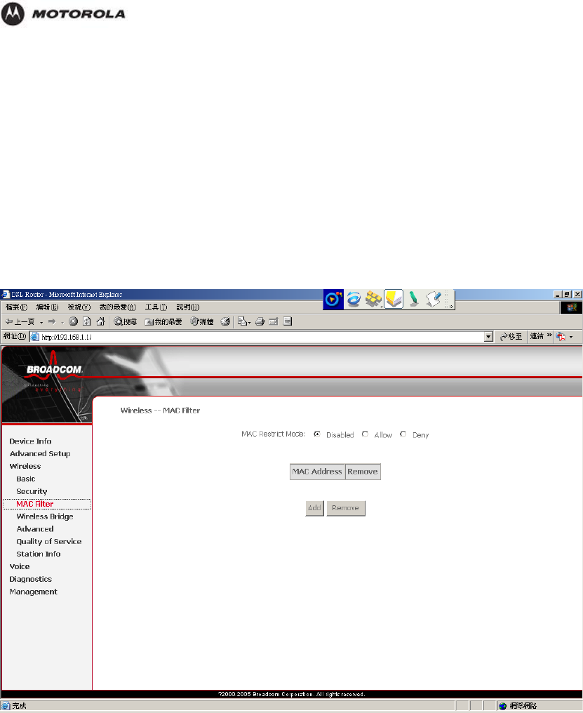
Configuration
MAC Filter
MAC address filtering means sifting traffic going through the HH1620 based on the source
and/or destination MAC addresses.
Every Ethernet device has a unique MAC (Media Access Control) address. The MAC address
is assigned at the factory and consists of six pairs of hexadecimal characters, for example,
00:A0:C5:00:00:04. You need to know the MAC addresses of the devices to configure this
page.
You can configure the HH1620 to give exclusive access to devices (Allow Association) or
exclude them from accessing the HH1620 (Deny Association).
HH1620 Wireless VoIP Gateway
User’s Guide 50
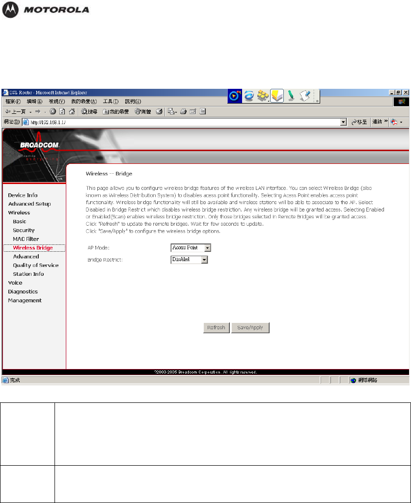
Configuration
Wireless Bridge
This page allows you to configure wireless bridge feature of the wireless LAN interface.
AP Mode Wireless Bridge (Wireless Distribution System): This mode allows you to disable
access point functionality.
Access Point: This mode allows you to enable access point functionality, and
wireless bridge functionality will still be available and wireless stations will be
able to associate to the AP.
Bridge
Restrict This selection allows you to enable/disable the wireless bridge restriction. If
disabled, any wireless bridge will e granted access. Only those bridges selected
in Remote Bridges will be granted access.
HH1620 Wireless VoIP Gateway
User’s Guide 51
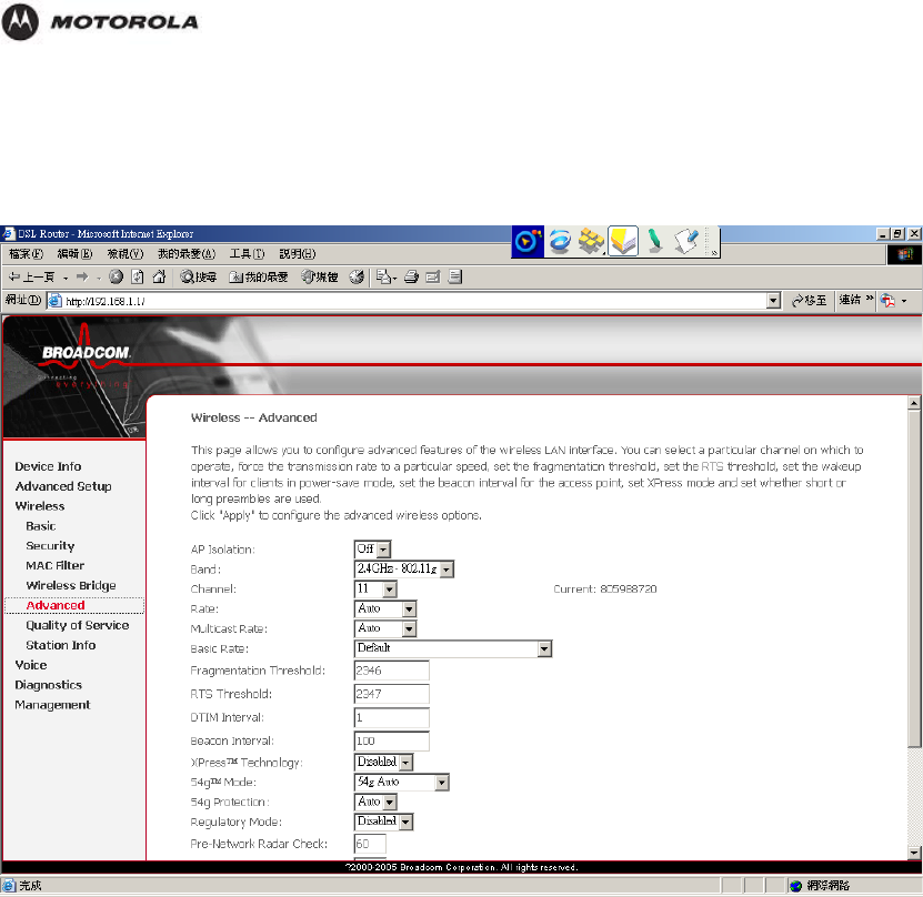
Configuration
Advanced
This page allows you to configure advanced features of the wireless LAN interface, including
channel, transmission rate fragmentation threshold, beacon interval and so on.
The Xpress Technology is one of the popular performance-enhancing WiFi technologies,
designed to improve wireless network efficiency and boost throughput. It is more efficient in
mixed environments, and it can work with 802.11a/b/g networks.
When Xpress is turned on, aggregate throughput (the sum of the individual throughput
speeds of each client on the network) can improve by up to 27% in 802.11g-only networks,
and up to 75% in mixed networks comprised of 802.11g and 802.11b standard equipment.
The technology achieves higher throughput by re-packaging data, reducing the number of
overhead control packets, so that more useful data can be sent during a given amount of time.
54g
54g® is Broadcom's Wi-Fi chipset designed for maximum performance IEEE 802.11g
wireless networks. 54g® is found in leading brands of high-performance wireless products
that deliver greater speed, improved reach, and the latest, toughest security that is configured
with the push of a button.
Quality of Service
Quality of Service (QoS) referrs to both a network’s ability to deliver data with minimum delay,
and the networking methods used to pvovide bandwidth for real-time multimedia applications.
HH1620 Wireless VoIP Gateway
User’s Guide 52
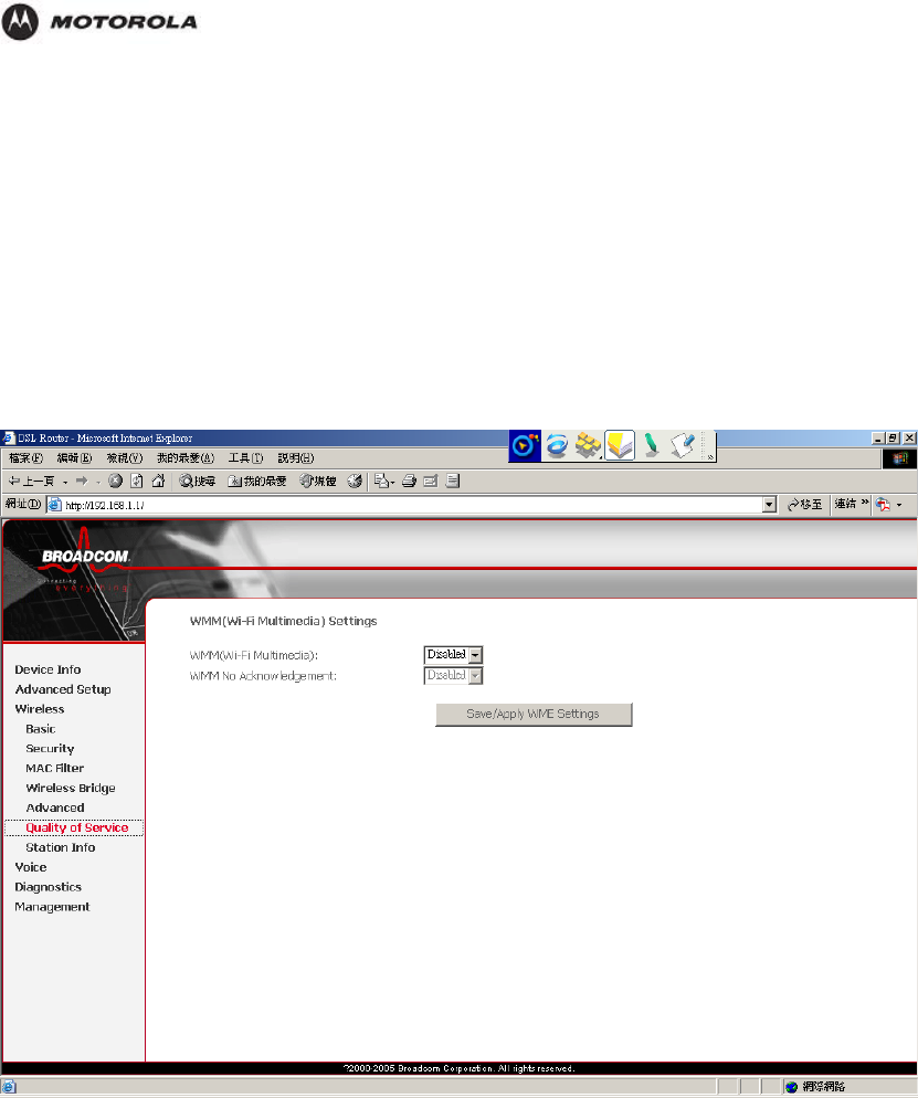
Configuration
WMM is designed to support consumer and corporate applications and works with all three
802.11 wireless physical layer standards - 802.11a, 802.11b and 802.11g. The specification
provides basic prioritization of data packets based on four categories - voice, video, best
effort and background.
Select to enable or displays WMM. WMM (Wi-Fi MultiMedia) enhances QoS at wireless driver
level. It provides a mechanism to prioritise wireless data traffic to and from the associated
(WMM capable) stations.
If your enable WMM feature, you may need to decide whether to broadcast HH1620’s
network name or not. Broadcasting allows you to easily recognize your wireless network in
the list of available networks. Once you have configured your wireless clients, it is
recommended to disable this feature.
HH1620 Wireless VoIP Gateway
User’s Guide 53
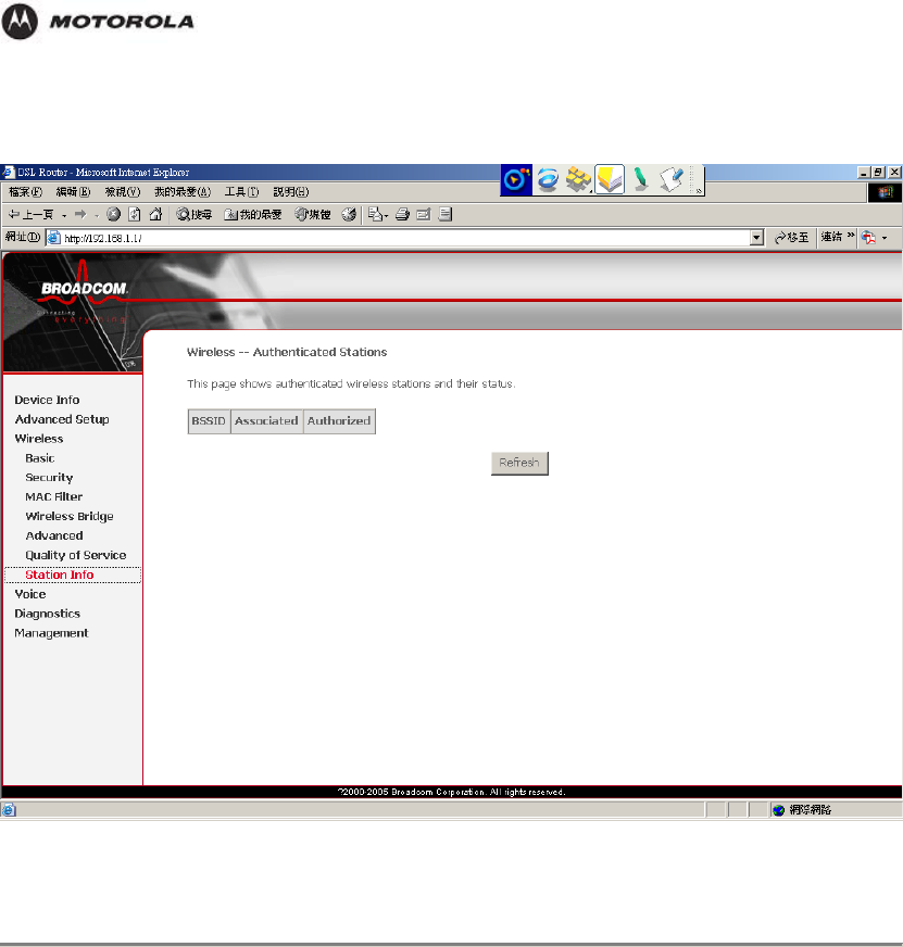
Configuration
Station Info
This page shows authenticated wireless stations and their status.
The Voice Category
voice sip 的preferred ptime
Internet telephony or Voice over IP (VoIP) can be defined as the transfer of telephone calls
over your Internet connection.
You can make Internet and PSTN telephone calls using tradition analogue phones connected
to your HH1620. HH1620 provides additional lines without the need for additional copper
pairs. It allows you to make and receive calls simultaneously.
HH1620 Wireless VoIP Gateway
User’s Guide 54
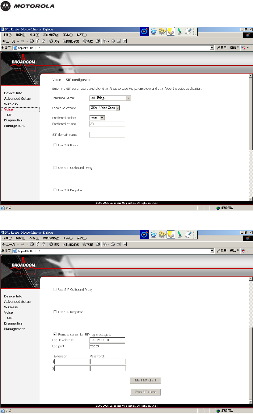
Configuration
Select the Codec that is more suitable than the other Codecs.
HH1620 Wireless VoIP Gateway
User’s Guide 55

Configuration
You can also connect a fax machine to your HH1620 to send and receive faxes over your
Internet connection or the PSTN phone line.
Your ISP should provide you with the following SIP configuration parameters:
Uniform Resource Identifier (URI)
User name
Password
IP address and port number (usually 5060) of the provider’s registrar
IP address and port number (usually 5060) of the provider’s SIP proxy server
The SIP URI is a unique name used to identify and locate your telephone. The SIP URI can
have a numerical format or the format user@host.
Example:
1234567
username@hostname.org
username@192.168.10.1
1234567@hostname.org
If your ISP gives you an URI in the format containing an ‘@’, your ISP will tell you whether the
‘@’ can be formed on your phone by dialing ‘1’, ‘*’ or ‘#’.
Connect TEL port(s) to your phone(s) or fax.
If you want to make phone calls using the regular telephone line. Connect PSTN port to the
telephone output of your DSL splitter or the telephone wall outlet to allow regular phone calls
with the dame telephone set.
Configure Internet Telephony
Enable the telephony service
Assign phone numbers
Configure the telephony service
Enter the Registrar Server address to register end point.
Enter the Registrar port number that is between 1024 and 32768. By default, it is 5060.
HH1620 Wireless VoIP Gateway
User’s Guide 56
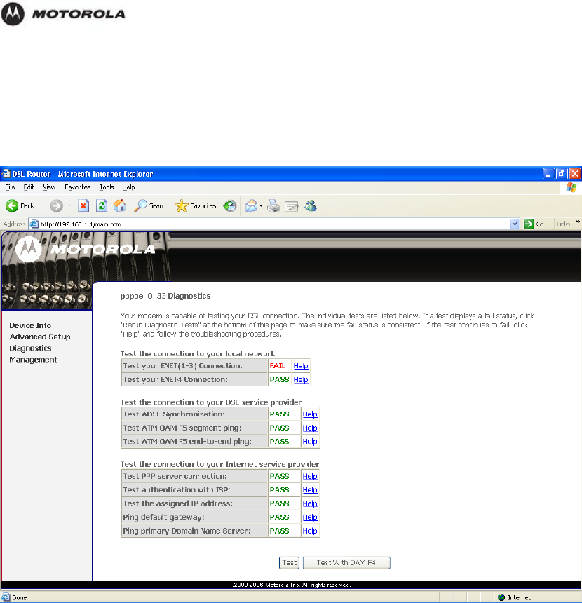
Configuration
The Diagnostics Category
This feature allows you to perform a series of testing. This activity can be useful in solving
network problems.
HH1620 Wireless VoIP Gateway
User’s Guide 57
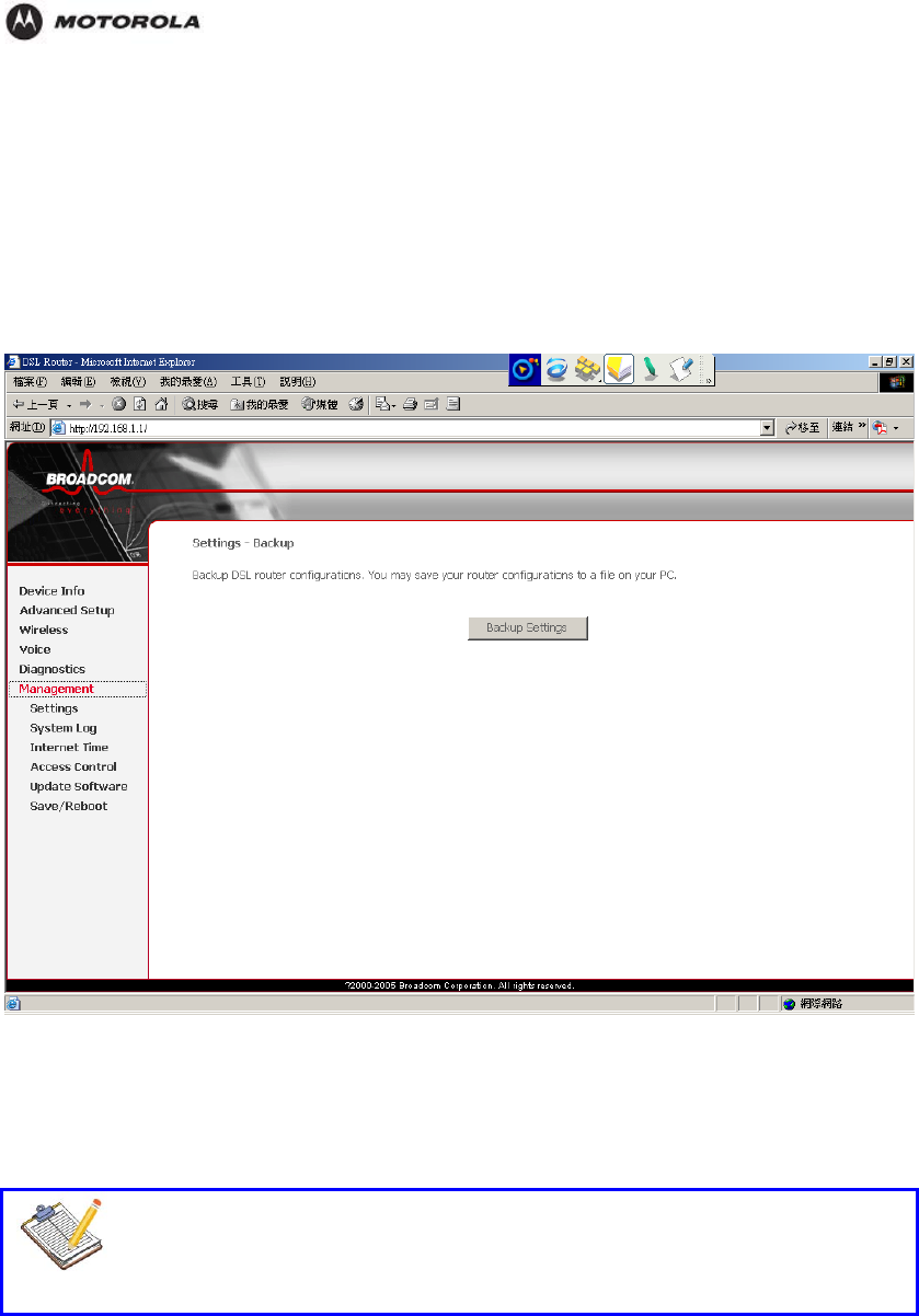
Configuration
The Management Category
Settings – Backup
This page allows you to backup the HH1620's current settings.
Once you have the HH1620 working properly, you should backup the information to have it
available if something goes wrong. When you backup the settings, they are saved as a file on
your computer. You can restore the settings from this file.
To create a backup file of the current settings:
1. Click Backup Settings Button.
2. Locate where you want to save the file, rename it if you like, and click OK.
Note
DO NOT power off the HH1620 while processing. Restart the HH1620 after the
upgrade is complete. Your previous configuration will be lost and you need to re-
configure the settings.
HH1620 Wireless VoIP Gateway
User’s Guide 58
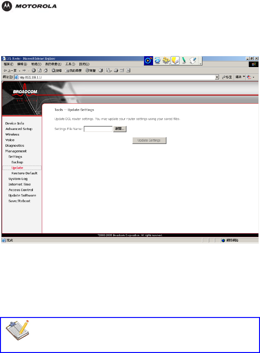
Configuration
Settings – Update
Use this to download a copy of the current configuration, and store the file on your PC.
To perform the Update process:
1. Click Browse button and indicate the location of the update DSL setting file.
2. Click Update Settings button to commence the setting update.
3. Wait about 2 minutes for the process to be completed and reboot the HH1620. A
window appears letting you know that the HH1620 has been successfully restored to
previous settings.
Note
DO NOT power off the HH1620 while processing. Restart the HH1620 after the
upgrade is complete. Your previous configuration will be lost and you need to re-
configure the settings.
HH1620 Wireless VoIP Gateway
User’s Guide 59
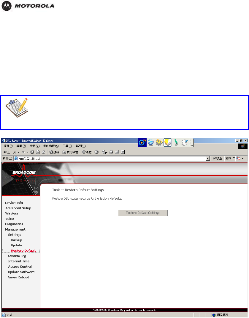
Configuration
Settings – Restore Default
You might consider a reset to factory defaults as described below.
You can choose between:
Software reset
Hardware reset
A reset to factory default settings deletes the configuration profile settings. Therefore, after
the reset, a reconfiguration of your HH1620 will be needed.
Note
Be aware that a reset to factory defaults will reset all configuration you made to
the HH1620.
Software Reset
1. Make sure that you need to reset all configurations to default and click Reset Default
Settings button.
2. Wait for the HH1620 reset to default settings and return to its home page.
3. You need to re-configure your settings to reform the all the connections.
Hardware Reset
1. Make sure the HH1620 is turned on.
2. Use a pen or an unfolded paperclip to push the recessed reset button on the back pane
The reset button is marked with a red l.
circle. Push it until the power LED lights red - this
will take about 7 seconds.
3. Release the reset button.
HH1620 Wireless VoIP Gateway
User’s Guide 60
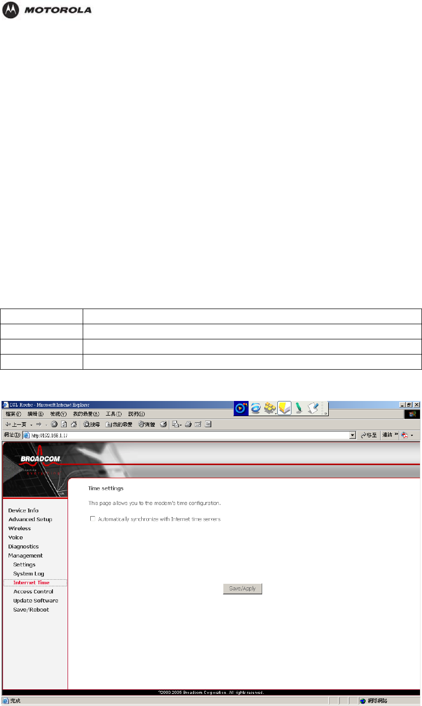
Configuration
. You need to re-configure your settings to reform the all the connections.
an also be E-
ailed to you PC. Click Configure System Log button to configure this feature.
nfigure system log page allows you to configure the events shown in the System Log
ble.
e d.
4. The HH1620 restarts.
5
System Log
The System Logs page records various types of activity on the HH1620. This data is useful
for troubleshooting, but enabling all logs will generate a large amount of data and adversely
affect performance.
You can view data generated or acquired by routine system communication with other
devices, such as the results of negotiations with the ISP’s computers for DNS and gateway IP
addresses.
Since only a limited amount of log data can be stored in the HH1620, log data c
m
The System Log table gives you an overview of the last event logs that have been recorded
since the HH1620 was turned on.
The Co
ta
Current Tim The current time on the HH1620 is displaye
Log Data urrent log data is displayed in this panel. C
Internet Time
HH1620 Wireless VoIP Gateway
User’s Guide 61
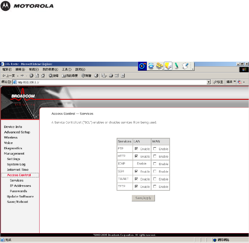
Configuration
Tick the button to user the default Internet time server to get
the time from Internet.
Access Control – Services
HH1620 Wireless VoIP Gateway
User’s Guide 62
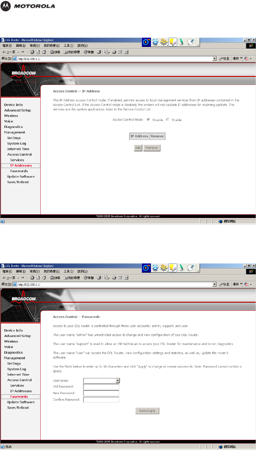
Configuration
Access Control – IP Addresses
Access Control – Passwords
On this page you can change the default user.
HH1620 Wireless VoIP Gateway
User’s Guide 63
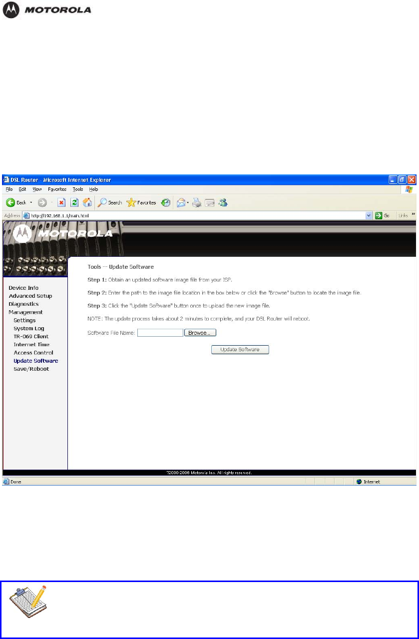
Configuration
1. Select the username from the drop-down list to change it password.
2. Type the old password, new password and confirm (re-type) password.
3. Click Save/Apply to confirm your choice.
Update Software
The firmware (software) in the HH1620 can be upgraded by using your web browser.
You must first download the upgrade file to you local hard drive, then proceed the update
process.
To perform the Update process:
1. Click Browse button and indicate the location of the upgrade file.
2. Click Update Software button to commence the firmware upgrade.
3. Wait about 2 minutes for the process to be completed and reboot the HH1620.
Note
DO NOT power off the HH1620 while processing. Improper operation could
damage the Gateway. The HH1620 will restart automatically after the upgrade is
complete. Your previous configuration will be lost and you need to re-configure
the settings.
HH1620 Wireless VoIP Gateway
User’s Guide 64
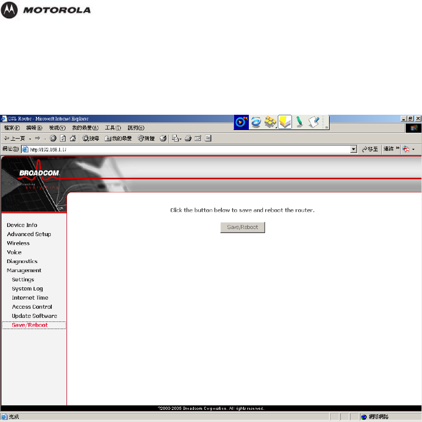
Configuration
Save/Reboot
After changing the HH1620’s configuration settings, you must save all of the configuration
parameters to FLASH to avoid them being lost after turning off or resetting your HH1620.
Click Save/Reboot to write your new configuration to FLASH.
HH1620 Wireless VoIP Gateway
User’s Guide 65

Troubleshooting
4. Troubleshooting
This section details possible solutions to common problems that might occur in using the
router.
Contact Us
If you are unable to locate a solution here, please access our website at
http://www.motorola.com/homenetworking for the latest information. You can also reach us 7
days a week, 24 hours a day at 1-877-466-8646.
My HH1620 does not work.
If none of the LEDs light up, make sure that:
The HH1620 is plugged into a power socket outlet.
You are using the correct power supply for your HH1620 device.
The HH1620 is turned on via the push button at the back panel.
Note: The power requirements for your HH1620 are clearly indicated on the
identification label on the bottom of the HH1620.
If the LAN LED does not light up, make sure that:
The LAN cable is securely connected to the 10/100Base-T port.
You are using the correct cable type for your Ethernet equipment, that is UTP CAT5 with
RJ-45 connectors.
My computer is experiencing difficulty connecting to the wireless network.
Ensure that your router is powered on and that the Wireless LED is on.
Ensure that your wireless adapter (PCI card, Notebook or Ethernet adapter) is installed
correctly and is active.
Ensure that your wireless adapter’s radio signal is enabled. Review your adapter’s
documentation for further instructions.
Ensure that your wireless adapter for your PC and the wireless router have the same
security settings that will allow your computer to access the wireless network. Also,
verify that the list of Restricted Wireless MAC Addresses (on the WIRELESS Page of
the Web-based Configuration Utility is not configured to block your PC.
Ensure that your wireless adapter is within range of your router or is not behind an
obstruction. For example, metal structures will interfere with the signal, as will 2.4 GHz
cordless phones, and microwaves.
Ensure that your router’s antenna is connected and that your PC’s wireless adapter
antenna is also connected.
My computer is experiencing difficulty in connecting to the router.
Ensure that all of your cabling connections are firmly connected. This includes the
cables from the wall to your modem, between the router and modem, and, if available,
from the router to your PC.
Ensure that your LEDs are not lit Red or not at all. For further information about LED
descriptions, see Section 1: Overview.
Ensure that you are using Ethernet cables and not telephone cables between the router
and modem or router and PC. See the illustration below. Ethernet cables use a wider
RJ-45 style plug using 8 wires where telephone style plugs use the smaller RJ-11 style
plug using 4 to 6 wires.
HH1620 Wireless VoIP Gateway
User’s Guide 66
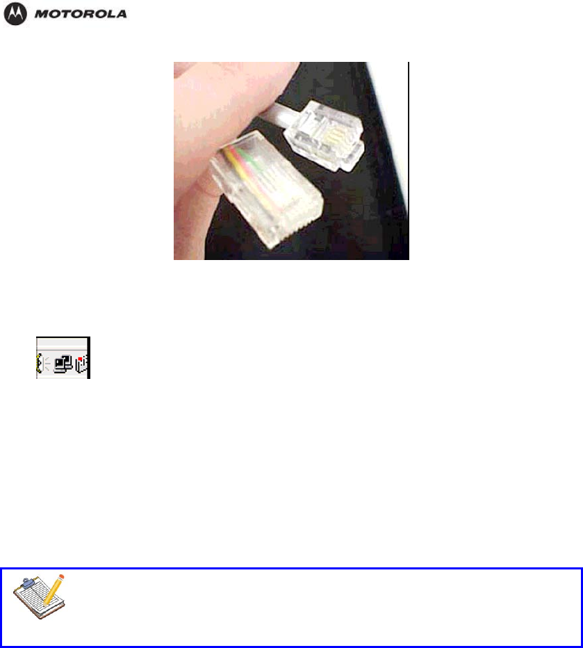
Troubleshooting
The plug on the left is RJ-45; the plug on the right is RJ-11 – use only RJ-45.
Ensure that your Ethernet adapter is enabled. To check the status of your adapter, click
the monitor icon in the System Tray at the bottom right of your screen.
You can also check the status of the Ethernet adapter by selecting Control Panel >
Network and Dial-Up Connections.
My broadband modem already uses a built-in router.
Because the two routers will cancel each other out, turn off the NAT function in the modem to
enable access for your router. Refer to your modem’s documentation for further instructions.
I can login to HH1620.
If your HH1620 is cannot be reached due to misconfiguration, you might consider a hardware
reset to factory defaults as described in section 1.2.3.
Note
However, note that resetting the HH1620 to its factory settings will revoke all the
changes you made to the configuration.
The performance of HH1620 is poor.
Make sure that the HH1620 is installed and configured as instructed in the Installation and
Setup Guide or as instructed by the Service Provider.
The wireless performance of HH1620 is poor.
Choose automatic channel selection or carefully select a radio channel that does not interfere
with other radio channels.
Make sure both the WLAN client adapter and the HH1620 are allowed to connect through
wireless channels as defined for local regulatory domain.
Check the location of the HH1620 in the building.
Check the signal strength, indicated by the wireless client manager. If the signal is low, try to
place the HH1620 or to direct the HH1620’s antenna for optimal performance.
HH1620 Wireless VoIP Gateway
User’s Guide 67

Troubleshooting
I would like to test to see if my Internet connection is live.
Use the ping command to test the connection. Before attempting, ensure that Obtain an IP
address automatically has been selected in the computer’s settings and that you have an IP
address assigned. Refer to Configure Your Computers in Section 2: Installation, for further
details.
1. Open a command prompt by clicking Start and Run.
2. For Windows 98 and ME, in the Open field, type command and press Enter or OK.
For Windows 2000 and XP, type cmd. Or, navigate using your Start button to
Programs>Accessories>Command Prompt.
3. In the Command window, type ipconfig.
You should see an IP address for your network adapter:
Ethernet Adapter Local Area Connection:
Connection-specific DNS Suffix: Example.example.example.com.
IP Address. . . . . . . . . . . . : 192.168.110
Subnet Mask . . . . . . . . . . . : 255.255.255.0
Default Gateway . . . . . . . . . : 192.168.11
4. he s Enter. In t Command window, type ping followed by the Router’s IP address and pres
If you receive a reply (the first word will be Reply…), then your computer is
connected to the router. Proceed to Step 4.
If you do NOT receive a reply, repeat steps 1 – 4 on a different computer to verify
that the first computer is not the cause of the problem.
Your computer’s Default Gateway’s IP address may also be your router’s IP
address.
Verify the router’s IP address by logging on to the router’s Web-based
Configuration Utility and reviewing the IP Address field on the LAN Page.
In the C
5. ommand window, type ping followed by your ISP’s default gateway and press
e: Reply from 216.109.125.72…), then your
sed
ifferent computer to verify
on Utility for the router.
he IP address for your PC, refer to Configure Your Computers
r, you will
.1.
Username, Password, IP Address, and Subnet mask.
Enter.
If you receive a reply (For exampl
connection to the Internet is live.
To verify the ISP default gateway’s IP address, log on to the router’s Web-ba
Configuration Utility and verify the Default Gateway field on the WAN Page.
If you do NOT receive a reply, repeat steps 1 - 5 on a d
that the first computer is not the cause of the problem.
I cannot access the Web-based Configurati
Verify your Ethernet connection to the router.
Verify that the IP address of the PC being used to configure the router is on the same
network as the router’s configuration IP address.
The IP address of your network adapter must be on the same network and not a
duplicate of any others on the network (for example: 192.168.10.10 and using a subnet
mask of 255.255.255.0 can be used to login to the router’s default IP address of
192.168.10.1). To adjust t
in Section 2: Installation.
Verify that you can ping the router on this IP address.
nter.
In the Command window, type ping and your router’s default IP address and press E
If you have changed the factory configured default IP address of the route
need to set your network adapter accordingly.
Verify you are entering the correct URL in the browser. The default is http://192.168.10
If you think you have changed the IP address used to configure the router and cannot
remember it, you must reset the unit back to factory defaults. To do this, press and hold
the reset button for more the 5 seconds. This clears the router’s user settings, including
HH1620 Wireless VoIP Gateway
User’s Guide 68
Troubleshooting
Once the router is reset to factory default, re-verify the Ethernet connectivity and IP
address issues.
How do I extend my wireless network to cover more area?
You need more than one access point with WDS (Wireless Distribution System) enabled to
expand your wireless network. For example, if you are running HH1620, you will need another
wireless Access Point (AP), most likely a WA840G or WA840GP (but you can use another
HH1620; just ensure that you do not run two DHCP servers at the same time).
Set up both the HH1620 and the WA840 with the same wireless SSID, the same channel
number, and the same WPA Pass Phrase or WEP keys. It is suggested that you also enable
the Wireless Bridge Restriction Mode to limit the exposure of your wireless network to outside
users. The wireless MAC address of the other AP needs to be added to each AP’s list of
Recognized Bridges, that is, the WA840’s wireless MAC address needs to be in the HH1620’s
list of Recognized Bridges, and vice versa.
Once enabled, your laptop can now roam between the two APs, thereby extending your
wireless network.
I cannot browse past the first screen of the Web-based Configuration Utility.
Sometimes, especially when upgrading, some leftover files may be in your Internet Cache.
Flush your cache and restart your unit to fix. From Internet Explorer’s menu, select Tools >
Options and click Delete Files to clear your cache.
How do I match WEP keys between the router and my wireless clients?
Some wireless cards do not support WPA, and in turn cannot accept a WPA Pass Phrase.
For compatibility with these clients, WEP Encryption must be enabled on the SECURITY
Page of the Web-based Configuration Utility, with at least one WEP Network Key entered.
Using the utility provided with your wireless client, you must enter the same key that is
entered in the HH1620. If more than one WEP Network Key is entered in the HH1620, refer to
the Current WEP Network Key Index to determine which key to enter in your client device,
and then enter the Current WEP Network Key Index as the client’s Key Index.
HH1620 Wireless VoIP Gateway
User’s Guide 69
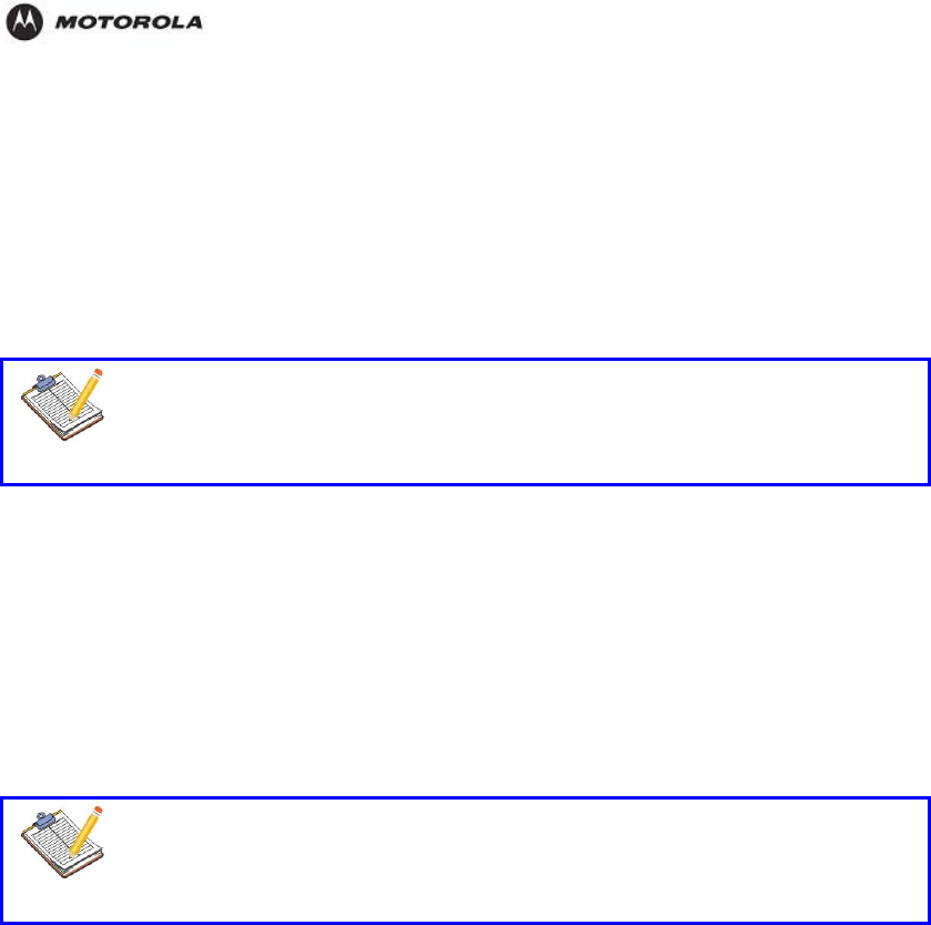
Troubleshooting
I cannot make a call via VoIP.
Your telephone is correctly connected to the HH1620.
Your telephone is working on the PSTN network:
‧Connect your phone directly to PSTN.
‧Try to make a phone call.
Your phone number, user name, and password is configured correctly.
The registrar’s and proxy server’s IP address and port number are configured correctly.
The PWR, PPP and VoIP Ready LEDs are on.
Note
As soon as the VoIP Ready LED turns on, you will hear a click, indicating the
switch from PSTN to VoIP.
I cannot make a call via PSTN (the regular phone line).
Your telephone is correctly connected to the HH1620.
Note: If the HH1620 is turned off, phone calls are always routed over PSTN.
Your telephone is working on the PSTN network:
‧Connect your phone directly to PSTN.
‧Try to make a phone call.
The Forced FXO service is activated, or whether your service provider requested you to
dial an extra prefix for making calls via PSTN.
Note
If VoIP is enabled (VoIP Ready LED is on), and when making a forced FXO call,
you will hear a click, indicating the switch from VoIP to PSTN.
How to reset my HH1620?
You might consider a reset to factory defaults as described below.
You can choose between:
Software reset
Hardware reset
A reset to factory default settings deletes the configuration profile settings.
Therefore, after the reset, a reconfiguration of your HH1620 will be needed.
Software reset Proceed as follows:
1. Go to the HH1620 Web pages.
2. In the menu, select Management > Restore Default.
3. Click Restore Default Settings. The HH1620 restarts.
4. The HH1620 returns to the HH1620 home page (unless the IP address of your computer
is not in the same subnet as the default IP address of the HH1620, being 192.168.1.1).
d
Har ware reset Proceed as follows:
1. Make sure the HH1620 is turned on.
Use a pen or an unfolded paperclip to push the recessed reset button on the back pane
The reset button is marked with a red
2. l.
circle. Push it until the power LED lights red - this
will take about 7 seconds.
HH1620 Wireless VoIP Gateway
User’s Guide 70

Troubleshooting
3. Release the reset button.
4. The HH1620 restarts.
HH1620 Wireless VoIP Gateway
User’s Guide 71
Appendix. Device Specifications
Default IP Address 192.168.1.1
Default Subnet Mask 255.255.255.0 (24 bits)
DHCP Pool 192.168.1.32 to 192.168.1.64
Default Password admin
Built-in Switch Three auto-negotiating, auto MDI/MDI-X 10/100 Mbps RJ-45
Ethernet ports
USB ports
PHONE Ports 2 RJ-11 FXS POTS ports.
RESET Button Restores factory defaults
Antenna One non-detachable external dipole antenna, 2dBi
Dimensions 248 W x 168 D x 37 H mm
Weight 350g
Power Specification 12VDC 1A
Operation Temperature 0º C ~ 40º C
Storage Temperature -20º ~ 60º C
Operation Humidity 20% ~ 95% RH
Storage Humidity 20% ~ 95% RH
HH1620 Wireless VoIP Gateway
User’s Guide 72

Glossary
This glossary defines terms and abbreviations used in this manual.
10/100Base-T See Ethernet.
Adapter A device or card that connects a computer, printer, or other peripheral
device to the network or to some other device. An Ethernet adapter
connects a computer to the LAN.
Ad-Hoc Network A temporary local area network connecting AP clients together, usually just
for the duration of the communication session. The clients communicate
directly to each other and not through an established, such as through a
router. Also known as IBSS (Independent Basic Service Set).
Broadband High-speed telecommunication over a wide range of frequencies, typically
256 Kbps or faster. Broadband enables more information to be transmitted
in less time. The most common broadband service types available to
homes and small-offices are cable modem and DSL. Both cable modem
and DSL are much faster than a traditional dial-up Internet connection.
Broadband
Provider If you have a cable modem, the cable company from which you subscribe
to high-speed data service. If you have a DSL modem, the telephone
company from which you subscribe to DSL service.
BSS Basic Service Set. A configuration of Access Points that communicate with
each other without resorting any infrastructure. Also known as Ad-Hoc
networks. Also see ESS.
Cable Modem A device enabling a broadband connection to the Internet over cable
television lines. It requires a subscription for high-speed data service from
your local cable provider.
Coaxial Cable
(Coax) A type of wire consisting of a center wire surrounded by insulation and a
grounded shield of braided wire traditionally used mainly to carry cable
television signals. The shield minimizes electrical and radio frequency
interference.
DDNS Dynamic Domain Name System enables you to assign a fixed host and
domain name to a dynamic Internet IP address. It is used when you are
hosting your own web server, FTP server, or another server behind the
router.
Default Gateway A designated router that forwards all traffic not addressed to a host on the
local subnet.
DHCP A Dynamic Host Configuration Protocol server dynamically assigns IP
addresses to client hosts on an IP network. DHCP eliminates the need to
manually assign static IP addresses by “leasing” an IP address and subnet
mask to each client. It enables the automatic reuse of unused IP
addresses. The HH1620 can simultaneously be a DHCP client and a
DHCP server:
A DHCP server at xxxx headend assigns a WAN IP address to your
HH1620.
The HH1620 contains a built-in DHCP server that assigns private IP
addresses to each computer on its LAN.
DMZ A “de-militarized zone” is one or more hosts logically located between a
private LAN and the Internet. A DMZ prevents direct access by outside
users to private data. (The term comes from the geographic buffers located
between some conflicting countries such as North and South Korea.) In a
typical small DMZ configuration, the DMZ host receives requests from
private LAN users to access external web sites and initiates sessions for
these requests. The DMZ host cannot initiate a session back to the private
LAN. Internet users outside the private LAN can access only the DMZ host.
You can use a DMZ to set up a web server or for gaming without exposing
confidential data.
DOCSIS The Data-Over-Cable Service Interface Specification define a standard
it f f bl d
t dli dt bt bl t k d
HH1620 Wireless VoIP Gateway
User’s Guide 73

interface for cable modems to deliver data between a cable network and
computer systems. Euro-DOCSIS is DOCSIS adapted for use in Europe.
DNS The Domain Name System is the Internet system for converting domain
names to IP addresses. ADNS server contains a table matching domain
names such as Internetname.com to IP addresses such as 192.169.9.1.
When you access the Web, a DNS server translates the URL displayed on
the browser to the destination website IP address. The DNS lookup table is
a distributed Internet database; no one DNS server lists all domain-to-IP
address matches.
Domain name A unique name, such as motorola.com, that maps to an IP address.
Domain names are typically much easier to remember than IP addresses.
Dotted-decimal
Format Method of representing an IP address or subnet mask using four decimal
numbers called octets. Each octet represents eight bits. In a class C IP
address, the octets are “network.network.network.host.” The first three
octets together represent the network address and the final octet is the
host address. In the HH1620 LAN default configuration, 192.168.15
represents the network address. In the final octet, the host address can be
from 2 to 254.
Download To copy a file from one computer or other network device to another. You
can use the Internet to download files from a server to your home
computer. Your voice gateway downloads its configuration file and
firmware from XXXX.
Downstream In a cable data or DSL network, the direction of data received by your
computer from the Internet.
Driver Software that enables a computer to interact with a network or other
device. For example, there are drivers for printers, monitors, graphics
adapters, modems, Ethernet, USB, and many others.
DSL A digital subscriber line enables a broadband connection to the Internet
over traditional telephone lines that support DSL. You need a subscription
for DSL service from your local telephone company.
DSSS Direct-Sequence Spread Spectrum. DSSS is a transmission technology
used in WLAN transmissions where a data signal at the sending station is
combined with a higher data rate bit sequence, or chipping code, that
divides the user data according to a spreading ratio. The chipping code is a
redundant bit pattern for each bit that is transmitted, which increases the
signal's resistance to interference. If one or more bits in the pattern are
damaged during transmission, the original data can be recovered due to
the redundancy of the transmission.
Dynamic IP
Address An IP address that is temporarily leased to a host by a DHCP server. The
opposite of static IP address.
ESS An Extended Service Set (ESS) is a set of two or more BSSs that form a
single subnetwork. See also BSS.
Ethernet The most widely used type of local area network (LAN). The most
commonly installed Ethernet networks are called 10Base-T. 10Base-T
provides transmission speeds up to 10 megabits per second (Mbps),
usually over twisted-pair wire. Fast Ethernet (100Base-T) provides
transmission speeds up to 100 Mbps.
Event A message generated by a device to inform an operator or the network
management system that something has occurred.
F-type
Connector A type of connector used to connect coaxial cable to equipment such as
the HH1620.
Firewall A security software system on the HH1620 that enforces an access control
policy between the Internet and the HH1620 LAN.
Firmware Code written onto read-only memory (ROM) or programmable read-only
memory (PROM). Once firmware has been written onto the ROM or
PROM, it is retained even when the device is turned off. Firmware is
HH1620 Wireless VoIP Gateway
User’s Guide 74

upgradeable.
Flow A data path moving in one direction.
GUI graphical user interface
Hexadecimal A base-sixteen numbering system that uses sixteen sequential numbers (0
to 9 and the letters A to F) as base units before adding a new position. On
computers, hexadecimal is a convenient way to express binary numbers.
HFC A hybrid fiber/coaxial cable network uses fiber-optic cable as the trunk and
coaxial cable to the subscriber premises.
Host Any computer or similar device supporting end-user applications or
services with full two-way network access. Each host has a unique host
number that combined with the network number forms its IP address.
Hub On a LAN, a device that connects multiple hosts to the LAN. A hub
performs no data filtering. See also router.
ICMP Internet Control Message Protocol is a protocol used for error, problem,
and informational messages sent between IP hosts and gateways. ICMP
messages are processed by the IP software and are not usually apparent
to the end-user.
IGMP Internet Group Management Protocol
Internet A worldwide collection of interconnected networks, all using TCP/IP.
IP Internet Protocol is a set of standards that enable different types of
computers to communicate with one another and exchange data through
the Internet. IP provides the appearance of a single, seamless
communication system and makes the Internet a virtual network.
IP address An Internet Protocol address identifies a computer or other device on a
TCP/IP network. Networks using the TCP/IP protocol route messages
based on the destination IP address.
IPSec The Internet Protocol Security protocols are authentication and encryption
standards for secure data exchange over the Internet.
ISP Internet service provider
LAN A local area network provides a full-time, high-bandwidth connection over a
limited area, such as a building, campus, office, or home. The computers
and other devices you connect to your voice gateway, except for the
telephones, form a LAN. Ethernet is the most widely used LAN standard.
MAC address The Media Access Control address uniquely identifies each device
that can be connected to an Ethernet network. It is permanently written to
read-only memory (ROM) at the factory and printed on your HH1620.
MHz Mega hertz. A measure of frequency; one MHz means one million cycles
per second.
Multicast A data transmission sent from one sender to multiple receivers. See also
broadcast and unicast.
NAT Network Address Translation is a standard for a LAN to use one set of IP
addresses for internal traffic and a second set of IP addresses for external
traffic.
NAPT Network Address Port Translation is the most common form of translation
between public and private IP addresses.
Network Two or more computers connected to communicate with each other.
Networks have traditionally been connected using some kind of wiring.
NIC Network interface card is another name for network adapter. A NIC is
installed in an expansion slot or can be built-in. Every Ethernet NIC has a
MAC address permanently saved in its ROM.
OOB DTMF Out-of-Band Dual-Tone Multi-Frequency protocol for voice traffic.
PING A network utility that tests host reachability by sending a small packet to
the host and waiting for a reply. If you PING a computer IP address and
receive a reply, you know the computer is reachable over the network. It
HH1620 Wireless VoIP Gateway
User’s Guide 75

also stands for “Packet InterNet Groper.”
Port On a computer or other electronic device, a port is a socket or plug used to
physically connect it to the network or to other devices. In TCP/IP, a port is
a number from 0 to 65536 used logically by a client program to specify a
server program. Ports 0 to 1024 are reserved.
Port Triggering A mechanism that enables incoming communication with specified
applications. Primarily used for gaming applications.
POTS “Plain old telephone service;” basic analog telephone service. POTS uses
the lowest 4 kHz of bandwidth on twisted pair wiring.
PPP Point-to-Point Protocol is a method to establish a network connection or
session between hosts.
PPPoE Point-to-Point Protocol over Ethernet is a specification for connecting to the
Internet used with DSL modems.
PPTP Point-to-Point Tunneling Protocol encapsulates other protocols to create
VPNs. It is developed jointly by several vendors.
Private IP
Address An IP address assigned to a computer on the HH1620 LAN by the DHCP
server on the HH1620 for a specified lease time. Private IP addresses are
used by the HH1620 LAN only; they are invisible to devices on the Internet.
See also public IP address.
PSTN The public switched telephone network is the traditional circuit-switched,
voice-oriented telephone network. See also POTS.
Public IP
Address A public IP address is visible to devices on the Internet. See also private IP
address.
QoS quality of service
RIP Routing Information Protocol enables routers to exchange routing
information with other network routers. Any RIP-enabled router:
Sends automatic update packets containing its routing table
periodically (every 30 seconds)
Accepts periodic updates from other routers and adds, deletes, or
modifies routes in its routing table accordingly
Responds to requests for its routing table
RTP Real Time Protocol for voice traffic.
RJ-11 The most common type of connector for household or office phones.
RJ-45 The most common type of port for Ethernet networks.
Roaming The ability to transfer your wireless session from one AP to another AP
seamlessly.
Router On IP networks, a device connecting at least two networks, which may or
may not be similar. A router filters data based on the IP address,
examining the source and destination IP addresses to determine the best
route on which to forward it.
Routing Table A table listing available routes that is used by a router to determine the
best route for a packet.
Server A dedicated computer that supplies files, data, or services to other “client”
computers or devices.
SIP Session Initiation Protocol for voice traffic.
S-MTA A standalone media terminal adapter converts analog voice signals to and
from a standard telephone to digital data that can be transmitted through a
broadband connection over the Internet.
SSH secure shell
Stateful
Inspection A type of firewall that tracks each connection traversing all firewall
interfaces to ensure validity. In addition to examining the source and
destination in the packet header based on static rules, a stateful inspection
firewall:
HH1620 Wireless VoIP Gateway
User’s Guide 76

Examines packet headers on context established by previous packets
that traversed the firewall
Monitors the connection state and saves it in a table
Closes ports until a connection to a specific port is requested
May examine the packet contents up through the application layer to
determine more than just the source and destination
A stateful-inspection firewall is more advanced than a static filter firewall.
Static Filter A type of firewall that examines the source and destination in the packet
header based on administrator-defined rules only.
Static IP address An IP address that is permanently assigned to a host. Normally,
a static IP address must be assigned manually. The opposite of dynamic
IP address.
Subnet Mask A bit mask that is logically ANDed with the destination IP address of a
packet to determine the network address. A router routes packets using
the network address.
Subnetwork A part of a network; commonly abbreviated “subnet.” When subnetting is
used, the host portion of the IP address is divided into a subnet and host
number. Hosts and routers use the subnet mask to identify the bits used
for the network and subnet number.
TCP Transmission Control Protocol provides reliable transport over the network
for data transmitted using IP. It defines rules and procedures for data
exchange.
TCP/IP The Transmission Control Protocol/Internet Protocol is a set of protocols
that provides rules for communication between networks. It is the
worldwide internetworking standard and the basic communications protocol
of the Internet.
TFTP Trivial File Transfer Protocol is a very simple protocol used to transfer files.
Unicast A point-to-point data transmission sent from one sender to one receiver.
This the normal way you access websites. See also multicast.
UPnP Universal Plug and Play protocol.
UPS A universal power supply provides battery back-up for a specified time
during a power outage.
Upstream In a cable data or DSL network, the direction of data sent from your
computer to the Internet.
USB Universal Serial Bus
Wireless Access
Point (WAP) A device that provides network connectivity to one or more client
computers using radio signals over a wireless connection. One example
you could use with your voice gateway is the Motorola Wireless Access
Point WA840G.
VoIP Voice over Internet Protocol is a method to exchange voice, fax, and other
information over the Internet. Voice and fax have traditionally been carried
over telephone lines using a dedicated circuit for each line. VoIP enables
calls to travel as discrete data on shared lines.
VoIP provider The company from which you purchase VoIP telephone service.
VPN
A
virtual private network is a private network that uses “virtual” connections
(tunnels) routed over a public network (usually the Internet) to provide a
secure and fast connection, usually to users working remotely at home or
in small branch offices. A VPN connection provides security and
performance similar to a dedicated link (for example, a leased line), but at
much lower cost.
WAN A wide-area network provides a connection over a large geographic area,
such as a country or the whole world. The bandwidth depends on need
and cost, but is usually much lower than for a LAN. For the voice gateway,
“WAN” refers to the VoIP and broadband provider networks.
HH1620 Wireless VoIP Gateway
User’s Guide 77

WAP Wireless Access Point or Wireless Access Protocol. See also Access
Point.
WEP Wired Equivalent Privacy encryption protects the privacy of data
transmitted over a wireless LAN. WEP uses keys to encrypt and decrypt
transmitted data. The access point must authenticate a client before it can
transfer data to another client. WEP is part of IEEE 802.11b.
Wi-Fi Wireless fidelity (pronounced why'-fy) brand name applied to products
supporting IEEE 802.11b/g.
WLAN Wireless LAN.
WME Wireless Media Extensions (WME) is another acronym commonly used for
WMM features.
WMM Wi-Fi Multimedia, which optimizes the multimedia (e.g., voice, video)
sharing over the network.
WPA Wi-Fi Protected Access. A security regimen developed by IEEE for
protection of data on a WLAN.
World Wide Web An interface to the Internet that you use to navigate and hyperlink to
information.
HH1620 Wireless VoIP Gateway
User’s Guide 78

Software License
Motorola, Inc., Connected Home Solutions (“Motorola”) 101 Tournament Drive, Horsham, PA 19044 IMPORTANT:
PLEASE READ THIS SOFTWARE LICENSE (“LICENSE”) CAREFULLY BEFORE YOU INSTALL, DOWNLOAD OR
USE ANY APPLICATION SOFTWARE, USB DRIVER SOFTWARE, FIRMWARE AND RELATED
DOCUMENTATION (“SOFTWARE”) PROVIDED WITH MOTOROLA’S VOICE GATEWAY PRODUCT (THE “VOICE
GATEWAY PRODUCT”). BY USING THE VOICE GATEWAY PRODUCT AND/OR INSTALLING, DOWNLOADING
OR USING ANY OF THE SOFTWARE, YOU INDICATE YOUR ACCEPTANCE OF EACH OF THE TERMS OF THIS
LICENSE. UPON ACCEPTANCE, THIS LICENSE WILL BE A LEGALLY BINDING AGREEMENT BETWEEN YOU
AND MOTOROLA. THE TERMS OF THIS LICENSE APPLY TO YOU AND TO ANY SUBSEQUENT USER OF THIS
SOFTWARE.
IF YOU DO NOT AGREE TO ALL OF THE TERMS OF THIS LICENSE (I) DO NOT INSTALL OR USE THE
SOFTWARE AND (II) RETURN THE VOICE GATEWAY PRODUCT AND THE SOFTWARE (COLLECTIVELY,
“PRODUCT”), INCLUDING ALL COMPONENTS, DOCUMENTATION AND ANY OTHER MATERIALS PROVIDED
WITH THE PRODUCT, TO YOUR POINT OF PURCHASE OR SERVICE PROVIDER, AS THE CASE MAY BE, FOR
A FULL REFUND.
The Software includes associated media, any printed materials, and any “online” or electronic documentation, as well
as any updates, revisions, bug fixes, or drivers obtained by you from Motorola or your service provider. Software
provided by 3rd parties may be subject to separate end-user license agreements from the manufacturers of such
Software.
The Software is never sold. Motorola licenses the Software to the original customer and to any subsequent licensee
for personal use only on the terms of this License. Motorola and its 3rd party licensors retain the ownership of the
Software.
You may:
USE the Software only in connection with the operation of the Product.
TRANSFER the Software (including all component parts and printed materials) permanently to another person, but
only if the person agrees to accept all of the terms of this License. If you transfer the Software, you must at the same
time transfer the Product and all copies of the Software (if applicable) to the same person or destroy any copies not
transferred.
TERMINATE this License by destroying the original and all copies of the Software (if applicable) in whatever form.
You may not:
(1) Loan, distribute, rent, lease, give, sublicense or otherwise transfer the Software, in whole or in part, to any other
person, except as permitted under the TRANSFER paragraph above. (2) Copy or translate the User Guide included
with the Software, other than for personal use. (3) Copy, alter, translate, decompile, disassemble or reverse engineer
the Software, including but not limited to, modifying the Software to make it operate on non-compatible hardware. (4)
Remove, alter or cause not to be displayed, any copyright notices or startup message contained in the Software
programs or documentation. (5) Export the Software or the Product components in violation of any United States
export laws.
The Product is not designed or intended for use in on-line control of aircraft, air traffic, aircraft navigation or aircraft
communications; or in design, construction, operation or maintenance of any nuclear facility. MOTOROLA AND ITS
3rd PARTY LICENSORS DISCLAIM ANY EXPRESS OR IMPLIED WARRANTY OF FITNESS FOR SUCH USES.
YOU REPRESENT AND WARRANT THAT YOU SHALL NOT USE THE PRODUCT FOR SUCH PURPOSES.
Title to this Software, including the ownership of all copyrights, mask work rights, patents, trademarks and all other
intellectual property rights subsisting in the foregoing, and all adaptations to and modifications of the foregoing shall
at all times remain with Motorola and its 3rd party licensors. Motorola retains all rights not expressly licensed under
this License. The Software, including any images, graphics, photographs, animation, video, audio, music and text
incorporated therein is owned by Motorola or its 3rd party licensors and is protected by United States copyright laws
and international treaty provisions. Except as otherwise expressly provided in this License, the copying, reproduction,
distribution or preparation of derivative works of the Software, any portion of the Product or the documentation is
strictly prohibited by such laws and treaty provisions. Nothing in this License constitutes a waiver of Motorola’s rights
under United States copyright law.
This License and your rights regarding any matter it addresses are governed by the laws of the Commonwealth of
Pennsylvania, without reference to conflict of laws principles. THIS LICENSE SHALL TERMINATE
AUTOMATICALLY if you fail to comply with the terms of this License.
Motorola is not responsible for any 3rd party software provided as a bundled application, or otherwise, with the
Software.
U.S. GOVERNMENT RESTRICTED RIGHTS
The Product and documentation is provided with RESTRICTED RIGHTS. The use, duplication or disclosure by the
Government is subject to restrictions as set forth in subdivision (c)(1)(ii) of The Rights in Technical Data and
Computer Software clause at 52.227-7013. The contractor/manufacturer is Motorola, Inc., Connected Home
Solutions, 101 Tournament Drive, Horsham, PA 19044.
HH1620 Wireless VoIP Gateway
User’s Guide 79

REMARK
IEEE 802.11b or 802.11g operation of this product in the U.S.A. is firmware-limited to channels 1 through 11.
This equipment has been tested and found to comply with the limits for a class B digital device, pursuant to part 15 of the FCC rules. These
limits are designed to provide reasonable protection against harmful interference in a residential installation. This equipment generates, uses
and can radiate radio frequency energy and, if not installed and used in accordance with the installation. , May cause harmful interference to
radio communication. However, there is no guarantee that interference
Will not occur in a particular installation. if this equipment does cause harmful interference to radio or television reception, which can be
determined by turning the equipment off and on, the user is encouraged to try to correct the interference by one or more of the following
measures:
-Reorient or relocate the receiving antenna
-Increase the separation between the equipment and receiver
-Connect the equipment into an outlet on a circuit different from that to which the receiver is connected
-Consult the dealer or an experienced radio / TV technician for help
You are cautioned that changes or modifications not expressly approved by the party responsible for compliance could void your authority to
operate the equipment.
This transmitter must not be co-located or operating in conjunction with any other antenna or transmitter.
Regulatory statement
European standards dictate maximum radiated transmit power of 100mW EIRP and frequency range 2.400-2.4835GHz; In France, the
equipment must be restricted to the 2.454 -2.4835GHz frequency range and must be restricted to indoor use.
CE Declaration of Conformity
For the following equipment: DSL VoIP Wireless Gateway
!
0984
Is herewith confirmed to comply with the requirements set out in the Council Directive on the Approximation of the Laws of the Member
States relating to Electromagnetic Compatibility (89/336/EEC), Low-voltage Directive (73/23/EEC) and the Amendment Directive
(93/68/EEC), the procedures given in European Council Directive 99/5/EC and 89/3360EEC.
The equipment was passed. The test was performed according to the following European standards:
EN 300 328-2 V.1.2.1 (2001-08)
EN 301 489-1 V.1.4.1 (2002-04) / EN 301 489-17 V.1.2.1 (2002-04)
EN 50371: 2002
EN 60950: 2000
REMARK
IEEE 802.11b or 802.11g operation of this product in the U.S.A. is firmware-limited to channels 1 through 11.
You are cautioned that changes or modifications not expressly approved by the party responsible for compliance could void your authority to
operate the equipment.
This transmitter must not be co -located or operating in conjunction with any other antenna or transmitter.