ARRIS MT76125G Wi-Fi Wireless Module User Manual System
ARRIS Group, Inc. Wi-Fi Wireless Module System
ARRIS >
User Manual (System)
3871 Lakeeld Drive
Suwanee, GA 30024
USA
www.arris.com
®
VIP4402W
Installation Guide
599747-001-a
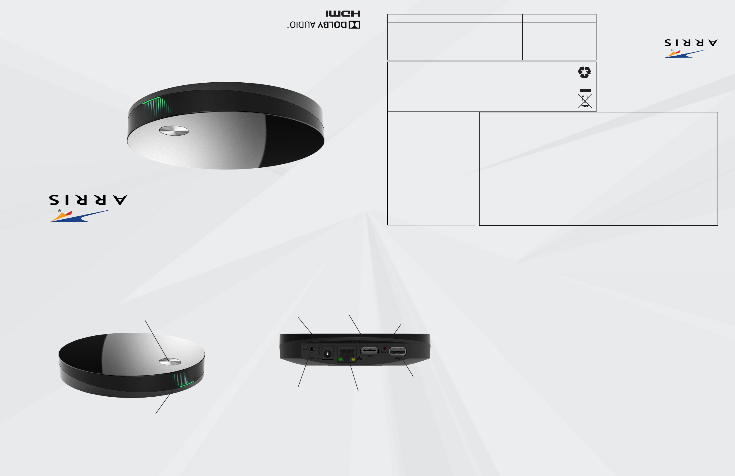
POWER
For connection to the
power supply included in
the package.
ETHERNET
For broadband connection
when no Wi-Fi network is
available.
HDMI
For connection to TV set (High
& Standard Denition digital
video and digital audio).
RESET
Press to reboot the set-top box.
STATUS INDICATOR GRID
• Solid Green: Network connection enabled (On)
• Flashing Green: Connecting to network
• Solid Amber: Network connected, strong Wi-Fi,
no video server
• Flashing Amber: Network connected, weak Wi-Fi
• Solid Red: Self diagnostic failed
• Blinking Red: Self diagnostic in progress
• No Light: No power (O)
Rear Placement
Never place the set-top box on top of or close to any heat sources such as other electronic devices. Doing so will reduce life
time and may cause irreparable damage or malfunction. Note that the ambient temperature must be below 104° F. Be sure
to maintain necessary space around the set-top box to allow for proper ventilation. Never use the set-top box outside.
The set-top box is designed to stand on a horizontal surface. It can alternatively be mounted on the wall using the ttings
on the bottom side. To mount, use M3.0 x 38 mm (#6 x 11/2 inch) screws with a at underside and maximum screw head
diameter of 6.0 mm.
This product package can include a Bluetooth® Smart remote control which makes it possible to place the set-top box in a
hidden position without line-of-sight from the remote control. There is also an IR receiver in the front panel for use with e.g.
multi-remote controls of other brands than ARRIS. When using an IR remote control line-of-sight between the front side of
the set-top box and the remote control is still required. Modern at screen TV sets and low energy lamps emit light that in
some cases may interfere with the IR signal used by remote controls.
Note that metallic surfaces and objects can interfere with the operation of Wi-Fi and/or Bluetooth® wireless technology.
If the remote control is not working properly, try altering the position of the set-top box relative to the remote control.If the
Wi-Fi connection is not working properly, try altering the position of the set-top box relative to the Wi-Fi access point.
Federal Communication Commission Interference Statement
This device complies with Part 15 of the FCC Rules. Operation is subject to the following two conditions: (1) This device may not cause harmful
interference, and (2) this device must accept any interference received, including interference that may cause undesired operation.
This equipment has been tested and found to comply with the limits for a Class B digital device, pursuant to Part 15 of the FCC Rules. These
limits are designed to provide reasonable protection against harmful interference in a residential installation. This equipment generates, uses and
can radiate radio frequency energy and, if not installed and used in accordance with the instructions, may cause harmful interference to radio
communications. However, there is no guarantee that interference will not occur in a particular installation. If this equipment does cause harm-
ful interference to radio or television reception, which can be determined by turning the equipment o and on, the user is encouraged to try to
correct the interference by one of the following measures:
-Reorient or relocate the receiving antenna.
-Increase the separation between the equipment and receiver.
-Connect the equipment into an outlet on a circuit dierent from that to which the receiver is connected.
-Consult the dealer or an experienced radio/TV technician for help.
FCC Caution: Any changes or modications not expressly approved by the party responsible for compliance could void the user’s authority to
operate this equipment.
This transmitter must not be co-located or operating in conjunction with any other antenna or transmitter.
Operations in the 5.15-5.25GHz band are restricted to indoor usage only.
Radiation Exposure Statement:
This equipment complies with FCC radiation exposure limits set forth for an uncontrolled environment. This equipment should be installed and
operated with minimum distance 20cm between the radiator & your body.
VIP4402W OVERVIEW
Front/Top
A/V (audio/video) & Mini-Toslink
For connection to TV set or audio
equipment (Standard Denition
analog video and analog audio
+ optical digital audio). Use this
connector only if your TV does
not have HDMI or if you want to
connect digital audio to a home
cinema receiver via Mini-Toslink.
Note that the analog video output
is disabled when HDMI is
connected.
STANDBY BUTTON
• Press to switch between
standby and active.
Ambient operating temperature 32-104° F at 0-95% non condensing humidity.
Voltage 100-120 V ~, 50-60 Hz
Power supply unit This Class III product, VIP4402W, shall be powered by the
Limited Power Supply that is provided together with the
product.
Maximum power consumption 7.2 W
©2016 ARRIS Enterprises, LLC. All rights reserved. No part of this publication may be reproduced in any form or by any
means or used to make any derivative work (such as translation, transformation, or adaptation) without written permission
from ARRIS Enterprises, Inc. (“ARRIS”). ARRIS reserves the right to revise this publication and to make changes in content
from time to time without obligation on the part of ARRIS to provide notication of such revision or change. ARRIS and the
ARRIS logo are all trademarks of ARRIS Enterprises, Inc. Other trademarks and trade names may be used in this document
to refer to either the entities claiming the marks and the names of their products. ARRIS disclaims proprietary interest in
the marks and names of others.
Manufactured under license from Dolby Laboratories. Dolby, Dolby Audio, Pro Logic and the double-D symbol are regis-
tered trademarks of Dolby Laboratories.
The Bluetooth® word mark and logos are registered trademarks owned by Bluetooth SIG, Inc. and any use of such marks
by ARRIS is under license.
ARRIS provides this guide without warranty of any kind, implied or expressed, including, but not limited to, the implied
warranties of merchantability and tness for a particular purpose. ARRIS may make improvements or changes in the
product(s) described in this manual at any time. The capabilities, system requirements and/or compatibility with third-party
products described herein are subject to change without notice. This installation guide is produced by the manufacturer
in the English language. Operators may elect to translate the installation guide. Any translated version of the installation
guide is created purely for the convenience of the operator and end user, and the English language version is controlling
and shall prevail. ARRIS hereby disclaims all liability for any translated versions of the installation guide created by an op-
erator, for but not limited to, the content of any translated installation guide, the accuracy of the translation and any issues
arising as a result of the translated installation guide, whether they be of an end user nature, legal nature or otherwise.
Caring for the Environment by Recycling
When you see this symbol on an ARRIS product, do not dispose of the product with
residential or commercial waste. Some countries or regions, such as the European
Union, have set up systems to collect and recycle electrical and electronic waste
items. Contact your local authorities for information about practices established for
your region.
Please recycle product packaging and this document.
Open Source Software Information
For instructions on how to obtain a copy
of any source code being made publicly
available by ARRIS related to software
used in this ARRIS product you may send
your request in writing to:
ARRIS
Software Pedigree Operations
2450 Walsh Avenue
Santa Clara, CA 95051
USA
The ARRIS website opensource.arris.com
also contains information regarding use
of open source. ARRIS has created the
opensource.arris.com site to serve as a
portal for interaction with the software
community-at-large.
USB
For connection to external devices
according to the instructions from
your service provider.
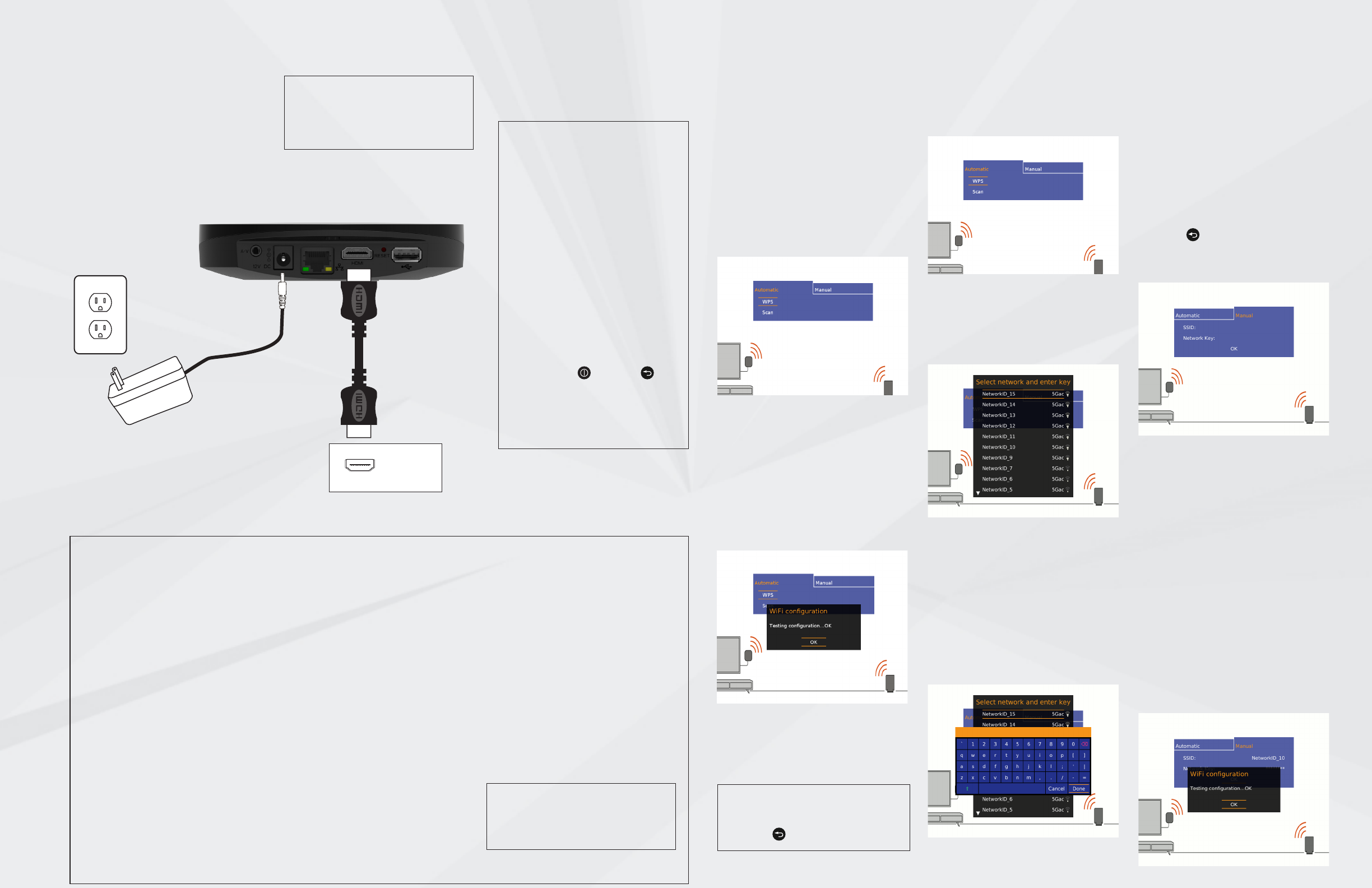
B. Scanning for Wi-Fi networks
B1. If your Wi-Fi access point does not
have a WPS button you should rst select
the “Scan” option to select your network
from a list of available networks.
B2. Select your network from the list by
moving up or down with the arrow keys
on your remote control. If your network is
not listed refer to section C. Press OK to
select your network.
B3. Press OK to launch the on-screen
keyboard. Use the arrow keys on the re-
mote control to select the correct letters
and numbers on the keyboard to enter
the Network Key (case sensitive). Press
OK to enter the selected character in the
input eld on the screen. “Backspace” is
used to erase errors. Use the arrow down
key to highlight “Done” at the bottom of
the screen when you have entered the
entire key, press OK. Highlight “Done”
again and press OK.
The conguration is tested and when the
screen shows the OK message your Wi-Fi
1 Connect to the TV set
Connect an HDMI cable between the
set-top box and the HDMI connector on
the TV set. This is the preferred method
and no other video/audio connection is
needed when HDMI is used. Note that
the analog video output is disabled when
HDMI is connected.
To display the picture from the set-top
box, the TV set must be switched to the
correct external input. This is either done
automatically or manually, using a button
on the TV remote control. See your TV
user’s guide for instructions.
2 Connect to power
Connect the power supply to the DC jack
on the set-top box and to a power outlet.
NOTE:
Do not use any power supply other
than the one supplied with the prod-
uct. Doing so may cause re or seri-
ously damage the set-top box.
4 Connect to your Wi-Fi
broadband
The recommended Wi-Fi setup method
is to use WPS. Read through all steps in
section A before you start. If your Wi-Fi
access point does not have a WPS but-
ton or WPS setup does not work, refer to
sections B or C. If the Wi-Fi network is out
of reach or unsuitable for video distribu-
tion, refer to INSTALLATION OPTIONS -
Connect to broadband via Ethernet.
A. Automatic setup using WPS
A1. When the Wi-Fi conguration setup
screen is displayed, select “WPS” using the
arrow keys on your remote control and
press OK to start the setup.
A2. You now have 2 minutes to press the
WPS button on your Wi-Fi access point.
Once you have pressed the WPS button
on your access point (within 2 minutes)
the conguration is tested and when the
screen shows the OK message your Wi-Fi
connection is established. Press OK on
your remote control to exit the setup.
If the WPS setup times out you will have
to retry until you see the OK message.
3 Prepare the remote
control
Insert the batteries in the remote control.
The remote control will initiate automatic
pairing with the set-top box when batter-
ies are inserted or on any key press.
NOTE:
You can return to the start screen by
pressing BACK ( the symbol is usually
shown as ) on your remote control.
connection is established. Press OK on
your remote control to exit the setup. If
you have entered the wrong key an error
message displays and you will have to
repeat this step.
C. Manual Wi-Fi setup
If your network is not shown in the list
you will need to manually enter both the
network name (SSID) and the key for that
network in order to connect your set-top
box.
C1. Press BACK ( the symbol is usually
shown as ) on your remote control to
return to the main screen. Select “Manual”
and press OK.
C2. Press OK to launch the on-screen
keyboard. Enter the network SSID and
Network Key using the on screen key-
board with the arrow keys on your remote
control. Please note that both the SSID
and Key are case sensitive. Press OK to
enter the selected character in the input
eld on the screen. “Backspace” is used
to erase errors. Use the arrow down key
to highlight “Done” at the bottom of the
screen when you have entered the entire
SSID and Network Key, press OK. Highlight
“Done” again and press OK.
The conguration is tested and when the
screen shows the OK message your Wi-Fi
connection is established. Press OK on
your remote control to exit the setup. If
you have entered the wrong SSID or key
an error message will show and you will
have to repeat the relevant step.
Connect video/audio with HDMI
through a home theater system or
HiFi equipment
Choose from below the option that best
ts your system conguration.
1. Digital audio equipment with HDMI
input: Connect the HDMI cable from the
set-top box to the home theater receiver,
and the home theater receiver HDMI
output to the TV set.
2. Digital audio equipment without HDMI
input: Connect the HDMI cable from the
set-top box to the TV set and an optical
Mini Toslink to Toslink cable from the set-
top box A/V output to the home theater
receiver.
Note: you may have to change your set-
tings for the TV set to ensure the digital
output is properly transmitted from the
TV set.
3. Analog audio equipment: Connect an
HDMI cable from the set-top box to the
TV set and a 3.5 mm to 3xRCA audio/
video cable in one end to the A/V connec-
tor of the set-top box and the other end
with 2xRCA to your audio equipment.
Connect video/audio to the TV set
without HDMI
If your TV does not have HDMI you can
connect a 3.5 mm to 3xRCA audio/video
cable from the A/V jack on the set-top
box to the video and R+L audio connec-
tors on the TV set. (Connectors are nor-
mally color coded: White = Left audio,
Red = Right audio, Yellow = Video.)
Connect to broadband via Ethernet
If you do not have a Wi-Fi network in your
home or if the Wi-Fi network is out of
reach or unsuitable for video distribution,
connect an Ethernet cable between the
set-top box and the router/modem or the
Ethernet wall connector as indicated by
your broadband operator. Once connect-
ed, remove and reinsert the power cable
to restart the set-top box.
INSTALLATION OPTIONS
1
2
TV
NOTE:
The set of cables and other accesso-
ries supplied by your service provider
together with this product may vary.
NOTE: Re-pairing the set-top box
with the remote control
This product package may include a
radio frequency remote control that
will be automatically paired with the
set-top box during the initial setup. If
you need to pair again, for instance
to replace the original remote control
with a new one, follow these steps:
1. Unplug the power cable.
2. Press and hold the standby but-
ton on the top cover and reinsert the
power cable.
3. Hold the standby button pressed
until the status indicator grid stops
ashing with amber light and turns
solid red.
4. Reset the remote control by press-
ing the ON/OFF and BACK keys
simultaneously for more than 3 sec-
onds. Once you have released the ON/
OFF and BACK keys press any key to
complete the pairing.