ARRIS NVG37XXR2 ARRIS FTTH User Manual ARRIS NVG37X Quick Start Guide
ARRIS Group, Inc. ARRIS FTTH ARRIS NVG37X Quick Start Guide
ARRIS >
Users Manual
Part Number: 598731-001-a
Ethernet: Use the following procedure to make an Ethernet connection on the gateway.
1. Connect the supplied RJ45 terminated Ethernet cable to one of the Ethernet ports on the back of the gateway.
2. Connect the other end of the Ethernet cable to the Ethernet port on a local computer.
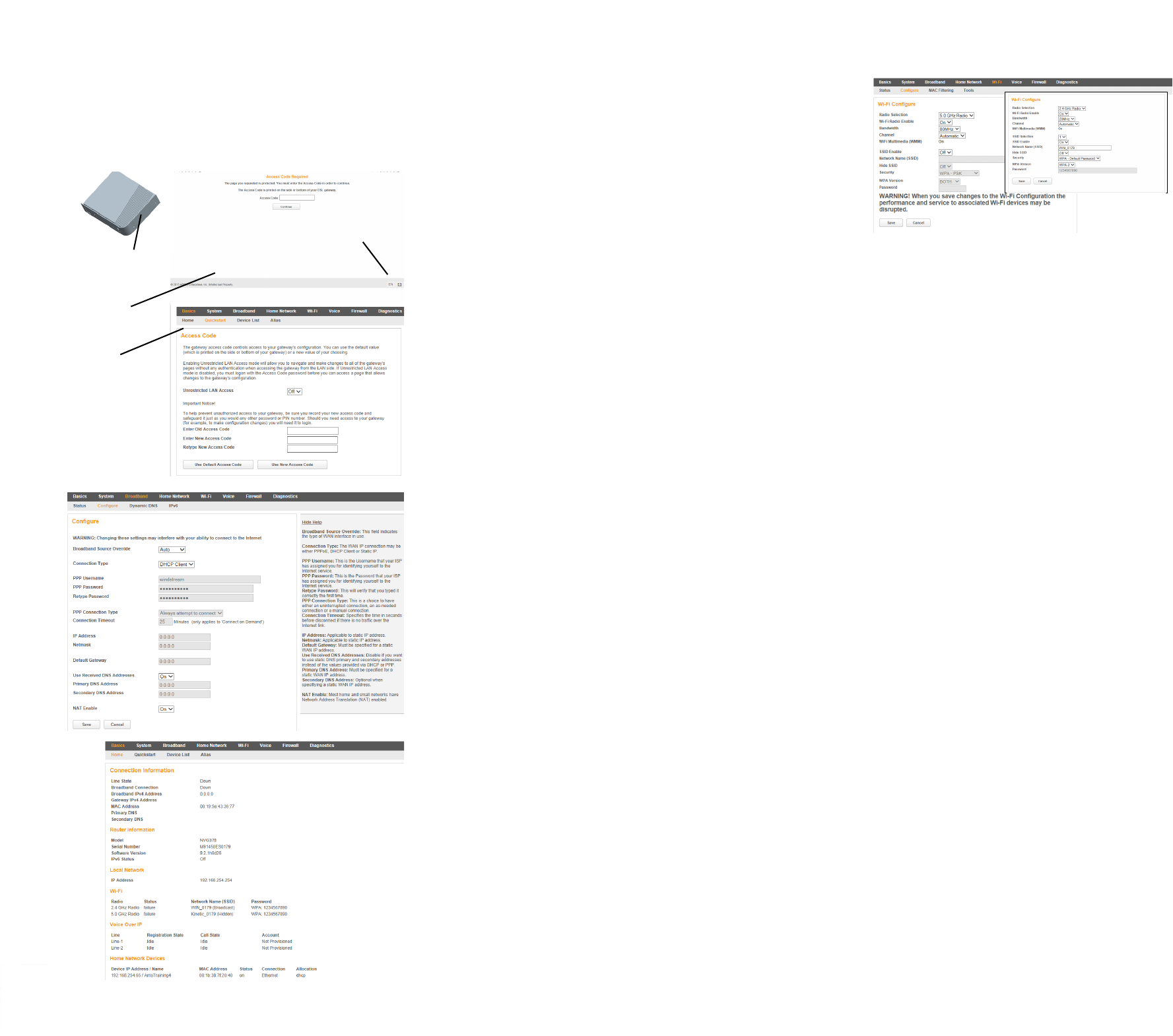
Access the Web Management Interface
1. Open a web browser, such as Firefox, Chrome, or Microsoft Internet Explorer, from the computer connected to the gateway.
2. Type the following address in the address bar of the browser to open the Access Code Required Screen:
http://192.168.1.254
Access the Web Management Configuration Pages
NOTE: When applicable, select the appropriate language button in the
lower right corner of the Access Code Required Screen to continue in the
selected language.
To access the Web Management configuration pages:
1. Provide the Device Access Code, a unique code printed on a label on
the base of the gateway.
2. Select Continue.
To continue with no changes to the code.
1. Provide the Device Access Code in the Old Access Code text box.
2. Select Use Default Access Code.
Change the Default Access Code
To change the Default Access Code, in the appropriate text boxes:
1. Enter the old access code.
2. Enter the new access code.
3. Retype the new access code.
4. Select Use New Access Code.
Quick Start User Interface
The NVG37X gateway has a Quick Start Broadband Configuration screen for
initial configuration. Use the Quick Start Broadband Configuration screen to
configure the gateway to use DHCP Client or PPPoE for the broadband IP
interface:
• If the proper connection type is not determined, use the DHCP option
from the pulldown menu and select Finish.
• If it is known that PPPoE is required, then select it and enter the user
name and password, then select Finish. When the connection is
successful, the Home Screen opens.
• If there is a failure in the connection, the notice “WAN connection was
not successful - Please reenter your broadband configuration”
appears on the Broadband Configuration screen.
Home Screen
The Home screen provides an overview of the connection and home network status.
From this screen, other detailed status and configuration screens can be accessed
including the following:
• System status/configuration, including the Restart and Reset (Factory Reset)
options
• Broadband status/configuration, including Point-to-Point (PPP) configuration
• Home network status/configuration
• Wi-Fi network status/configuration, including security settings
• Voice status/configuration
• Firewall status/configuration
•Diagnostics
Add a Wireless Device to the Gateway
1. On the wireless device, use the Wireless setup option to find the available
wireless network names. The Wi-Fi Network Name for the gateway is printed on
the bottom label along with the Wi-Fi Password.
2. On the Wi-Fi configure screen, select the network name for the gateway and
enter the password.
NOTE: Optionally, WiFi Protected Setup (WPS) can be enabled to allow wireless
devices with WPS support to join by pressing the WPS button on the front panel and
following the wireless device instructions provided. The WiFi Configure screen
provides access to enable or disable the WPS.
Declaration of Conformance
WARNING: This is a Class B product. In a domestic environment this product may cause radio interference, in which case the user may be required to take adequate
measures. Adequate measures include increasing the physical distance between this product and other electrical devices. Changes or modifications to this unit not
expressly approved by the party responsible for compliance could void the user’s authority to operate the equipment.
United States: This device complies with Part 15 of the FCC Rules. Operation is subject to the following two conditions:
1. This device may not cause harmful interference, and
2. This device must accept any interference received, including interference that may cause undesired operation.
This equipment has been tested and found to comply with the limits for a Class B digital device, pursuant to Part 15 of the FCC Rules. These limits are designed to provide
reasonable protection against harmful interference in a residential installation. This equipment generates, uses, and can radiate radio frequency energy and, if not
installed and used in accordance with the instructions, may cause harmful interference to radio communications. However, there is no guarantee that interference will
not occur in a particular installation. If this equipment does cause harmful interference to radio or television reception, which can be determined by turning the
equipment off and on, the user is encouraged to try to correct the interference by one or more of the following measures:
• Reorient or relocate the device.
• Increase the distance between the equipment being interfered with and the device.
• Connect the device to an outlet on a circuit different from the outlet to which the equipment being interfered with is connected.
• Consult the retailer or an experienced radio/TV technician for help.
United States: This device complies with 47 CFR Part 68 of the FCC Rules. Operation is subject to the following four conditions:
1. The Federal Communications Commission (FCC) has established Rules which permit this device to be directly connected to the telephone network. Standardized
jacks are used for these connections. This equipment should not be used on party lines or coin phones.
2. If this device is malfunctioning, it may also be causing harm to the telephone network; this device should be disconnected until the source of the problem can be
determined and until repair has been made. If this is not done, the telephone company may temporarily disconnect service.
3. The telephone company may make changes in its technical operations and procedures; if such changes affect the compatibility or use of this device, the telephone
company is required to give adequate notice of the changes. You will be advised of your right to file a complaint with the FCC.
4. If the telephone company requests information on what equipment is connected to their lines, inform them of:
• The telephone number to which this unit is connected.
• The ringer equivalence number. [0.XB] (Indicated on the label)
• The USOC jack required. [RJ11C]
• The FCC Registration Number. [XXXUSA-XXXXX-XX-E] (Indicated on the label)
The Ringer Equivalence Number (REN) is used to determine how many devices can be connected to your telephone line. In most areas, the sum of the REN's of all
devices on any one line should not exceed five (5.0). If too many devices are attached, they may not ring properly.
FCC Caution: Any changes or modifications not expressly approved by the party responsible for compliance could void the user’s authority to operate this equipment.
This transmitter must not be co-located or operating in conjunction with any other antenna or transmitter. Operations within the 5.15 ~ 5.25 GHz band are restricted to
indoor use only.
Radiation Exposure Statement: This equipment complies with FCC radiation exposure limits as set forth for an uncontrolled environment. This equipment should be
installed and operated maintaining a minimum distance of 24 cm between the device and your body.
Service Requirements: In the event of equipment malfunction, if under warranty, we will exchange a product deemed defective. Under FCC rules, no customer is
authorized to repair this equipment. This restriction applies regardless of whether the equipment is in or out of warranty.
Technical Support for Hardware Products:
Customers inside North America: 888-944-4357 (888-944-HELP)
Customers outside North America: 1-215-323-2345
For Spanish language support: 1-215-323-2346
IMPORTANT: This product was tested for FCC compliance under conditions that included the use of shielded cables and connectors between system components.
Changes or modifications to this product not authorized by the manufacturer could void your authority to operate the equipment.
Canada: This Class B digital apparatus meets all requirements of the Canadian Interference-Causing Equipment Regulations.
Cet appareil numérique de la classe B respecte toutes les exigences du Réglement sur le matériel brouilleur du Canada.
This device complies with RSS-210 of the Industry Canada Rules. Operation is subject to the following two conditions: (1) This device may not cause harmful interference,
and (2) this device must accept any interference received, including interference that may cause undesired operation.
Ce dispositif est conforme à la norme CNR-210 d'Industrie Canada applicable aux appareils radio exempts de licence. Son fonctionnement est sujet aux deux conditions
suivantes: (1) le dispositif ne doit pas produire de brouillage préjudiciable, et (2) ce dispositif doit accepter tout brouillage reçu, y compris un brouillage susceptible de
provoquer un fonctionnement indésirable.
Caution: (i) the device for operation in the band 5150-5250 MHz is only for indoor use to reduce the potential for harmful interference to co-channel mobile satellite
systems; (ii) the maximum antenna gain permitted for devices in the bands 5250-5350 MHz and 5470-5725 MHz shall comply with the e.i.r.p. limit; and (iii) the maximum
antenna gain permitted for devices in the band 5725-5825 MHz shall comply with the e.i.r.p. limits specified for point-to-point and non point-to-point operation as
Access Code
Device Access
Code Location
Device Access Code
Change Screen
Required Screen
Language
Selection
Buttons
Broadband Configuration Screen
Home Screen
Wi-Fi Configure Screen
Part Number: 598731-001-a
appropriate. (iv) Users should also be advised that high-power radars are allocated as primary users (i.e. priority users) of the bands 5250-5350 MHz and 5650-5850 MHz
and that these radars could cause interference and/or damage to LE-LAN devices.
Avertissement:. Le guide d’utilisation des dispositifs pour réseaux locaux doit inclure des instructions précises sur les restrictions susmentionnées, notamment :
(i) les dispositifs fonctionnant dans la bande 5 150-5 250 MHz sont réservés uniquement pour une utilisation à l’intérieur afin de réduire les risques de brouillage
préjudiciable aux systèmes de satellites mobiles utilisant les mêmes canaux;
(ii) le gain maximal d’antenne permis pour les dispositifs utilisant les bandes 5 250-5 350 MHz et 5 470-5 725 MHz doit se conformer à la limite de p.i.r.e.;
(iii) le gain maximal d’antenne permis (pour les dispositifs utilisant la bande 5 725-5 825 MHz) doit se conformer à la limite de p.i.r.e. spécifiée pour l’exploitation point à
point et non point à point, selon le cas.
(iv) De plus, les utilisateurs devraient aussi être avisés que les utilisateurs de radars de haute puissance sont désignés utilisateurs principaux (c.-à-d., qu’ils ont la priorité)
pour les bandes 5 250-5 350 MHz et 5 650-5 850 MHz et que ces radars pourraient causer du brouillage et/ou des dommages aux dispositifs LAN-EL.
Déclaration d'exposition aux radiations: Cet équipement est conforme aux limites d'exposition aux rayonnements IC établies pour un environnement non contrôlé.
Cet équipement doit être installé et utilisé avec un minimum de 24 cm de distance entre la source de rayonnement et votre corps.
European Union: This product complies with the provisions of the Low Voltage Directive 73/23/EEC and the EMC Directive 2004/108/EC. Compliance is dependent upon
the equipment being properly installed and maintained, and when it is used for the purposes for which it was intended.
Restrictions on connecting equipment: This equipment meets the applicable Industry Canada Terminal Equipment Technical Specifications. This is confirmed by the
registration number. The abbreviation, IC, before the registration number signifies that registration was performed based on a Declaration of Conformity indicating that
Industry Canada technical specifications were met. It does not imply that Industry Canada approved the equipment.
The Ringer Equivalence Number (REN) for this terminal equipment is: 0.1B for FCC and 0.0 for IC. The REN assigned to each terminal equipment provides
an indication of the maximum number of terminals allowed to be connected to a telephone interface. The termination on an interface may consist of any combination of
devices subject only to the requirement that the sum of the Ringer Equivalence Numbers of all the devices does not exceed five.
Restrictions concernant le raccordement de matériel: Le présent matériel est conforme aux spécifications techniques d’Industrie Canada applicables au matériel
terminal. Cette conformité est confirmée par le numéro d'enregistrement. Le sigle IC, placé devant le numéro d'enregistrement, signifie que l’enregistrement s’est
effectué conformément à une déclaration de conformité et indique que les spécifications techniques d'Industrie Canada ont été respectées. Il n’implique pas qu’Industrie
Canada a approuvé le matériel.
L'indice d'équivalence de la sonnerie (IES) du présent matériel est: 0.1B for FCC and 0.0 for IC. L'IES assigné à chaque dispositif terminal indique le nombre
maximal de terminaux qui peuvent être raccordés à une interface téléphonique. La terminaison d'une interface peut consister en une combinaison quelconque de
dispositifs, à la seule condition que la somme d'indices d'équivalence de la sonnerie de tous les dispositifs n'excède pas 5.
Copyright
©ARRIS Enterprises, Inc. 2015 All rights reserved. No part of this publication may be reproduced in any form or by any means or used to make any derivative work (such
as translation, transformation, or adaptation) without written permission from ARRIS Enterprises, Inc. (“ARRIS”). ARRIS reserves the right to revise this publication and to
make changes in content from time to time without obligation on the part of ARRIS to provide notification of such revision or change.
ARRIS and the ARRIS logo are all trademarks of ARRIS Enterprises, Inc. Other trademarks and trade names may be used in this document to refer to either the entities
claiming the marks and the names of their products. ARRIS disclaims proprietary interest in the marks and names of others.
ARRIS provides this guide without warranty of any kind, implied or expressed, including, but not limited to, the implied warranties of merchantability and fitness for a
particular purpose. ARRIS may make improvements or changes in the product(s) described in this manual at any time.
The capabilities, system requirements and/or compatibility with third-party products described herein are subject to change without notice.
EXCEPT AS INDICATED IN THE APPLICABLE SYSTEM PURCHASE AGREEMENT, THE SYSTEM, DOCUMENTATION AND SERVICES ARE PROVIDED “AS IS”, AS AVAILABLE,
WITHOUT WARRANTY OF ANY KIND. ARRIS GROUP, INC. (“ARRIS”) DOES NOT WARRANT THAT THE SYSTEM WILL MEET CUSTOMER'S REQUIREMENTS, OR THAT THEIR
OPERATION WILL BE UNINTERRUPTED OR ERROR-FREE, OR THAT ANY ERRORS CAN OR WILL BE FIXED. ARRIS HEREBY DISCLAIMS ALL OTHER WARRANTIES, EXPRESS OR
IMPLIED, ORAL OR WRITTEN, WITH RESPECT TO THE SYSTEM AND SERVICES INCLUDING, WITHOUT LIMITATION, ALL IMPLIED WARRANTIES OF TITLE, NON-
INFRINGEMENT, INTEGRATION, MERCHANTABILITY OR FITNESS FOR ANY PARTICULAR PURPOSE AND ALL WARRANTIES ARISING FROM ANY COURSE OF DEALING OR
PERFORMANCE OR USAGE OF TRADE.
EXCEPT AS INDICATED IN THE APPLICABLE SYSTEM PURCHASE AGREEMENT, ARRIS SHALL NOT BE LIABLE CONCERNING THE SYSTEM OR SUBJECT MATTER OF THIS
DOCUMENTATION, REGARDLESS OF THE FORM OF ANY CLAIM OR ACTION (WHETHER IN CONTRACT, NEGLIGENCE, STRICT LIABILITY OR OTHERWISE), FOR ANY (A)
MATTER BEYOND ITS REASONABLE CONTROL, (B) LOSS OR INACCURACY OF DATA, LOSS OR INTERRUPTION OF USE, OR COST OF PROCURING SUBSTITUTE TECHNOLOGY,
GOODS OR SERVICES, (C) INDIRECT, PUNITIVE, INCIDENTAL, RELIANCE, SPECIAL, EXEMPLARY OR CONSEQUENTIAL DAMAGES INCLUDING, BUT NOT LIMITED TO, LOSS OF
BUSINESS, REVENUES, PROFITS OR GOODWILL, OR (D) DIRECT DAMAGES, IN THE AGGREGATE, IN EXCESS OF THE FEES PAID TO IT HEREUNDER FOR THE SYSTEM OR
SERVICE GIVING RISE TO SUCH DAMAGES DURING THE 12-MONTH PERIOD PRIOR TO THE DATE THE CAUSE OF ACTION AROSE, EVEN IF COMPANY HAS BEEN ADVISED OF
THE POSSIBILITY OF SUCH DAMAGES. THESE LIMITATIONS ARE INDEPENDENT FROM ALL OTHER PROVISIONS OF THIS AGREEMENT AND SHALL APPLY NOTWITHSTANDING
THE FAILURE OF ANY REMEDY PROVIDED HEREIN.
All ARRIS products are furnished under a license agreement included with the product. If you are unable to locate a copy of the license agreement, please contact ARRIS.
NVG37X Ethernet and FTTH Gateway Quick Start Guide
Introduction
Use this Quick Start Guide to install, configure, and perform basic troubleshooting for the ARRIS™ NVG37X Ethernet and FTTH Gateway.
Power Supply Installation
Connect the power supply cord to the power jack on the gateway. Plug the power supply into an appropriate electrical outlet.
WARNING: The power supply must be connected to an outlet with a protective earth connection. Do not defeat the protective earth connection.
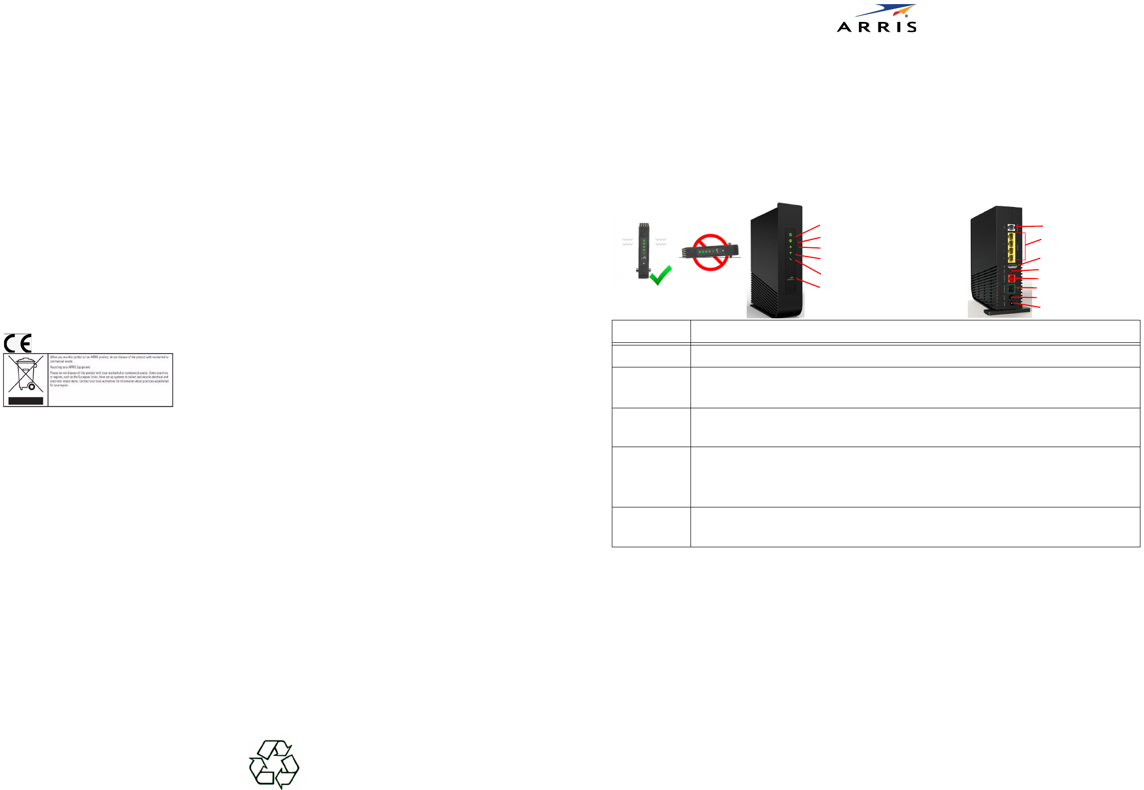
Product Ventilation
The gateway is intended for residential use. Position the gateway in an upright vertical position and locate it where temperatures remain within a range
of 32° – 104°F (0° – 40°C) and where heat from the unit itself is not trapped. There must be at least two inches (2”) of clearance on all sides except the
bottom.
Gateway Positioning, Status Indicator Lights and Port Configuration
Proper positioning of the gateway is essential for proper cooling. Colored LEDs on the gateway indicate the status of various port activity.
Powering and LED Status
Press the power button on the back of the gateway. The Power indicator will light GREEN to indicate that the gateway is powered correctly. Under
normal operation, while the gateway is powering up, LED status is as follows:
• Broadband, Ethernet, Wi-Fi, and Phone indicators will be off.
• Ethernet and Wi-Fi indicators will light GREEN to indicate that Ethernet and wireless devices are connected.
• Broadband indicator will initially light AMBER, and upon service connectivity, it will light GREEN.
• Phone indicator will light GREEN after the Broadband indicator lights GREEN to indicate that digital phone service is active.
NOTE: On initial setup, it may take several minutes to achieve service connectivity.
ONT Broadband: Use the following procedure to connect the gateway to Optical Network Termination (ONT) Ethernet.
1. Connect the supplied Ethernet cable to the ONT Broadband port on the back of the gateway.
2. Connect the other end of the Ethernet cable to the ONT connection.
SFP Broadband: This connection is NOT USER SERVICABLE and should be installed and configured by a technician only.
Phone Line: Use the following procedure to connect a phone to the gateway.
1. Connect the supplied RJ11 terminated phone cable to the Phone port on the back of the gateway.
2. Connect the phone cable to a phone or fax machine.
NOTE: Use an RJ-14 to RJ-11 splitter to connect two phone lines.
LED Status
Power Solid Green = The device is powered.
Broadband
Solid Green = Broadband Internet connection is active.
Solid Amber = Broadband is detecting, connecting, and configuring.
Solid Red = No broadband signal on the line.
LAN Ethernet
Solid Green = Any of the 4 Ethernet ports is active.
Solid Red = Failure on the Ethernet interface.
Off = No active links.
Wi-Fi
Solid Green = Wireless device or devices are connected.
Flashing Amber = Wi-Fi Protected Setup (WPS) is active.
Flashing Red = Wi-Fi Protected Setup (WPS) time-out or conflict.
Solid Red = Wireless network failure.
Off = Wireless disabled or no devices connected.
Phone
Solid Green = A VoIP voice line is registered and active.
Solid Red = No active VoIP voice line (configured but not SIP registered).
Off = VoIP is not enabled or configured.
Do Not Position
Horizontally
5cm/2”
Minimum Spacing
5cm/2”
Power
LAN Ethernet
Wi-Fi
Broadband
Phone (optional)
(Wi-Fi Protected Setup button)
WPS
Power Connection
Power Button
ONT Broadband Port
LAN Ethernet Ports
USB Port
Phone Jack (Optional)
Reset Switch
SFP Broadband Port