ARRIS OG1600CT Outdoor Access Point User Manual manual
ARRIS Group, Inc. Outdoor Access Point manual
ARRIS >
manual

Release 16 STANDARD 1.0 August 2016 © 2016 ARRIS Enterprises LLC. All Rights Reserved. 1
Safety and Compliance
FCC Compliance
This equipment has been tested and found to comply with the limits for a Class B digital device, pursuant to Part 15 of
the FCC Rules. These limits are designed to provide reasonable protection against harmful interference when the
equipment is operated in a commercial environment. This equipment generates, uses, and can radiate radio frequency
energy and, if not installed and used in accordance with the Installation Manual, may cause harmful interference to
radio communications. Operation of this equipment in a residential area is likely to cause harmful interference in which
case the user will be required to correct the interference at his/her own expense.
CAUTION: Any changes or modifications not expressly approved by ARRIS could void the user’s authority to operate this
equipment under the rules and regulations of the FCC.
Canadian Compliance
This Class A digital device complies with Canadian ICES-003.
Cet appareil numérique de la classe A est conforme à la norme NMB-003 du Canada.
Housing Instructions
This document contains information about installing the OG1600.
Preparing for Installation (page 1)
Mounting the Housing (page 2)
Connecting the Plant Cable Assembly (page 3)
OG1600 LEDs (page 4)
CAUTION ARRIS Outdoor Gateways are designed for an operating environment of -10°C to +55°C. The Mil Spec Hdbk 217
states that a 9°C increase in device operating environments will reduce the product’s reliability (and projected lifetime)
by 50%. Therefore, you should take proper care to maximize airflow around the Outdoor Gateway and to minimize
ambient temperatures.
Preparing for Installation
To prepare the OG1600 housing for installation
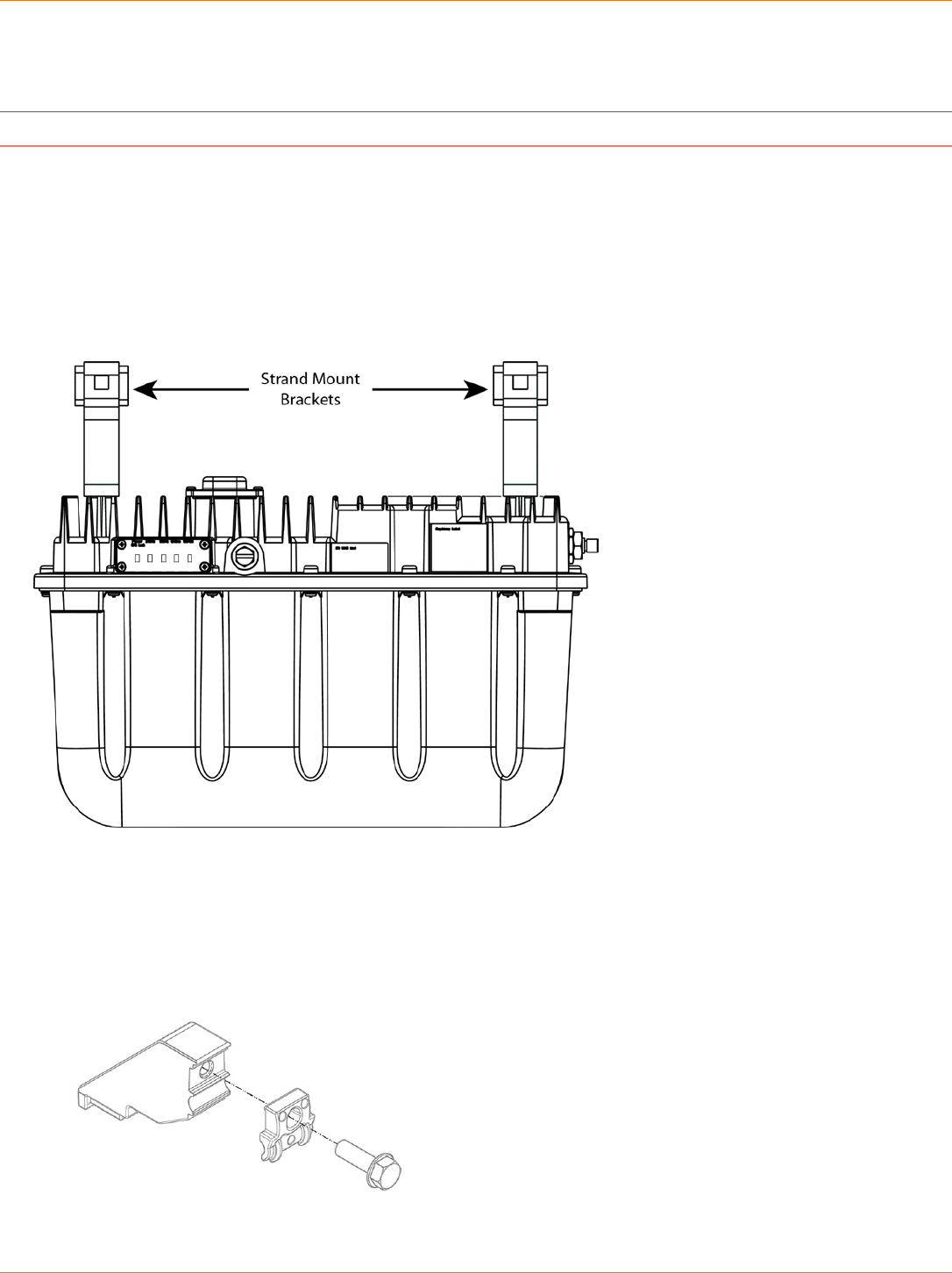
The OG1600 Outdoor Gateway is delivered without the strand mount assembly attached to the housing base.
1. Inspect the shipping carton and ensure that the strand mount assembly is present.
a. The strand mount assembly is available from ARRIS and consists of:
Two offset brackets
Two strand clamps
Two 1/4” x 1.25” length bolts
Contact ARRIS if you need to order a strand mount assembly.
2. Inspect the outside of the housing. Check the convection fins,coaxial cable entry ports, captive lid bolts, and all
service entry points for damage.
Touchstone® OG1600 Outdoor Gateway
Installation Guide
Installation Guide Touchstone® OG1600 Outdoor Gateway
Release 16 STANDARD 1.0 August 2016 © 2016 ARRIS Enterprises LLC. All Rights Reserved. 2
Mounting the Housing
IMPORTANT: The OG1600 Outdoor Gateway is not field-serviceable.
The following sections describe how to mount the OG1600.
Strand Mounting
Before you strand mount the housing, follow the instructions below to attach the strand mount brackets to the base.
1. Attach each strand mount assembly to the housing base, using the 1/4" x 0.625" length bolts that are already
installed in the top of the OG1600 chassis.
The following figure shows the strand mount brackets attached to the OG1600 housing.
Figure 1: Location of strand mount brackets attached to the OG1600 housing
2. Torque each bolt to between 4 and 6 ft-lbs (between 5.4 and 8.1 N•m)
3. Loosely attach the strand clamps to the strand mount assemblies using the 1/4” x 1.25” length bolts included with
the strand mount assembly, as shown in the following figure.
Figure 2: Attaching strand clamps to strand mount brackets

Installation Guide Touchstone® OG1600 Outdoor Gateway
Release 16 STANDARD 1.0 August 2016 © 2016 ARRIS Enterprises LLC. All Rights Reserved. 3
To strand mount the housing:
1. Lift the Outdoor Gateway so that the clamps are level with the strand, and slide the Outdoor Gateway back until the
strand engages the strand clamps.
2. Do not tighten the hex head bolts at this time. Keeping the bolts loose enables the clamps to slide along the strand
wire until the housing finally is positioned with respect to the cables.
3. Verify that the Outdoor Gateway is within 5 degrees of hanging vertically.
4. When the housing is in the required position, torque the two strand clamp bolts to between 4 and 6 ft-lbs (between
5.4 and 8.1 N•m).
Grounding the Housing
The aerial metal strand connections will serve as connection to ground.
Connecting the Plant Cable Assembly
The OG1600 includes an F-type connector which can be used to add the plant cable assembly. You will need to remove
the plastic cap covering this connector before you can connect to the plant cable assembly.
Important: The OG1600 is designed to be mounted near the cable plant tap in order to minimize the length of coaxial
cable needed to connect. Extended lengths of coaxial cable can reduce the DOCSIS receive sensitivity of the Outdoor
Gateway.
Installation Guide Touchstone® OG1600 Outdoor Gateway
Release 16 STANDARD 1.0 August 2016 © 2016 ARRIS Enterprises LLC. All Rights Reserved. 4
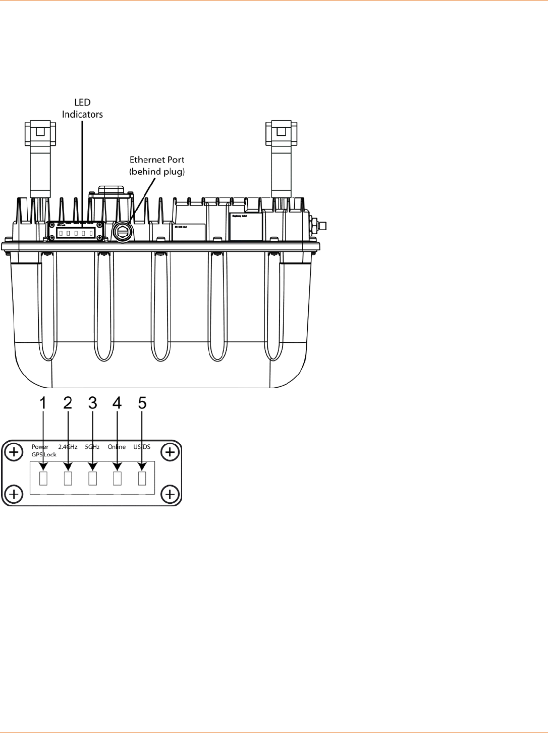
OG1600 LEDs
The OG1600 Outdoor Gateway includes several LED indicator lights on the outside of the case to assist in
troubleshooting.
1. Power: blinks to indicate that AC power is available to the unit. A solid (non-blinking) LED indicates that GPS lock has
been acquired.
2. 2.4GHz: indicates the status of the 2.4 GHz wireless LAN.
3. 5GHz: indicates the status of the 5 GHz wireless LAN.
4. Online: indicates internet data transmission status.
5. US/DS: indicates upstream/downstream connectivity.

Installation Guide Touchstone® OG1600 Outdoor Gateway
Release 16 STANDARD 1.0 August 2016 © 2016 ARRIS Enterprises LLC. All Rights Reserved. 5
LED Behavior: Normal Operation
Mode Power LED 2.4G LED 5G LED Online US/DS
AC Power On = Unit is up
and running
Flash = GPS scan
in progress
On = 2.4G Wifi Enabled
Flash = Client activity
Off = 2.4G Wifi Disabled
On = 5G Wifi Enabled
Flash = Client activity
Off = 5G Wifi Disabled
On = Internet
available
On = Connected to
Internet
No AC
Power
Off Off Off Off Off
Firmware
upgrade
Normal
Operation
Normal Operation Normal Operation Normal
Operation
Flash = Firmware
Download in
Progress
LED Behavior: Startup Sequence
Power / GPS Lock US/DS Online
On = OG1600 has power Slow Flash (1 / Second) = Downstream
acquisition in progress
Off
Flash = GPS scan in progress On (Until Upstream Acquisition Starts) Off
On = OG1600 is up and GPS scan
is done
Fast Flash (3 / Second) = Upstream
acquisition in progress
Off
On (Upstream acquisition complete) Slow Flash (during
initialization / IP acquisition)
On (when modem obtain IP address)