ARRIS SBG901 Wireless Cable Modem Gateway User Manual Motorola SURFboard
ARRIS Group, Inc. Wireless Cable Modem Gateway Motorola SURFboard
UserManual.wiki
>
ARRIS
>
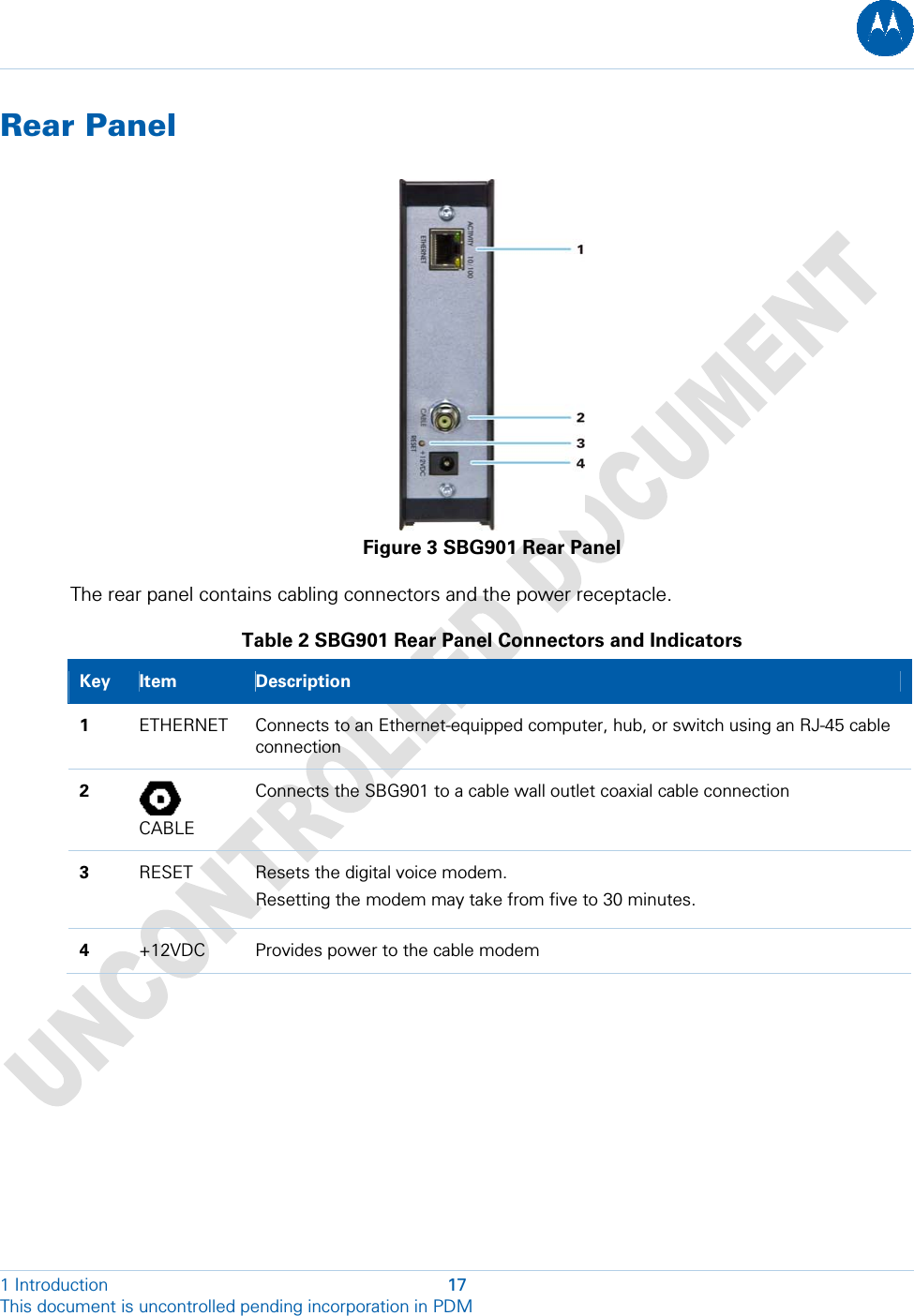
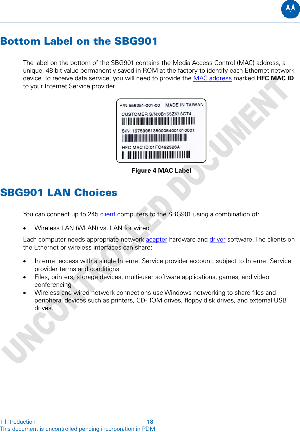
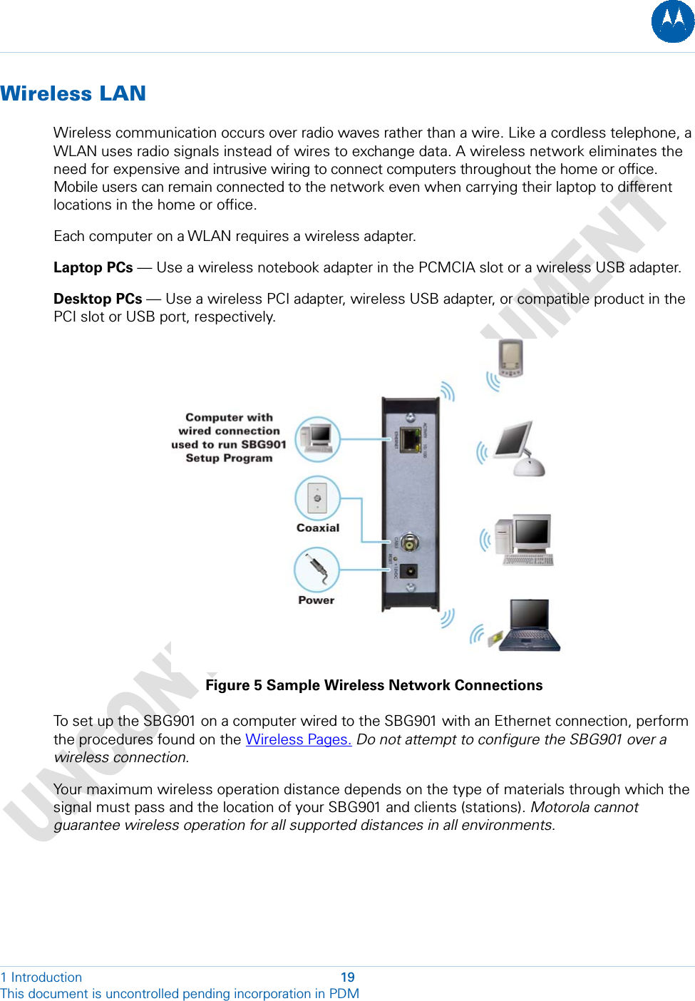
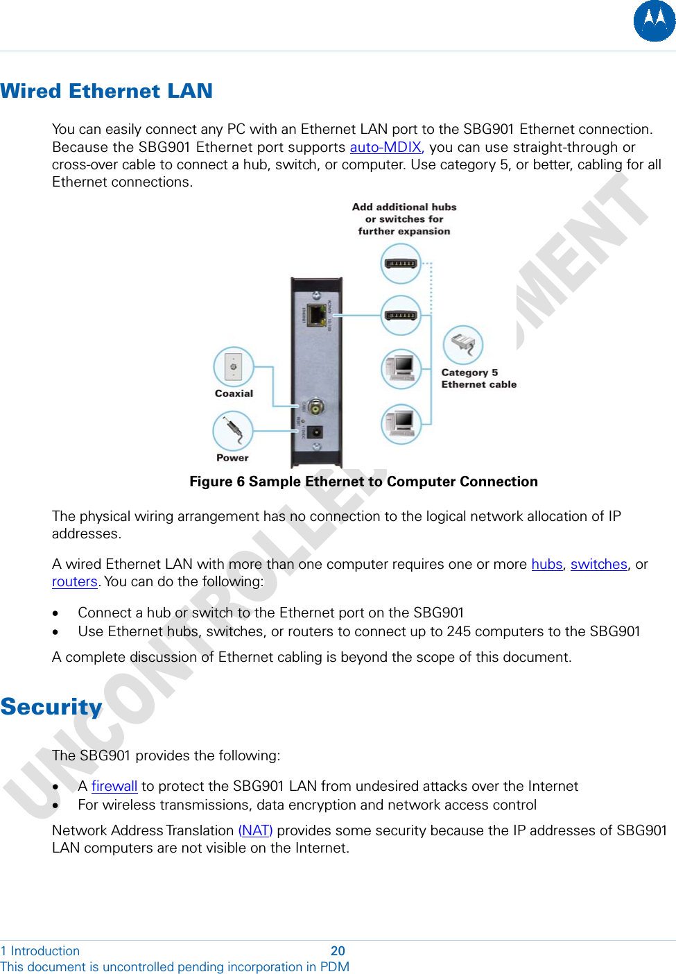
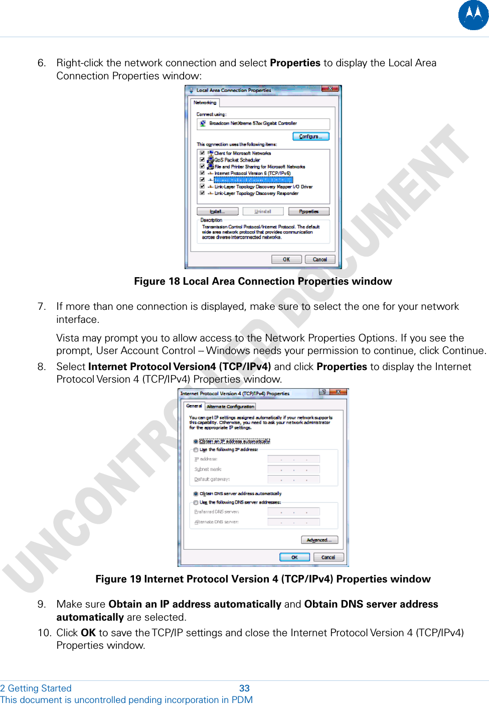
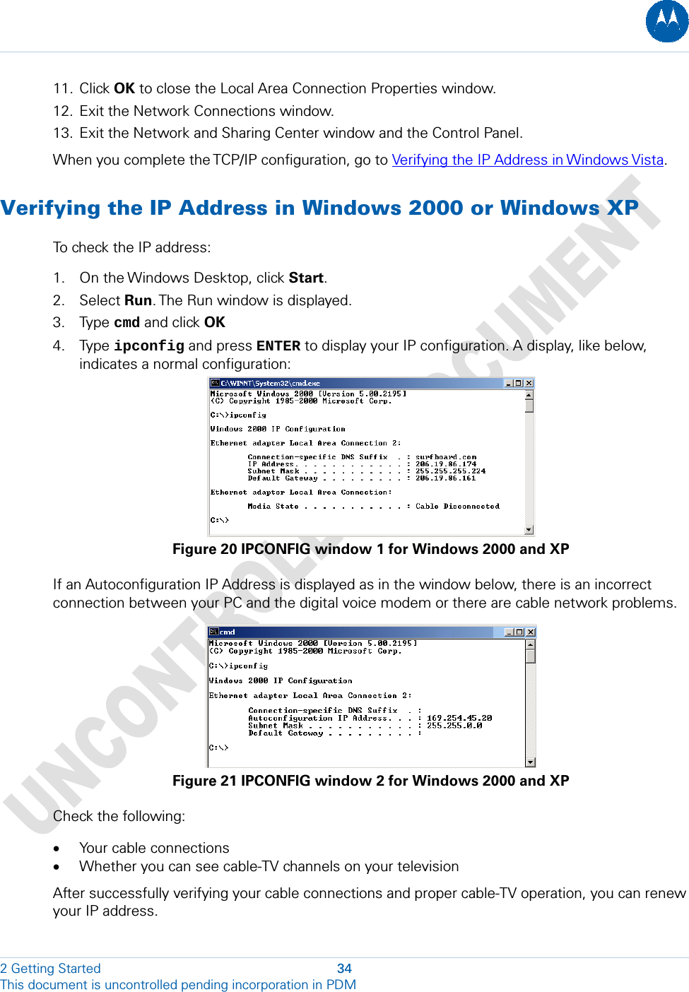
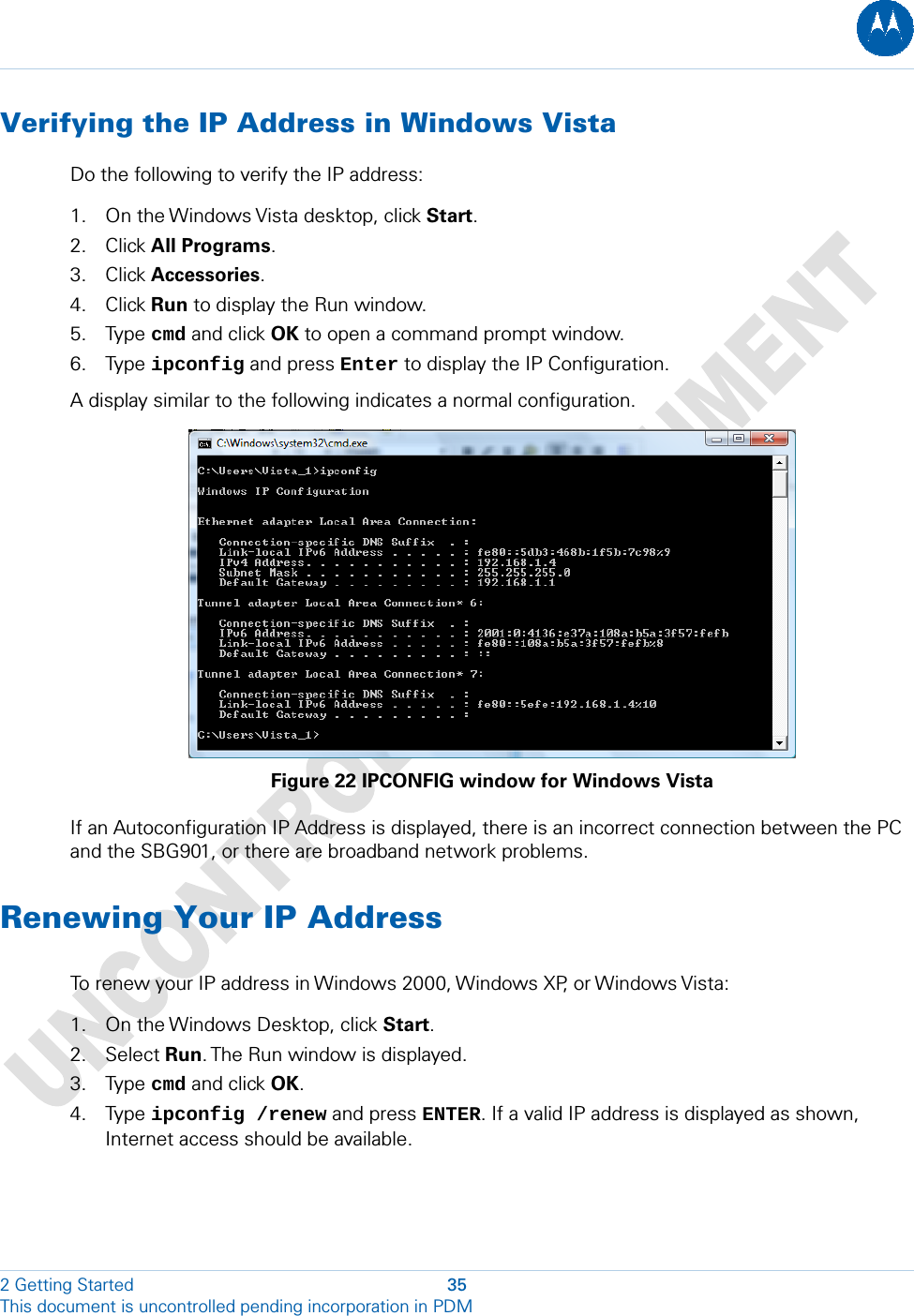
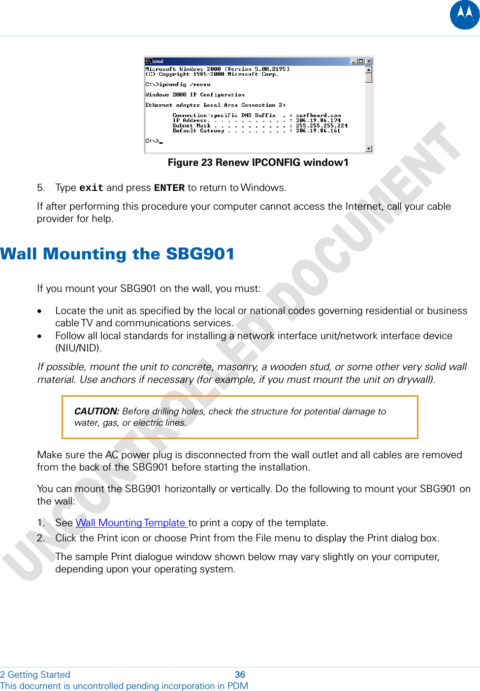
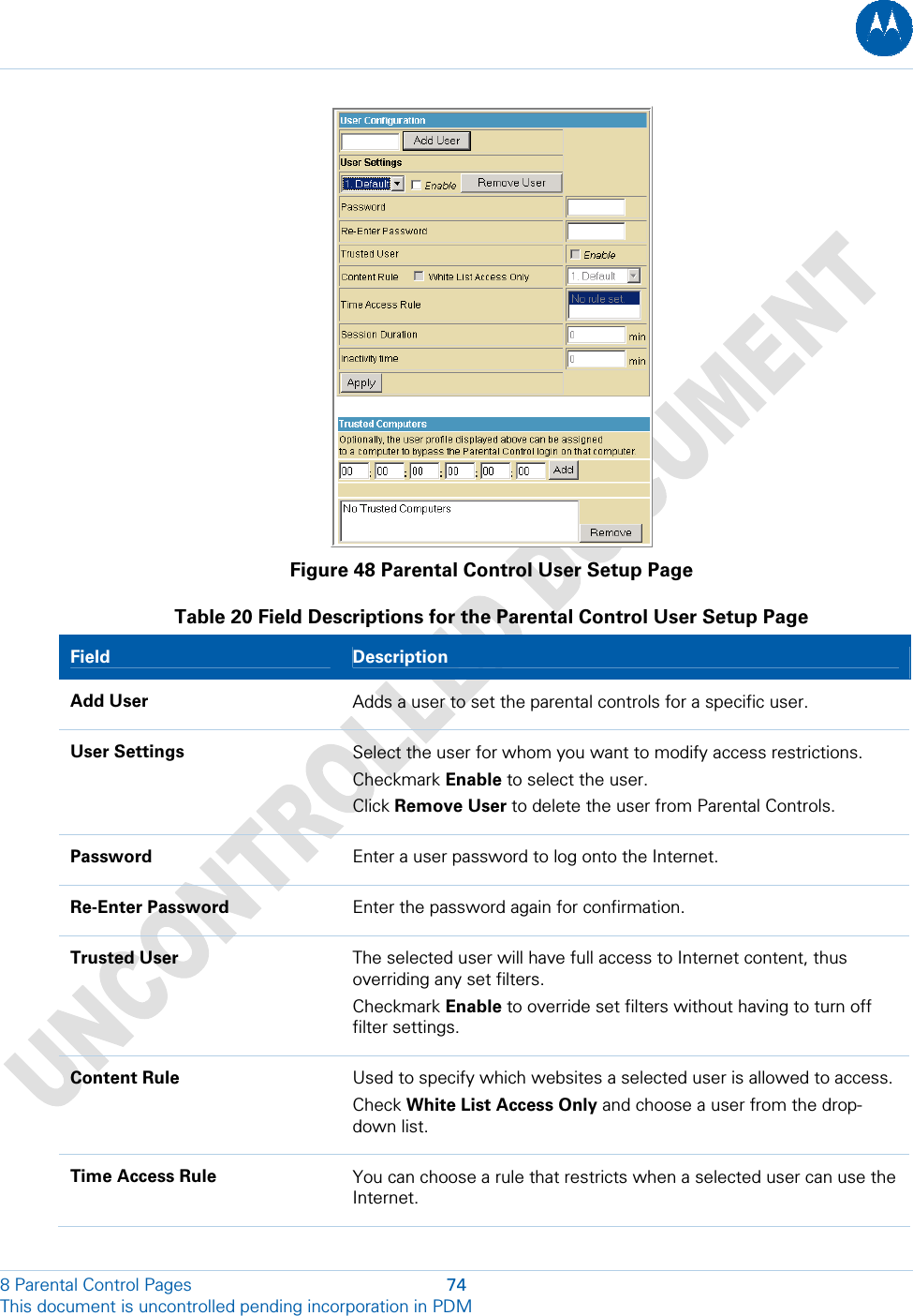
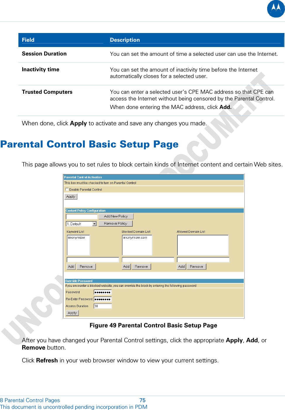
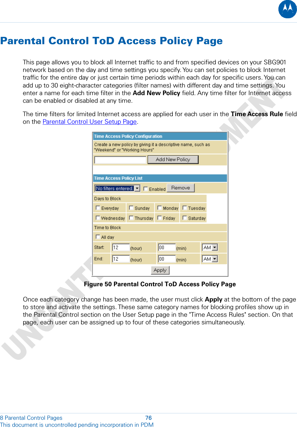
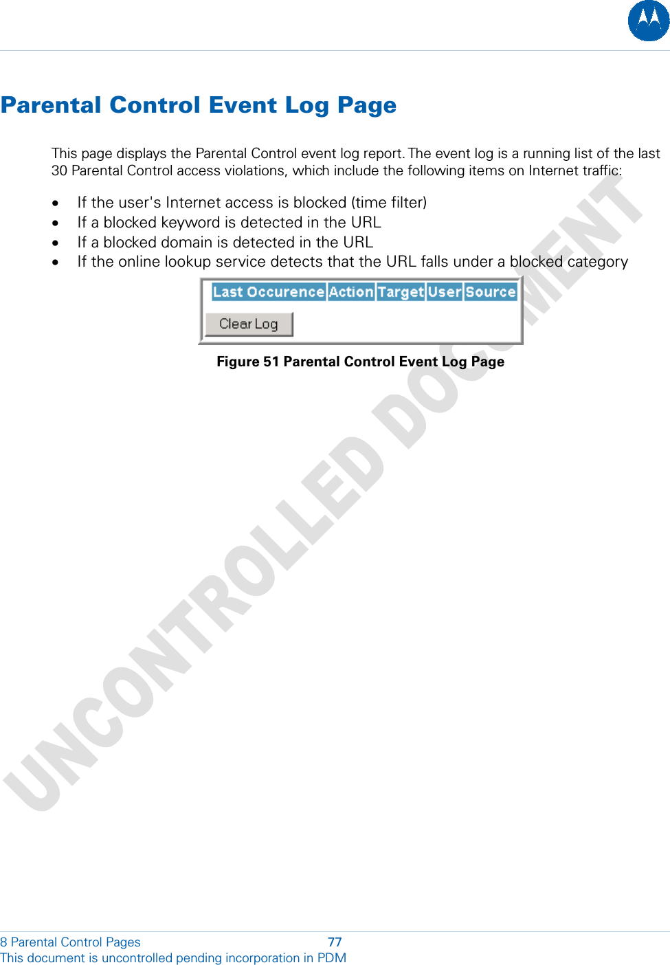
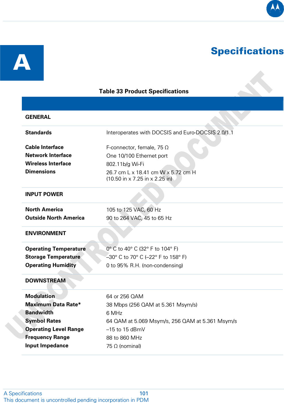
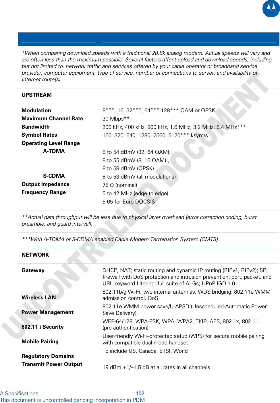
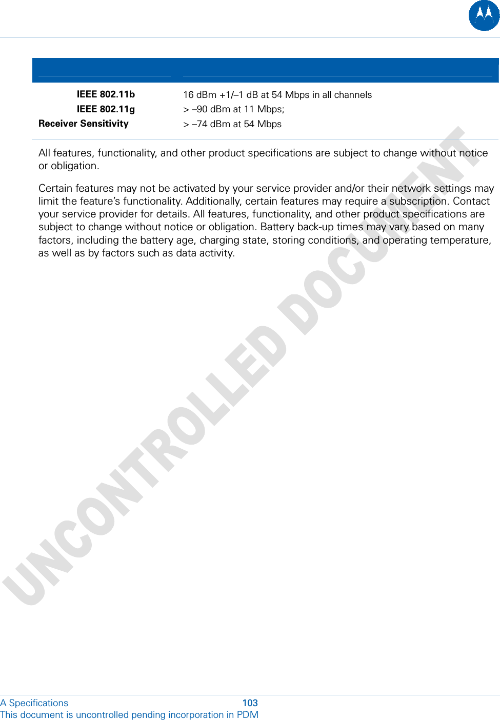
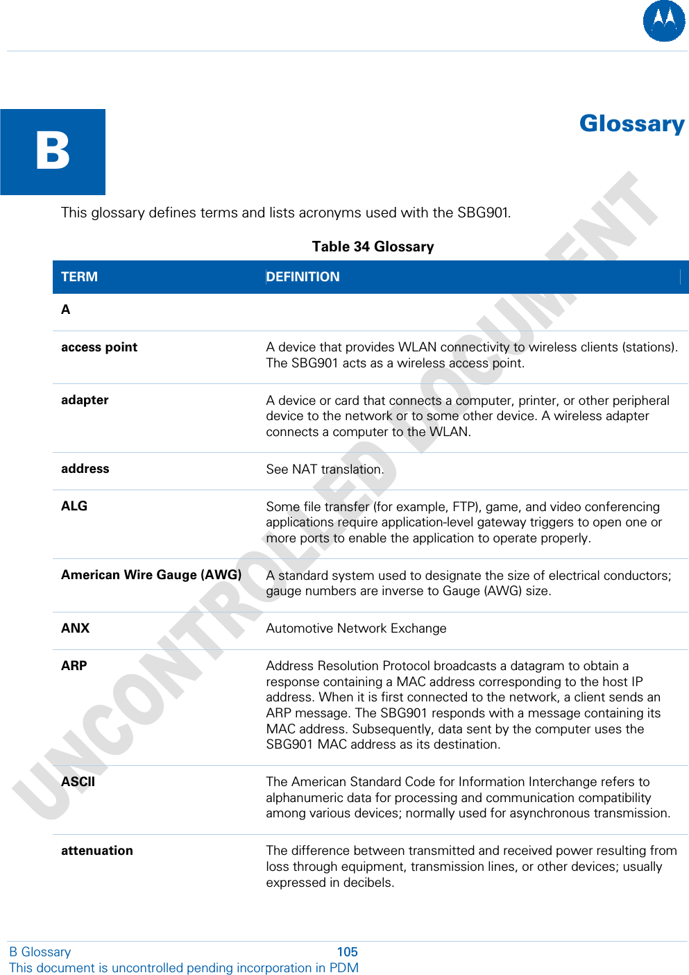
SBG901 User Manual
Manual
Navigation menu
Upload a User Manual
Namespaces
Wiki Guide
HTML
PDF
Info
Views
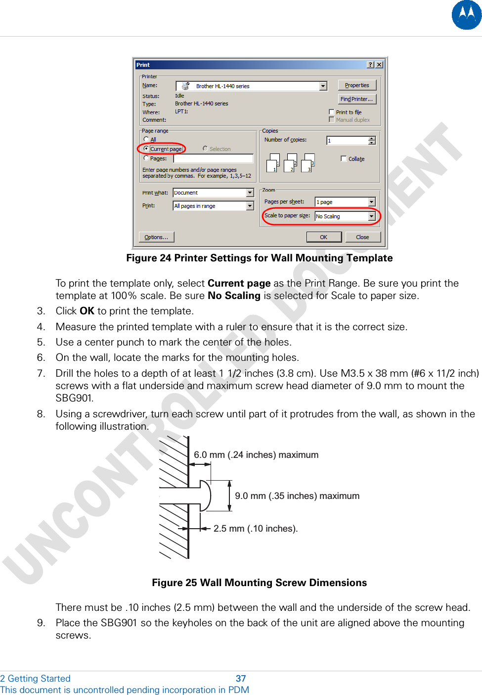
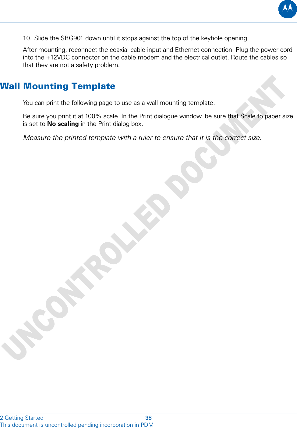
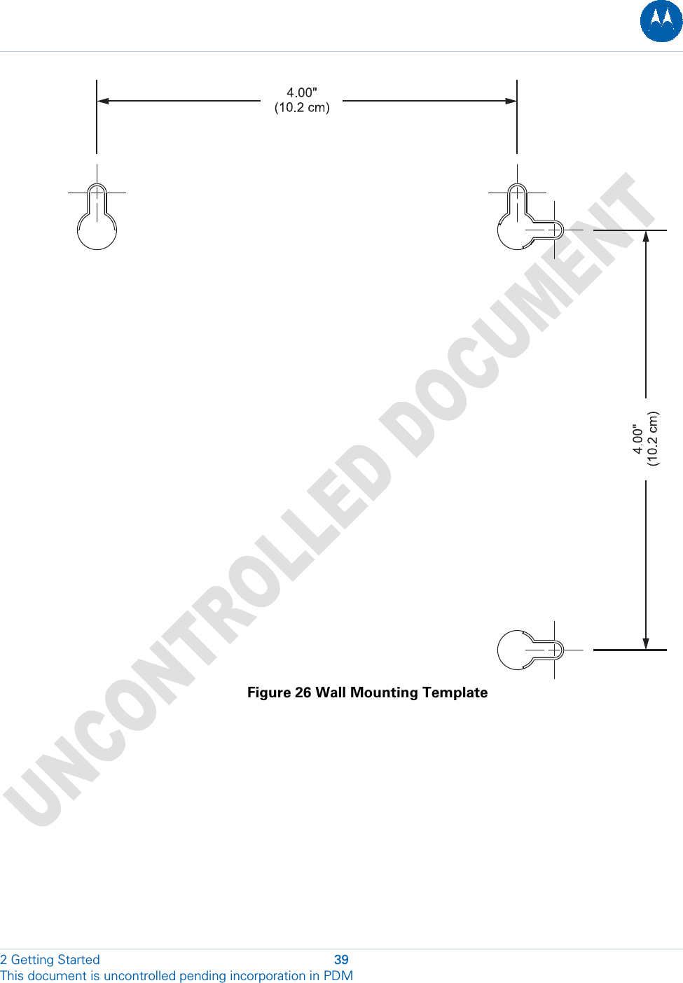
User Manual
Discussion / Help
Navigation