ARRIS SBG940-1 Wireless Cable Modem Gateway User Manual SBG940User
ARRIS Group, Inc. Wireless Cable Modem Gateway SBG940User
ARRIS >
Contents
- 1. User Manual Part 1
- 2. User Manual Part 2
User Manual Part 1
User Guide
SBG940
Wireless Cable
Modem Gateway

ii SBG940 User Guide
Home
X
ExitPrint
Overview Installation Troubleshooting Contact FAQ Specifications Glossary License
Configuration: Basic Gateway TCP/IP Wireless USB
WARNING: TO PREVENT FIRE OR SHOCK HAZARD, DO NOT EXPOSE THIS PRODUCT TO RAIN OR
MOISTURE. THE UNIT MUST NOT BE EXPOSED TO DRIPPING OR SPLASHING. DO NOT PLACE OBJECTS
FILLED WITH LIQUIDS, SUCH AS VASES, ON THE UNIT.
CAUTION: TO PREVENT ELECTRIC SHOCK, THIS EQUIPMENT MAY REQUIRE A GROUNDING
CONDUCTOR IN THE LINE CORD. CONNECT THE UNIT TO A GROUNDING TYPE AC WALL OUTLET USING
THE POWER CORD SUPPLIED WITH THE UNIT.
CAUTION: THIS PRODUCT WAS QUALIFIED UNDER TEST CONDITIONS THAT INCLUDED THE USE OF
THE SUPPLIED CABLES BETWEEN SYSTEMS COMPONENTS. TO ENSURE REGULATORY AND SAFETY
COMPLIANCE, USE ONLY THE PROVIDED POWER AND INTERFACE CABLES AND INSTALL THEM PROPERLY.
CAUTION: DIFFERENT TYPES OF CORD SETS MAY BE USED FOR CONNECTIONS TO THE MAIN SUPPLY
CIRCUIT. USE ONLY A MAIN LINE CORD THAT COMPLIES WITH ALL APPLICABLE PRODUCT SAFETY
REQUIREMENTS OF THE COUNTRY OF USE.
CAUTION: INSTALLATION OF THIS PRODUCT MUST BE IN ACCORDANCE WITH NATIONAL WIRING
CODES AND CONFORM TO LOCAL REGULATIONS.
CAUTION: DO NOT OPEN THE UNIT. DO NOT PERFORM ANY SERVICING OTHER THAN THAT CONTAINED
IN THE INSTALLATION AND TROUBLESHOOTING INSTRUCTIONS. REFER ALL SERVICING TO QUALIFIED
SERVICE PERSONNEL.
CAUTION: CHANGES AND MODIFICATIONS NOT EXPRESSLY APPROVED BY MOTOROLA FOR
COMPLIANCE COULD VOID USER’S AUTHORITY TO OPERATE THE EQUIPMENT.
When using this device, basic safety precautions should always be followed to reduce the risk of fire, electric
shock and injury to persons, including the following:
•Read all of the instructions listed here and/or in the user manual before you operate this equipment. Give
particular attention to all safety precautions. Retain the instructions for future reference.
•This device must be installed and used in strict accordance with manufacturer’s instructions as described in
the user documentation that comes with the product.
•Comply with all warning and caution statements in the instructions. Observe all warning and caution symbols
that are affixed to this equipment.
•Comply with all instructions that accompany this equipment.
•Do not overload outlets or extension cords, as this can result in a risk of fire or electric shock. Overloaded AC
outlets, extension cords, frayed power cords, damaged or cracked wire insulation, and broken plugs are
dangerous. They may result in a shock or fire hazard.
•Route power supply cords so that they are not likely to be walked on or pinched by items placed upon or
against them. Pay particular attention to cords where they are attached to plugs and convenience
receptacles, and examine the point where they exit from the product.
•Place this equipment in a location that is close enough to an electrical outlet to accommodate the length of
the power cord.
•Place unit to allow for easy access when disconnecting the power cord of the device from the AC wall outlet.
•Do not connect the plug into an extension cord, receptacle, other outlet unless the plug can be fully inserted
with no part of the blades exposed.
•Place this equipment on a stable surface.

iii SBG940 User Guide
Home
X
ExitPrint
Overview Installation Troubleshooting Contact FAQ Specifications Glossary License
Configuration: Basic Gateway TCP/IP Wireless USB
•Postpone cable modem installation until there is no risk of thunderstorm or lightning activity in the area.
•Avoid using this product during an electrical storm. There may be a risk of electric shock from lightning. For
added protection for this product during a lightning storm, or when it is left unattended and unused for long
periods of time, unplug it from the wall outlet, and disconnect the cable system. This will prevent damage to
the product due to lightning and power surges.
•It is recommended that the customer install an AC surge protector in the AC outlet to which this device is
connected. This is to avoid damaging the equipment by local lightning strikes and other electrical surges.
•Do not cover the device, or block the airflow to the device with any other objects. Keep the device away from
excessive heat and humidity and keep the device free from vibration and dust.
•Wipe the unit with a clean, dry cloth. Never use cleaning fluid or similar chemicals. Do not spray cleaners
directly on the unit or use forced air to remove dust.
•Avoid damaging the cable modem with static by touching the coaxial cable when it is attached to the earth
grounded coaxial cable TV wall outlet.
•Always first touch the coaxial cable connector on the cable modem when disconnecting or re-connecting USB
or Ethernet cable from the cable modem or the user’s PC.
•Operate this product only from the type of power source indicated on the product’s marking label. If you are
not sure of the type of power supplied to your home, consult your dealer or local power company.
•Upon completion of any service or repairs to this product, ask the service technician to perform safety checks
to determine that the product is in safe operating condition.
Be sure that the outside cable system is grounded, so as to provide some protection against voltage surges and
built-up static charges. Article 820-20 of the NEC (Section 54, Part I of the Canadian Electrical Code) provides
guidelines for proper grounding and, in particular, specifies the CATV cable ground shall be connected in the
grounding system of the building, as close to the point of cable entry as practical.
Apparaten skall anslutas till jordat uttag när den ansluts ett näverk.
FCC Compliance Class B Digital Device
This device complies with part 15 of the FCC Rules. Operation is subject to the following two conditions: (1) This
device may not cause harmful interference, and (2) this device must accept any interference received, including
interference that may cause undesired operation.
Note: This equipment has been tested and found to comply with the limits for a Class B digital device, pursuant to
part 15 of the FCC Rules. These limits are designed to provide reasonable protection against harmful interference
in a residential installation. This equipment generates, uses and can radiate radio frequency energy and, if not
installed and used in accordance with the instructions, may cause harmful interference to radio communications.
However, there is no guarantee that interference will not occur in a particular installation. If this equipment does
cause harmful interference to radio or television reception, which can be determined by turning the equipment off
and on, the user is encouraged to try to correct the interference by one or more of the following measures:
•Reorient or relocate the receiving antenna.
•Increase the separation between the equipment and receiver.
•Connect the equipment into an outlet on a circuit different from that to which the receiver is connected.
•Consult the dealer or an experienced radio/TV technician for help.

iv SBG940 User Guide
Home
X
ExitPrint
Overview Installation Troubleshooting Contact FAQ Specifications Glossary License
Configuration: Basic Gateway TCP/IP Wireless USB
FCC Certification
This product contains a radio transmitter and accordingly has been certified as compliant with 47 CFR Part 15 of
the FCC Rules for intentional radiators. Products that contain a radio transmitter are labeled with FCC ID and the
FCC logo.
CAUTION: Exposure to Radio Frequency Radiation.
To comply with the FCC RF exposure compliance requirements, the separation distance between the antenna and
any person’s body (including hands, wrists, feet and ankles) must be at least 20 cm (8 inches).
Canada - Industry Canada (IC)
The wireless radio of this device complies with RSS 210 and RSS 102 of Industry Canada.
This Class B digital device complies with Canadian ICES-003.
Cet appareil numérique de la classe B est conforme à la norme NMB-003 du Canada.
To prevent radio interference to the licensed service, this device is intended to be operated indoors and away from
windows to provide maximum shielding. Equipment (or its transmit antenna) that is installed outdoors is subject to
licensing.
Only use the antenna(s) provided with this product or an antenna approved by Motorola.
Regulatory, Safety, Software License, and Warranty Information Card
This product is provided with a separate Regulatory, Safety, Software License, and Warranty Information card. If
one is not provided with this product, please ask your service provider or point-of-purchase representative, as the
case may be.
•THIS PRODUCT IS IN COMPLIANCE WITH ONE OR MORE OF THE STANDARDS LISTED ON THE
REGULATORY, SAFETY, SOFTWARE LICENSE, AND WARRANTY INFORMATION CARD. NOT ALL
STANDARDS APPLY TO ALL MODELS.
•NO WARRANTIES OF ANY KIND ARE PROVIDED BY MOTOROLA WITH RESPECT TO THIS PRODUCT,
EXCEPT AS STATED ON THE REGULATORY, SAFETY, SOFTWARE LICENSE, AND WARRANTY
INFORMATION CARD. MOTOROLA’S WARRANTIES DO NOT APPLY TO PRODUCT THAT HAS BEEN
REFURBISHED OR REISSUED BY YOUR SERVICE PROVIDER.
Copyright © 2004 by Motorola, Inc.
All rights reserved. No part of this publication may be reproduced in any form or by any means or used to make any derivative work (such as
translation, transformation or adaptation) without written permission from Motorola, Inc.
Motorola reserves the right to revise this publication and to make changes in content from time to time without obligation on the part of Motorola
to provide notification of such revision or change. Motorola provides this guide without warranty of any kind, either implied or expressed,
including, but not limited to, the implied warranties of merchantability and fitness for a particular purpose. Motorola may make improvements or
changes in the product(s) described in this manual at any time.
MOTOROLA and the Stylized M Logo are registered in the US Patent & Trademark Office. Microsoft, Windows, Windows Me, Windows NT, and
Xbox are registered trademarks and
Windows XP and Xbox Live are trademarks of
Microsoft Corporation. Microsoft Windows screen shots are
used by permission of Microsoft Corporation.
Macintosh and AppleTalk are registered
trademarks
of Apple Computer, Inc. Iomega is a registered
trademark of Iomega Corporation. Linux is a registered trademark of Linus Torvalds. Acrobat Reader is a registered trademark of Adobe Systems,
Inc. Netscape and Navigator are registered trademarks of
Netscape Communications Corporation
. PlayStation is a registered trademark of
Sony
Computer Entertainment Inc.
UNIX is a registered trademark of the Open Group in the United States and other countries. Wi-Fi is a registered
trademark of the Wi-Fi Alliance. All other
product or service names are the property of their respective owners.

vSBG940 User Guide
Home
X
ExitPrint
Overview Installation Troubleshooting Contact FAQ Specifications Glossary License
Configuration: Basic Gateway TCP/IP Wireless USB
Contents
Overview . . . . . . . . . . . . . . . . . . . . . . . . . . . 1
Easy Setup . . . . . . . . . . . . . . . . . . . . . . . . . . . . . . . . . . . 2
Network Connection Types . . . . . . . . . . . . . . . . . . . . . . 2
Powerful Features in a Single Unit . . . . . . . . . . . . . . . . . 2
Sample Hybrid LAN . . . . . . . . . . . . . . . . . . . . . . . . . . . . 3
Optional Accessories . . . . . . . . . . . . . . . . . . . . . . . . . . . 4
Front Panel . . . . . . . . . . . . . . . . . . . . . . . . . . . . . . . . . . 5
Rear Panel . . . . . . . . . . . . . . . . . . . . . . . . . . . . . . . . . . . 6
Label on the Bottom of the SBG940 . . . . . . . . . . . . . . . 7
SBG940 LAN Choices . . . . . . . . . . . . . . . . . . . . . . . . . . 7
Wireless LAN . . . . . . . . . . . . . . . . . . . . . . . . . . . . . . . 8
Wired Ethernet LAN . . . . . . . . . . . . . . . . . . . . . . . . . . 9
USB Connection . . . . . . . . . . . . . . . . . . . . . . . . . . . . 11
Security . . . . . . . . . . . . . . . . . . . . . . . . . . . . . . . . . . . . 12
Firewall . . . . . . . . . . . . . . . . . . . . . . . . . . . . . . . . . . . 12
DMZ . . . . . . . . . . . . . . . . . . . . . . . . . . . . . . . . . . . . . 13
Port Triggering . . . . . . . . . . . . . . . . . . . . . . . . . . . . . 13
Wireless Security . . . . . . . . . . . . . . . . . . . . . . . . . . . 13
Port Forwarding . . . . . . . . . . . . . . . . . . . . . . . . . . . . . . 14
Virtual Private Networks . . . . . . . . . . . . . . . . . . . . . . . . 14
Related Documentation . . . . . . . . . . . . . . . . . . . . . . . . 14
Installation. . . . . . . . . . . . . . . . . . . . . . . . . 15
Before You Begin . . . . . . . . . . . . . . . . . . . . . . . . . . . . . 15
Precautions . . . . . . . . . . . . . . . . . . . . . . . . . . . . . . . . . 16
Signing Up for Service . . . . . . . . . . . . . . . . . . . . . . . . . 16
Computer System Requirements . . . . . . . . . . . . . . . . . 17
Connecting the SBG940 to the Cable System . . . . . . . 18
Cabling the LAN . . . . . . . . . . . . . . . . . . . . . . . . . . . . . . 18
Obtaining an IP Address for Ethernet . . . . . . . . . . . . . 19
Obtaining an IP Address in Windows 98,
Windows 98 SE, or Windows Me . . . . . . . . . . . . . . . 19
Obtaining an IP Address in Windows 2000 or
Windows XP . . . . . . . . . . . . . . . . . . . . . . . . . . . . . . . 19
Obtaining an IP Address on Macintosh or UNIX
Systems . . . . . . . . . . . . . . . . . . . . . . . . . . . . . . . . . . 19
Connecting a PC to the USB Port . . . . . . . . . . . . . . . . 20
Wall Mounting . . . . . . . . . . . . . . . . . . . . . . . . . . . . . . . 21
Wall Mounting Template . . . . . . . . . . . . . . . . . . . . . 23
Basic Configuration . . . . . . . . . . . . . . . . . 24
Starting the SBG940 Setup Program . . . . . . . . . . . . . . 25
Changing the Default Password . . . . . . . . . . . . . . . . . 27
Enabling Remote Access . . . . . . . . . . . . . . . . . . . . . . . 28
Getting Help . . . . . . . . . . . . . . . . . . . . . . . . . . . . . . . . . 29
Setting the Firewall Policy . . . . . . . . . . . . . . . . . . . . . . 30
Firewall > POLICY — advanced Page . . . . . . . . . . 32
Firewall > ALERT — basic Page . . . . . . . . . . . . . . . 34
Firewall > ALERT — email Page . . . . . . . . . . . . . . . 35
Firewall > LOGS Page . . . . . . . . . . . . . . . . . . . . . . 36
Gaming Configuration Guidelines . . . . . . . . . . . . . . . . 37
Configuring the Firewall for Gaming . . . . . . . . . . . . 37
Configuring Port Triggers . . . . . . . . . . . . . . . . . . . . 37
Configuring a Gaming DMZ Host . . . . . . . . . . . . . . 38
Configuring the Gateway . . . . . . . . . . . . . 39
Gateway > STATUS Page . . . . . . . . . . . . . . . . . . . . . 40
Gateway > WAN Page . . . . . . . . . . . . . . . . . . . . . . . . 41
Gateway > LAN — nat config Page . . . . . . . . . . . . . . 43
Gateway > LAN — dhcp server config Page . . . . . . . . 44
Gateway > LAN — dhcp leases Page . . . . . . . . . . . . . 45
Gateway > PORT FORWARDING — status Page . . . 46
Gateway > PORT FORWARDING — config Page . . . 47
Gateway > PORT TRIGGERS — predefined Page . . 48
Gateway > PORT TRIGGERS — custom Page . . . . . 50
Gateway > LOG Page . . . . . . . . . . . . . . . . . . . . . . . . . 51
Configuring TCP/IP . . . . . . . . . . . . . . . . . . 52
Configuring TCP/IP in Windows 95, Windows 98, or
Windows Me . . . . . . . . . . . . . . . . . . . . . . . . . . . . . . . . 52
Configuring TCP/IP in Windows 2000 . . . . . . . . . . . . . 55
Configuring TCP/IP in Windows XP . . . . . . . . . . . . . . 59
Verifying the IP Address in Windows 95, Windows 98,
or Windows Me . . . . . . . . . . . . . . . . . . . . . . . . . . . . . . 63
Verifying the IP Address in Windows 2000 or Windows XP .64
Setting Up Your Wireless LAN. . . . . . . . . 66
Encrypting Wireless LAN Transmissions . . . . . . . . . . 67
Configuring WPA on the SBG940 . . . . . . . . . . . . . . 68
Configuring WEP on the SBG940 . . . . . . . . . . . . . . 70
Restricting Wireless LAN Access . . . . . . . . . . . . . . . . 72
Configuring the Wireless Network Name on
the SBG940 . . . . . . . . . . . . . . . . . . . . . . . . . . . . . . . 73
Configuring a MAC Access Control List on the SBG940 .75
Configuring the Wireless Clients . . . . . . . . . . . . . . . . . 76
Configuring a Wireless Client for WPA . . . . . . . . . . 77
Configuring a Wireless Client for WEP . . . . . . . . . . 77
Configuring a Wireless Client with the Network
Name (ESSID) . . . . . . . . . . . . . . . . . . . . . . . . . . . . . 77

vi SBG940 User Guide
Home
X
ExitPrint
Overview Installation Troubleshooting Contact FAQ Specifications Glossary License
Configuration: Basic Gateway TCP/IP Wireless USB
Wireless Pages in the SBG940 Setup Program . . . . . .78
Wireless > STATUS Page . . . . . . . . . . . . . . . . . . . . 79
Wireless > NETWORK Page . . . . . . . . . . . . . . . . . . 80
Wireless > SECURITY — basic Page . . . . . . . . . . . 82
Wireless > SECURITY — advanced Page . . . . . . . . 83
Wireless > STATISTICS page . . . . . . . . . . . . . . . . . 84
Setting Up a USB Driver . . . . . . . . . . . . . . 86
Setting Up a USB Driver in Windows 98 . . . . . . . . . . . 87
Setting Up a USB Driver in Windows 2000 . . . . . . . . . 91
Setting Up a USB Driver in Windows Me . . . . . . . . . . . 94
Setting Up a USB Driver in Windows XP . . . . . . . . . . . 95
Removing the USB Driver from Windows 98 or
Windows Me . . . . . . . . . . . . . . . . . . . . . . . . . . . . . . . . . 96
Removing the USB Driver from Windows 2000 . . . . . . 99
Removing the USB Driver from Windows XP . . . . . . .102
Troubleshooting . . . . . . . . . . . . . . . . . . . 107
Front-Panel Lights and Error Conditions . . . . . . . . . . 108
Contact Us . . . . . . . . . . . . . . . . . . . . . . . . 109
Frequently-Asked Questions . . . . . . . . . 110
Specifications . . . . . . . . . . . . . . . . . . . . . 112
Glossary. . . . . . . . . . . . . . . . . . . . . . . . . . 114
Software License . . . . . . . . . . . . . . . . . . 132
1SBG940 User Guide
Home
X
ExitPrint
Overview Installation Troubleshooting Contact FAQ Specifications Glossary License
Configuration: Basic Gateway TCP/IP Wireless USB
Overview
Thank you for purchasing a Motorola® SURFboard® Wireless Cable Modem Gateway SBG940 for your home,
home office, or small business/enterprise. Applications where the SURFboard Gateway (SBG) is especially useful
include:
•Households having multiple computers requiring connection to the Internet and each other
•Small businesses or home offices requiring fast, affordable, and secure Internet access
•Internet gamers desiring easier setup for:
— Programs such as DirectX® 7 or DirectX® 8
— Sites such as MSN Games by Zone.com or Battle.net®
•Video conferencing
A home network enables you to share information between two or more computers. You can connect your home
network to the Internet through the cable TV system. The SBG940 is the central connection point between your
computers and the Internet. It directs (routes) information between the computers connected to your home
network. A built-in cable modem transmits information between your home network and the Internet. An SBG940:
•Combines four separate products — a DOCSIS® cable modem, IEEE 802.11g wireless access point,
Ethernet 10/100Base-T connections, and firewall — into one compact unit
•Enables you to create a custom network sharing a single broadband connection, files, and peripherals, with
or without wires
•Has an advanced firewall for enhanced network security for wired and wireless users
•Provides easy setup
This product is subject to change. Not all features described in this guide are available on all SBG940 models.
For the most recent documentation, visit the Cable Modems and Gateways page on the Motorola Broadband
website http://broadband.motorola.com/.
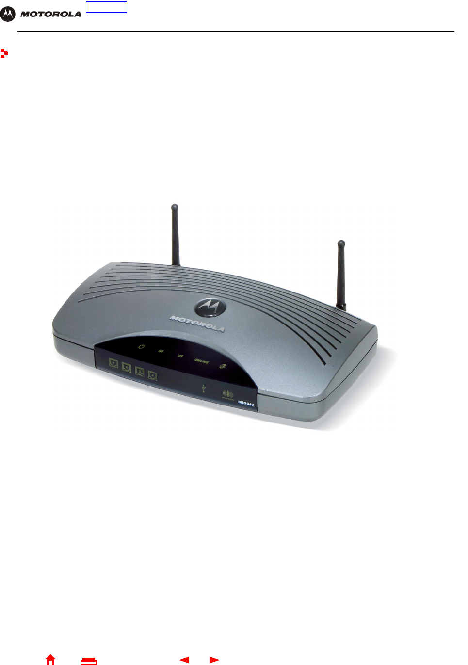
The features and physical appearance of your SBG940 may differ slightly from the picture.

2SBG940 User Guide
Home
X
ExitPrint
Overview Installation Troubleshooting Contact FAQ Specifications Glossary License
Configuration: Basic Gateway TCP/IP Wireless USB
Easy Setup
It is much easier to configure a local area network (LAN) using an SBG940 than using traditional networking
equipment:
•For basic operation, most default settings require no modification.
•The Setup Program provides a graphical user interface (GUI) for easy configuration of necessary wireless,
Ethernet, router, DHCP, and security settings. For information about using the Setup Program, see “Basic
Configuration”.
Network Connection Types
The SBG940 provides different network connection types for your computers to exchange data. The connection
between your computers and the SBG940 may be with a wireless or a wired connection or a combination of the
two. Your network can use one or any combination of all the following network connections:
•Ethernet local area network (LAN)
•Wireless LAN (IEEE 802.11g that also supports IEEE 802.11b wireless clients)
•Universal Serial Bus (USB)
Powerful Features in a Single Unit
An SBG940 combines high-speed Internet access, networking, and computer security for a home or small-office
LAN. An SBG940 provides:
•An integrated high-speed SURFboard cable modem for continuous broadband access to the Internet and
other online services, with much faster data transfer than traditional dial-up or ISDN modems
•A single broadband connection for up to 253 computers to surf the web; all computers on the LAN
communicate as if they were connected to the same physical network
•An IEEE 802.11g wireless access point to enable laptop users to remain connected while moving around the
home or small office or to connect desktop computers without installing network wiring. Depending on
distance, wireless connection speeds can match that of Ethernet.
•A USB connection for a single PC
•Four 10/100Base-T Ethernet uplink ports supporting half- or full-duplex connections and Auto-MDIX
•Routing for a wireless LAN (WLAN) or a wired Ethernet LAN; you can connect more than four computers
using hubs and/or switches
•A built-in DHCP server to easily configure a combined wired and/or wireless Class C private LAN
•An advanced firewall supporting stateful-inspection, intrusion detection, DMZ, denial-of-service attack
prevention, and Network Address Translation (NAT)
•Virtual private network (VPN) pass-through operation supporting IPSec, PPTP, or L2TP to securely connect
remote computers over the Internet
•Port Forwarding to configure ports to run applications having special network requirements
3SBG940 User Guide
Home
X
ExitPrint
Overview Installation Troubleshooting Contact FAQ Specifications Glossary License
Configuration: Basic Gateway TCP/IP Wireless USB
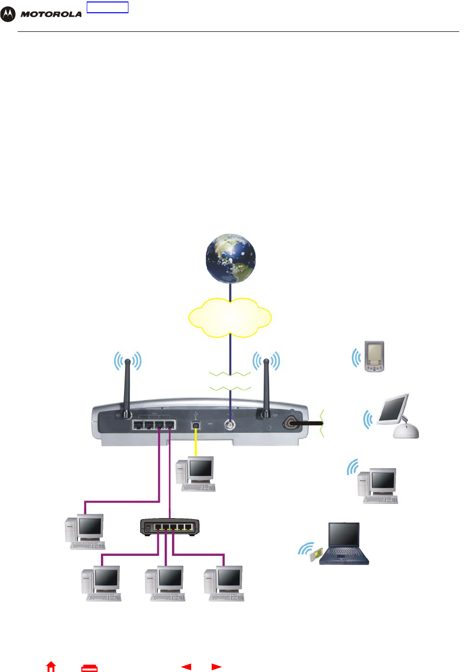
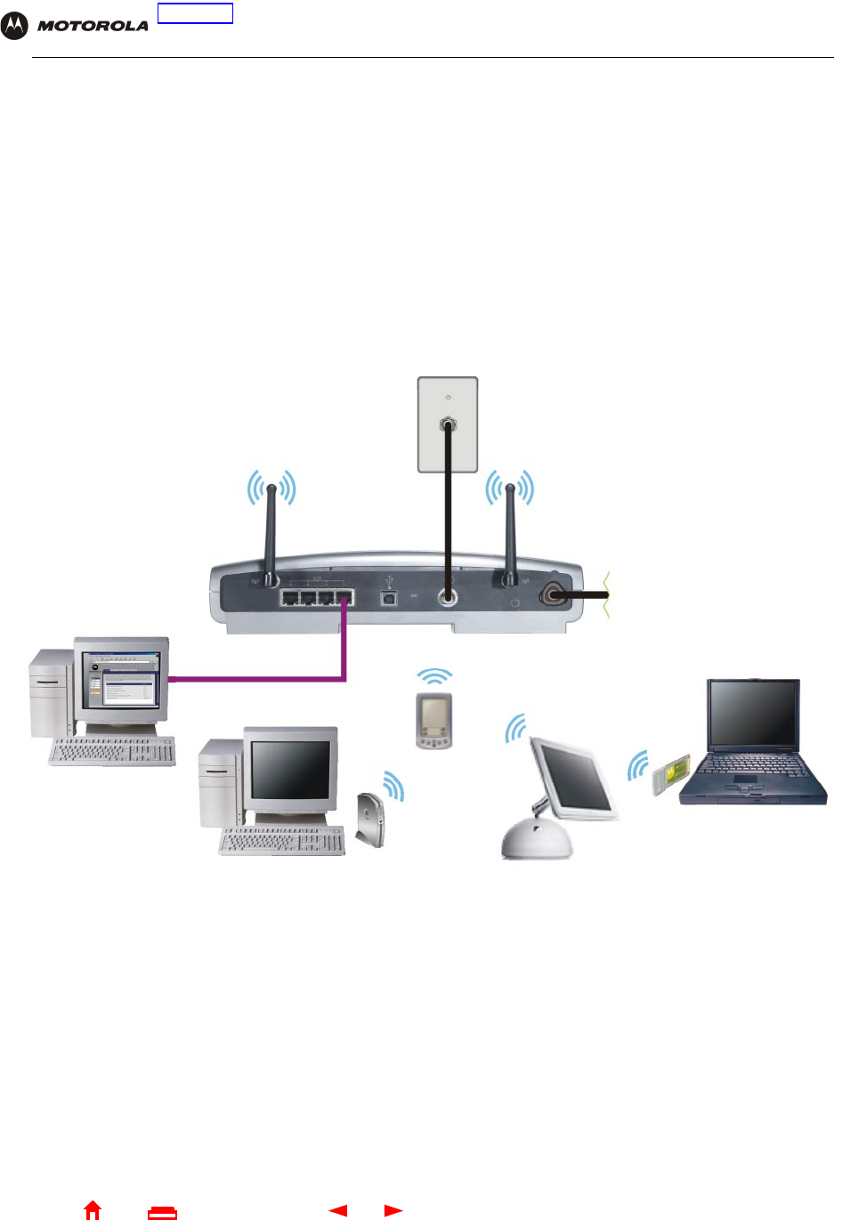
Sample Hybrid LAN
The sample LAN illustrated on this page contains the following devices, all protected by the SBG940 firewall
Clockwise from top-right, the devices are:
•A PDA on a wireless connection
•One desktop Apple Macintosh® computer on a wireless connection
•One desktop PC on a wireless connection using a Motorola Wireless PCI Adapter
•A laptop PC on a wireless connection using a Motorola Wireless Notebook Adapter
•One PC connected to the USB port
•Three computers connected to Ethernet port one using a hub or switch
•One computer connected directly to Ethernet port two
Internet
High-speed HFC
cable network
Wireless
Firewall
Ethernet
Hub or switch
SBG940 USB
To A C
power
4SBG940 User Guide
Home
X
ExitPrint
Overview Installation Troubleshooting Contact FAQ Specifications Glossary License
Configuration: Basic Gateway TCP/IP Wireless USB
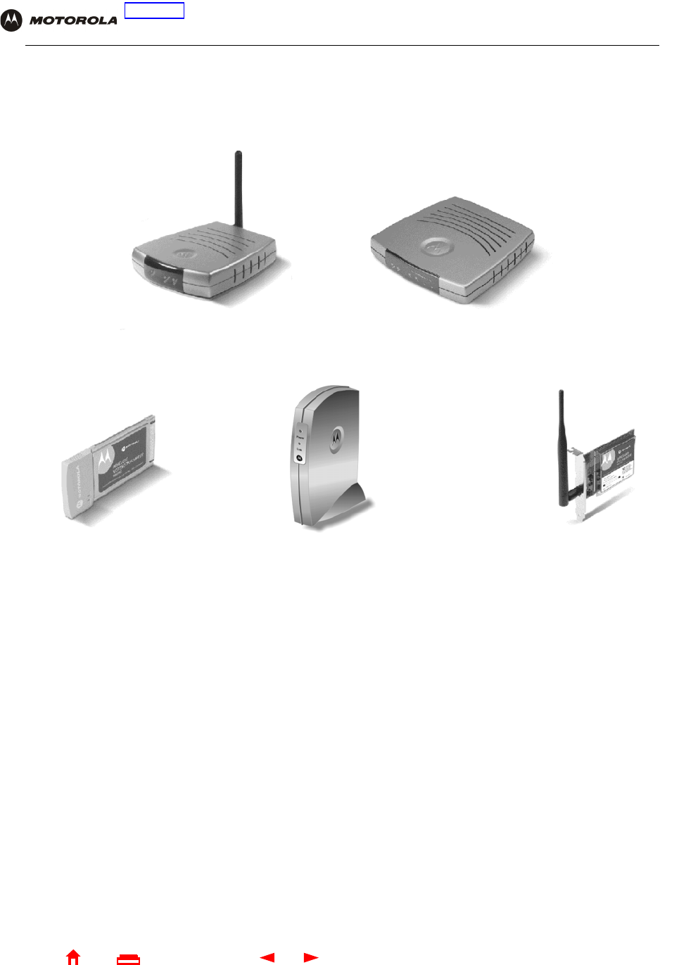
Optional Accessories
All networks are composed of multiple devices. The SBG940 works with any IEEE 802.11g or IEEE 802.11b
compliant client product. Motorola supplies a range of accessories for use with the SBG940. Some examples are:
For up-to-date information about accessories and home networking options, including product documentation,
visit the Motorola Home Networking page http://broadband.motorola.com/consumers/home_networking.asp.
Wireless Ethernet
Bridge WE800G
Ethernet Broadband
Router BR700
Wireless Notebook
Adapter WN825G
Wireless PCI Adapter
WPCI810G
Wireless USB
Adapter WU830G
5SBG940 User Guide
Home
X
ExitPrint
Overview Installation Troubleshooting Contact FAQ Specifications Glossary License
Configuration: Basic Gateway TCP/IP Wireless USB
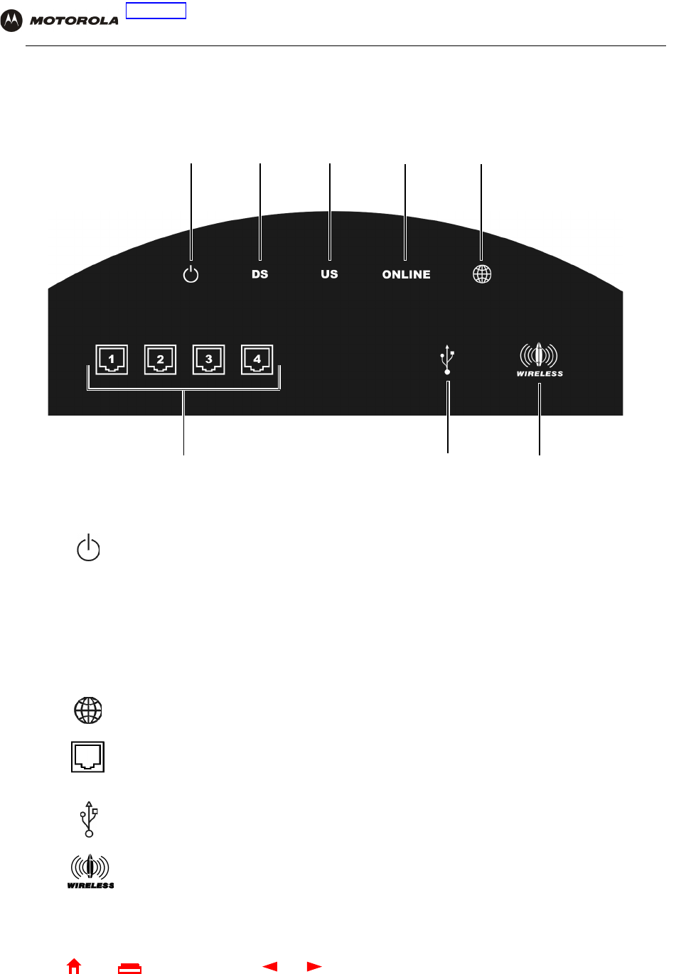
Front Panel
The front panel provides indicator lights. The display is dark unless there is a connection or activity on an
interface:
Key Light Flashing On
1Never flashes The AC power is connected properly
2DS Scanning for a receive (downstream)
channel connection
The downstream channel is connected
3US Scanning for a send (upstream) channel
connection
The upstream channel is connected
4ONLINE Scanning for a network connection The startup process is complete and the SBG940
is online
5Transmitting or receiving data over
the Internet
Is never lit solid
6Ethernet activity on the port (1 to 4) There is a connection to the port (1 to 4):
•Green for 100Base-T
•Yellow for 10Base-T
7USB activity Lights green if there is a proper USB connection
8Wireless activity The wireless interface is on (Enable Wireless
Interface is selected on the Wireless > NETWORK
Page in the SBG940 Setup Program)
123 4
68
5
7
6SBG940 User Guide
Home
X
ExitPrint
Overview Installation Troubleshooting Contact FAQ Specifications Glossary License
Configuration: Basic Gateway TCP/IP Wireless USB
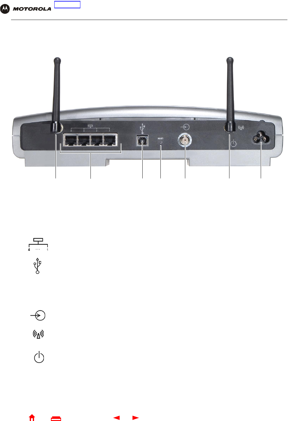
Rear Panel
The rear panel provides cabling connectors, status lights, and the power receptacle:
Key Item Description
1An adjustable, but non-removable antenna. Do not attempt to force this antenna off the unit.
2Use any Ethernet port to connect an Ethernet LAN cable with RJ-45 connectors to an
Ethernet-equipped computer, hub, bridge, switch or Xbox or PlayStation® 2 gaming console.
3For Windows only, use the USB port for Connecting a PC to the USB Port. You cannot connect the
SBG940 USB port to a Macintosh or UNIX® computer.
4 RESET If you experience a problem, you can push this recessed button to restart the SBG940 (see
“Troubleshooting”). To reset all values to their defaults, hold down the button for more than five
seconds. Resetting may take 5 to 30 minutes because the SBG940 must find and lock on the
appropriate communications channels.
5Use the cable connector to connect to the coaxial cable outlet.
6Removable, adjustable antenna. If necessary, contact your cable provider about obtaining an optional
Motorola wireless high gain antenna to increase WLAN performance and coverage.
7Use the AC connector to connect to the AC power outlet.
2345671
7SBG940 User Guide
Home
X
ExitPrint
Overview Installation Troubleshooting Contact FAQ Specifications Glossary License
Configuration: Basic Gateway TCP/IP Wireless USB
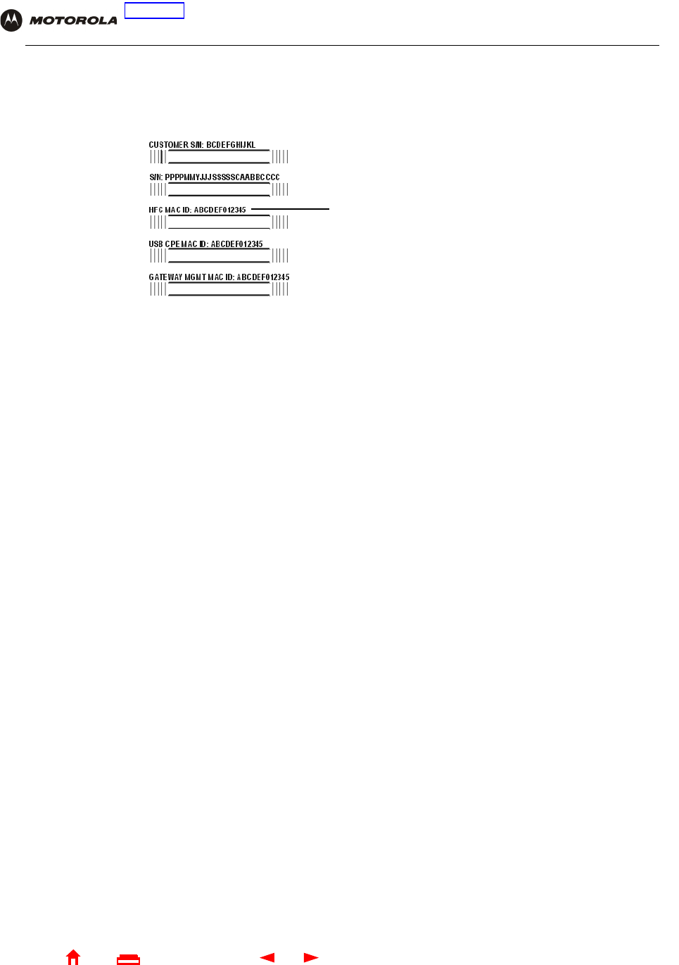
Label on the Bottom of the SBG940
To receive data service, you need to provide the MAC address marked HFC MAC ID to your cable provider:
SBG940 LAN Choices
The SBG940 enables you to connect up to 253 client computers on a combination of:
•Wireless LAN
•Wired Ethernet LAN
•USB Connection
Each computer needs appropriate network adapter hardware and driver software. The clients on the Ethernet,
wireless, or USB interfaces can share:
•Internet access with a single cable provider account, subject to cable provider terms and conditions
•Files, printers, storage devices, multi-user software applications, games, and video conferencing
Wireless and wired network connections use Windows networking to share files and peripheral devices such as
printers, CD-ROM drives, floppy disk drives, and Iomega® Zip Drives.
HFC MAC ID
8SBG940 User Guide
Home
X
ExitPrint
Overview Installation Troubleshooting Contact FAQ Specifications Glossary License
Configuration: Basic Gateway TCP/IP Wireless USB
Wireless LAN
Wireless communication occurs over radio waves rather than a wire. Like a cordless telephone, a WLAN uses
radio signals instead of wires to exchange data. A wireless network eliminates the need for expensive and
intrusive wiring to connect computers throughout the home or office. Mobile users can remain connected to the
network even when carrying their laptop to different locations in the home or office.
Each computer on a WLAN requires a wireless adapter shown in “Optional Accessories”:
Sample wireless network connections
To set up the SBG940, on a computer wired to the SBG940 over Ethernet or USB, perform the procedures in
“Setting Up Your Wireless LAN”. Do not attempt to configure the SBG940 over a wireless connection.
Your maximum wireless operation distance depends on the type of materials through which the signal must pass
and the location of your antennas and clients (stations). Motorola cannot guarantee wireless operation for all
supported distances in all environments.
An optional Motorola high gain antenna can improve wireless performance. For information about available
optional antennas for your SBG940, contact your cable provider.
Laptop PCs Use a Motorola Wireless Notebook Adapter or compatible product in the PCMCIA slot.
Desktop PCs Use a Motorola Wireless PCI Adapter, Wireless USB Adapter, or compatible product in the PCI slot or
USB port, respectively.
Computer with wired
connection used to
run SBG940
Setup Program
SBG940
To A C
power
9SBG940 User Guide
Home
X
ExitPrint
Overview Installation Troubleshooting Contact FAQ Specifications Glossary License
Configuration: Basic Gateway TCP/IP Wireless USB
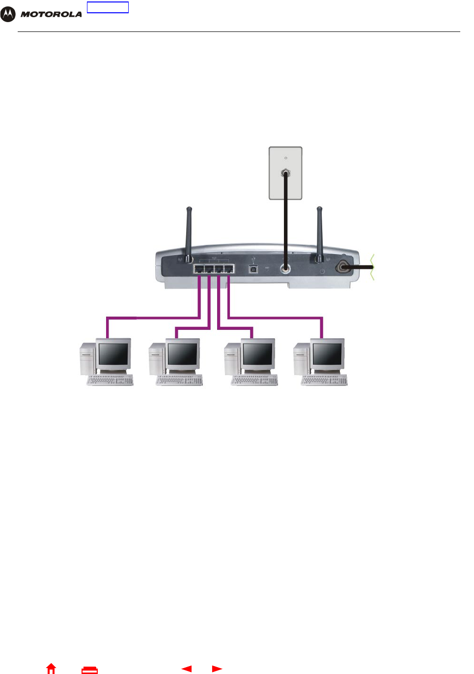
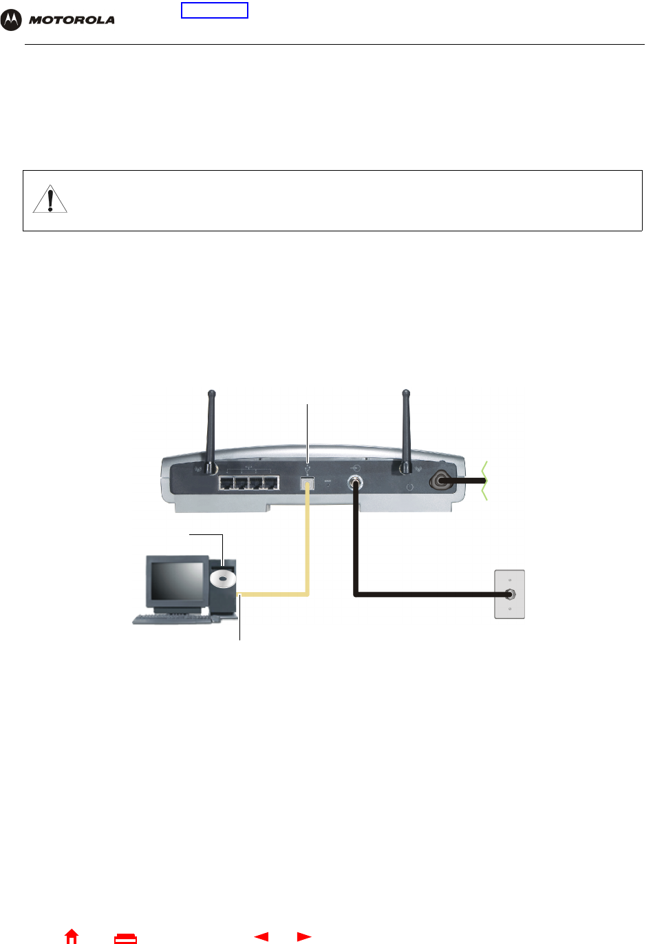
Wired Ethernet LAN
Each computer on the 10/100Base-T Ethernet LAN requires an Ethernet network interface card (NIC) and driver
software installed. Because the SBG940 Ethernet port supports auto-MDIX, you can use straight-through or
cross-over cable to connect a hub, switch, or computer. Use category 5 cabling for all Ethernet connections.
The physical wiring arrangement has no connection to the logical network allocation of IP addresses.
Sample Ethernet to computer connection
Coaxial
cable
Category 5 Ethernet cable
SBG940
To A C
power
10 SBG940 User Guide
Home
X
ExitPrint
Overview Installation Troubleshooting Contact FAQ Specifications Glossary License
Configuration: Basic Gateway TCP/IP Wireless USB
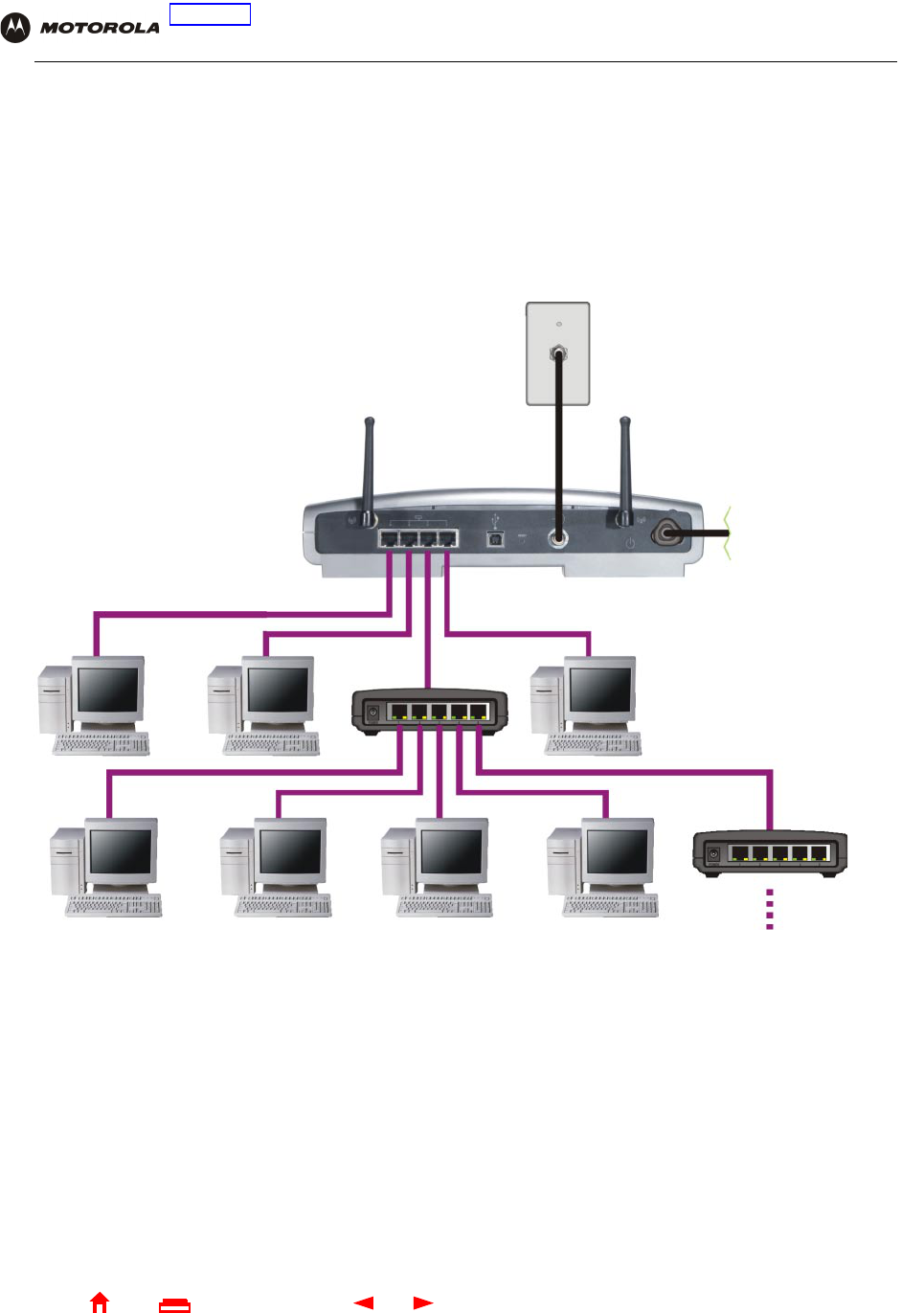
A wired Ethernet LAN with more than four computers requires one or more hubs, switches, or routers. You can:
•Connect a hub or switch to any Ethernet port on the SBG940
•Use Ethernet hubs, switches, or routers to connect up to 253 computers to the SBG940
The following illustration is an example of an Ethernet LAN you can set up using the SBG940. Cable the LAN in an
appropriate manner for the site. A complete discussion of Ethernet cabling is beyond the scope of this document.
Sample Ethernet connection to hubs or switches
Add additional hubs or switches
for further expansion
SBG940
To AC
power
11 SBG940 User Guide
Home
X
ExitPrint
Overview Installation Troubleshooting Contact FAQ Specifications Glossary License
Configuration: Basic Gateway TCP/IP Wireless USB
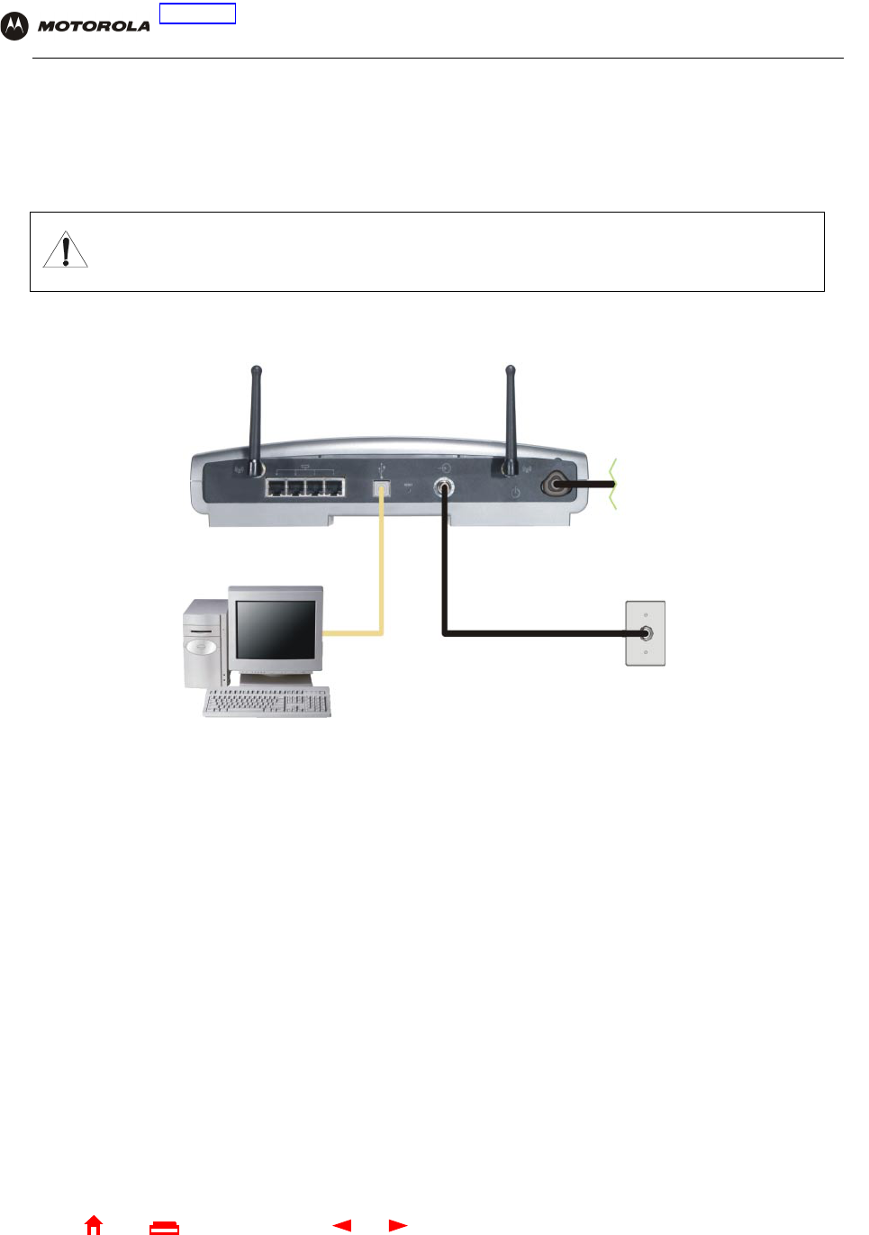
USB Connection
You can connect a single PC running Windows®98, Windows XP™, Windows Me®, or Windows®2000 to the
SBG940 USB V1.1 port. For cabling instructions, see “Connecting a PC to the USB Port”.
Sample USB connection
Caution!
Before plugging in the USB cable, be sure the SBG940 Installation CD-ROM is inserted in the PC
CD-ROM drive.
SBG940
To A C
power
12 SBG940 User Guide
Home
X
ExitPrint
Overview Installation Troubleshooting Contact FAQ Specifications Glossary License
Configuration: Basic Gateway TCP/IP Wireless USB
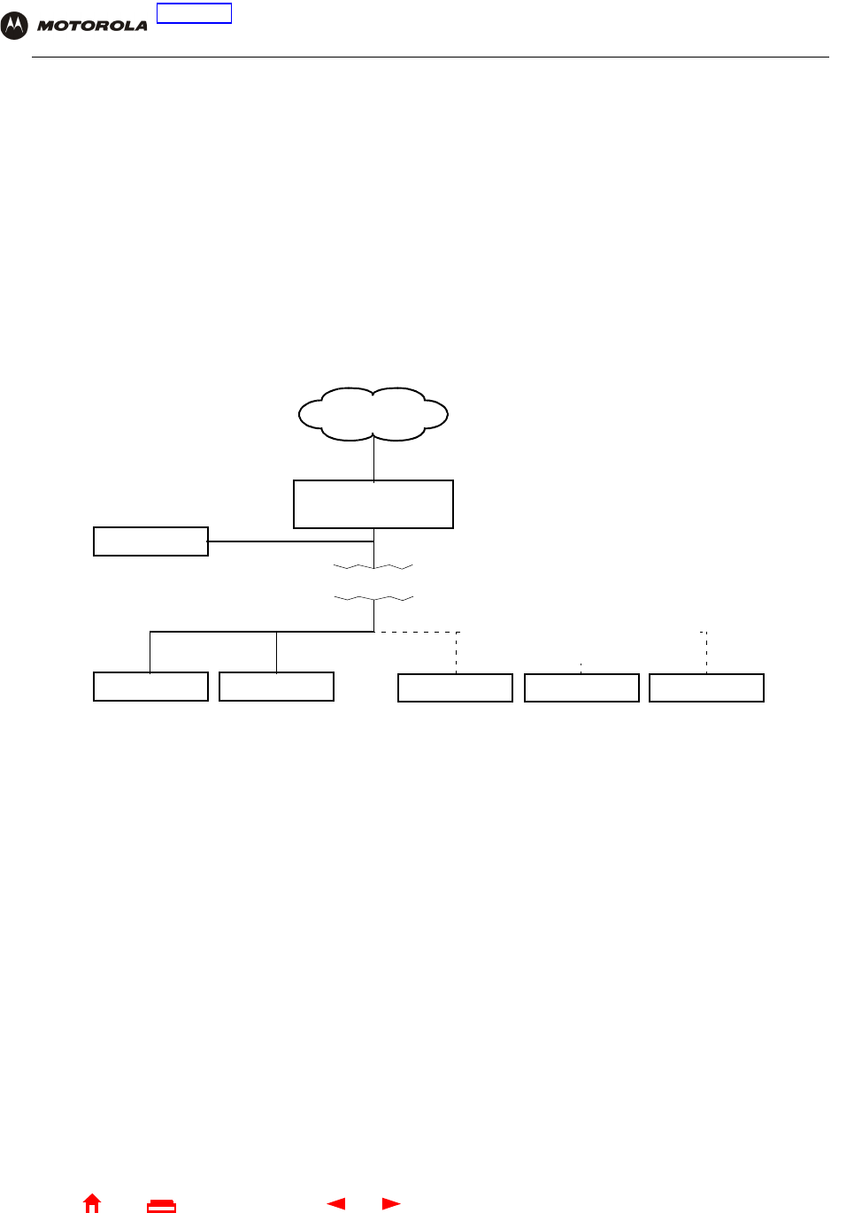
Security
The SBG940 provides:
•A firewall to protect the SBG940 LAN from undesired attacks over the Internet
•For wireless transmissions, data encryption and network access control
Network Address Translation (NAT) provides some security because the IP addresses of SBG940 LAN computers
are not visible on the Internet.
This diagram does not necessarily correspond to the network cabling. A full discussion of network security is
beyond the scope of this document.
SBG940 security measures shown in a logical network diagram
Firewall
The SBG940 firewall protects the SBG940 LAN from undesired attacks and other intrusions from the Internet. It
provides an advanced integrated stateful-inspection firewall supporting intrusion detection, session tracking, and
denial-of-service attack prevention. The firewall:
•Maintains state data for every TCP/IP session on the OSI network and transport layers
•Monitors all incoming and outgoing packets, applies the firewall policy to each one, and screens for improper
packets and intrusion attempts
•Provides comprehensive logging for all:
— User authentications
— Rejected internal and external connection requests
— Session creation and termination
— Outside attacks (intrusion detection)
You can configure the firewall filters to set rules for port usage. For information about choosing a predefined
firewall policy template, see “Setting the Firewall Policy”.
SBG940
Firewall
ComputerComputer
Wired Ethernet LAN Wireless LAN
LaptopComputer PDA
Wireless Security:
Encryption, MAC access control,
or closed network operation
Internet
DMZ computer

13 SBG940 User Guide
Home
X
ExitPrint
Overview Installation Troubleshooting Contact FAQ Specifications Glossary License
Configuration: Basic Gateway TCP/IP Wireless USB
DMZ
A de-militarized zone (DMZ) is one or more computers logically located outside the firewall between an SBG940
LAN and the Internet. A DMZ prevents direct access by outside users to private data.
For example, you can set up a web server on a DMZ computer to enable outside users to access your website
without exposing confidential data on your network.
A DMZ can also be useful to play interactive games that may have a problem running through a firewall. You can
leave a computer used for gaming only exposed to the Internet while protecting the rest of your network. For more
information, see “Gaming Configuration Guidelines”.
Port Triggering
When you run an application that accesses the Internet, it typically initiates communications with a computer on
the Internet. For some applications, especially gaming, the computer on the Internet also initiates communications
with your computer. Because NAT does not normally allow these incoming connections:
•The SBG940 has preconfigured port triggers for common applications.
•If needed, you can configure additional port triggers on the Gateway > PORT TRIGGERS — custom Page.
Wireless Security
Because WLAN data is transmitted using radio signals, it may be possible an unauthorized person to access your
WLAN unless you prevent them from doing so. To prevent unauthorized eavesdropping of data transmitted over
your LAN, you must enable wireless security. The default SBG940 settings neither provide security for
transmitted data nor protect network data from unauthorized intrusions.
The SBG940 provides the following wireless security measures, which are described in “Setting Up Your Wireless
LAN”:
•To prevent unauthorized eavesdropping, you must encrypt data transmitted over the wireless interface using
one of:
— If all of your wireless clients support Wi-Fi® Protected Access (WPA) encryption, we recommend using
WPA (see “Configuring WPA on the SBG940” and “Configuring a Wireless Client for WPA”).
— Otherwise, configure a Wired Equivalency Privacy (WEP) key on the SBG940 and each WLAN client
(see “Configuring WEP on the SBG940” and “Configuring a Wireless Client for WEP”).
•To protect LAN data from unauthorized intrusions, you can restrict WLAN access to computers having one or
both of:
— Known MAC addresses (see “Configuring a MAC Access Control List on the SBG940”)
— The same unique network name (ESSID) as the SBG940 (see “Configuring the Wireless Network Name
on the SBG940” and “Configuring a Wireless Client with the Network Name (ESSID)”)
Restricting access to computers having the same network name is also called “disabling ESSID broadcasting” or
“enabling closed network operation.”

14 SBG940 User Guide
Home
X
ExitPrint
Overview Installation Troubleshooting Contact FAQ Specifications Glossary License
Configuration: Basic Gateway TCP/IP Wireless USB
Port Forwarding
The SBG940 opens logical data ports when a computer on its LAN sends data, such as e-mail messages or web
data, to the Internet. A logical data port is different from a physical port, such as an Ethernet port. Data from a
protocol must go through certain data ports.
Some applications, such as games and videoconferencing, require multiple data ports. If you enable NAT, this can
cause problems because NAT assumes that data sent through one port will return to the same port. You may need
to configure port forwarding to run applications with special requirements.
To configure port forwarding, you must specify an inbound (source) port or range of ports. The inbound port opens
only when data is sent to the inbound port and closes again after a specified time elapses with no data sent to it.
You can configure up to 32 port forwarding entries using the Gateway > PORT FORWARDING — config Page.
Virtual Private Networks
The SBG940 supports multiple tunnel VPN pass-through operation to securely connect remote computers over
the Internet. The SBG940:
•Is compatible with Point to Point Tunneling Protocol (PPTP) and Layer 2 Tunneling Protocol (L2TP)
•Is fully interoperable with any IPSec client or gateway and ANX certified IPSec stacks
Related Documentation
The SBG940 Quick Installation Guide also provides information about using the SBG940.
For information about and documentation for Motorola home-networking products, visit the Motorola Home
Networking page http://broadband.motorola.com/consumers/home_networking.asp.
15 SBG940 User Guide
Home
X
ExitPrint
Overview Installation Troubleshooting Contact FAQ Specifications Glossary License
Configuration: Basic Gateway TCP/IP Wireless USB
Installation
The following subsections provide information about installing the SBG940 hardware:
•Before You Begin
•Precautions
•Signing Up for Service
•Computer System Requirements
•Connecting the SBG940 to the Cable System
•Cabling the LAN
•Obtaining an IP Address for Ethernet
•Connecting a PC to the USB Port
•Wall Mounting
For information about WLAN setup, see “Setting Up Your Wireless LAN”.
Before You Begin
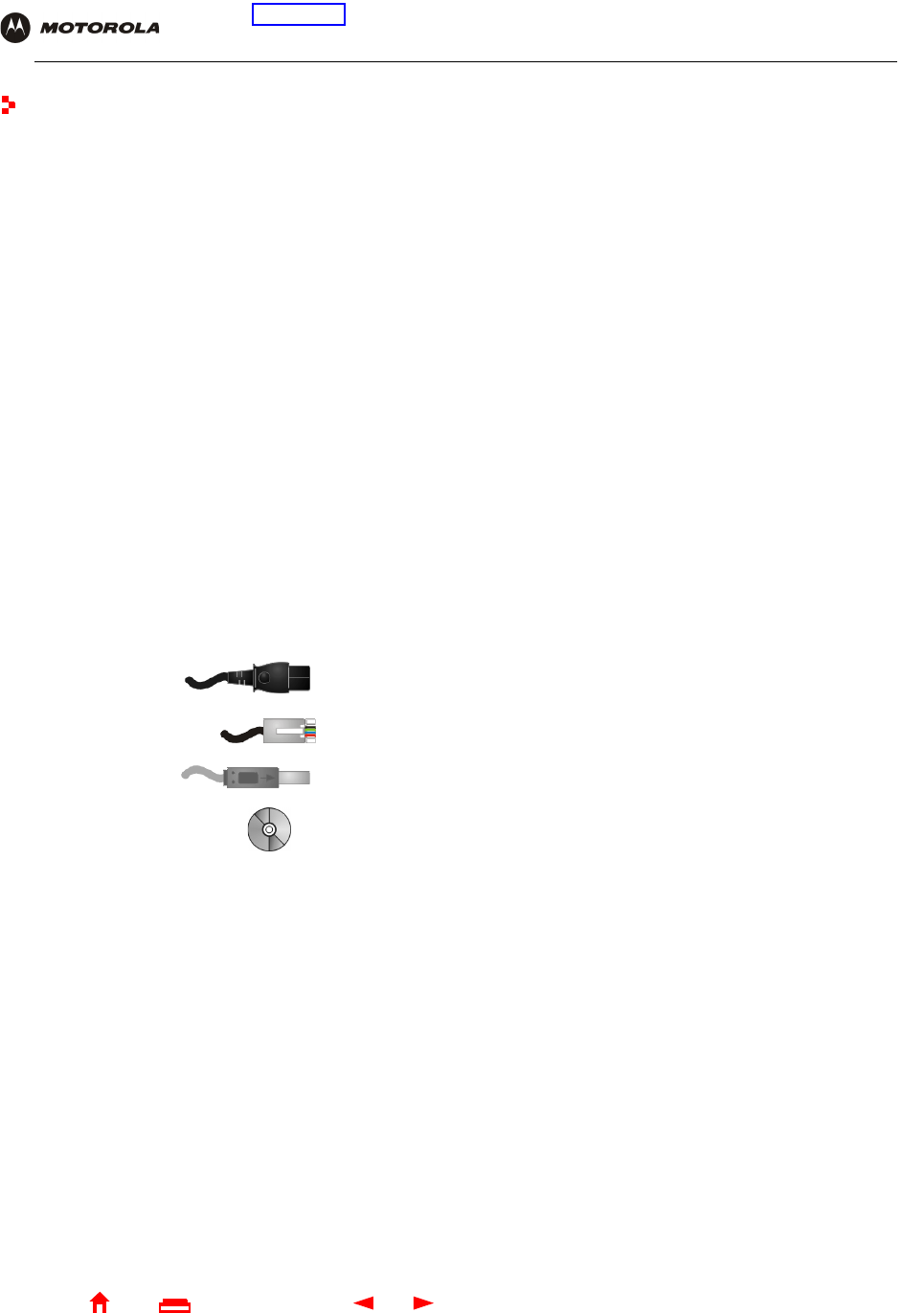
Before you begin the installation, check that you received the following items with your SBG940:
You will need 75-ohm coaxial cable with F-type connectors to connect the SBG940 to the nearest cable outlet. If a
TV is connected to the cable outlet, you may need a 5 to 900 MHz RF splitter and two additional coaxial cables to
use both the TV and the SBG940.
Determine the connection types you will make to the SBG940. Check that you have the required cables, adapters,
and adapter software. You may need:
Coaxial cable, RF splitters, hubs, and switches are available at consumer electronic stores.
Item Description
Power cord Connects the SBG940 to the AC electrical outlet
10/100Base-T
Ethernet cable
Connects to the Ethernet port
USB cable Connects to the USB port
SBG940 Installation
CD-ROM
Contains this User Guide and USB drivers
Wireless LAN Wireless adapter and driver software for each computer having a wireless connection (see “Optional
Accessories”)
Wired Ethernet
LAN
Ethernet cables and network interface cards (NICs) with accompanying installation software
To connect more than four computers to the SBG940, one or more Ethernet hubs or switches
USB A USB cable and the SBG940 Installation CD-ROM containing the software for USB installation
16 SBG940 User Guide
Home
X
ExitPrint
Overview Installation Troubleshooting Contact FAQ Specifications Glossary License
Configuration: Basic Gateway TCP/IP Wireless USB
Precautions
Postpone SBG940 installation until there is no risk of thunderstorm or lightning activity in the area.
To avoid potential shock, always unplug the power cord from the wall outlet or other power source before
disconnecting it from the SBG940 rear panel.
To prevent overheating the SBG940, do not block the ventilation holes on the sides of the unit.
Do not open the unit. Refer all service to your cable provider.
Wipe the unit with a clean, dry cloth. Never use cleaning fluid or similar chemicals. Do not spray cleaners directly
on the unit or use forced air to remove dust.
Signing Up for Service
You must sign up with a cable provider to access the Internet and other online services.
To activate your service, call your local cable provider.
You need to provide the MAC address marked HFC MAC ID printed on the Label on the Bottom of the SBG940.
You can record it in the SBG940 Quick Installation Guide.
You should ask your cable provider the following questions:
•Do you have any special system requirements?
•When can I begin to use my SBG940?
•Are there any files I need to download after I am connected?
•Do I need a user name or password to access the Internet or use e-mail?
To avoid damaging the SBG940 or computers with static electricity:
Always make the wall connection first.
Before you connect or disconnect the USB or
Ethernet cables, always touch the coaxial cable
connector on the SBG940.

17 SBG940 User Guide
Home
X
ExitPrint
Overview Installation Troubleshooting Contact FAQ Specifications Glossary License
Configuration: Basic Gateway TCP/IP Wireless USB
Computer System Requirements
You can connect Microsoft Windows, Macintosh, UNIX®, or Linux® computers equipped as follows to the
SBG940 LAN:
•One of the following:
•PC with Pentium class or better processor
•Windows® 98, Windows® 98 SE, Windows Me®, Windows® 2000, Windows XPTM, Windows NT®, Macintosh,
or Linux operating system with operating system CD-ROM available
•Minimum 16 MB RAM recommended
•10 MB available hard disk space
You can use any web browser such as Microsoft® Internet Explorer or Netscape Navigator® with the SBG940.
You can use the USB connection with any PC running Windows 98, Windows 2000, Windows Me, or Windows XP
that has a USB interface. The USB connection requires special USB driver software that is supplied on the
SBG940 Installation CD-ROM. You can upgrade your USB drivers from the Motorola Downloads page
http://broadband.motorola.com/noflash/usb_drivers.asp.
Ethernet 10Base-T or 10/100Base-T Ethernet adapter with proper NIC driver software installed.
Wireless Any IEEE 802.11g or IEEE 802.11b device. For information about the Motorola WN825G
Wireless Card (PCMCIA type II 3.3 V slot) or WPCI810G Wireless Adapter, see “Optional
Accessories”.
18 SBG940 User Guide
Home
X
ExitPrint
Overview Installation Troubleshooting Contact FAQ Specifications Glossary License
Configuration: Basic Gateway TCP/IP Wireless USB
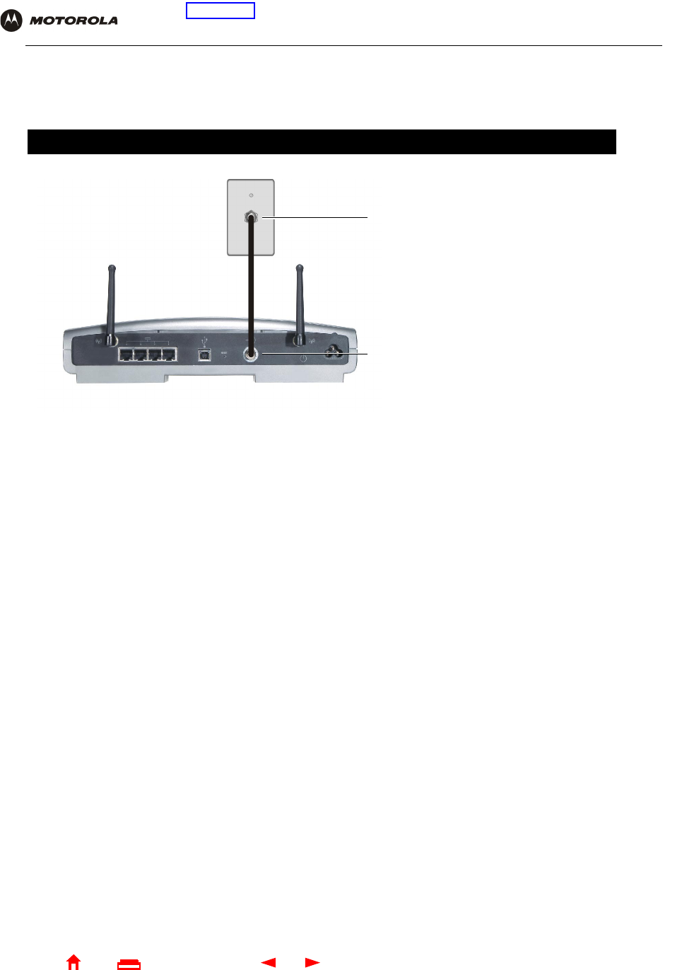
Connecting the SBG940 to the Cable System
1Be sure the computer is on and the SBG940 is unplugged.
2Connect one end of the coaxial cable to the cable outlet or splitter.
3Connect the other end of the coaxial cable to the cable connector on the SBG940.
Hand-tighten the connectors to avoid damaging them.
4Insert the SBG940 Installation CD-ROM into the CD-ROM drive.
5Plug the power cord into the power connector on the SBG940.
6Plug the power cord into the electrical outlet. This turns the SBG940 on. You do not need to unplug it when
not in use. The first time you plug in the SBG940, allow 5 to 30 minutes to find and lock on the appropriate
communications channels.
7Check that the lights on the front panel cycle through this sequence:
Cabling the LAN
After connecting to the cable system, you can connect your wired Ethernet LAN. Some samples are shown in
“Wired Ethernet LAN”. On each networked computer, you must install proper drivers for the Ethernet NIC. Detailed
information about network cabling is beyond the scope of this document.
Turns on when AC power is connected to the SBG940. Indicates that the power is connected properly.
DS Flashes while scanning for the downstream receive channel. Changes to solid green when the receive
channel is locked.
US Flashes while scanning for the upstream send channel. Changes to solid green when the send
channel is locked.
ONLINE Flashes during SBG940 registration and configuration. Changes to solid green when the SBG940
is registered.
Flashes when the SBG940 is transmitting or receiving data over the Internet.
Step 2
Step 3
To A C po we r
(steps 5 to 6)
19 SBG940 User Guide
Home
X
ExitPrint
Overview Installation Troubleshooting Contact FAQ Specifications Glossary License
Configuration: Basic Gateway TCP/IP Wireless USB
Obtaining an IP Address for Ethernet
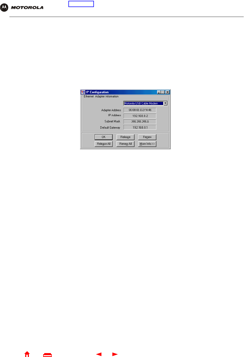
Obtaining an IP Address in Windows 98, Windows 98 SE, or Windows Me
You must do the following on each Ethernet client PC running Windows 98, Windows 98 SE, or Windows Me:
1On the Windows Desktop, click Start.
2Select Run. The Run window is displayed.
3Type winipcfg.exe and click OK. The IP Configuration window is displayed:
4Click the Renew button to obtain an IP address for the PC from the DHCP server on the SBG940.
Obtaining an IP Address in Windows 2000 or Windows XP
You must do the following on each Ethernet client PC running Windows 2000 or Windows XP:
1On the Windows Desktop, click Start.
2Select Run. The Run window is displayed.
3Type cmd and click OK to display a command prompt window.
4Type ipconfig /renew and press ENTER to obtain an IP address for the PC from the DHCP server on the
SBG940.
5Type exit and press ENTER to return to Windows.
Obtaining an IP Address on Macintosh or UNIX Systems
Follow the instructions in your user manual.
20 SBG940 User Guide
Home
X
ExitPrint
Overview Installation Troubleshooting Contact FAQ Specifications Glossary License
Configuration: Basic Gateway TCP/IP Wireless USB
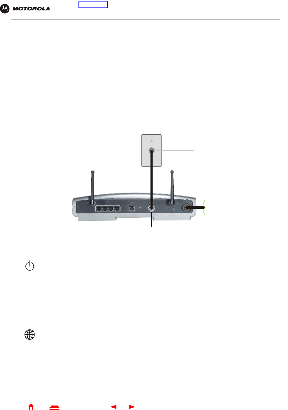
Connecting a PC to the USB Port
You can connect a single PC running Windows 98, Windows XP, Windows Me, or Windows 2000 to the SBG940
USB port.
To connect a PC to the USB port:
1Insert the SBG940 Installation CD-ROM in the CD-ROM drive.
2Install the USB driver following the appropriate procedure for “Setting Up a USB Driver”.
3Connect the USB cable to the USB port on the SBG940 Rear Panel.
4Connect the other end to the USB port on the computer.
Caution!
Before plugging in the USB cable, be sure the SBG940 Installation CD-ROM is inserted in the PC
CD-ROM drive.
Step 3
Step 4
To A C
power
Step 1
21 SBG940 User Guide
Home
X
ExitPrint
Overview Installation Troubleshooting Contact FAQ Specifications Glossary License
Configuration: Basic Gateway TCP/IP Wireless USB
Wall Mounting
If you mount the unit on the wall, you must:
•Locate the unit as specified by the local or national codes governing residential or business cable TV and
communications services.
•Follow all local standards for installing a network interface unit/network interface device (NIU/NID).
If possible, mount the unit to concrete, masonry, a wooden stud, or other very solid wall material. Use anchors if
necessary; for example, if you must mount the unit on drywall.
To mount your SBG940 on the wall:
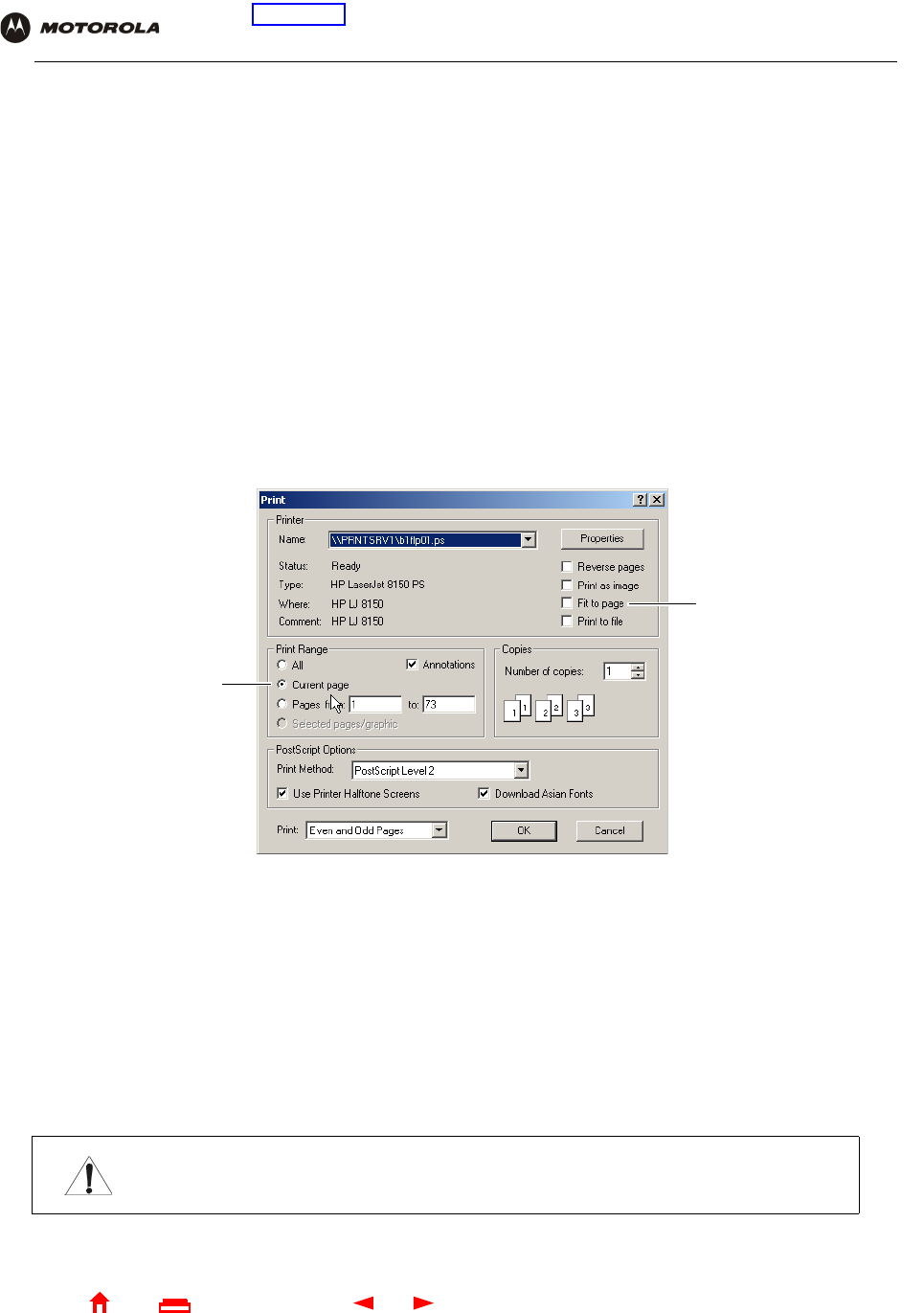
1Print the Wall Mounting Template on page 23.
Go to page 23 and click the Print icon or choose Print from the File menu to display the Print dialog box.
(The following image is from Adobe Acrobat Reader® version 4.0 running on Windows 2000; there may be
slight differences in your version.)
Be sure you print the template at 100% scale. Be sure Fit to page is not selected.
To print the template only, select Current page as the Print Range.
Click the OK button to print the template.
2Measure the printed template with a ruler to ensure that it is the correct size.
3Use a center punch to mark the center of the holes.
4On the wall, locate the marks for the mounting holes.
5Drill the holes to a depth of at least 11/2 inches (3.8 cm).
Caution!
Before drilling holes, check the structure for potential damage to water, gas, or electric lines.
Be sure this is
not selected.
Select this to print
page 23 only.
22 SBG940 User Guide
Home
X
ExitPrint
Overview Installation Troubleshooting Contact FAQ Specifications Glossary License
Configuration: Basic Gateway TCP/IP Wireless USB
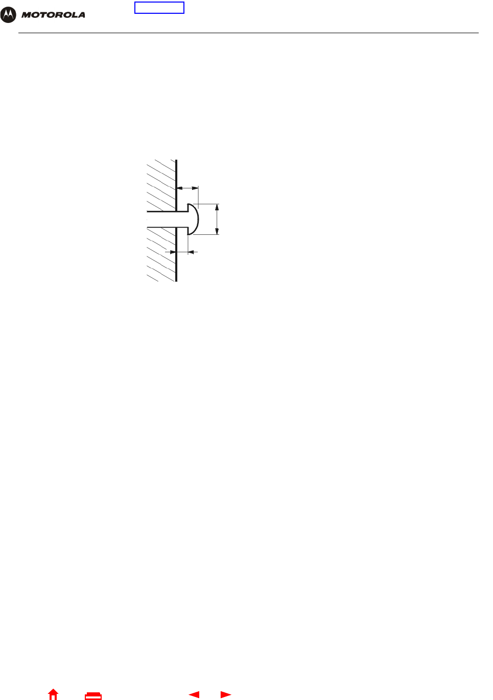
6If necessary, seat an anchor in each hole.
Use M5 x 38 mm (#10-16 x 11/2 inch) screws with a flat underside and maximum screw head diameter of
10.5 mm to mount the SBG940.
7Using a screwdriver, turn each screw until part of it protrudes from the wall, as shown:
•There must be .16 inches (4.0 mm) between the wall and the underside of the screw head.
•The maximum distance from the wall to the top of the screw head is 7.6 mm (.3 in).
8Place the SBG940 so the keyholes on the back of the unit are aligned above the mounting screws.
Be sure you do not damage the antennas.
9Slide the SBG940 down until it stops against the top of the keyhole opening.
.3 inches (7.6 mm) maximum
.4 inches (10.5 mm) maximum
.16 inches (4.0 mm)
23 SBG940 User Guide
Home
X
ExitPrint
Overview Installation Troubleshooting Contact FAQ Specifications Glossary License
Configuration: Basic Gateway TCP/IP Wireless USB
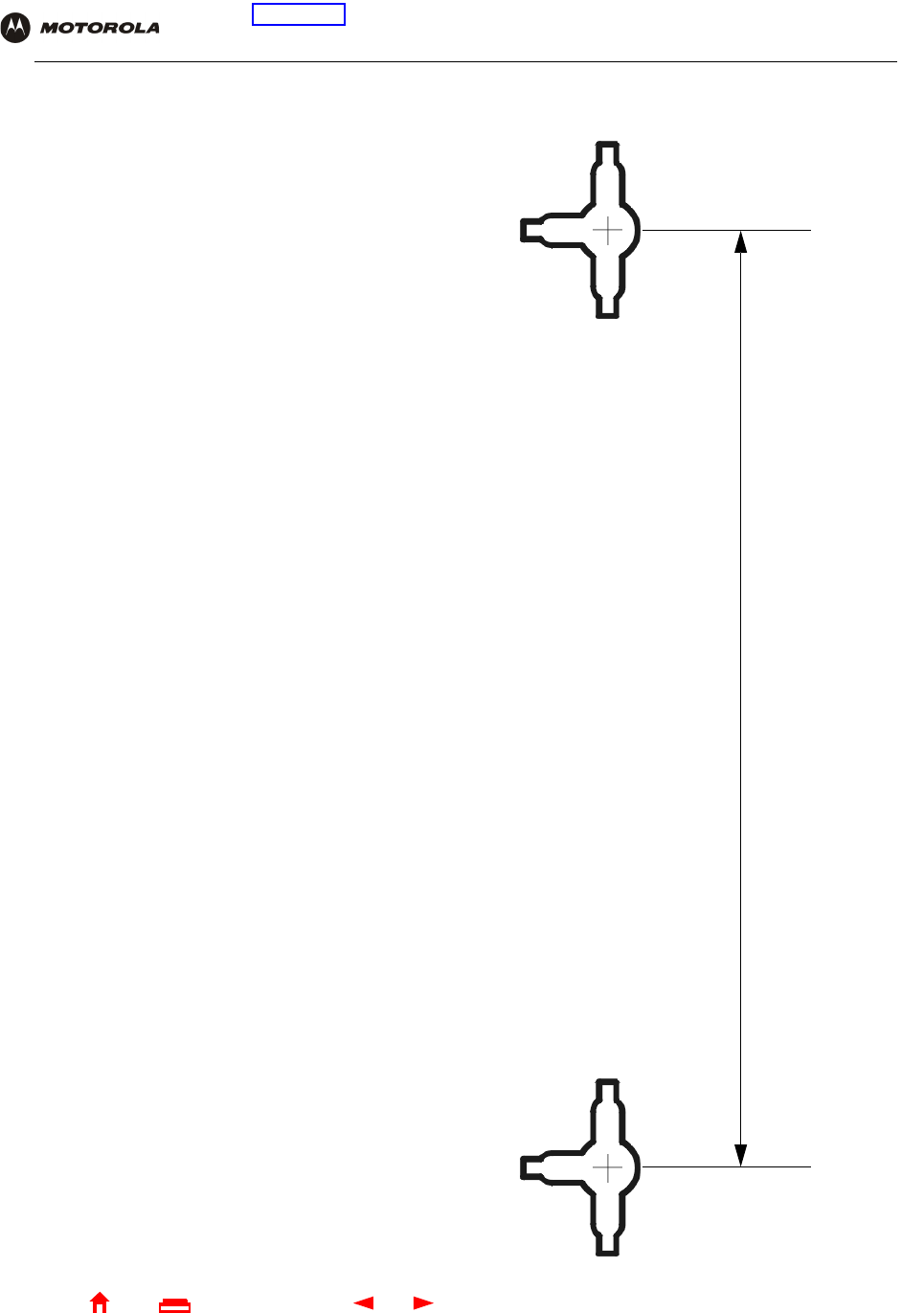
Wall Mounting Template
You can print this page to use as a wall mounting template.
Be sure you print it at 100% scale. In Acrobat Reader, be sure
that Fit To Page is not selected in the Print dialog box.
Measure the printed template with a ruler to ensure that it is
the correct size.
17.24 cm.
6.79 in.
24 SBG940 User Guide
Home
X
ExitPrint
Overview Installation Troubleshooting Contact FAQ Specifications Glossary License
Configuration: Basic Gateway TCP/IP Wireless USB
Basic Configuration
The following sections provide information about basic SBG940 configuration:
•Starting the SBG940 Setup Program
•Changing the Default Password
•Getting Help
•Setting the Firewall Policy
•Gaming Configuration Guidelines
For more advanced configuration information, see “Configuring TCP/IP”, “Setting Up Your Wireless LAN”, or
“Setting Up a USB Driver”.
For normal operation, you do not need to change most default settings. The following caution statements
summarize the issues you must be aware of:
Caution!
To prevent unauthorized configuration, change the default password immediately when you first
configure the SBG940. See “Changing the Default Password”.
Firewalls are not foolproof. Choose the most secure firewall policy you can. See “Setting the
Firewall Policy”.
If you are using a wired LAN only and have no wireless clients, be sure you disable the wireless
interface by turning off Enable Wireless Interface on the Wireless > NETWORK Page.
For a wireless LAN only, be sure you follow the instructions in “Setting Up Your Wireless LAN”.
25 SBG940 User Guide
Home
X
ExitPrint
Overview Installation Troubleshooting Contact FAQ Specifications Glossary License
Configuration: Basic Gateway TCP/IP Wireless USB
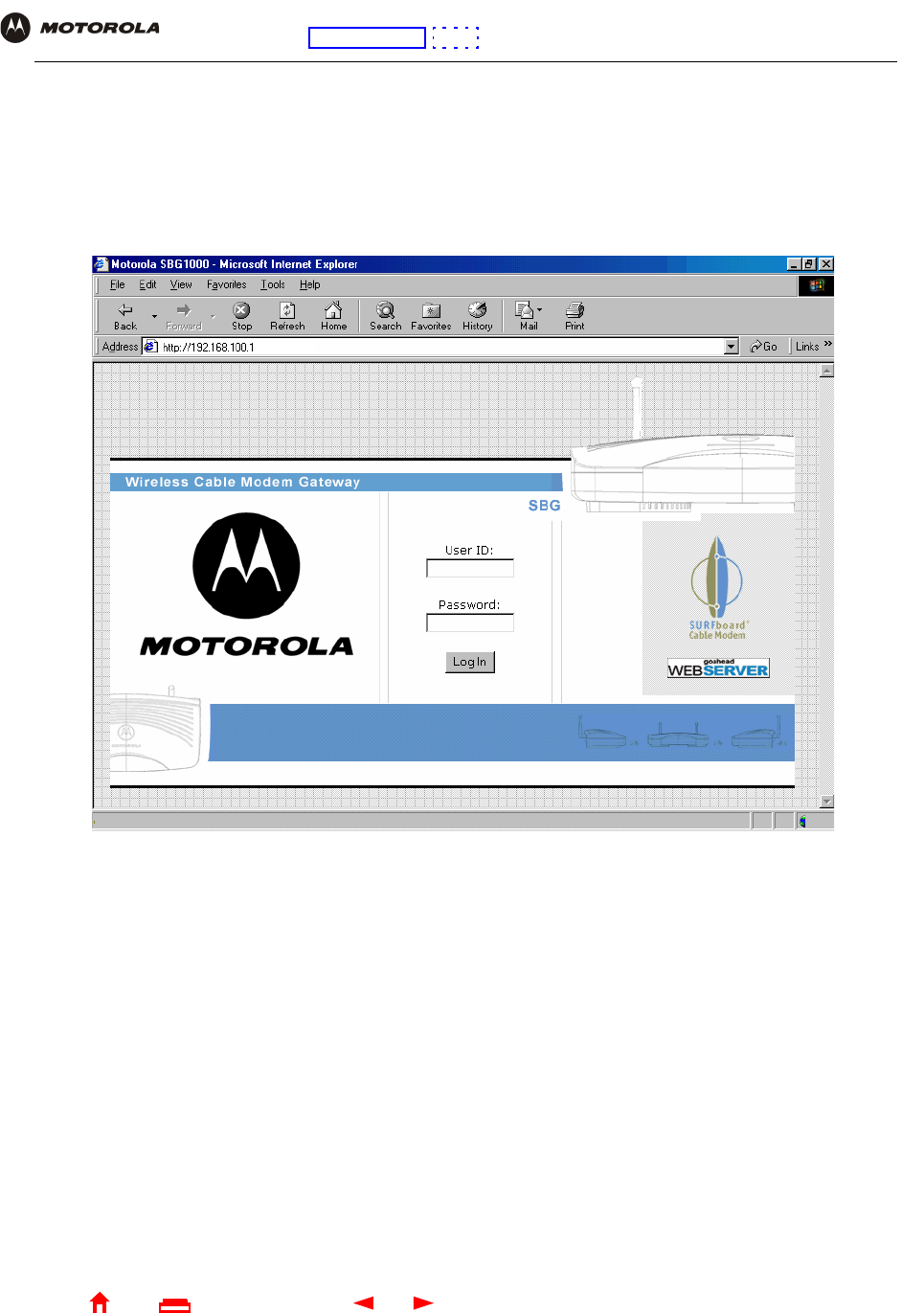
Starting the SBG940 Setup Program
1On a computer wired to the SBG940 over Ethernet or USB, open a web browser. Do not attempt to configure
the SBG940 over a wireless connection.
2In the Address or Location field, type http://192.168.100.1 or http://192.168.0.1 and press ENTER to display
the Log In window:
3In the User ID field, type the User Name; the default is “admin” (this field is case sensitive).
4In the Password field, type the Password; the default is “motorola” (this field is case sensitive).
26 SBG940 User Guide
Home
X
ExitPrint
Overview Installation Troubleshooting Contact FAQ Specifications Glossary License
Configuration: Basic Gateway TCP/IP Wireless USB
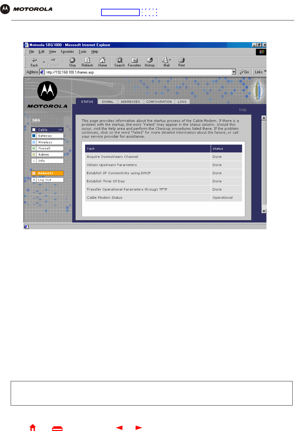
5Click Log In to display the SBG940 user configuration and status windows:
If you have difficulty starting the SBG940 Setup Program, see “Troubleshooting” for information.
Router is a configuration option that may appear on your window but may not be supported.
Click To Perform
Cable Configure and monitor the cable system connection.
Gateway Configure and monitor the gateway preferences (see Configuring the Gateway).
Wireless Configure and monitor the wireless interface (see “Setting Up Your Wireless LAN”).
Firewall Configure and monitor the firewall (see “Setting the Firewall Policy”).
Admin Changing the Default Password.
Info Display information about the SBG940 Setup Program.
Reboot Restart the SBG940. It is the same as pressing the reset button on the rear panel for less than five
seconds.
Log Out Log out of the SBG940.
For some settings, after you edit the field and click Apply, you are warned that you must reboot for your change
to take effect. Rebooting takes 10 to 15 seconds. After rebooting, you must log in again.
27 SBG940 User Guide
Home
X
ExitPrint
Overview Installation Troubleshooting Contact FAQ Specifications Glossary License
Configuration: Basic Gateway TCP/IP Wireless USB
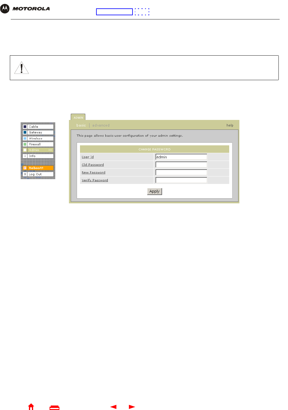
Changing the Default Password
To change the default password:
1On the SBG940 Setup Program left panel, click Admin to display the ADMIN — basic page:
2In the Old Password field, type the old password. The default password is “motorola” (this field is case
sensitive).
3In the New Password field, type the new password.
4In the Verify Password field, type the new password again.
5Click Apply to apply your changes.
Caution!
To prevent unauthorized configuration, change the default password immediately when you first
configure the Motorola SURFboard Wireless Cable Modem Gateway.
28 SBG940 User Guide
Home
X
ExitPrint
Overview Installation Troubleshooting Contact FAQ Specifications Glossary License
Configuration: Basic Gateway TCP/IP Wireless USB
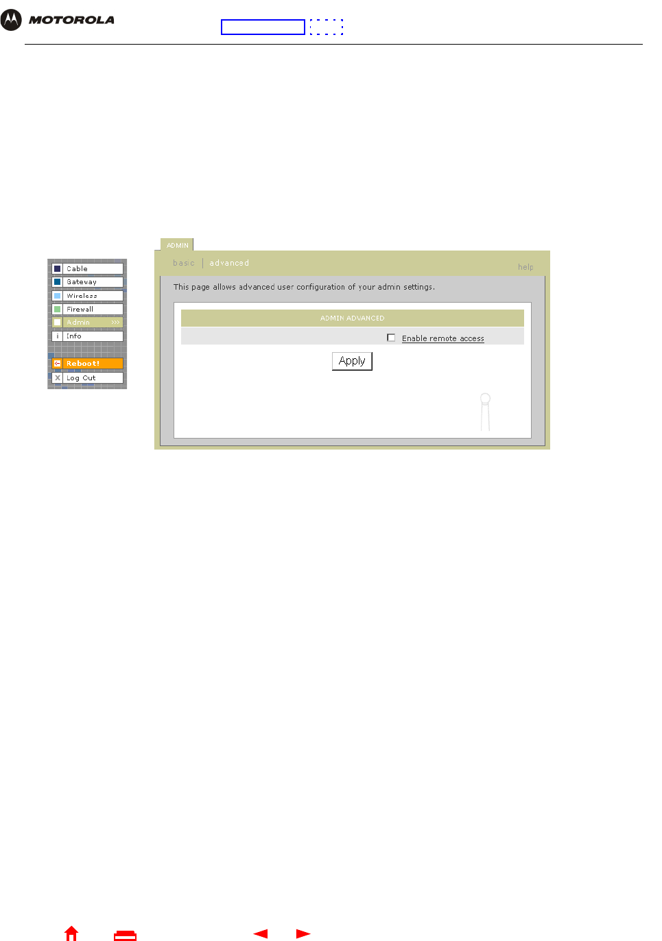
Enabling Remote Access
You can enable remote access to the SBG940 over the Internet. You must know the userid, password, and
public IP address assigned to your SBG940 to run the Setup Program over the Internet. Remote access is
provided using a web browser on the remote client and connecting to the SBG940 web server.
To enable remote access to the SBG940:
1On the SBG940 Setup Program left panel, click Admin to display the ADMIN — basic page.
2Click advanced to display the ADMIN — advanced page.
3Click the box next to Enable remote access to enable it.
4Click Apply to apply your change.
29 SBG940 User Guide
Home
X
ExitPrint
Overview Installation Troubleshooting Contact FAQ Specifications Glossary License
Configuration: Basic Gateway TCP/IP Wireless USB
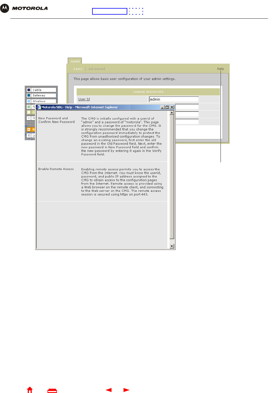
Getting Help
To get help on any underlined item or field, click the text. For example, if you click a field or the help button on the
ADMIN — basic page, the following help is displayed:
You can scroll to browse the help or click another item to display help for that item.
This button also displays
help for the window.
30 SBG940 User Guide
Home
X
ExitPrint
Overview Installation Troubleshooting Contact FAQ Specifications Glossary License
Configuration: Basic Gateway TCP/IP Wireless USB
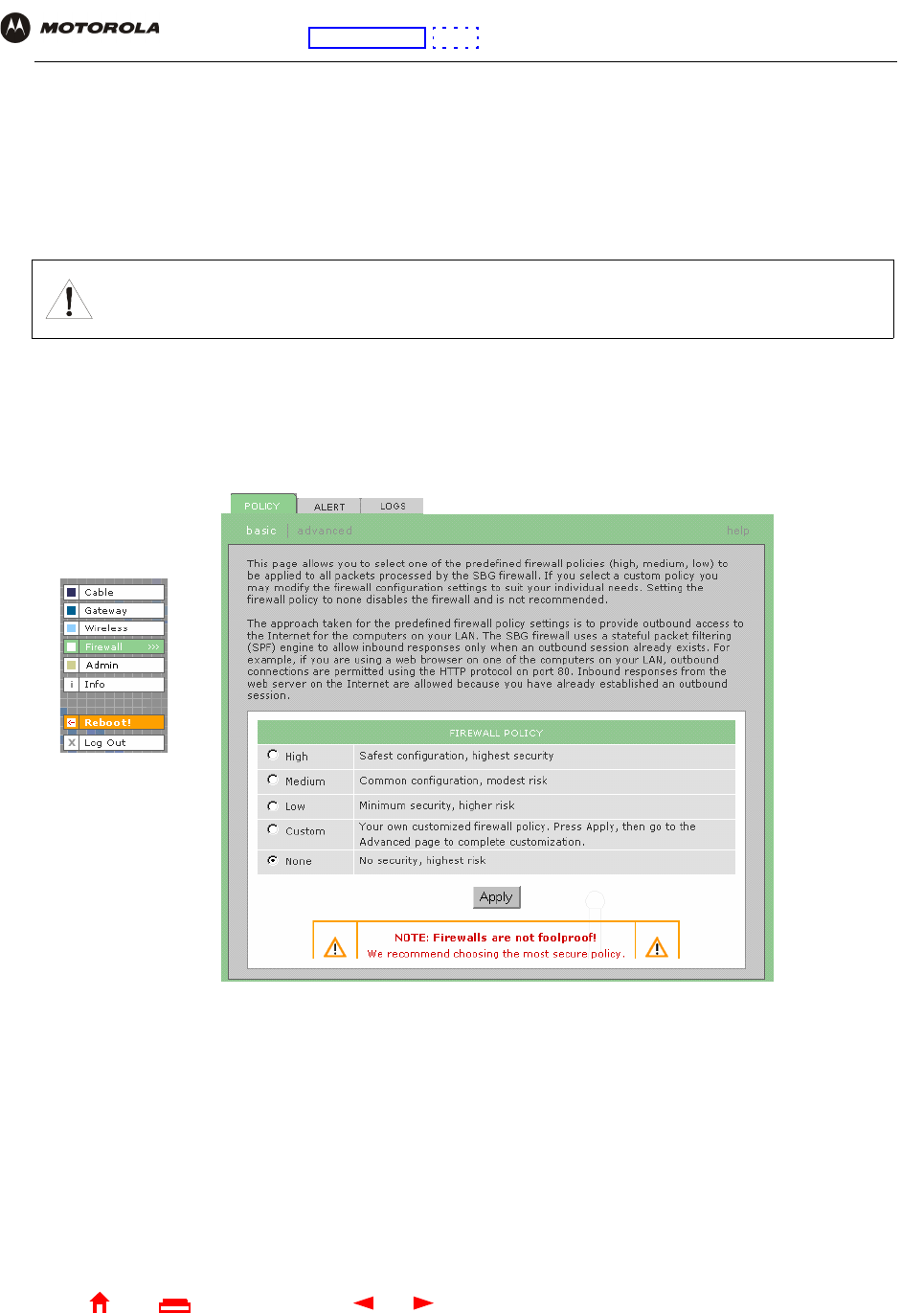
Setting the Firewall Policy
The SBG940 firewall protects the SBG940 LAN from undesired attacks and other intrusions from the Internet. This
section describes using the Firewall > POLICY — basic page to choose one of the predefined firewall policy
templates provided with the SBG940.
To select a predefined policy for all packets processed by the SBG940 firewall:
1On the SBG940 Setup Program left panel, click Firewall.
2Click POLICY.
3Click basic to display the predefined firewall policy templates:
4Select the most secure firewall policy you can:
Caution!
Firewalls are not foolproof. Choose the most secure firewall policy you can. To enable easy network
setup, the default firewall policy is None, which provides no security.
High The safest predefined firewall policy template, providing the highest security. We recommend this setting.
Medium A predefined firewall policy template providing a common configuration having modest risk.
Low A predefined firewall policy template providing minimum security, with a higher risk of intrusions.
Custom You may need to create a custom firewall policy on the Firewall > POLICY — advanced Page. Do not
create a custom policy unless you have the necessary expertise and the need to do so.
None Disables the firewall. To enable easy network setup, it is the default. After you set up your network, use
High, Medium, or Low to improve your security.
31 SBG940 User Guide
Home
X
ExitPrint
Overview Installation Troubleshooting Contact FAQ Specifications Glossary License
Configuration: Basic Gateway TCP/IP Wireless USB
5Click Apply to apply your changes.
If you have the need, you can:
•View the rules for the High, Medium, or Low predefined policy templates or create a custom policy on the
Firewall > POLICY — advanced Page
•Configure a firewall alert on Firewall > ALERT — basic Page and Firewall > ALERT — email Page
•View the firewall logs on the Firewall > LOGS Page
For information about how the firewall can affect gaming, see “Gaming Configuration Guidelines”.
The predefined policies provide outbound Internet access for computers on the SBG940 LAN. The SBG940
firewall uses stateful inspection to allow inbound responses when there already is an outbound session running
corresponding to the data flow. For example, if you use a web browser, outbound HTTP connections are permitted
on port 80. Inbound responses from the Internet are allowed because an outbound session is established.
When required, you can configure the SBG940 firewall to allow inbound packets without first establishing an
outbound session. You also need to configure a port forwarding entry on the
Gateway > PORT FORWARDING — config Page or a DMZ client on the Gateway > LAN — nat config Page.
After you edit some fields and click Apply, you are warned that you must reboot for your change to take effect.
Rebooting takes 10 to 15 seconds. After rebooting, you must log in again.
32 SBG940 User Guide
Home
X
ExitPrint
Overview Installation Troubleshooting Contact FAQ Specifications Glossary License
Configuration: Basic Gateway TCP/IP Wireless USB
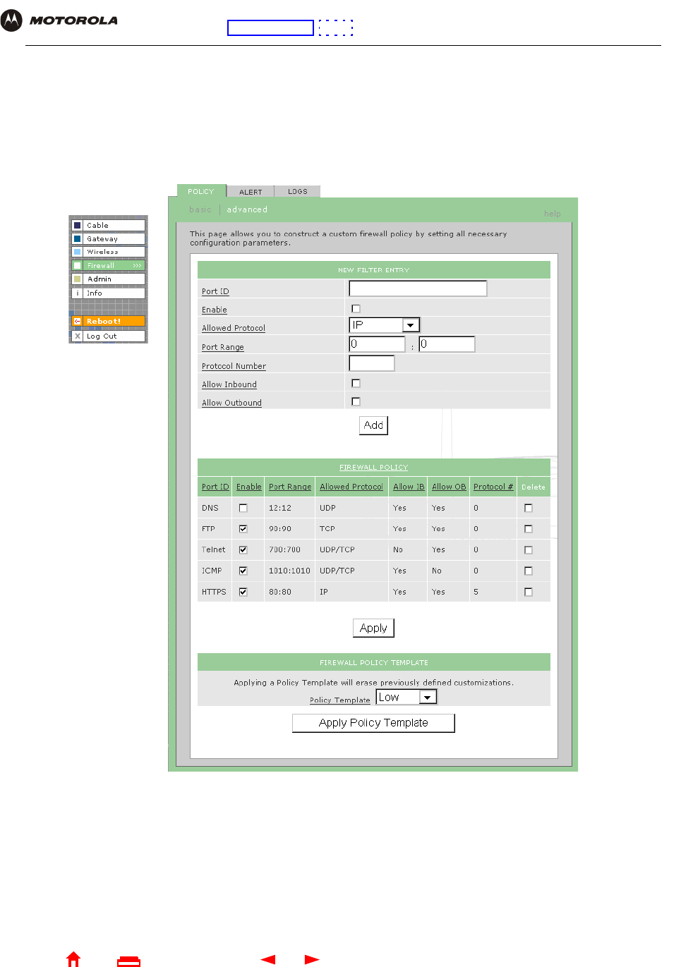
Firewall > POLICY — advanced Page
Do not create a custom firewall policy unless you have the necessary expertise and the need to do so. Instead,
select one of the predefined policy templates as described in “Setting the Firewall Policy”.
To create a custom firewall policy, first select Custom and click Apply on the Firewall > POLICY — basic Page.
Then use this page to configure a custom firewall policy:
To base the custom policy on a predefined firewall policy template, choose High, Medium, or Low in the Policy
Template field and click Apply Policy Template.

33 SBG940 User Guide
Home
X
ExitPrint
Overview Installation Troubleshooting Contact FAQ Specifications Glossary License
Configuration: Basic Gateway TCP/IP Wireless USB
.
Firewall > POLICY — advanced page fields
Field Description
NEW FILTER ENTRY Use these fields to set up one or more custom firewall filters, if you have the necessary
expertise.
Port ID Type the protocol being filtered.
Enable Select this box to enable firewall policy filtering for the port.
Allowed Protocol Select the allowed protocols from the drop-down list.
Port Range (From:To) Sets the port range, which must contain all ports required by the protocol.
Protocol Number Sets the protocol number of the IP packets to allow.
Allow Inbound Enables you to specify the port(s) on which inbound packets can pass through the firewall
from the Internet to your LAN.
Allow Outbound Enables you to specify the port(s) on which outbound packets can pass through the
firewall from your LAN to the Internet. Stateful inspection ensures appropriate responses
for outbound sessions.
Add Click to add the new filter. It is displayed on the FIREWALL POLICY table.
FIREWALL POLICY Table Lists your custom firewall filters.
Enable Select this box to enable firewall policy filtering for the port.
Delete Select the Delete box to delete the filter.
Apply Click to apply your changes.
FIREWALL POLICY
TEMPLATE
Policy Template You can use this drop-down list to select a predefined policy template on which to base
your custom template — High, Medium, or Low. These templates are described in “Setting
the Firewall Policy”
Apply Policy Template Click to apply the selected Policy Template and cancel any customizations.
34 SBG940 User Guide
Home
X
ExitPrint
Overview Installation Troubleshooting Contact FAQ Specifications Glossary License
Configuration: Basic Gateway TCP/IP Wireless USB
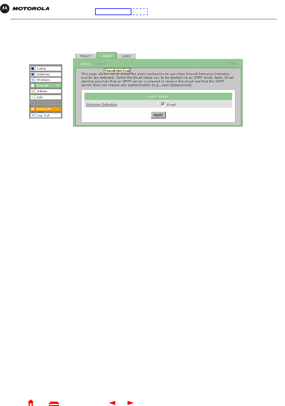
Firewall > ALERT — basic Page
You can use this page to set the alert mechanism for firewall intrusion detection events.
Firewall > ALERT — basic page fields
Field or Button Description
Intrusion Detection Select Email to be alerted through SMTP e-mail. An SMTP server that does not require any
authentication such as a user name or password must be present to receive the e-mail.
Apply Click to apply your changes.
35 SBG940 User Guide
Home
X
ExitPrint
Overview Installation Troubleshooting Contact FAQ Specifications Glossary License
Configuration: Basic Gateway TCP/IP Wireless USB
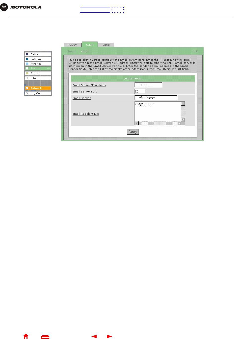
Firewall > ALERT — email Page
You can use this page to configure the e-mail alert parameters:
Firewall > ALERT — email page fields
Field or Button Description
E-mail Server IP Address Sets the e-mail server IP address in dotted-decimal format.
E-mail Server Port Sets the e-mail server port number.
E-mail Sender Sets the sender e-mail address.
E-mail Recipient List Sets the list of e-mail addresses that receive alerts from the SBG940 firewall.
Apply Click to apply your changes.
36 SBG940 User Guide
Home
X
ExitPrint
Overview Installation Troubleshooting Contact FAQ Specifications Glossary License
Configuration: Basic Gateway TCP/IP Wireless USB
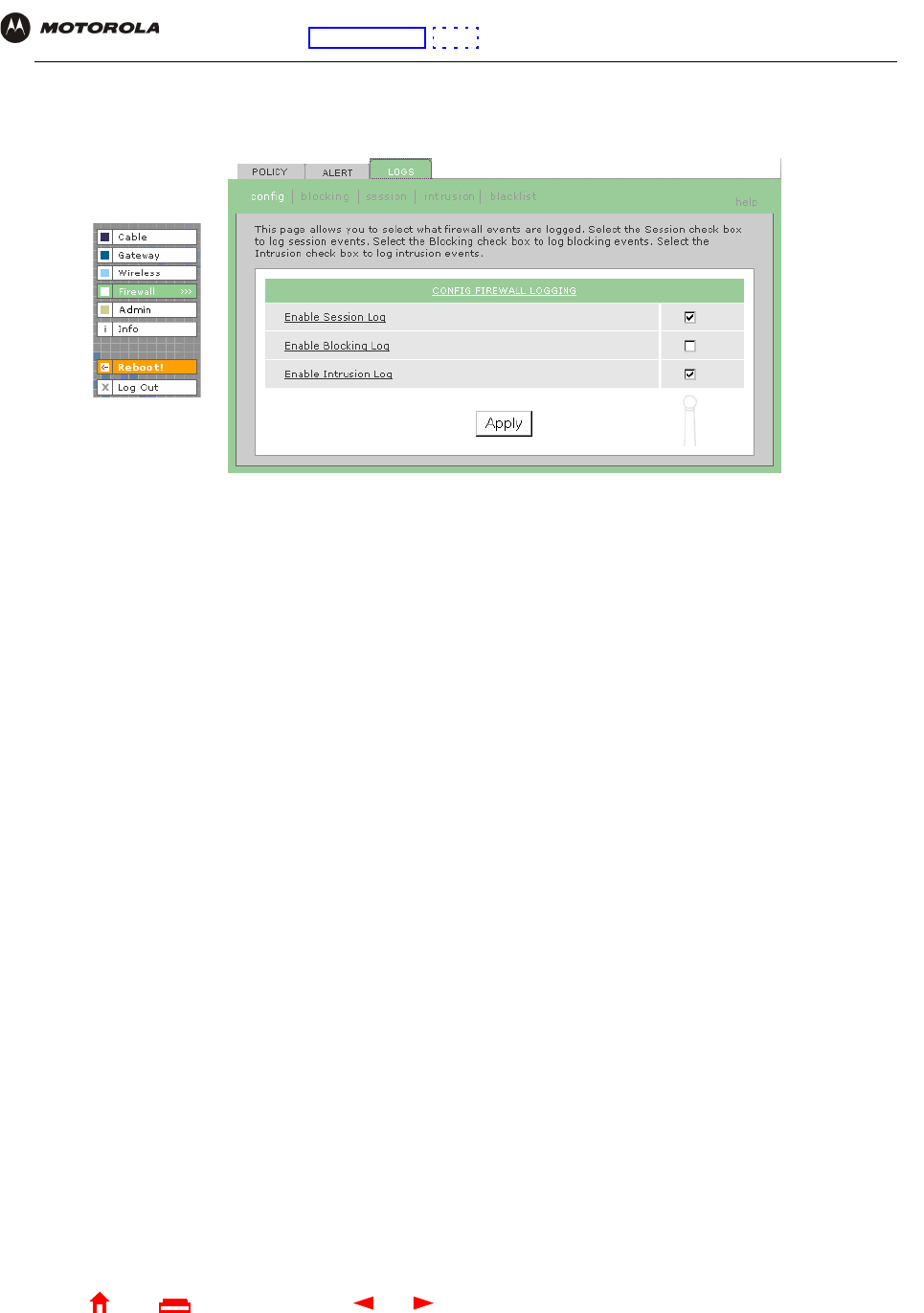
Firewall > LOGS Page
You can use this page to set which firewall events are logged.
If you enable the firewall, the blacklist log is always generated. Any IP address the firewall determines to have
breached the active policy is added to the blacklist log. To view the blacklist log, click blacklist. The firewall blocks
all traffic to and from a blacklisted IP address for 24 hours or until you reboot the SBG940 or manually clear the
blacklist by clicking Clear on the Firewall > LOGS — blacklist page.
Firewall > LOGS page fields
Field or Button Description
Enable Session Log Select this box to log every data session from the private LAN that was authorized by the
SBG940 firewall. Usually, the session log displays a history of normal data traffic. It also lists
the start of sessions the firewall terminated because:
•The policy was changed
•They were eventually determined to be an intrusion or attack
To display the session log, click session.
Enable Blocking Log Select this box to log inbound and outbound packets that the SBG940 firewall:
•Does not allow to pass because they use protocols and/or ports not explicitly allowed by
the active policy
•Determines to be invalid because of a session or reassembly timeout
To display the blocking log, click blocking.
Enable Intrusion Log Select this box to log attacks using common network intrusion tactics that the SBG940 firewall
detects and stops.
To display the intrusion log, click intrusion.
Apply Click to apply your changes.

37 SBG940 User Guide
Home
X
ExitPrint
Overview Installation Troubleshooting Contact FAQ Specifications Glossary License
Configuration: Basic Gateway TCP/IP Wireless USB
Gaming Configuration Guidelines
The following subsections provide information about configuring the SBG940 firewall and DMZ for gaming.
Configuring the Firewall for Gaming
By default, the SBG940 firewall is disabled. If, as recommended, you enable the firewall, refer to the game’s
documentation to ensure that the necessary ports are open for use by that game.
The pre-defined SBG940 firewall policies affect Xbox LiveTM as follows:
Configuring Port Triggers
Because the SBG940 has pre-defined port triggers for games using any of the following applications, no user
action is required to enable them:
•DirectX 7 and DirectX 8
•MSN Games by Zone.com
•Battle.net®
For a list of games supported by Battle.net, visit http://www.battle.net.
You may need to create custom port triggers to enable other games to operate properly. If you set custom port
triggers and enable the firewall, you must customize the firewall to allow traffic through those ports. To create
custom port triggers, use the Gateway > PORT TRIGGERS — custom Page.
Low Xbox Live data can pass through the firewall. No user action is required.
Medium or high To enable Xbox Live traffic to pass, you must configure:
•Choose Custom on the Firewall > POLICY — basic Page
•UDP 88:88 and UDP/TCP 3074:3074 on the Firewall > POLICY — advanced Page
38 SBG940 User Guide
Home
X
ExitPrint
Overview Installation Troubleshooting Contact FAQ Specifications Glossary License
Configuration: Basic Gateway TCP/IP Wireless USB
Configuring a Gaming DMZ Host
Some games and game devices require one of:
•The use of random ports
•The forwarding of unsolicited traffic
For example, to connect a PlayStation® 2 for PS2® online gaming, designate it as the gaming DMZ host because
the ports required vary from game to game. For these games, we recommend configuring the gaming computer or
device as a gaming DMZ device.
To configure a gaming DMZ device, on the Gateway > LAN — dhcp leases Page:
1Reserve a private IP address for the computer or game device MAC address.
2Designate the device as a DMZ device.
You can reserve IP addresses for multiple devices, but only one can be designated as the gaming DMZ at once.
Caution!
The gaming DMZ host is not protected by the firewall. It is open to communication or hacking from any
computer on the Internet. Consider carefully before configuring a device to be in the DMZ.
39 SBG940 User Guide
Home
X
ExitPrint
Overview Installation Troubleshooting Contact FAQ Specifications Glossary License
Configuration: Basic Gateway TCP/IP Wireless USB
Configuring the Gateway
This section describes the Gateway configuration pages in the SBG940 Setup Program:
•Gateway > STATUS Page
•Gateway > WAN Page
•Gateway > LAN — nat config Page
•Gateway > LAN — dhcp server config Page
•Gateway > LAN — dhcp leases Page
•Gateway > PORT FORWARDING — status Page
•Gateway > PORT FORWARDING — config Page
•Gateway > PORT TRIGGERS — predefined Page
•Gateway > PORT TRIGGERS — custom Page
•Gateway > LOG Page
After you edit some fields and click Apply, you are warned that you must reboot for your change to take effect.
Rebooting takes 10 to 15 seconds. After rebooting, you must log in again.
40 SBG940 User Guide
Home
X
ExitPrint
Overview Installation Troubleshooting Contact FAQ Specifications Glossary License
Configuration: Basic Gateway TCP/IP Wireless USB
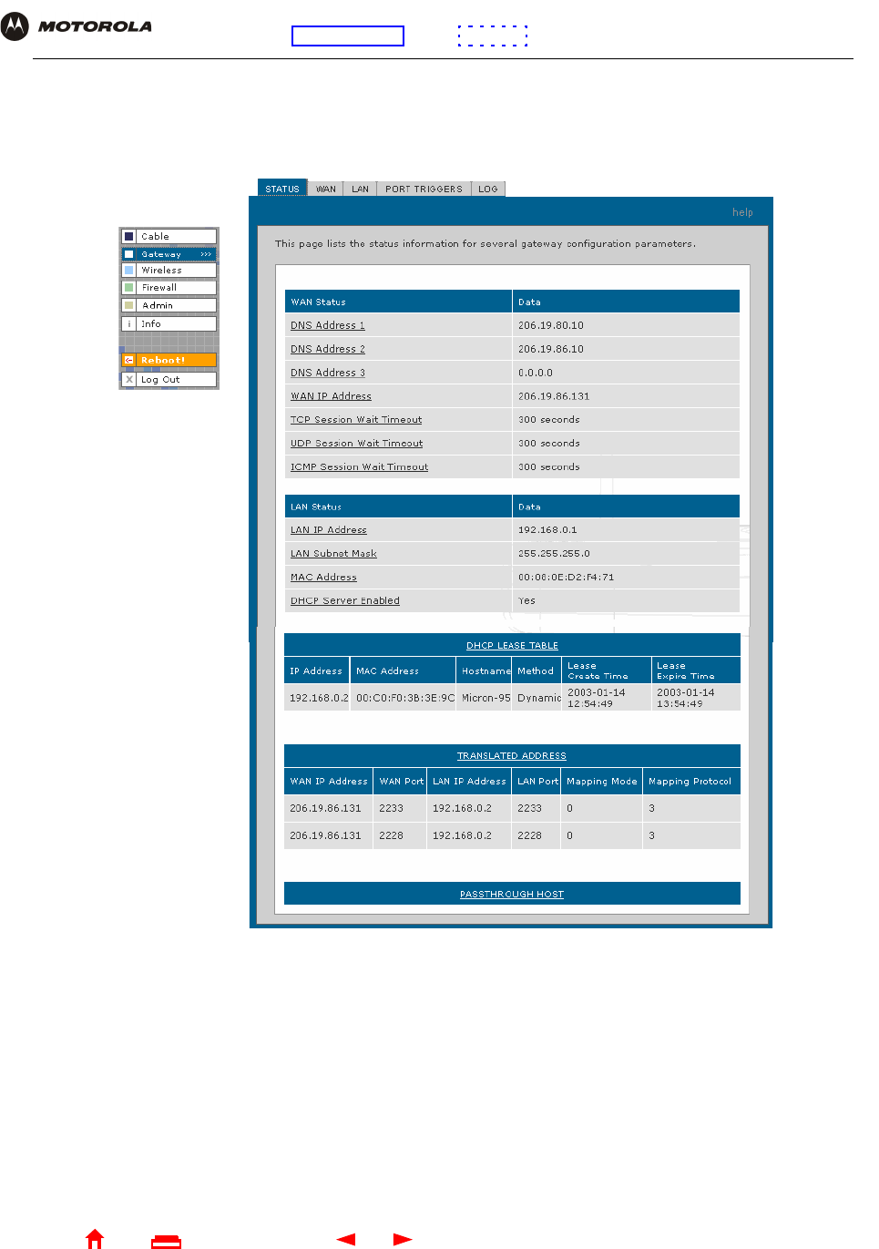
Gateway > STATUS Page
This page displays the gateway status information:
These fields display settings that are set on the other Gateway pages. For field descriptions, see the following
subsections that describe the fields on each tab.
41 SBG940 User Guide
Home
X
ExitPrint
Overview Installation Troubleshooting Contact FAQ Specifications Glossary License
Configuration: Basic Gateway TCP/IP Wireless USB
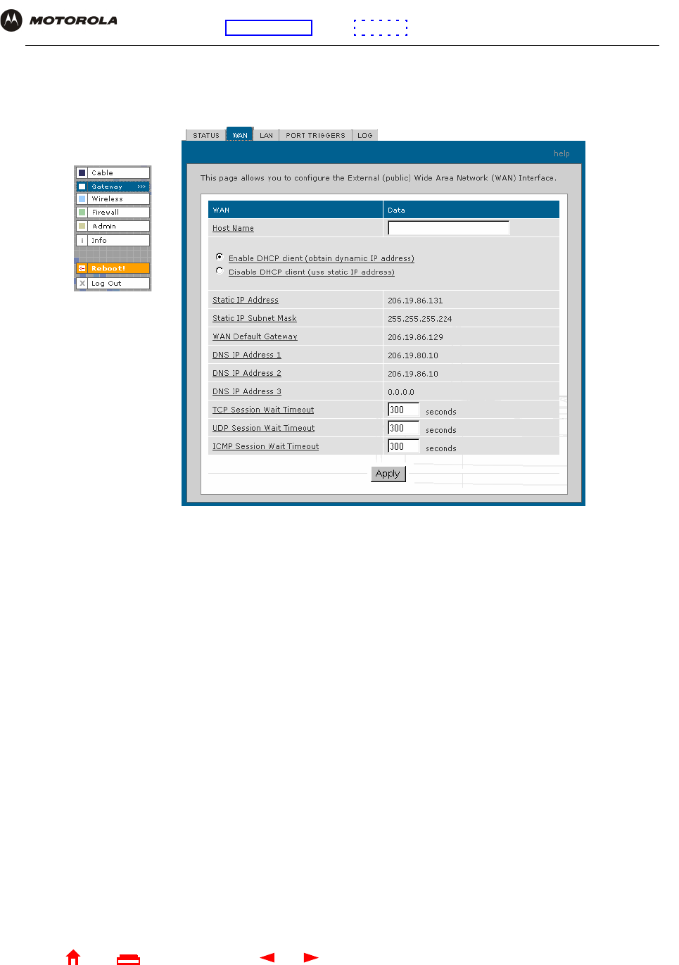
Gateway > WAN Page
Use this page to configure the external (public) wide area network (WAN) interface:
Gateway > WAN page fields
Field Description
Host Name If the cable provider requires a hostname to access to their network, type the hostname
they provided in this field. The default is None.
Enable DHCP Client
(obtain dynamic IP
address)
Enabling the DHCP client causes the wireless gateway to automatically obtain the public
IP address, subnet mask, domain name, and DNS server(s). Most commonly, the DHCP
client is enabled if the cable provider automatically assigns a public IP address from their
DHCP server. Enable DHCP Client is selected by default.
Disable DHCP Client (use
static IP address)
If the cable provider does not automatically assign a public IP address using DHCP, they
must provide a static IP address. Select Disable DHCP Client. When you disable the
DHCP client, you must type the static IP address, subnet mask, DNS server(s), and
domain name (if necessary) in the fields provided. Disable DHCP Client is not selected
by default.
Static IP Address If Disable DHCP Client is selected, type the static IP address provided by the cable
provider in dotted-decimal format. The default is None.
Static IP Subnet Mask If Disable DHCP Client is selected, type the subnet mask associated with the static IP
address in dotted-decimal format. The default is None.
WAN Default Gateway When using a Static IP Address from the cable provider, type the default gateway IP
address on the WAN for the SBG940 in dotted-decimal format.

42 SBG940 User Guide
Home
X
ExitPrint
Overview Installation Troubleshooting Contact FAQ Specifications Glossary License
Configuration: Basic Gateway TCP/IP Wireless USB
DNS IP Address 1
DNS IP Address 2
DNS IP Address 3
The cable provider DNS server provides name-to-IP address resolution. If the cable
provider does not automatically assign DNS addresses from their DHCP server, they must
provide at least one DNS server IP address to enter in these fields in dotted-decimal
format. The default is None.
TCP Session Wait
Timeout
Sets the maximum time in seconds to wait before assuming a TCP session has timed out.
The default is 24 hours.
UDP Session Wait
Timeout
Sets the maximum time in seconds to wait before assuming a UDP session has timed out.
The default is 300 seconds (5 minutes).
ICMP Session Wait
Timeout
Sets the maximum time in seconds to wait before assuming an ICMP session has timed
out. The default is 300 seconds (5 minutes).
Apply Click to apply your changes.
Gateway > WAN page fields (continued)
Field Description
43 SBG940 User Guide
Home
X
ExitPrint
Overview Installation Troubleshooting Contact FAQ Specifications Glossary License
Configuration: Basic Gateway TCP/IP Wireless USB
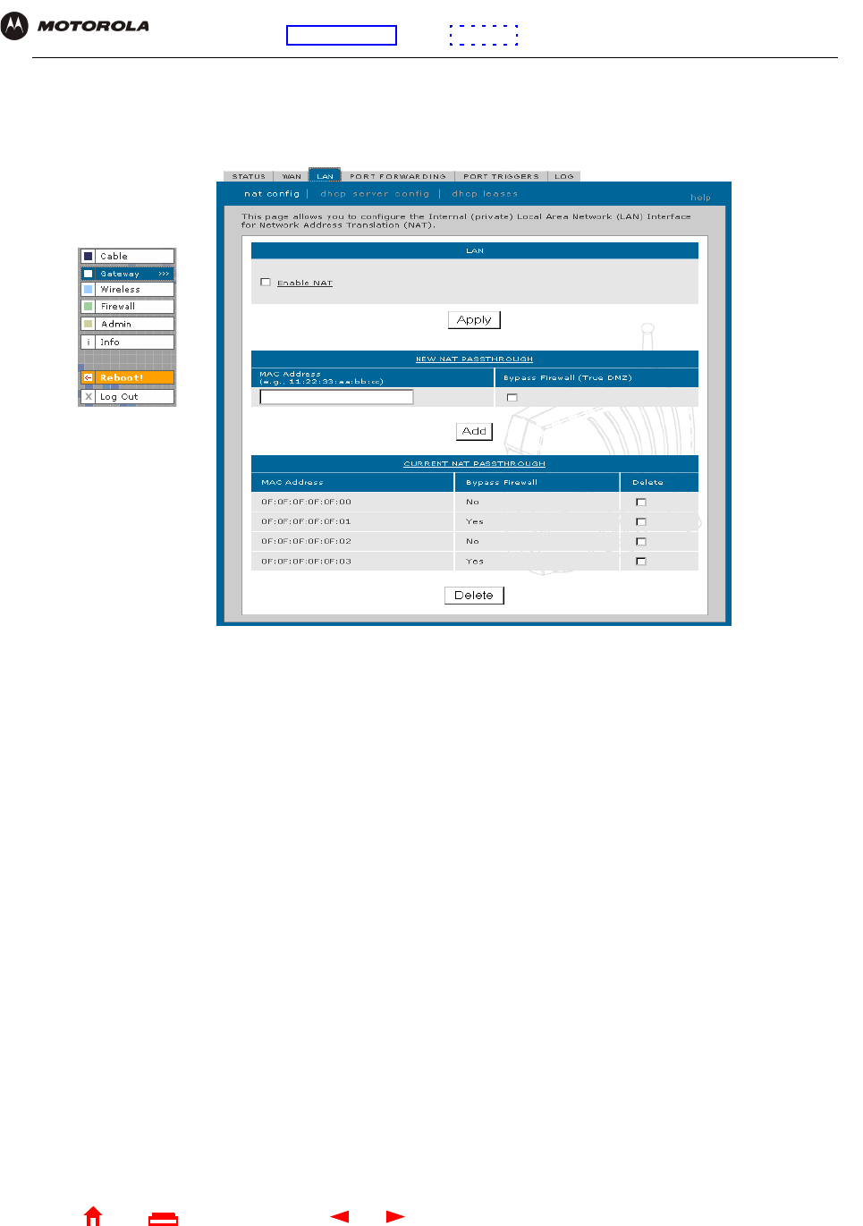
Gateway > LAN — nat config Page
Use this page to enable NAT and add clients to the CURRENT NAT PASSTHROUGH list:
Gateway > LAN — nat config page fields
Field or Button Description
LAN
Enable NAT If enabled, the single HFC IP Address (public IP address) assigned by the cable provider is
mapped to many private IP addresses on the SBG940 LAN.
Apply Click to apply your changes. You must reboot the SBG940.
NEW NAT
PASSTHROUGH
Specifies up to 32 computers as passthrough clients not subject to NAT, using their MAC
addresses.
MAC Address Type the passthrough client MAC address. The format is 16 hexadecimal numerals.
Bypass Firewall
(True DMZ)
Select this box to set the NAT passthrough computer as a DMZ client. Use this setting with
extreme caution because a DMZ client is completely open to Internet hackers.
Add Click to add the MAC address to the CURRENT NAT PASSTHROUGH list.
CURRENT NAT
PASSTHROUGH
Lists the computers on the LAN that are configured for NAT passthrough.
Delete Click to delete the selected MAC address from the NAT passthrough list.
44 SBG940 User Guide
Home
X
ExitPrint
Overview Installation Troubleshooting Contact FAQ Specifications Glossary License
Configuration: Basic Gateway TCP/IP Wireless USB
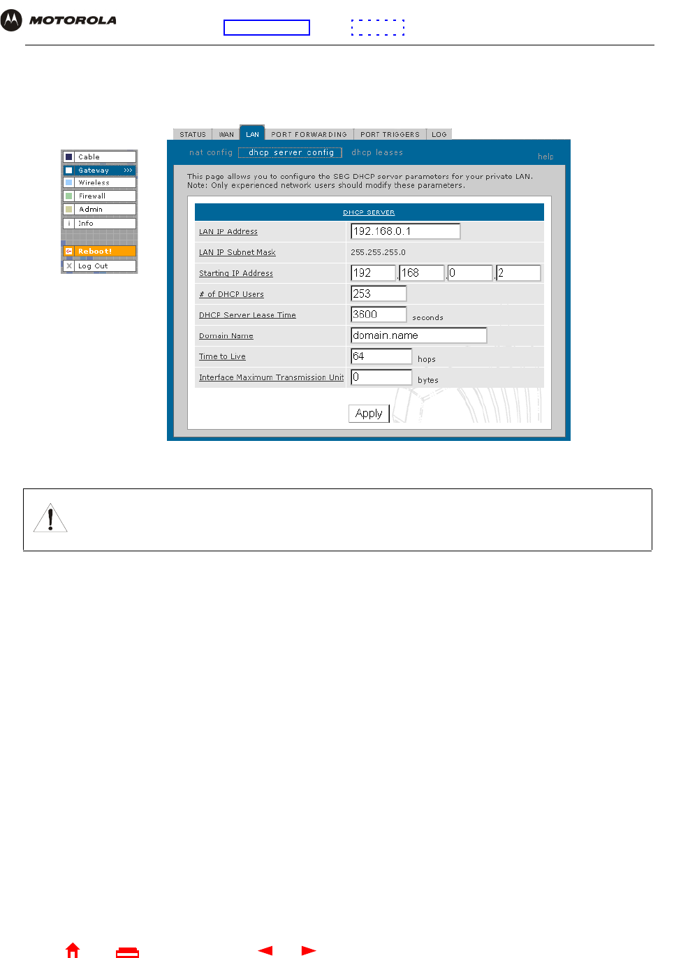
Gateway > LAN — dhcp server config Page
Only experienced network administrators should use this page to perform advanced DHCP server configuration:
CAUTION!
Do not modify these settings unless you are an experienced network administrator with strong
knowledge of IP addressing, subnetting, and DHCP.
Gateway > LAN — dhcp server config page fields
Field Description
LAN IP Address You can type the IP address of the SBG940 for your private LAN. The default is
192.168.0.1.
LAN IP Subnet Mask Displays the subnet mask in dotted-decimal format. The default is 255.255.255.0.
Starting IP Address Enter the starting IP address to be assigned by the SBG940 DHCP server to clients in
dotted-decimal format. The default is 192.168.0.2.
# of DHCP Users Sets the number of clients for the SBG940 DHCP server to assign a private IP address.
There are 253 possible client addresses. The default is 253.
DHCP Server Lease Time Sets the time in seconds that the SBG940 DHCP server leases an IP address to a client.
The default is 3600 seconds (60 minutes).
Domain Name Sets the domain name for the SBG940 LAN. The default is None.
Time To Live Sets the TTL (hop limit) for outbound packets. The default is 64.
Interface Maximum
Transmission Unit
Sets the SBG940 LAN MTU in bytes. The minimum is 68 bytes. The default is 1500 bytes.
Apply Click to apply your changes. You must reboot the SBG940.
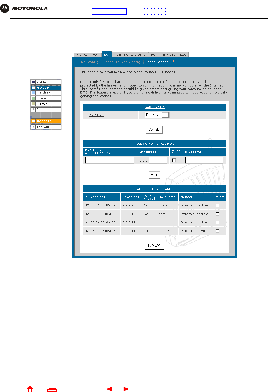
45 SBG940 User Guide
Home
X
ExitPrint
Overview Installation Troubleshooting Contact FAQ Specifications Glossary License
Configuration: Basic Gateway TCP/IP Wireless USB
Gateway > LAN — dhcp leases Page
Use this page to configure DHCP leases:
Gateway > LAN — dhcp leases page fields
Field Description
GAMING DMZ
Enable Gaming DMZ Select this box to designate the selected computer or gaming device as the gaming DMZ
host. For more information, see “Configuring a Gaming DMZ Host”. This can be useful if you
have difficulties running certain applications; typically gaming applications.
(Gaming) DMZ Host The gaming DMZ host is a computer with a reserved IP address designated as the default
DMZ host. Only one gaming DMZ host can be active at once.
The gaming DMZ host is not protected by the firewall. It is open to communication or hacking
from any computer on the Internet. Consider carefully before configuring a computer to be in
the DMZ.
The benefit of using a gaming DMZ host instead of a NAT passthrough host is that a gaming
DMZ host does not require a public IP address as does a NAT passthrough host. If the
application requires a public IP address, configure the computer for NAT passthrough on the
Gateway > LAN — nat config Page.
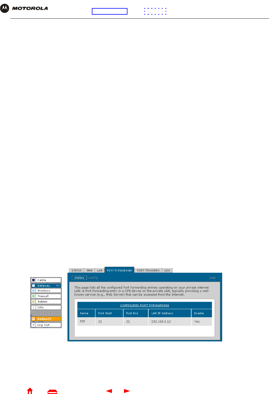
46 SBG940 User Guide
Home
X
ExitPrint
Overview Installation Troubleshooting Contact FAQ Specifications Glossary License
Configuration: Basic Gateway TCP/IP Wireless USB
Gateway > PORT FORWARDING — status Page
Use this page to display the configured port forwarding entries on the SBG940 LAN. The fields are the same as on
the Gateway > PORT FORWARDING — config Page:
RESERVE NEW IP
ADDRESS
You can reserve up to 32 IP addresses assigned by the SBG940 DHCP server for specific
LAN clients. For example, to ensure that they always receive the same private IP address,
you can reserve IP addresses for a private FTP server or gaming DMZ device.
MAC Address Type the MAC address of the DHCP client for which a reserved IP address is required. The
format is 16 hexadecimal numerals.
IP Address Sets the host portion of the reserved IP address for the LAN client having the specified MAC
address. When the LAN client requests an IP address, the SBG940 DHCP server assigns the
client this IP address.
Host Name If your ISP requires a hostname to access their network, enter the hostname provided to you
in the Host Name field.
Add Click Add to reserve a new IP address.
CURRENTLY RESERVED
IP ADDRESSES
Displays all DHCP clients having reserved IP addresses.
MAC Address Displays the client MAC address.
IP Address Displays its reserved IP address
Host Name Displays its host name.
Method Displays dynamic and static lease status. Add or delete dynamic or static lease status in this
field.
Delete Click this box to remove the reserved IP address for the client.
Delete Click this button to remove the reserved IP addresses for clients designated by the Delete
box.
Gateway > LAN — dhcp leases page fields (continued)
Field Description
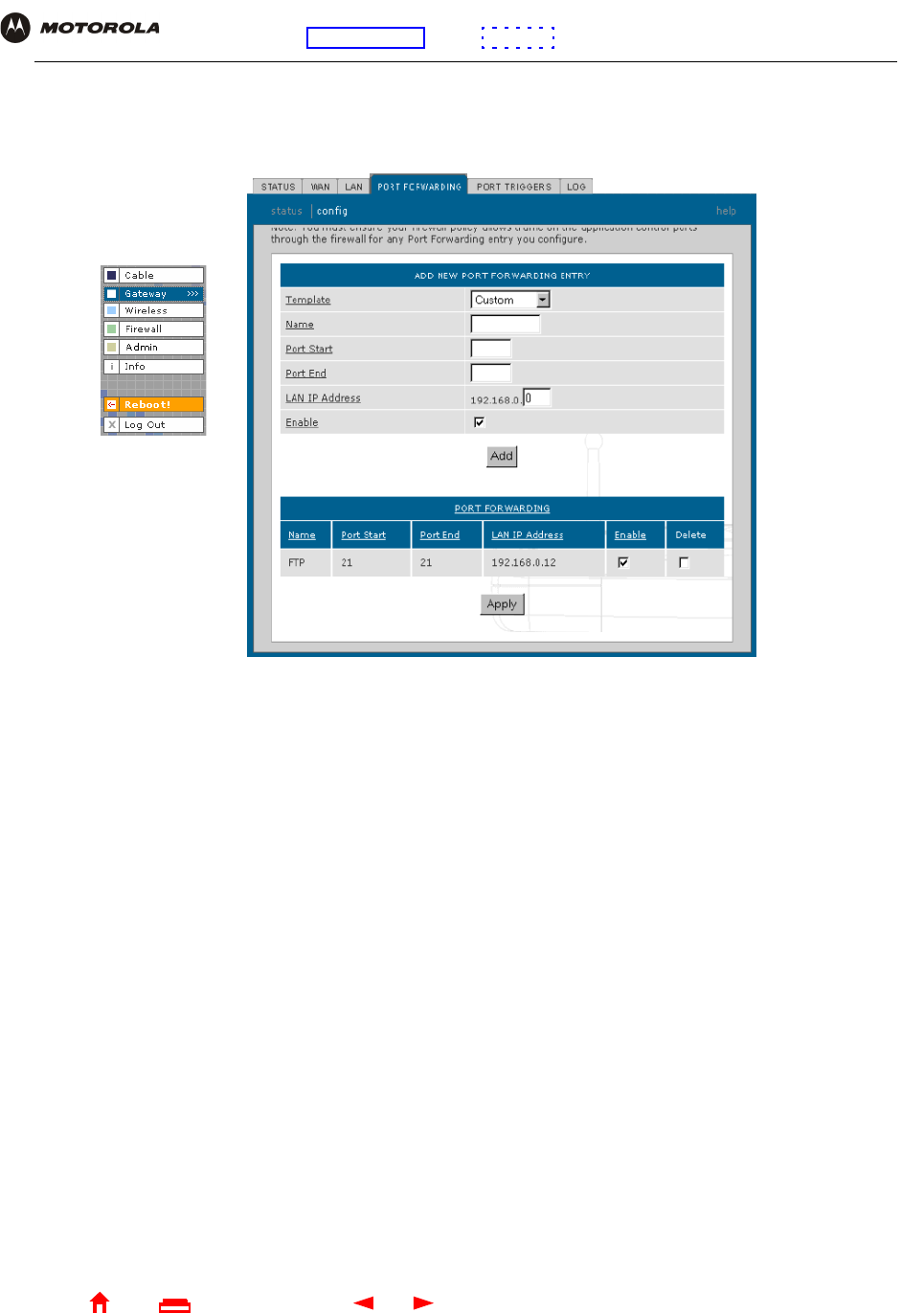
47 SBG940 User Guide
Home
X
ExitPrint
Overview Installation Troubleshooting Contact FAQ Specifications Glossary License
Configuration: Basic Gateway TCP/IP Wireless USB
Gateway > PORT FORWARDING — config Page
Use this page to configure up to 32 virtual servers:
Gateway > PORT FORWARDING — config page fields
Field Description
ADD NEW PORT
FORWARDING ENTRY
You can configure up to 32 virtual servers. If you select Custom, you must set the Name,
Port Start, Port End, and LAN IP Address.
Template If you select a predefined template such as HTTP or FTP, the Name, Port Start, Port End
values are provided. You only need to enter LAN IP Address and change default values
only if necessary.
Name Type a unique identifier for the custom virtual server. The typical practice is to use the
protocol as a unique identifier (for example “ftp”).
Port Start Sets the LAN internal interface port or the start of a port range. Inbound Internet
connection requests are statically mapped to this port. The ports used by some common
applications are:
•FTP 20, 21
•HTTP 80
•NTP 123
•Secure Shell 22
•SMTP e-mail 25
•Telnet 23
Port End If a range of ports is required, sets the end of the port range.

48 SBG940 User Guide
Home
X
ExitPrint
Overview Installation Troubleshooting Contact FAQ Specifications Glossary License
Configuration: Basic Gateway TCP/IP Wireless USB
Gateway > PORT TRIGGERS — predefined Page
When you run a PC application that accesses the Internet, it communicates with a computer on the Internet. In
some applications, especially gaming, the computer on the Internet also communicates with your PC. Because
NAT does not normally allow these incoming connections, the SBG940 supports port triggering.
The SBG940 is preconfigured with port triggering for common applications. You can also configure additional port
triggers if needed. Configuring port triggers for an application requires:
•The application transport protocol — TCP or UDP
•The application port number
You can use the default values for the remaining parameters.
LAN IP Address Sets the private LAN IP address for the port forwarding page. An Internet user must know
the public IP address to access any port forwarding entry you define on the private LAN.
Enable Select this box to enable the port forwarding entries to be accessed through NAT.
Add Click to add the virtual server to the PORT FORWARDING list.
PORT FORWARDING Displays the configured custom virtual servers.
Gateway > PORT FORWARDING — config page fields (continued)
Field Description
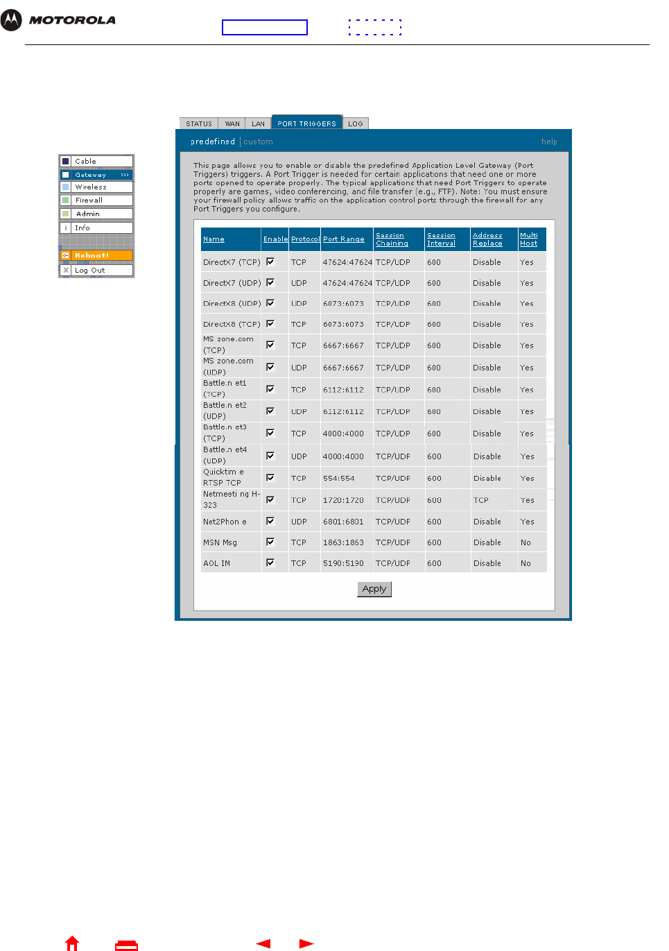
49 SBG940 User Guide
Home
X
ExitPrint
Overview Installation Troubleshooting Contact FAQ Specifications Glossary License
Configuration: Basic Gateway TCP/IP Wireless USB
Only one computer at a time connected to the SBG940 can use an application requiring port triggering. Use this
page to view predefined port triggers:
Gateway > PORT TRIGGERS — predefined page fields
Field Description
Name Displays the unique name for the port triggers. This is typically the protocol name.
Enable Select this box to activate the port triggers for the predefined application.
Protocol Displays the transport protocol for the port trigger — TCP or UDP.
Port Range Displays the port range (From/To) for the port trigger.
Session Chaining Displays the session chaining selection for the port trigger — Disable, TCP, or TCP/UDP.
Session Interval Displays the session interval set for the port trigger.
Address Replace Displays the address replacement method for the port trigger.
Multi Host Displays the multi host selection for the port trigger.
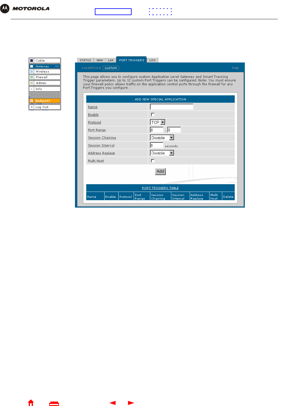
50 SBG940 User Guide
Home
X
ExitPrint
Overview Installation Troubleshooting Contact FAQ Specifications Glossary License
Configuration: Basic Gateway TCP/IP Wireless USB
Gateway > PORT TRIGGERS — custom Page
Use this page to create a custom port trigger:
Gateway > PORT TRIGGERS — custom page fields
Field Description
ADD NEW SPECIAL
APPLICATION
Name Enter the unique name for the port trigger. This is typically the protocol.
Enable Select this box to enable the custom port trigger.
Protocol Sets the transport protocol for the port trigger — TCP or UDP.
Port Range
(From:To)
Sets the port range for the port trigger. Type the start of the range in the left field and the end in
the right field.
Session Chaining Enable session chaining if the application needs to open one or more ports in different ranges to
operate properly. The options are Disable, TCP, or TCP/UDP.
Session Interval Sets the session interval for the application:
•If the port triggers detect traffic on the Port Range within the Session Interval, it is considered
to be related to the initial session.
•If the port triggers detect traffic on the Port Range after the Session Interval expires, it is
considered to be a new and unique session.
Address Replace Sets the address replacement method for the application.
Multi Host Select if appropriate for the application.
Add Click to add the port trigger to the PORT TRIGGERS TABLE.
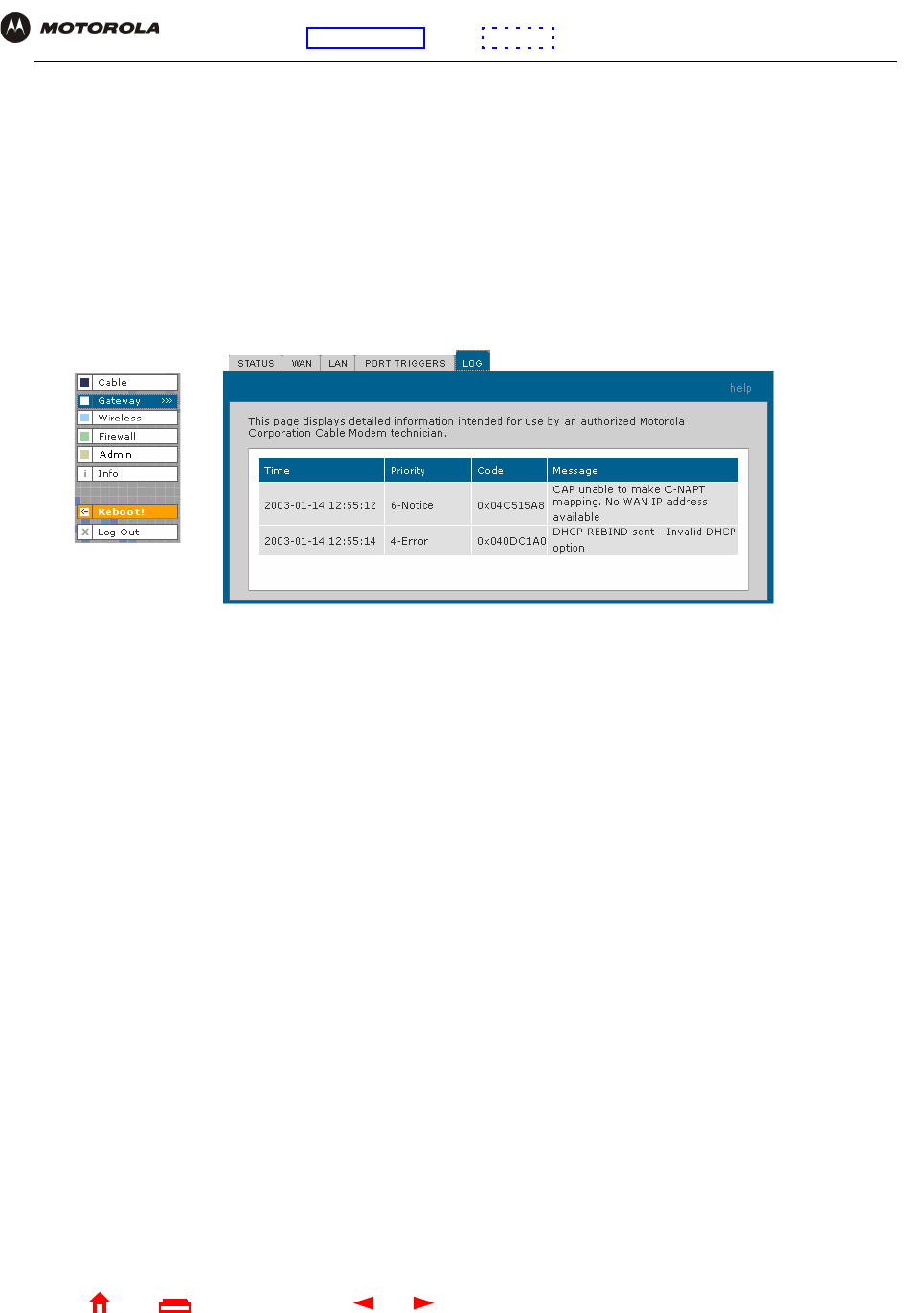
51 SBG940 User Guide
Home
X
ExitPrint
Overview Installation Troubleshooting Contact FAQ Specifications Glossary License
Configuration: Basic Gateway TCP/IP Wireless USB
Gateway > LOG Page
Use this page to view detailed information about the gateway:
PORT TRIGGERS TABLE Lists all port triggers you defined and their parameters.
Priority Port Select the port to have a priority status.
Gateway > LOG page fields
Field Description
Time The date and time in the format yyyy-mm-dd hh:mm:ss
Priority Indicates the importance of the message.
Code Displays a code associated with the message.
Message Describes the event.
Gateway > PORT TRIGGERS — custom page fields (continued)
Field Description
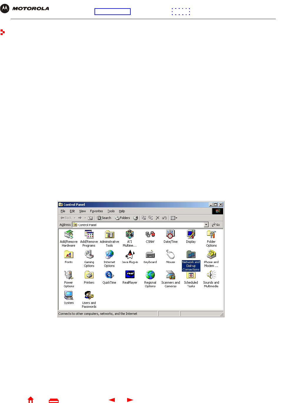
52 SBG940 User Guide
Home
X
ExitPrint
Overview Installation Troubleshooting Contact FAQ Specifications Glossary License
Configuration: Basic Gateway TCP/IP Wireless USB
Configuring TCP/IP
You must be sure all client computers are configured for TCP/IP (a protocol for communication between
computers). Perform one of:
•Configuring TCP/IP in Windows 95, Windows 98, or Windows Me
•Configuring TCP/IP in Windows 2000
•Configuring TCP/IP in Windows XP
•Follow the instructions in your Macintosh or UNIX user manual
After configuring TCP/IP, perform one of the following to verify the IP address:
•Verifying the IP Address in Windows 95, Windows 98, or Windows Me
•Verifying the IP Address in Windows 2000 or Windows XP
•Follow the instructions in your Macintosh or UNIX user manual
Configuring TCP/IP in Windows 95, Windows 98, or Windows Me
1On the Windows Desktop, click Start.
2Select Settings and then Control Panel from the pop-up menus to display the Control Panel window:
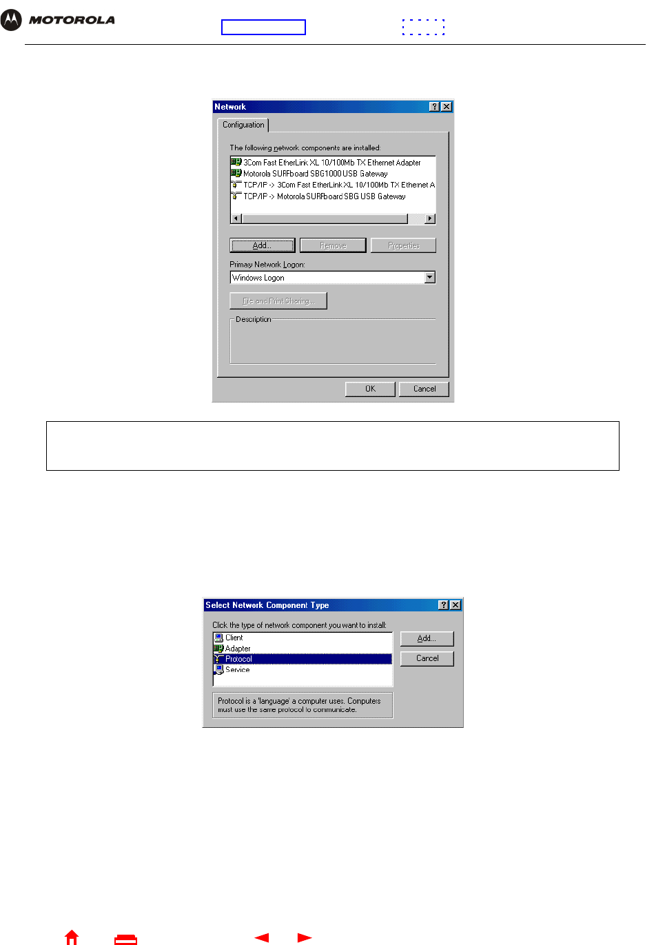
53 SBG940 User Guide
Home
X
ExitPrint
Overview Installation Troubleshooting Contact FAQ Specifications Glossary License
Configuration: Basic Gateway TCP/IP Wireless USB
3Double-click the Network icon to display the Network window:
4Select the Configuration tab.
5Verify that TCP/IP is installed for the adapter used to connect to the SBG940. If TCP/IP is installed, skip to
step 10. If TCP/IP is not installed for the adapter, continue with step 6.
6Select the adapter to use for the SBG940 connection and click Add. The Select Network Component Type
window is displayed:
Although your SBG model number may be different than in the images in this guide, the procedure is
the same.
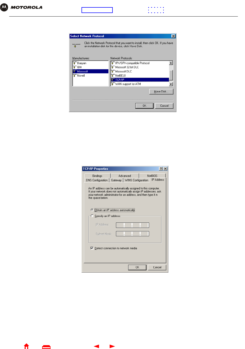
54 SBG940 User Guide
Home
X
ExitPrint
Overview Installation Troubleshooting Contact FAQ Specifications Glossary License
Configuration: Basic Gateway TCP/IP Wireless USB
7Click Protocol and click Add. The Select Network Protocol window is displayed:
8Click Microsoft in the Manufacturers section and click TCP/IP in the Network Protocols section.
9Click OK.
10 Click TCP/IP on the Network window. If there is more than one TCP/IP entry, choose the one for the Ethernet
card or USB port connected to the SBG940.
11 Click Properties. The TCP/IP Properties window is displayed:
12 Click the IP Address tab.
13 Click Obtain an IP address automatically.
14 Click OK to accept the TCP/IP settings.
15 Click OK to close the Network window.
16 Click OK when prompted to restart the computer and click OK again.
When you complete TCP/IP configuration, go to “Verifying the IP Address in Windows 95, Windows 98, or
Windows Me”.
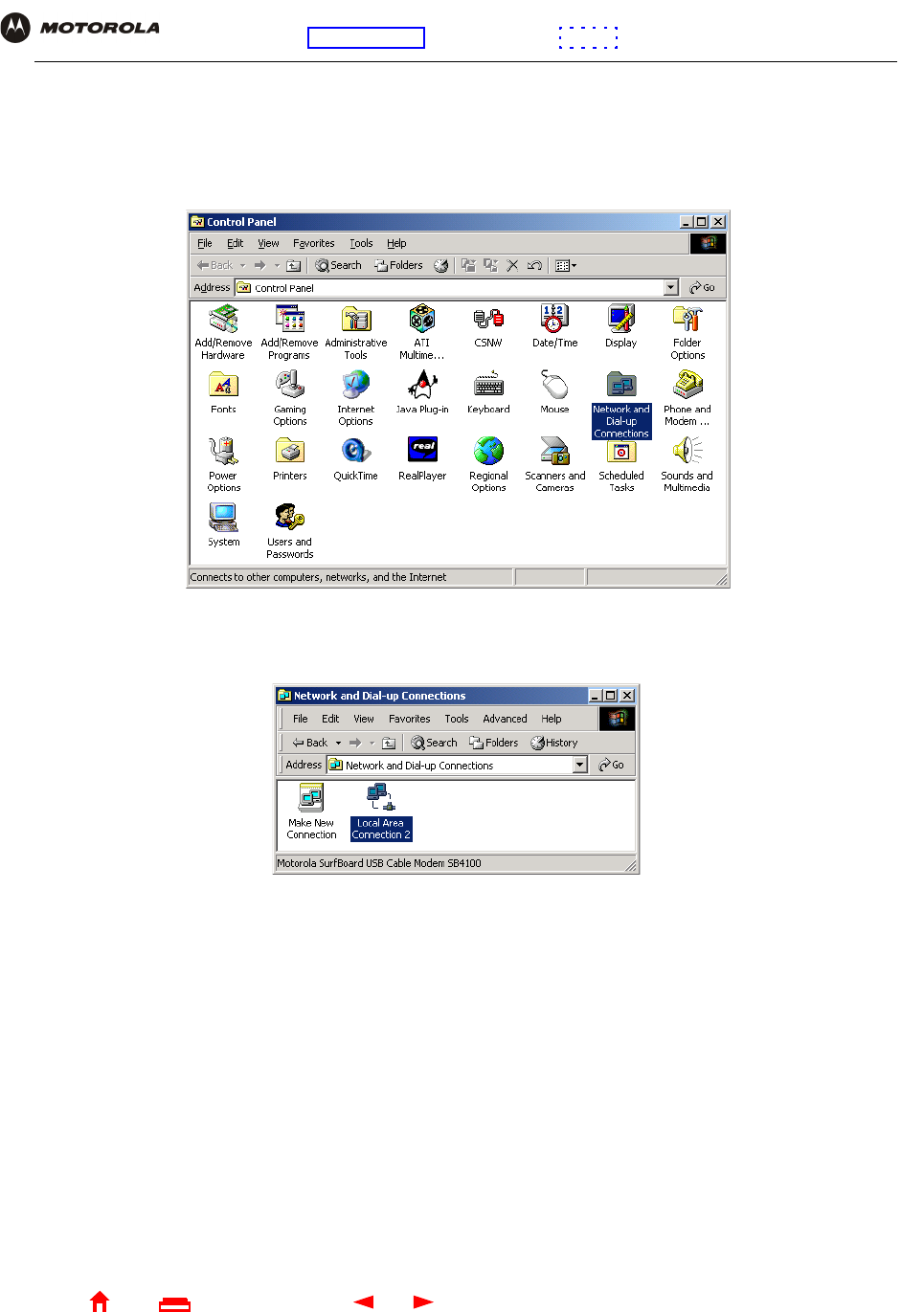
55 SBG940 User Guide
Home
X
ExitPrint
Overview Installation Troubleshooting Contact FAQ Specifications Glossary License
Configuration: Basic Gateway TCP/IP Wireless USB
Configuring TCP/IP in Windows 2000
1On the Windows Desktop, click Start.
2Select Settings and then Control Panel from the pop-up menus to display the Control Panel window:
3Double-click the Network and Dial-up Connections icon to display the Network and Dial-up Connections
window:
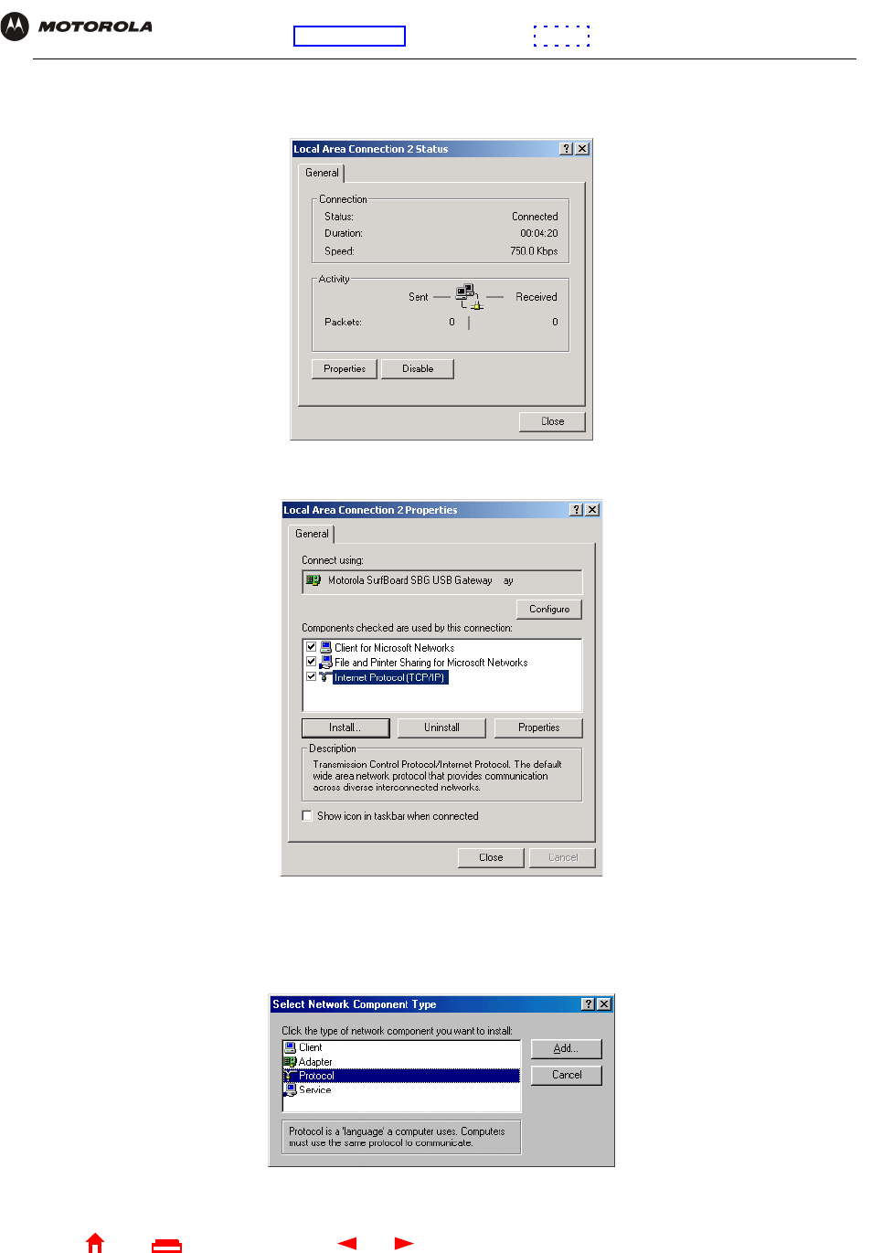
56 SBG940 User Guide
Home
X
ExitPrint
Overview Installation Troubleshooting Contact FAQ Specifications Glossary License
Configuration: Basic Gateway TCP/IP Wireless USB
4Click Local Area Connection number. The value of number varies from system to system. The Local Area
Connection number Status window is displayed:
5Click Properties. Information similar to the following window is displayed:
6If Internet Protocol (TCP/IP) is in the list of components, TCP/IP is installed. You can skip to step 10.
If Internet Protocol (TCP/IP) is not in the list, click Install. The Select Network Component Type window is
displayed:
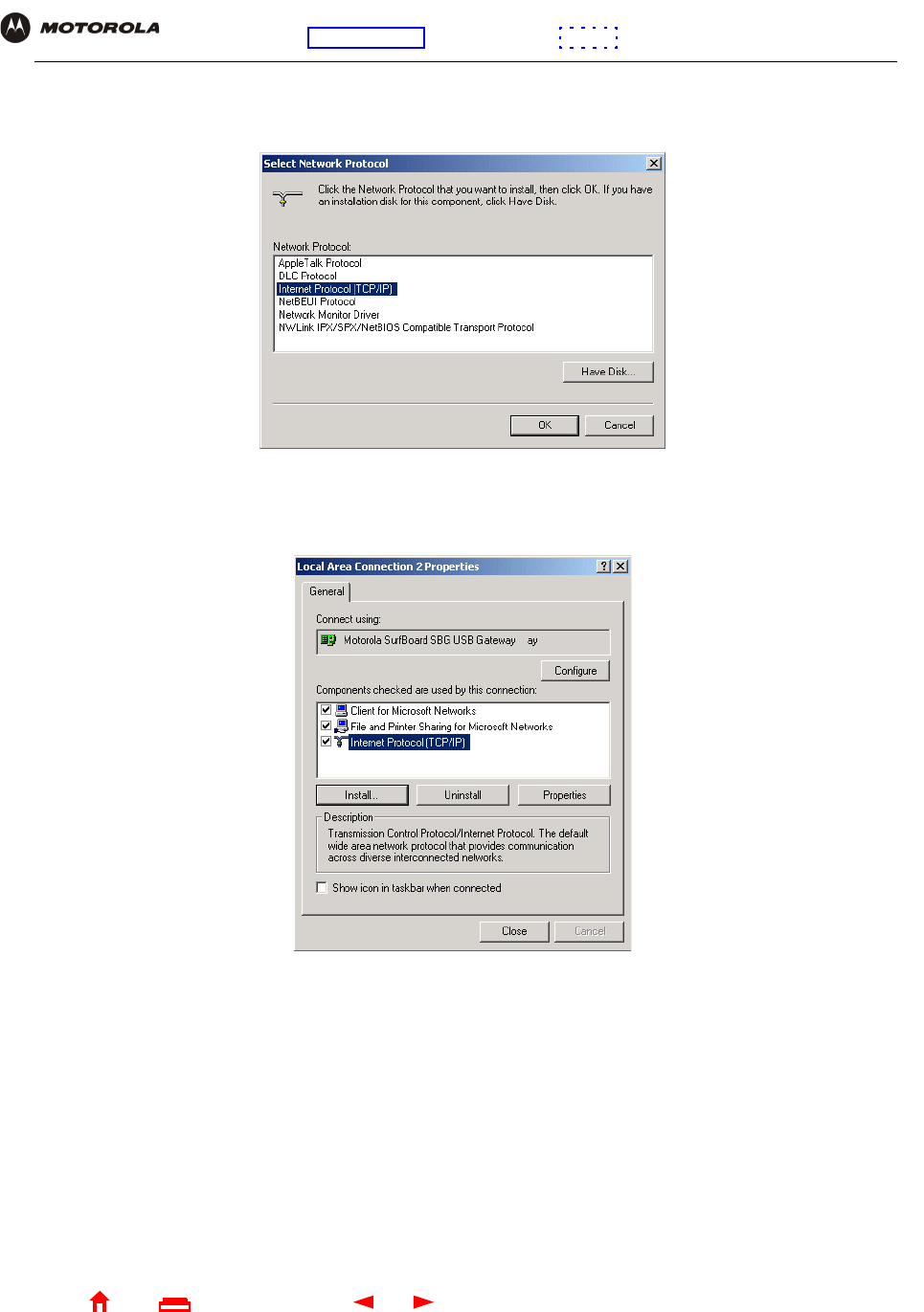
57 SBG940 User Guide
Home
X
ExitPrint
Overview Installation Troubleshooting Contact FAQ Specifications Glossary License
Configuration: Basic Gateway TCP/IP Wireless USB
7Click Protocol on the Select Network Component Type window and click Add. The Select Network Protocol
window is displayed:
8Click Internet Protocol (TCP/IP).
9Click OK. The Local Area Connection number Properties window is re-displayed.
10 Be sure the box next to Internet Protocol (TCP/IP) is selected.
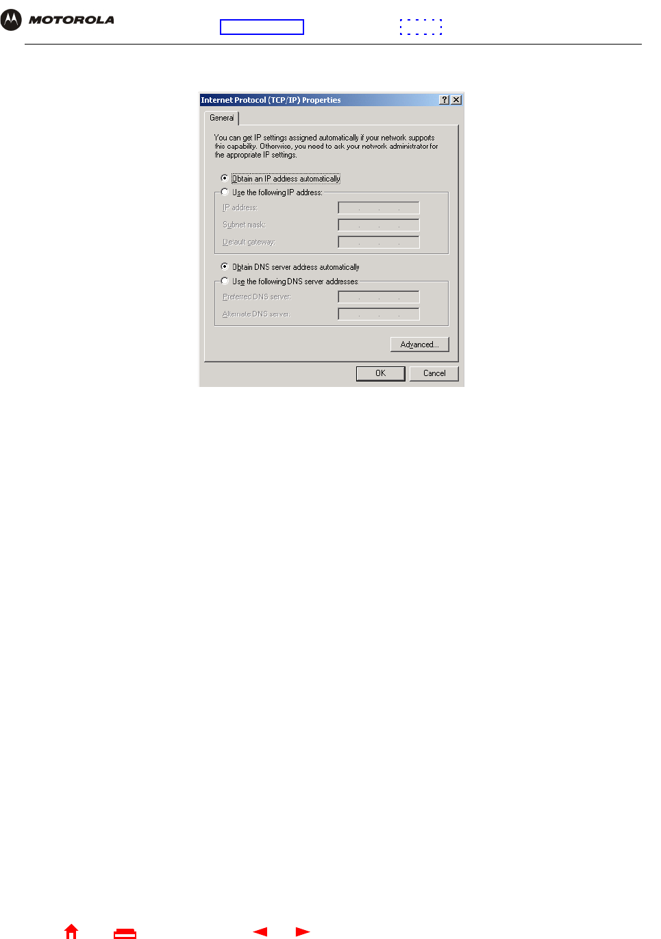
58 SBG940 User Guide
Home
X
ExitPrint
Overview Installation Troubleshooting Contact FAQ Specifications Glossary License
Configuration: Basic Gateway TCP/IP Wireless USB
11 Click Properties. The Internet Protocol (TCP/IP) Properties window is displayed:
12 Be sure Obtain IP address automatically and Obtain DNS server address automatically are selected.
13 Click OK to accept the TCP/IP settings.
14 Click Close to close the Local Area Connection number Properties window.
15 Click OK when prompted to restart the computer and click OK again.
When you complete the TCP/IP configuration, go to “Verifying the IP Address in Windows 2000 or Windows XP”.
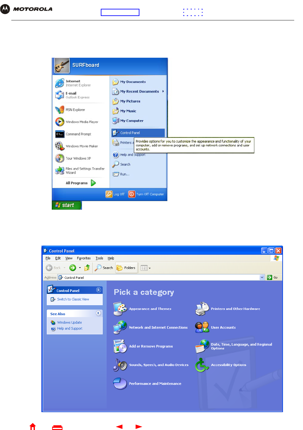
59 SBG940 User Guide
Home
X
ExitPrint
Overview Installation Troubleshooting Contact FAQ Specifications Glossary License
Configuration: Basic Gateway TCP/IP Wireless USB
Configuring TCP/IP in Windows XP
1On the Windows desktop, click Start to display the Start window:
2Click Control Panel to display the Control Panel window. The display varies, depending on the Windows XP
view options. If the display is a Category view as shown below, continue with step 3. Otherwise, skip to
step 5.
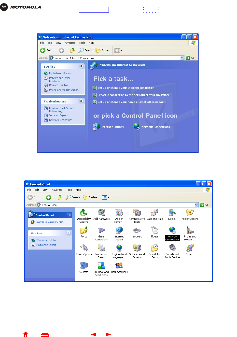
60 SBG940 User Guide
Home
X
ExitPrint
Overview Installation Troubleshooting Contact FAQ Specifications Glossary License
Configuration: Basic Gateway TCP/IP Wireless USB
3Click Network and Internet Connections to display the Network and Internet Connections window:
4Click Network Connections to display the LAN or High-speed Internet connections. Skip to step 7.
5If a classic view similar to below is displayed:
6Double-click Network Connections to display the LAN or High-speed Internet connections.
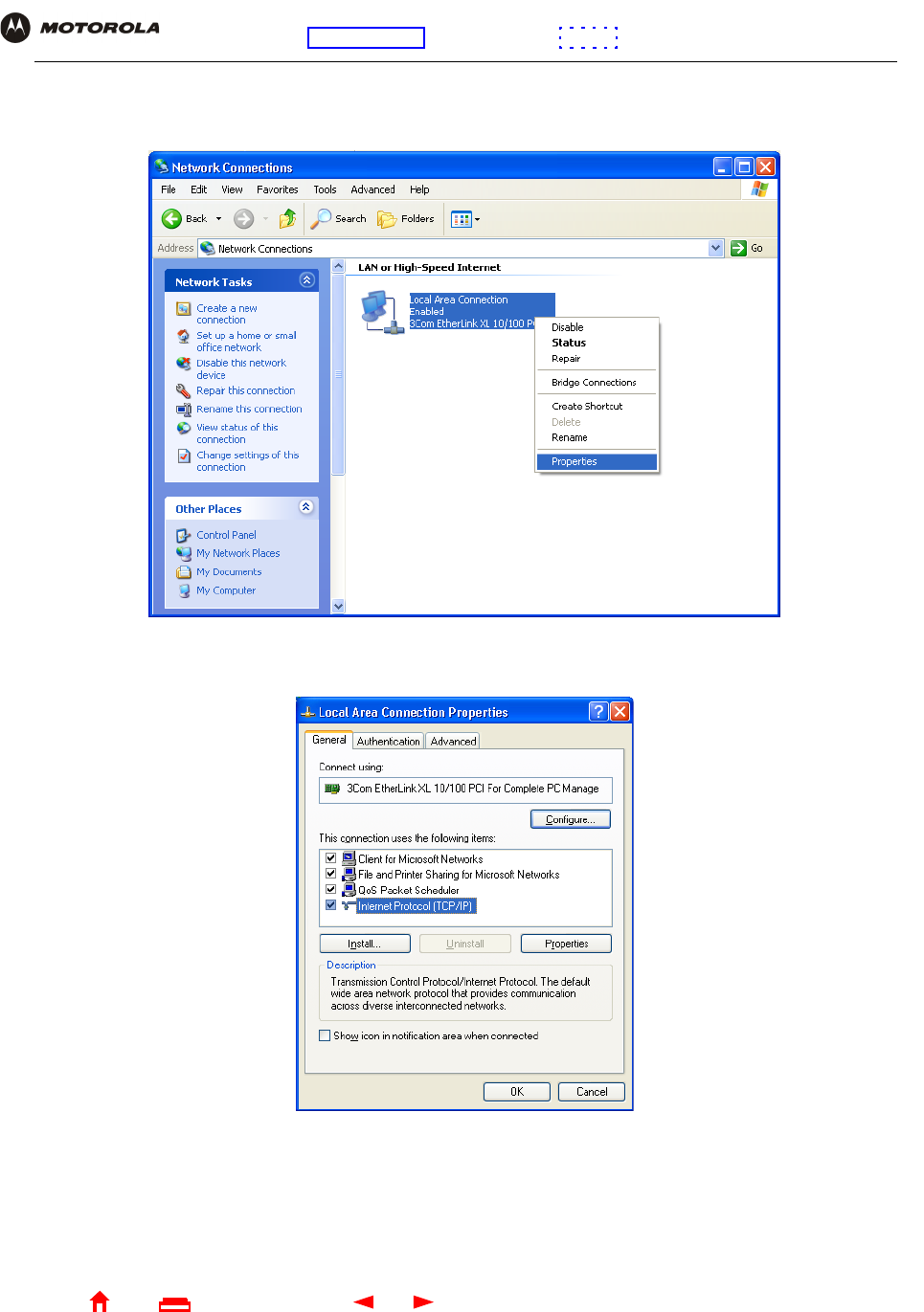
61 SBG940 User Guide
Home
X
ExitPrint
Overview Installation Troubleshooting Contact FAQ Specifications Glossary License
Configuration: Basic Gateway TCP/IP Wireless USB
7Right-click on the network connection. If more than one connection is displayed, be sure to select the one for
your network interface:
8Select Properties from the pop-up menu to display the Local Area Connection Properties window:
9On the Local Area Connection Properties window, be sure Internet Protocol (TCP/IP) is selected. If it is not
selected, select it.
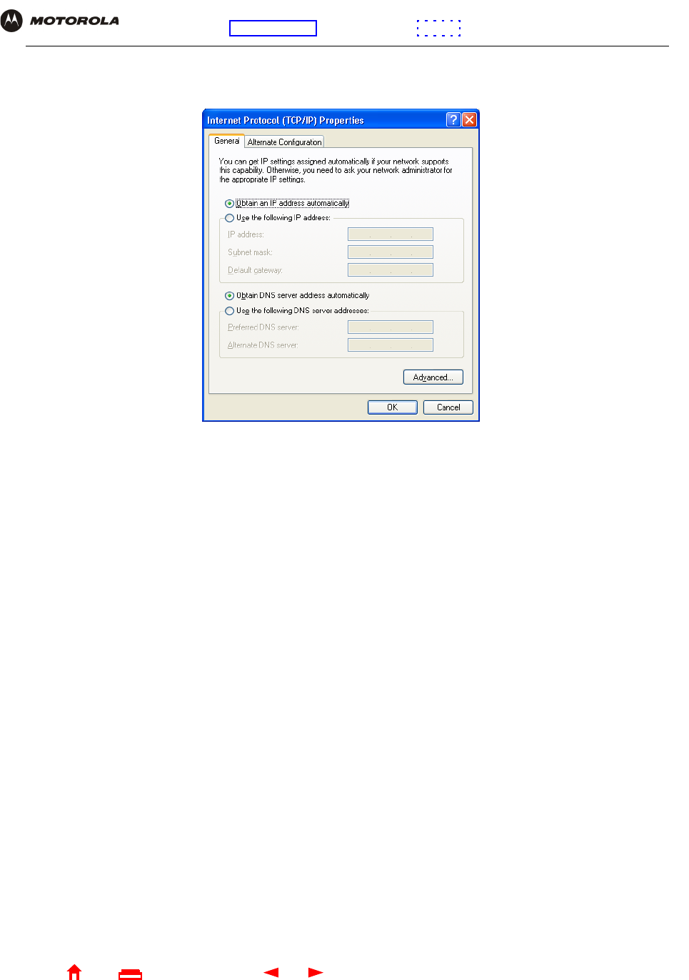
62 SBG940 User Guide
Home
X
ExitPrint
Overview Installation Troubleshooting Contact FAQ Specifications Glossary License
Configuration: Basic Gateway TCP/IP Wireless USB
10 Select Internet Protocol (TCP/IP) and click Properties to display the Internet Protocol (TCP/IP) Properties
window:
11 Verify that the settings are correct, as shown above.
12 Click OK to close the TCP/IP Properties window.
13 Click OK to close the Local Area Connection Properties window.
When you complete the TCP/IP configuration, go to “Verifying the IP Address in Windows 2000 or Windows XP”.
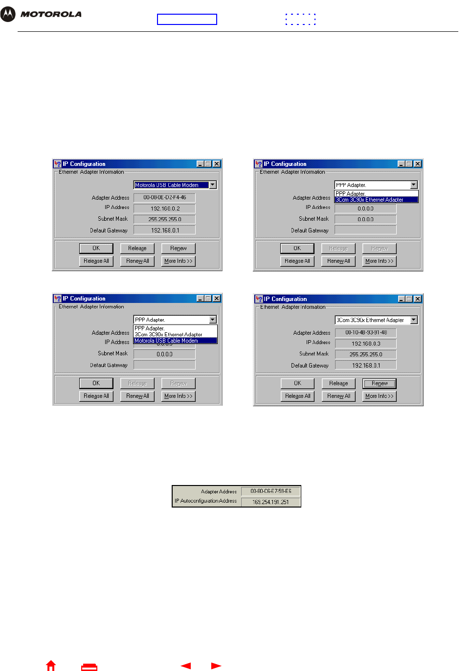
63 SBG940 User Guide
Home
X
ExitPrint
Overview Installation Troubleshooting Contact FAQ Specifications Glossary License
Configuration: Basic Gateway TCP/IP Wireless USB
Verifying the IP Address in Windows 95, Windows 98, or Windows Me
To check the IP address:
1On the Windows Desktop, click Start.
2Select Run. The Run window is displayed.
3Type winipcfg.exe and click OK. The IP Configuration window is displayed. The Ethernet Adapter
Information field will vary depending on the system, as shown in the following examples:
The values for Adapter Address, IP Address, Subnet Mask, and Default Gateway on the PC will be different
than in the images.
In Windows 98, if “Autoconfiguration” is displayed before the IP Address as in the following image, call your
service provider.
4Select the adapter name — the Ethernet card or USB device.
5Click Renew.
6Click OK after the system displays an IP address.
If after performing this procedure the computer cannot access the Internet, call your cable provider for help.
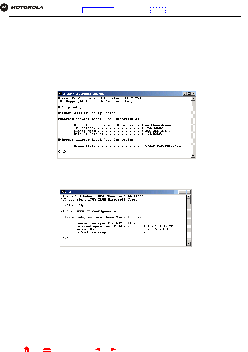
64 SBG940 User Guide
Home
X
ExitPrint
Overview Installation Troubleshooting Contact FAQ Specifications Glossary License
Configuration: Basic Gateway TCP/IP Wireless USB
Verifying the IP Address in Windows 2000 or Windows XP
To check the IP address:
1On the Windows Desktop, click Start.
2Select Run. The Run window is displayed.
3Type cmd and click OK to display a command prompt window.
4Type ipconfig and press ENTER to display the IP configuration. A display similar to the following indicates a
normal configuration:
If an Autoconfiguration IP Address is displayed as in the following window, there is an incorrect connection
between the PC and the SBG940 or there are cable network problems. Check the cable connections and
determine if you can view cable-TV channels on your television:
After verifying the cable connections and proper cable-TV operation, renew the IP address.
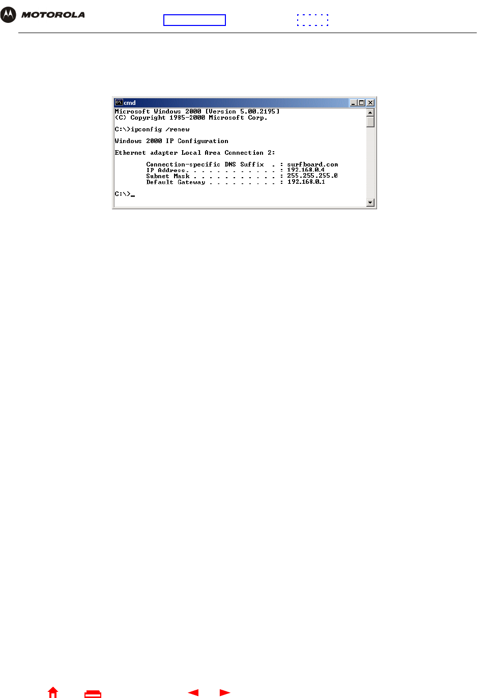
65 SBG940 User Guide
Home
X
ExitPrint
Overview Installation Troubleshooting Contact FAQ Specifications Glossary License
Configuration: Basic Gateway TCP/IP Wireless USB
To renew the IP address:
1Type ipconfig /renew and press ENTER. If a valid IP address is displayed as shown, Internet access should
be available.
2Type exit and press ENTER to return to Windows.
If after performing this procedure the computer cannot access the Internet, call your cable provider for help.