ARRIS SVG1501 Wireless Voice Gateway User Manual Motorola SURFboard
ARRIS Taiwan, Ltd. Wireless Voice Gateway Motorola SURFboard
ARRIS >
Contents
- 1. Manual
- 2. User Manual
Manual

m
Motorola SURFboard®
SVG1501 Wireless Voice Gateway Series
User Guide

i • Safety and Regulatory Information 1
This document is uncontrolled pending incorporation in a Motorola CMS
© 2009 Motorola, Inc. All rights reserved. No part of this publication may be reproduced
in any form or by any means or used to make any derivative work (such as translation,
transformation, or adaptation) without written permission from Motorola, Inc.
MOTOROLA and the Stylized M logo are registered in the US Patent & Trademark
Office. SURFboard is a registered trademark of General Instrument Corporation, a
wholly-owned subsidiary of Motorola, Inc. Microsoft, Windows, Windows NT, Windows
Vista, Internet Explorer, DirectX, and Xbox LIVE are registered trademarks of Microsoft
Corporation; and Windows XP is a trademark of Microsoft Corporation. Linux® is a
registered trademark of Linus Torvalds in the U.S. and other countries. UNIX is a
registered trademark of the Open Group in the United States and other countries.
Macintosh is a registered trademark of Apple Computer, Inc. Adobe, Adobe Acrobat, and
Adobe Acrobat Reader are registered trademarks of Adobe Systems, Inc. All other
product or service names are property of their respective owners .No part of the
contents of this document may be reproduced or transmitted in any form or by any
means without the written permission of the publisher.
Motorola reserves the right to revise this publication and to make changes in content
from time to time without obligation on the part of Motorola to provide notification of
such revision or change. Motorola provides this guide without warranty of any kind,
implied or expressed, including, but not limited to, the implied warranties of
merchantability and fitness for a particular purpose. Motorola may make improvements
or changes in the product(s) described in this manual at any time.

i • Safety and Regulatory Information 1
This document is uncontrolled pending incorporation in a Motorola CMS
i Safety and Regulatory
Information
SAFETY AND REGULATORY INFORMATION
IMPORTANT SAFETY INSTRUCTIONS
When using your equipment, basic safety precautions should always be followed to reduce the
risk of fire, electric shock, and injury to persons, including the following:
• Read all of the instructions listed here and/or in the user manual before you operate this
device. Give particular attention to all safety precautions. Retain the instructions for future
reference.
• This device must be installed and used in strict accordance with manufacturer’s
instructions, as described in the user documentation that is included with the device.
• Comply with all warning and caution statements in the instructions. Observe all warning
and caution symbols that are affixed to this device.
• To prevent fire or shock hazard, do not expose this device to rain or moisture. The device
must not be exposed to dripping or splashing. Do not place objects filled with liquids,
such as vases, on the device.
• This device was qualified under test conditions that included the use of the supplied
cables between systems components. To ensure regulatory and safety compliance, use
only the provided power and interface cables and install them properly.
• Different types of cord sets may be used for connections to the main supply circuit. Use
only a main line cord that complies with all applicable device safety requirements of the
country of use.
• Installation of this device must be in accordance with national wiring codes and conform
to local regulations.
• Operate this device only from the type of power source indicated on the device’s marking
label. If you are not sure of the type of power supplied to your home, consult your dealer
or local power company.
• Do not overload outlets or extension cords, as this can result in a risk of fire or electric
shock. Overloaded AC outlets, extension cords, frayed power cords, damaged or cracked
wire insulation, and broken plugs are dangerous. They may result in a shock or fire hazard.
• Route power supply cords so that they are not likely to be walked on or pinched by items
placed upon or against them. Pay particular attention to cords where they are attached to
plugs and convenience receptacles, and examine the point where they exit from the
device.
• Place this device in a location that is close enough to an electrical outlet to accommodate
the length of the power cord.
• Place the device to allow for easy access when disconnecting the power cord of the
device from the AC wall outlet.
• Do not connect the plug into an extension cord, receptacle, or other outlet unless the plug
can be fully inserted with no part of the blades exposed.
• Place this device on a stable surface.
i • Safety and Regulatory Information 2
This document is uncontrolled pending incorporation in a Motorola CMS
• It is recommended that the customer install an AC surge protector in the AC outlet to
which this device is connected. This is to avoid damaging the device by local lightning
strikes and other electrical surges.
• Postpone installation until there is no risk of thunderstorm or lightning activity in the area.
• Avoid using a telephone (other than a cordless type) during an electrical storm. There may
be a remote risk of electric shock from lightning. For added protection, unplug the device
from the wall outlet and disconnect the cables to avoid damage to this device due to
lightning and power surges.
• Do not cover the device or block the airflow to the device with any other objects. Keep
the device away from excessive heat and humidity and keep the device free from
vibration and dust.
• Wipe the device with a clean, dry cloth. Never use cleaning fluid or similar chemicals. Do
not spray cleaners directly on the device or use forced air to remove dust.
• CAUTION: To reduce the risk of fire, use only No. 26 AWG or larger (e.g., 24 AWG) UL
Listed or CSA Certified Telecommunication Line Cord, or national equivalent.
• Disconnect TNV circuit connector(s) before disconnecting power.
• Disconnect TNV circuit connector before removing cover.
• Do not use this product near water: for example, near a bathtub, washbowl, kitchen sink
or laundry tub, in a wet basement, or near a swimming pool.
• Do not use the telephone to report a gas leak in the vicinity of the leak.
• Upon completion of any service or repairs to this device, ask the service technician to
perform safety checks to determine that the device is in safe operating condition.
• Do not open the device. Do not perform any servicing other than that contained in the
installation and troubleshooting instructions. Refer all servicing to qualified service
personnel.
• This device should not be used in an environment that exceeds 40º C.
SAVE THESE INSTRUCTIONS
Note to CATV System Installer: This reminder is provided to call the CATV system installer’s
attention to Section 820.93 of the National Electric Code, which provides guidelines for proper
grounding and, in particular, specifies that the coaxial cable shield shall be connected to the
grounding system of the building, as close to the point of cable entry as practical.
CARING FOR THE ENVIRONMENT BY RECYCLING
When you see this symbol on a Motorola product, do not dispose of the product
with residential or commercial waste.
Recycling your Motorola Equipment
Please do not dispose of this product with your residential or commercial waste.
Some countries or regions, such as the European Union, have set up systems to
collect and recycle electrical and electronic waste items. Contact your local
authorities for information about practices established for your region. If collection
systems are not available, call Motorola Customer Service for assistance. Please
visit www.motorola.com/recycle for instructions on recycling.

IMPORTANT VOIP SERVICE INFORMATION
When using this VoIP device, you CANNOT make any calls, including an emergency call, and E911
location services WILL NOT be available, under the following circumstances:
• Your broadband ISP connection goes down, is lost or otherwise fails.
• You lose electrical power.
When using this VoIP device, you may be able to make an emergency call to an operator, but E911
location services may not be available under the following circumstances:
• You have changed the physical address of your VoIP device, and you did not update or
otherwise advise your VoIP service provider of this change.
• You are using a non-U.S. telephone number.
• There are delays in making your location information available in or through the local
automatic location information database.
Note: Your service provider, not Motorola, is responsible for the provision of VoIP telephony
services through this equipment. Motorola shall not be liable for, and expressly disclaims, any
direct or indirect liabilities, damages, losses, claims, demands, actions, causes of action, risks, or
harms arising from or related to the services provided through this equipment.
FCC STATEMENTS
FCC INTERFERENCE STATEMENT
This equipment has been tested and found to comply with the limits for a Class B digital device,
pursuant to part 15 of the FCC Rules. These limits are designed to provide reasonable protection
against harmful interference in a residential environment. This equipment generates uses and can
radiate radio frequency energy and, if not installed and used in accordance with the instructions,
may cause harmful interference to radio communications. However, there is no guarantee that
interference will not occur in a particular installation. If this equipment does cause harmful
interference to radio or television reception, which can be determined by turning the device off and
on, the user is encouraged to try to correct the interference by one or more of the following
measures:
• Reorient or relocate the receiving antenna.
• Increase the separation between the device and receiver.
• Connect the equipment into an outlet on a circuit different from that to which the receiver
is connected.
• Consult the dealer or an experienced radio/TV technician for help.
This device complies with part 15 of the FCC Rules. Operation is subject to the following two
conditions: (1) This device may not cause harmful interference, and (2) This device must accept
any interference received, including interference that may cause undesired operation.
FCC CAUTION: Any changes or modifications not expressly approved by Motorola for compliance
could void the user’s authority to operate the equipment.
FCC RADIATION EXPOSURE STATEMENT
This equipment complies with FCC radiation exposure limits set forth for an uncontrolled
environment. To comply with the FCC RF exposure compliance requirements, the separation
distance between the antenna and any person’s body (including hands, wrists, feet and ankles)
must be at least 20 cm (8 inches).
This transmitter must not be co-located or operating in conjunction with any other antenna or
transmitter.
i • Safety and Regulatory Information 3
This document is uncontrolled pending incorporation in a Motorola CMS
i • Safety and Regulatory Information 4
This document is uncontrolled pending incorporation in a Motorola CMS
The availability of some specific channels and/or operational frequency bands are country
dependent and are firmware programmed at the factory to match the intended destinations. The
firmware setting is not accessible by the end user.
INDUSTRY CANADA (IC) STATEMENT
This device complies with RSS-210 of the Industry Canada Rules. Operation is subject to the
following two conditions:
1. This device may not cause interference, and
2. This device must accept any interference, including interference that may cause undesired
operation of the device.
This device is designed to operate with two internal antennas as part of the printed wiring board.
The top facing antenna has a maximum gain of 2dBi and the front facing antenna has a maximum
gain of 4dBi.
To reduce potential radio interference to other users, the antenna types and their gains were so
chosen that the equivalent isotropically radiated power (e.i.r.p) is not more than that permitted for
successful communications.
This Class B digital apparatus complies with Canadian ICES-003.
Cet appareil numérique de la classe B est conforme à la norme NMB-003 du Canada.
IC RADIATION EXPOSURE STATEMENT
IMPORTANT NOTE: This equipment complies with IC radiation exposure limits set forth for an
uncontrolled environment. This equipment should be installed and operated with a minimum
distance of 20 cm between the radiator and your body.
WIRELESS LAN INFORMATION
This device is a wireless network product that uses Direct Sequence Spread Spectrum (DSSS) and
Orthogonal Frequency-Division Multiple Access (OFDMA) radio technologies. The device is
designed to be interoperable with any other wireless DSSS and OFDMA products that comply
with:
• The IEEE 802.11 Standard on Wireless LANs (Revision B and Revision G), as defined and
approved by the Institute of Electrical and Electronics Engineers
• The Wireless Fidelity (Wi-Fi) certification as defined by the Wireless Ethernet
Compatibility Alliance (WECA).
RESTRICTIONS ON THE USE OF WIRELESS DEVICES
In some situations or environments, the use of wireless devices may be restricted by the
proprietor of the building or responsible representatives of the organization. For example, using
wireless equipment in any environment where the risk of interference to other devices or services
is perceived or identified as harmful.
If you are uncertain of the applicable policy for the use of wireless equipment in a specific
organization or environment, you are encouraged to ask for authorization to use the device prior to
turning on the equipment.
The manufacturer is not responsible for any radio or television interference caused by unauthorized
modification of the devices included with this product, or the substitution or attachment of
connecting cables and equipment other than specified by the manufacturer. Correction of the

interference caused by such unauthorized modification, substitution, or attachment is the
responsibility of the user.
The manufacturer and its authorized resellers or distributors are not liable for any damage or
violation of government regulations that may arise from failing to comply with these guidelines.
SECURITY WARNING: This device allows you to create a wireless network. Wireless network
connections may be accessible by unauthorized users. For more information on how to protect
your network, see Setting Up Your Wireless LAN or visit the Motorola website.
INTERNATIONAL DECLARATION OF CONFORMITY
We, Motorola, Inc., 101 Tournament Drive, Horsham, PA 19044, U.S.A., declare under our sole
responsibility that the SURFboard SVG1501 Wireless Voice Gateway Series to which this
declaration relates is in conformity with one or more of the following standards:
EN60950-1 EN 300 328 EN 301 489-1/-17
EN61000-3-2 EN61000-3-3
The following provisions of the Directive(s) of the Council of the European Union:
• EMC Directive 2004/108/EC
• Low Voltage Directive 2006/95/EC
• R&TTE 1999/5/EC
• Waste Electrical and Electronic Equipment (WEEE) Directive 2002/96/EC
• Restriction of the Use of Certain Hazardous Substances in Electrical Equipment (RoHS)
Directive 2002/95/EC
i • Safety and Regulatory Information 5
This document is uncontrolled pending incorporation in a Motorola CMS

i • Safety and Regulatory Information 6
This document is uncontrolled pending incorporation in a Motorola CMS
Contents
Safety and Regulatory Information
Overview
Contact Information ..........................................................................................................................8
SVG1501 Features............................................................................................................................8
SVG1501 LAN Choices.....................................................................................................................9
VoIP Telephone Service with Your SVG1501...........................................................................10
Wireless LAN ...........................................................................................................................10
Wired Ethernet LAN.................................................................................................................12
Front Panel LEDs Overview ...........................................................................................................13
Rear Panel Overview ......................................................................................................................14
MAC Label ......................................................................................................................................15
Getting Started
Before You Begin............................................................................................................................16
Precautions ..............................................................................................................................17
Signing Up for Service..............................................................................................................17
System Requirements .............................................................................................................17
Connecting the SVG1501 to the Cable System .............................................................................18
Cabling the LAN..............................................................................................................................19
Obtaining an IP Address for an Ethernet Connection.....................................................................19
Installing the Telephone for VoIP .............................................................................................19
Configuring TCP/IP..........................................................................................................................20
Configuring TCP/IP in Windows XP .........................................................................................20
Configuring TCP/IP in Windows Vista ......................................................................................20
Verifying the IP Address in Windows XP.................................................................................21
Verifying the IP Address in Windows Vista..............................................................................21
Renewing Your IP Address.............................................................................................................22
Wall Mounting the SVG1501 ..........................................................................................................22
Wall Mounting Template..........................................................................................................23
Basic Configuration
Starting the SVG1501 Configuration Manager (CMGR) .................................................................25
SVG1501 Menu Options Bar ..........................................................................................................26
SVG1501 Submenu Options ....................................................................................................27
Changing the SVG1501 Default Password.....................................................................................27
Restore Factory Defaults .........................................................................................................28
Getting Help....................................................................................................................................28
Exiting the SVG1501 Configuration Manager.................................................................................28
Status Pages
Status Software Page.....................................................................................................................29
Status Connection Page .................................................................................................................30

i • Safety and Regulatory Information 7
This document is uncontrolled pending incorporation in a Motorola CMS
Status Security Page ......................................................................................................................31
Changing the SVG1501 Default Password ..............................................................................31
Status Event Log Page ...................................................................................................................32
Wireless Pages
Wireless 802.11 Radio Page...........................................................................................................33
Wireless 802.11 Primary Network Page ........................................................................................34
Wireless 802.11 Advanced Page....................................................................................................37
Wireless 802.11 Access Control Page ...........................................................................................39
Wireless 802.11 Wi-Fi Multimedia Page ........................................................................................40
Wireless 802.11 Bridging Page ......................................................................................................41
Setting Up Your Wireless LAN .......................................................................................................42
Encrypting Wireless LAN Transmissions .................................................................................42
Installing Wireless Clients ..............................................................................................................43
Installing a Wireless Client for WPA ........................................................................................44
Configuring a Wireless Client for WEP ....................................................................................44
Configuring a Wireless Client with the Network Name (SSID)................................................44
Parental Control Pages
Parental Control User Setup Page ..................................................................................................45
Parental Control Basic Setup Page .................................................................................................47
Parental Control Time of Day Filter Page .......................................................................................48
Parental Control Local Log Page.....................................................................................................49
MTA Pages
MTA Status Page............................................................................................................................50
MTA DHCP Page ............................................................................................................................51
MTA QoS Page ...............................................................................................................................51
MTA Provisioning Page ..................................................................................................................52
MTA Event Log...............................................................................................................................53
Troubleshooting
Solutions .........................................................................................................................................54
Front-Panel LEDs and Error Conditions ..........................................................................................55
Product Specifications
Glossary
Software License

1 • Overview 8
This document is uncontrolled pending incorporation in a Motorola CMS
1 Overview
The Motorola SURFboard® SVG1501 Wireless Voice Gateway is designed for your
home, home office, or small business/enterprise. It can be used in households with one
or more computers capable of wireless connectivity for remote access to the voice
modem.
This user guide provides product overview and setup information for the SVG1501. It
also provides instructions for installing the voice modem and configuring the wireless,
Ethernet, router, DHCP, and security settings.
Contact Information
For any questions or assistance with the SVG1501 Wireless Voice Gateway, contact your
Internet Service provider.
For information on customer service, technical support, or warranty claims; see the
Motorola SVG1501 Software License, Warranty, Safety, and Regulatory Information card
provided with the SVG1501 Wireless Voice Gateway.
SVG1501 Features
The SVG1501 Wireless Voice Gateway combines high-speed Internet access,
networking, and computer security for a home or small-office LAN. It offers the following
features:
• Combination of five separate products in one compact unit — a DOCSIS® 2.0 cable
modem, IEEE 802.11g wireless access point (Wi-Fi© certified), Ethernet
10/100Base-T connections, two VoIP Internet telephone connections, and firewall.
• Data encryption and network access control for wireless transmissions.
• An easy installation and security setup wizard. The Installation Assistant application
on the SVG1501 Installation CD-ROM enables easy connection to the cable network
and setup for security.
• An integrated high-speed cable modem for continuous broadband access to the
Internet and other online services with much faster data transfer than traditional dial-
up or ISDN modems.
• One broadband connection for up to 245 computers to surf the web; all computers
on the LAN communicate as if they were connected to the same physical network.
• An IEEE 802.11g wireless access point to enable laptop users to remain connected
while moving around the home or small office or to connect desktop computers
without installing network wiring. Depending on distance, wireless connection
speeds can match that of Ethernet.

1 • Overview 9
This document is uncontrolled pending incorporation in a Motorola CMS
• Voice-over-Internet Protocol (VoIP) telephone service with two telephone lines
available for reliable voice service with your broadband Internet connection.
• A secure Wi-Fi broadband connection for Wi-Fi enabled devices on your network,
such as your cellular telephone, laptops, printers, PDAs, and desktops.
• Four 10/100Base-T Ethernet uplink ports supporting a half- or full-duplex connection
with auto MDIX capability.
• Universal Serial Bus (USB) connection for a single PC (SVG1501U model only)
• Routing for a wireless LAN (WLAN) or a wired Ethernet LAN; you can connect more
than four computers using hubs and/or switches
• A built-in DHCP server to easily configure a combined wired and/or wireless Class C
private LAN.
• Virtual private network (VPN) pass-through operation supporting IPSec, PPTP, or
L2TP to securely connect remote computers over the Internet.
• SVG1501 Configuration Manager (CMGR) which provides a graphical user interface
(GUI) for easy configuration of necessary wireless, Ethernet, router, DHCP, and
security settings. For information, see SVG1501 Configuration Manager.
• Port Forwarding to configure ports to run applications having special network
requirements.
For the most recent product documentation, visit the Modems & Gateways page on the
Motorola website: http://broadband.motorola.com/consumers/support/default.asp.
SVG1501 LAN Choices
You can connect up to 245 client computers to the SVG1501 using one or any
combination of the following network connections:
• Ethernet local area network (LAN)
• Universal Serial Bus (USB) for SVG1501U model only
• Wireless LAN (IEEE 802.11g that also supports IEEE 802.11b wireless clients)
• Wi-Fi (Wireless Fidelity) connections to Wi-Fi enabled devices
Each computer requires appropriate network adapter hardware and driver software. The
clients on the Ethernet or wireless interfaces can share:
• Internet access with a single Internet Service provider account, subject to Internet
Service provider terms and conditions.
• Files, printers, storage devices, multi-user software applications, games, and video
conferencing.
• Wireless and wired network connections use Windows networking to share files and
peripheral devices such as printers, CD-ROM drives, and external USB drives.

1 • Overview 10
This document is uncontrolled pending incorporation in a Motorola CMS
VoIP Telephone Service with Your SVG1501
The SVG1501 allows you to use the cable Internet connection for VoIP telephone service
with the same features as your traditional telephone service. You must contact a VoIP
service provider for this feature to work with the SVG1501.
You can connect up to two standard telephone lines using the SVG1501, supporting:
• Local and long-distance calling
• Standard telephone features like call hold and mute, caller ID, speed dial, call
forwarding, call waiting, call return, three-way calling, and voice mail
• Telephone modem and fax support
CAUTION: Use only a standard telephone. Digital phones used in many
businesses that connect to a PBX (private branch exchange) do not
operate with the SVG1501.
Wireless LAN
Wireless communication occurs over radio waves rather than a wire. Like a cordless
telephone, a WLAN uses radio signals instead of wires to exchange data. A wireless
network eliminates the need for expensive and intrusive wiring to connect computers
throughout the home or office. Mobile users can remain connected to the network even
when carrying their laptop to different locations in the home or office.
Each computer or other device on a WLAN must be Wi-Fi enabled with either a built-in or
external wireless adapter.
Laptops — Use a wireless notebook adapter in the PCMCIA slot or a wireless USB
adapter.
Desktops — Use a wireless PCI adapter, wireless USB adapter, or compatible product in
the PCI slot or USB port, respectively.
1 • Overview 11
This document is uncontrolled pending incorporation in a Motorola CMS
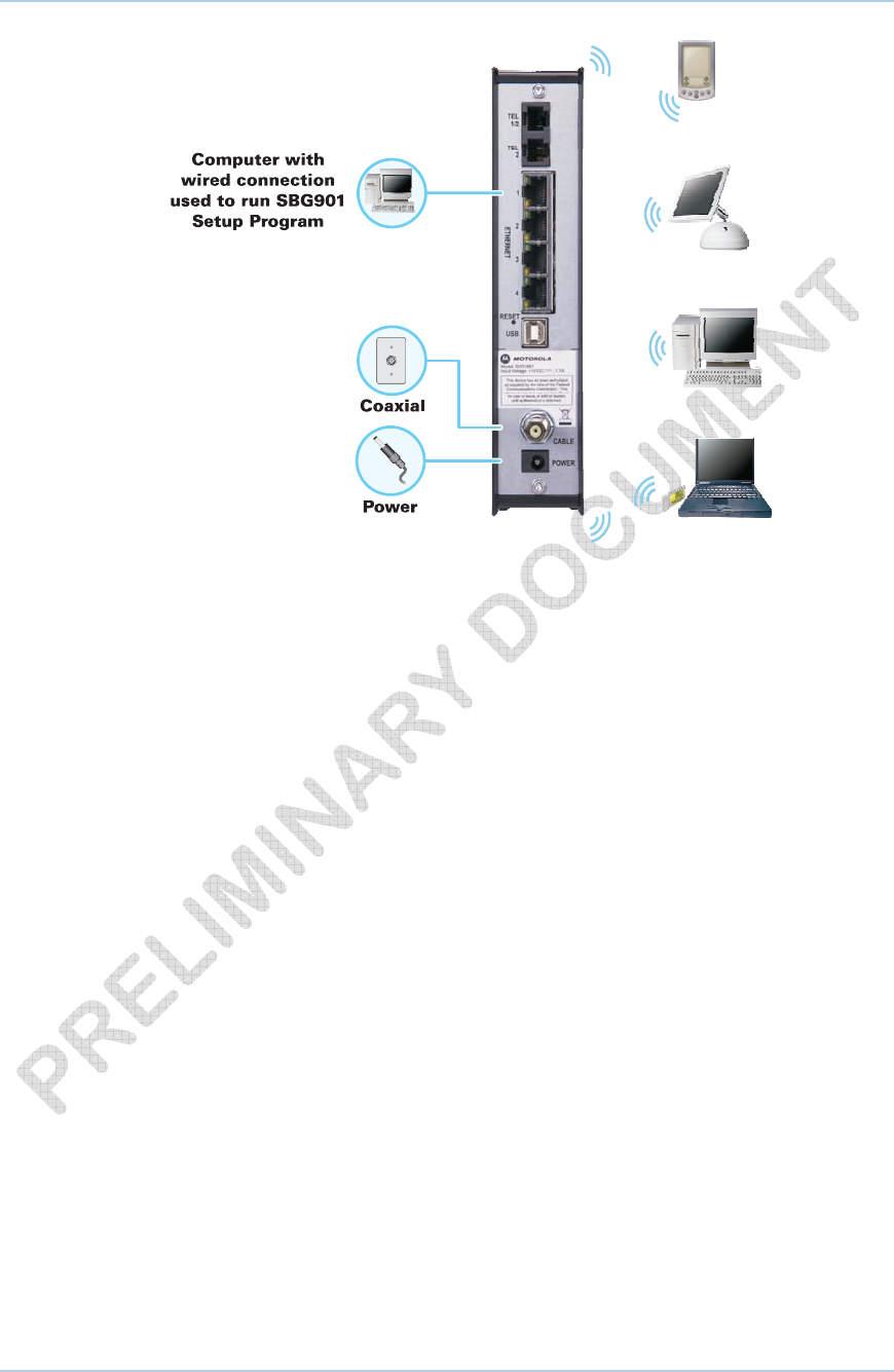
Sample Wireless Network Connections
To set up the SVG1501 on a computer wired to the SVG1501 with an Ethernet
connection, perform the procedures in the section, Wireless Pages. Do not attempt to
configure the SVG1501 over a wireless connection.
Your maximum wireless operation distance depends on the type of materials through
which the signal must pass and the location of your SVG1501 and clients (stations).
Motorola cannot guarantee wireless operation for all supported distances in all
environments.
Wired Ethernet LAN
You can easily connect any PC with an Ethernet LAN port to the SVG1501 Ethernet
connection. Because the SVG1501 Ethernet port supports auto-MDIX, you can use a
straight-through or cross-over cable to connect a hub, switch, or computer. Use
category 5, or better, cabling for all Ethernet connections.
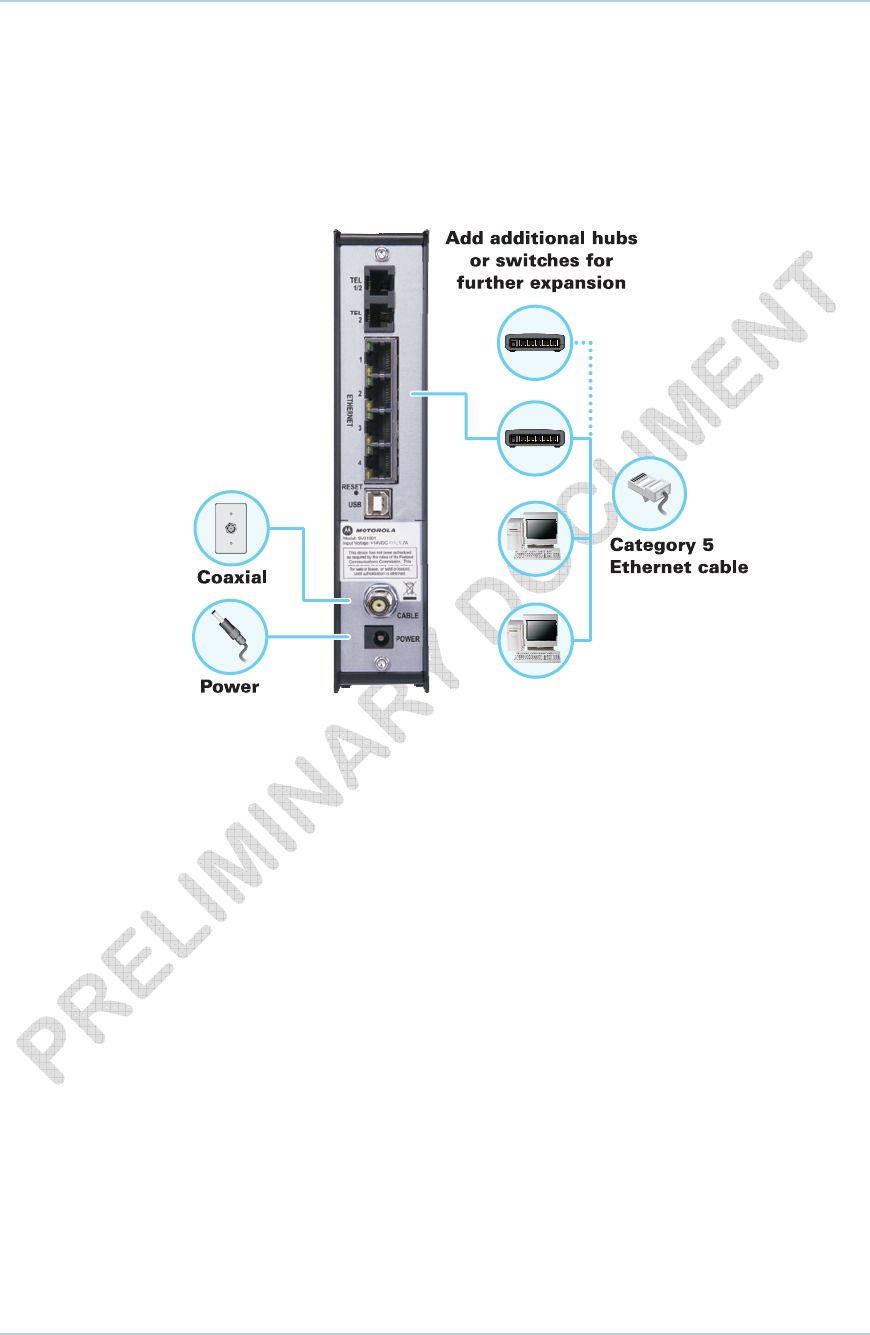
Sample Ethernet to Computer Connection
The physical wiring arrangement has no connection to the logical network allocation of IP
addresses.
A wired Ethernet LAN with more than one computer requires one or more hubs,
switches, or routers. You can:
• Connect a hub or switch to the Ethernet port on the SVG1501.
• Use Ethernet hubs, switches, or routers to connect up to a combination of 245
computers and wireless clients to the SVG1501.
More detailed information on Ethernet cabling is beyond the scope of this document.
1 • Overview 12
This document is uncontrolled pending incorporation in a Motorola CMS
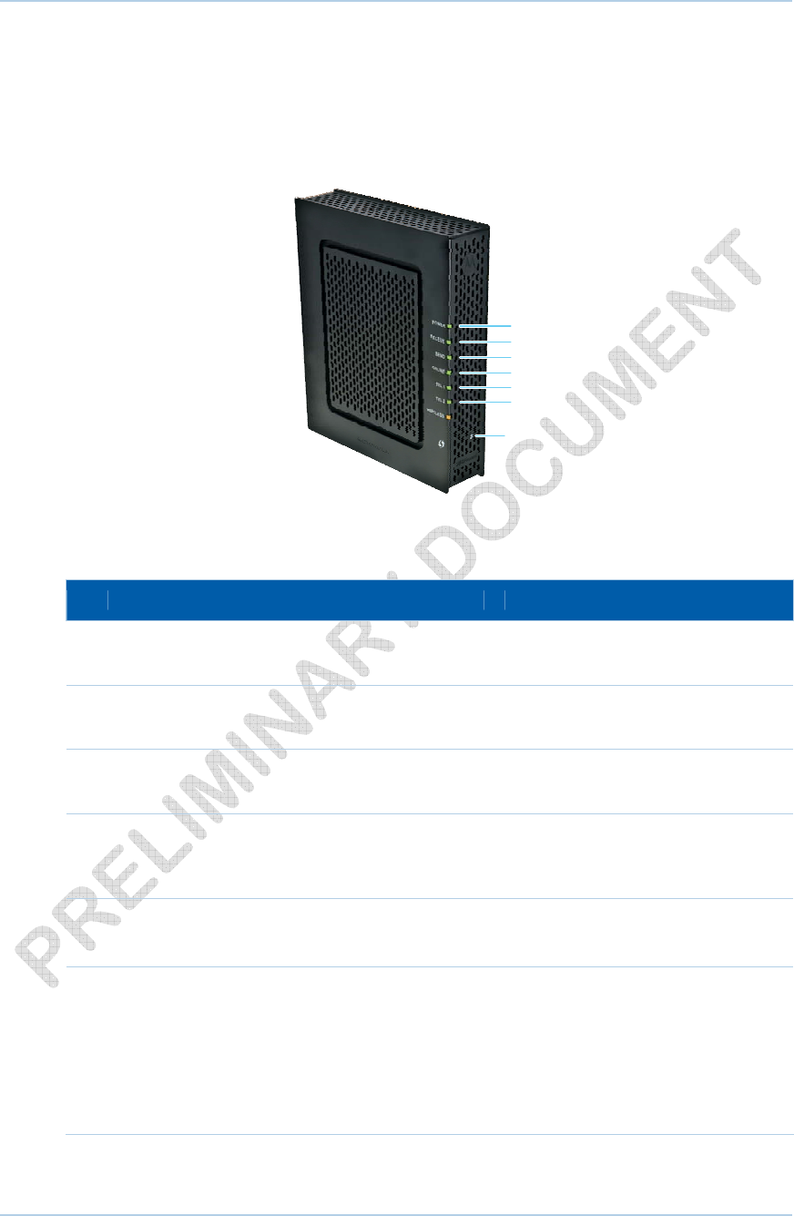
Front Panel LEDs Overview
The SVG1501 front panel contains indicator lights and a Pairing button which is used for
configuring a cellular phone to automatically connect to the SVG1501 wireless network.
The display remains dark until there is a connection or activity on an interface.
1
2
3
4
5
6
Pairing Button
The SVG1501 front panel LED indicators provide the following status information for
power, communications, and errors:
Key LED Flashing On
1 POWER Not applicable — LED does not
flash
Green: Power is properly connected
2 RECEIVE Scanning for a downstream
channel connection
Green: Downstream channel is
connected
3 SEND Scanning for an upstream
channel connection
Green: Upstream channel is
connected
4 ONLINE Scanning for Internet
connection; transmitting or
receiving data over the Internet
Green: Startup process completed
5 TEL1
TEL 2
Telephone is off-hook; dialing or
usage in progress
Green: Telephone is connected and
activated; on-hook
6 WIRELESS Green: Wi-Fi enabled with
encrypted wireless data activity.
Long/short flash indicates
mobile pairing in progress.
Amber: Wi-Fi enabled with
unencrypted wireless data
activity.
Green: Wireless pairing
successfully established between
SVG1501 and another Wi-Fi
enabled device on your network —
cellular telephone, PDA, laptop, etc.
Amber: Mobile pairing successful.
Turns green after 5 minutes.
1 • Overview 13
This document is uncontrolled pending incorporation in a Motorola CMS
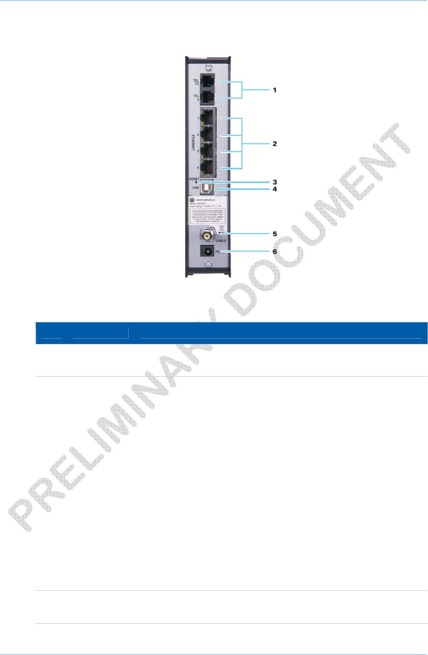
Rear Panel Overview
The SVG1501 rear panel contains the following cabling port and connectors:
Key Item Description
1 TEL1/2
TEL 2
VoIP connection for a single or two-line telephone
VoIP connection for a single telephone
2 ETHERNET
1 2 3 4
Use any Ethernet port to connect an Ethernet-equipped computer, hub,
bridge, or switch using an RJ-45 cable.
Activity LED - Green LED defines the activity of the Ethernet
connector.
When LED is ON, this indicates that there is no data traffic and a
connection is stabilized.
When LED is FLASHING, this indicates that there is data being
transmitted upstream or downstream.
When LED is OFF, this indicates that the unit is not powered or there is
no Ethernet connection.
10/100 LED - Indicates the connection data rate.
When Green LED is ON, this indicates that the connection is connected
at a 100BaseT data rate.
When Amber LED is ON, this indicates that the connection is at a
10BaseT rate.
3 RESET Resets the voice modem, which may take from five to 30 minutes to
find and lock on the appropriate communications channels.
1 • Overview 14
This document is uncontrolled pending incorporation in a Motorola CMS
Key Item Description
4 USB For Windows® only, use the USB port to connect a PC to the
SVG1501U. You cannot connect a Macintosh or UNIX® computer to the
USB port on the SVG1501U.
Note: USB connector is only available on the SVG1501U model.
5 CABLE Connects the SVG1501 to a cable wall outlet.
6 POWER Provides power to the voice modem.
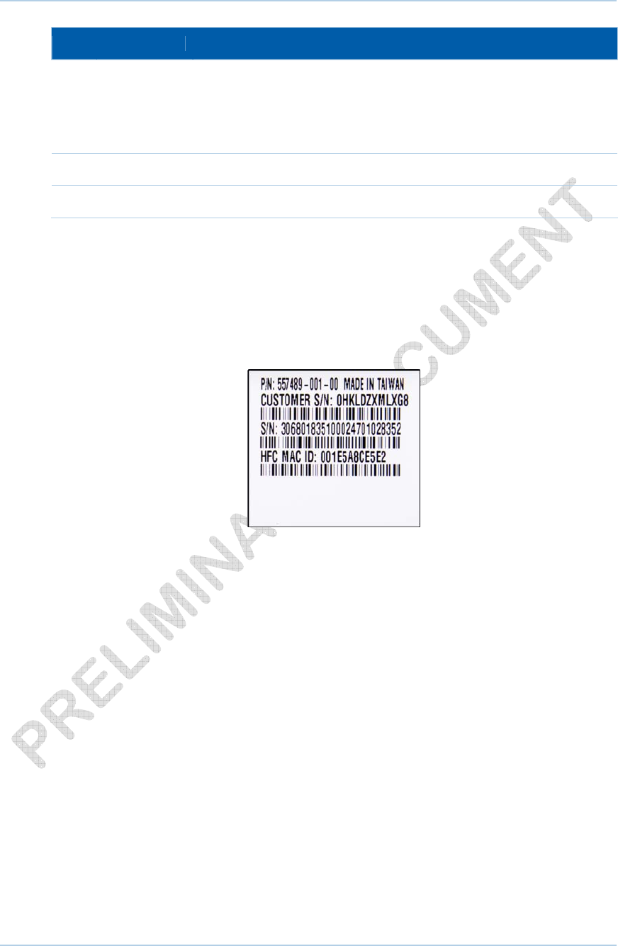
MAC Label
The SVG1501 Media Access Control (MAC) label contains the MAC address which is a
unique, 48-bit value that identifies each Ethernet network device. To receive data
service, you will need to provide the MAC address marked HFC MAC ID to your Internet
Service provider.
1 • Overview 15
This document is uncontrolled pending incorporation in a Motorola CMS
2 Getting Started
This section provides information on setting up and installing the SVG1501 wireless
gateway. For information on WLAN setup, see Setting Up Your Wireless LAN.
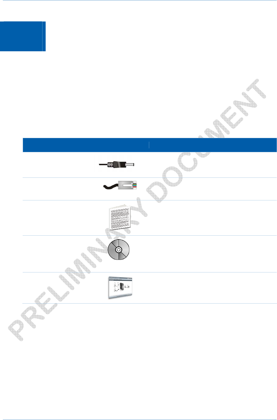
Before You Begin
Before you begin the installation, check that the following items were included with your
Motorola SVG1501 Wireless Cable Modem Gateway:
Item Description
Power cord
Connects the SVG1501 to an AC electrical outlet
10/100Base-T Ethernet
cable Connects the SVG1501 to the network via the
Ethernet port. Cable must be Cat 5 or greater.
Software License &
Regulatory Card
Contains software license, warranty, and safety
information for the SVG1501.
SVG1501 Installation
CD-ROM
Contains the SVG1501/SVG1501U Wi-Fi Wizard,
software license agreement, and multi-language
User Guides. USB drivers are also included for
SVG1501U model only.
SVG1501 Install Sheet
Provides basic information for setting up the
SVG1501
You must have the latest service packs and patches installed on your computer for your
operating system. You will need a 75-ohm coaxial cable with F-type connectors to
connect the SVG1501 to the nearest cable outlet. If a TV is connected to the cable
outlet, you may need a 5 to 900 MHz RF splitter and two additional coaxial cables to use
the TV and the SVG1501.
2 • Getting Started 16
This document is uncontrolled pending incorporation in a Motorola CMS
Determine which connection types you will make to the SVG1501. Check that you have
the required cables, adapters, and adapter software. You may need:
Item Description
Wireless LAN Wireless adapter and driver software for each computer having a wireless
connection
Wired Ethernet Ethernet cables and network interface cards (NICs) with accompanying
installation software
LAN To connect more than one computer via an Ethernet connection to the
SVG1501
USB A USB cable and the SVG1501 Installation CD-ROM containing the
software for USB installation
Precautions
Postpone SVG1501 installation until there is no risk of thunderstorm or lightning activity
in the area.
To avoid potential shock, always unplug the power cord from the wall outlet or other
power source before disconnecting it from the SVG1501 rear panel.
To prevent overheating the SVG1501, do not block the ventilation holes on the sides of
the unit. Do not open the unit. Refer all service to your Internet Service provider.
Signing Up for Service
You must sign up with an Internet Service provider to access the Internet and other
online services. To activate your service, call your local Internet Service provider.
You will need to provide the MAC address marked HFC MAC ID printed on the MAC
Label. You can record it on the SVG1501 Install Sheet.
You should ask your Internet Service provider the following questions:
• Do I have any special system requirements?
• When can I begin to use my SVG1501?
• Are there any files I need to download after connecting the SVG1501?
• Do I need a user name or password to access the Internet or use e-mail?
System Requirements
You can connect Microsoft® Windows®, Macintosh®, UNIX®, or Linux® computers to the
SVG1501 LAN using one of the following connections:
• Ethernet — 10Base-T or 10/100Base-T Ethernet adapter with proper driver software
installed.
2 • Getting Started 17
This document is uncontrolled pending incorporation in a Motorola CMS
2 • Getting Started 18
This document is uncontrolled pending incorporation in a Motorola CMS
• Wireless — Any IEEE 802.11g or IEEE 802.11b device. This includes any Wi-Fi
certified wireless device, such as a cellular telephone equipped with this feature.
In addition, your computer must meet the following requirements:
• Computer with Pentium© class or better processor
• Windows XP, Windows Vista, Macintosh, Linux, or UNIX operating system with
available operating system CD-ROM
You can use any web browser such as Microsoft® Internet Explorer, Netscape
Navigator®, or Mozilla® Firefox® with the SVG1501 wireless gateway.
Connecting the SVG1501 to the Cable System
Note: Before starting, be sure the computer is turned on and the
SVG1501 is unplugged.
1. Connect one end of the coaxial cable to the cable outlet or splitter.
2. Connect the other end of the coaxial cable to the cable connector on the SVG1501.
Hand-tighten the connectors to avoid damaging them.
3. Plug the power cord into the power connector on the SVG1501.
4. Plug the power cord into the electrical outlet.
This turns on the SVG1501. You do not need to unplug it when not in use. The
first time you plug in the SVG1501, allow it five to 30 minutes to find and lock
on the appropriate communications channels.
5. Check that the LEDs on the front panel cycle through the following sequence:
SVG1501 LED Activity During Startup
LED Description
POWER Turns on when AC power is connected to the SVG1501.
Indicates that the power is connected properly.
RECEIVE Flashes while scanning for the downstream receive channel.
Changes to solid green when the receive channel is locked.
SEND Flashes while scanning for the upstream send channel.
Changes to solid green when the send channel is locked.
ONLINE Flashes during SVG1501 registration and configuration.
Changes to solid green when the SVG1501 is registered.

2 • Getting Started 19
This document is uncontrolled pending incorporation in a Motorola CMS
Cabling the LAN
After connecting to the cable system, you can connect your wired Ethernet LAN. Some
sample connections are shown in Wired Ethernet LAN. On each networked computer,
you must install proper drivers for the Ethernet adapter. Detailed information about
network cabling is beyond the scope of this document.
Obtaining an IP Address for an Ethernet
Connection
To obtain the IP address for your computer’s network interface, use one of the following
options:
• Retrieve the statically defined IP address and DNS address
• Automatically retrieve the IP address using the Network DHCP server
The Motorola SVG1501 gateway provides a DHCP server on its LAN. It is recommended
that you configure your LAN to obtain the IPs for the LAN and DNS server automatically.
Installing the Telephone for VoIP
The SVG1501 allows you to use your cable Internet connection for VoIP telephone
service. You must contact a VoIP service provider for this feature to work with the
SVG1501. You can connect up to two standard telephone lines using your SVG1501.
CAUTION: To reduce the risk of fire, use only No. 26 or larger UL
Listed or CSA Certified Telecommunication Line Cord or national
equivalent to connect a telephone line to your SVG1501.
Contact your service provider before connecting your Motorola
SVG1501 to your existing telephone wiring. Do not connect the
telephone wire to a traditional telephone (PSTN) service.
Be sure the phone connectors are neither connected together nor
connected to wall jacks on the same network.
Use only a standard telephone. In many businesses, digital phones that
connect to a private branch exchange (PBX) do not operate with the
SVG1501.
Connect your telephone by plugging a phone wire into the TEL 1/2 connector. You can
also connect a second telephone line to the TEL 2 connector. A two-line telephone may
be connected to TEL 1/2.

2 • Getting Started 20
This document is uncontrolled pending incorporation in a Motorola CMS
Configuring TCP/IP
Make sure all client computers are configured for TCP/IP, which is a protocol for
communication between computers. Perform one of the following for the operating
system you are running:
• Configuring TCP/IP in Windows XP
• Configuring TCP/IP in Windows Vista
• For UNIX systems, follow the instructions in the applicable UNIX user
documentation.
After configuring TCP/IP on your computer, perform one of the following to verify the IP
address:
• Verifying the IP Address in Windows XP
• Verifying the IP Address in Windows Vista
For UNIX systems, follow the instructions in the applicable UNIX user documentation.
Your cable provider may provide additional instructions to set up your computer.
Configuring TCP/IP in Windows XP
1. Open the Control Panel.
2. Double-click Network Connections to list the Dial-up and LAN or High-Speed
Internet connections.
3. Right-click the network connection for your network interface.
4. Select Properties from the drop-down menu to display the Local Area Connection
Properties window. Be sure Internet Protocol (TCP/IP) is checked.
5. Select Internet Protocol (TCP/IP) and click Properties to display the Internet
Protocol (TCP/IP) Properties window.
6. Select Obtain an IP address automatically and Obtain DNS server address
automatically.
7. Click OK to save the TCP/IP settings and exit the TCP/IP Properties window.
8. Close the Local Area Connection Properties window and then exit the Control Panel.
9. When you complete the TCP/IP configuration, go to Verifying the IP Address in
Windows XP.
Configuring TCP/IP in Windows Vista
1. Open the Control Panel.
2. Double-click Network and Internet to display the Network and Internet window.
3. Double-click Network and Sharing Center to display the Network and Sharing
Center window.
4. Click Manage network connections to display the LAN or High-Speed Internet
connections window.
5. Right-click the network connection for your network interface.

2 • Getting Started 21
This document is uncontrolled pending incorporation in a Motorola CMS
6. Select Properties to display the Local Area Connection Properties window.
7. Vista may prompt you to allow access to the Network Properties Options. If you see
the prompt, User Account Control -- Windows needs your permission to continue,
click Continue.
8. Select Internet Protocol Version4 (TCP/IPv4) and click Properties to display the
Internet Protocol Version 4 (TCP/IPv4) Properties window.
9. Select Obtain an IP address automatically and Obtain DNS server address
automatically.
10. Click OK to save the TCP/IP settings and close the Internet Protocol Version 4
(TCP/IPv4) Properties window.
11. Click OK to close the Local Area Connection Properties window.
12. Close the remaining windows and exit the Control Panel.
13. When you complete the TCP/IP configuration, go to Verifying the IP Address in
Windows Vista.
Verifying the IP Address in Windows XP
To check the IP address:
1. On the Windows Desktop, click Start.
2. Select Run. The Run window is displayed.
3. Type cmd and click OK
4. Type ipconfig and press ENTER to display your IP configuration.
If an Autoconfiguration IP Address is displayed, this indicates cable network problems or
an improper connection between your computer and the SVG1501 cable modem.
Check the following:
• Your cable connections
• Whether you can see cable-TV channels on your television
After successfully verifying your cable connections and proper cable-TV operation, you
can renew your IP address.
Verifying the IP Address in Windows Vista
Do the following to verify the IP address:
1. On the Windows Desktop, click Start.
2. Click All Programs.
3. Click Accessories.
4. Click Run to display the Run window.
5. Type cmd and click OK to open a command prompt window.
6. Type ipconfig and press Enter to display the IP Configuration.
If an Auto-configuration IP Address is displayed, this indicates an improper connection
between your computer and the SVG1501 cable modem, or there are broadband
network problems.

2 • Getting Started 22
This document is uncontrolled pending incorporation in a Motorola CMS
Renewing Your IP Address
To renew your IP address in Windows XP or Windows Vista:
1. Open a command prompt window.
A. From the Windows Taskbar, click Start to open the Start menu.
B. Click Run to open the Run dialog.
C. Type cmd in the Open entry box and click OK.
2. Type ipconfig /renew and press ENTER. A valid IP address should appear
indicating that Internet access is available.
3. Type exit and press ENTER to close the command prompt window.
If after performing this procedure your computer cannot access the Internet, call your
cable provider for help.
Wall Mounting the SVG1501
Do the following to mount the SVG1501 on the wall:
• Locate the unit as specified by the local or national codes governing residential or
business cable TV and communications services.
• Follow all local standards for installing a network interface unit/network interface
device (NIU/NID).
If possible, mount the unit to concrete, masonry, a wooden stud, or some other very
solid wall material. Use anchors if necessary (for example, if you must mount the unit on
drywall).
CAUTION: Before drilling holes, check the structure for potential
damage to water, gas, or electrical lines.
Make sure the AC power plug is disconnected from the wall outlet and all cables are
removed from the back of the SVG1501 before starting the installation.
You can mount the SVG1501 horizontally or vertically. Do the following to mount your
SVG1501 on the wall:
1. Print a coy of the Wall Mounting Template.
2. Measure the printed template with a ruler to ensure that it is the correct size.
3. Use a center punch to mark the center of the holes.
4. On the wall, locate the marks for the mounting holes.
5. Drill the holes to a depth of at least 1 1/2 inches (3.8 cm). Use M3.5 x 38 mm (#6 x
11/2 inch) screws with a flat underside and maximum screw head diameter of 9.0
mm to mount the SVG1501.
6. Using a screwdriver, turn each screw until part of it protrudes from the wall, as
shown in the following wall mounting screw dimensions illustration.

2 • Getting Started 23
This document is uncontrolled pending incorporation in a Motorola CMS
6.0 mm (.24 inches) maximum
9.0 mm (.35 inches) maximum
2.5 mm (.10 inches).
There must be .10 inches (2.5 mm) between the wall and the underside of the screw
head.
7. Place the SVG1501 so the keyholes on the back of the unit are aligned above the
mounting screws.
8. Slide the SVG1501 down until it stops against the top of the keyhole opening.
After mounting, reconnect the coaxial cable input and Ethernet connection. Plug the
power cord into the +12VDC connector on the cable modem and the electrical outlet.
Route the cables so that they are not a safety problem.
Wall Mounting Template
You can print the following page to use as a wall mounting template.
Be sure you print it at 100% scale. In the Print dialogue window, be sure that Scale to
paper size is set to No scaling in the Print dialog box.
Measure the printed template with a ruler to ensure that it is the correct size.
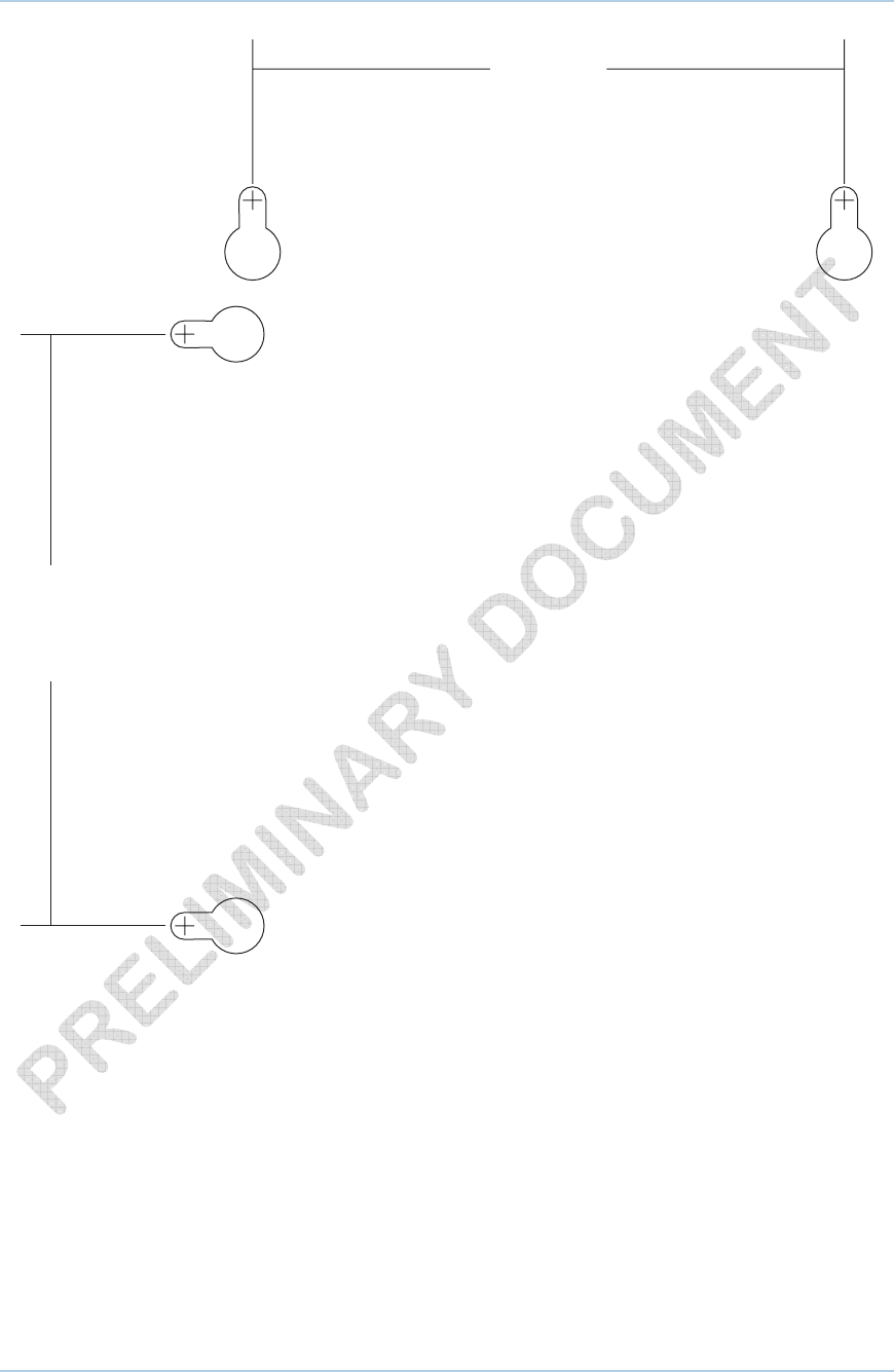
4.00"
(10.20 cm)
4.00"
(10.20 cm)
Figure 1 Wall Mounting Template
2 • Getting Started 24
This document is uncontrolled pending incorporation in a Motorola CMS
3 Basic Configuration
For more advanced configuration information, see Configuring TCP/IP and Setting Up
Your Wireless LAN.
For normal operation, you do not need to change most default settings. The following
caution statements summarize the issues you must be aware of:
CAUTION: To prevent unauthorized configuration, change the default
password immediately when you first configure the SVG1501. See
Changing the SVG1501 Default Password.
Firewalls are not foolproof. Choose the most secure firewall policy you
can. See the Firewall Pages.
Starting the SVG1501 Configuration Manager
(CMGR)
The SVG1501 Configuration Manager (CMGR) allows you to change and view the
settings on your SVG1501.
1. Open the web browser on a computer connected to the SVG1501 over an Ethernet
connection.
Note: Do not attempt to configure the SVG1501 over a wireless
connection.
2. In the Address or Location field of your browser, type http://192.168.0.1 and
press ENTER.
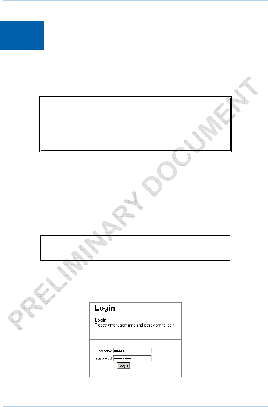
3. Type admin in the Username field (this field is case-sensitive).
4. Type motorola in the Password field (this field is case-sensitive).
5. Click Login to display the SVG1501 Status Connection page.
3 • Basic Configuration 25
This document is uncontrolled pending incorporation in a Motorola CMS
The Status Connection page provides the following status information on the network
connection of the SVG1501:
• RF Downstream Channel, which uses lower cable frequencies to transmit data
• RF Upstream Channel, which uses higher cable frequencies to receive data
Click the Refresh button in your web browser any time you want to refresh the
information on this page.
If you have any problems starting the SVG1501 Configuration Manager (CMGR), see
Troubleshooting for more information.
SVG1501 Menu Options Bar
The SVG1501 Menu Options bar is displayed along the top of the SVG1501 Configuration
Manager window. When a menu option is selected, a top-level page for that option is
displayed.
Configuration Manager Menu Options Bar
Menu Option Pages Function
Status Provides information about the SVG1501 hardware and software, MAC
address, digital voice modem IP address, serial number, and related
information. You can also monitor your cable system connection.
Additional pages provide diagnostic tools and allow you to change your
SVG1501 user name and password.
Wireless Configures and monitors SVG1501 wireless networking features
3 • Basic Configuration 26
This document is uncontrolled pending incorporation in a Motorola CMS
Menu Option Pages Function
Parental Control Configures and monitors the SVG1501 parental control feature
MTA Displays initialization status of the MTA
Logout Exits the SVG1501 Configuration Manager
CAUTION: To prevent unauthorized configuration, immediately change
the default password when you first configure your Motorola SVG1501.
SVG1501 Submenu Options
Additional features for each menu option are displayed by clicking a Submenu Option in
the left panel of each page. When selected, the submenu option will be highlighted in
yellow.
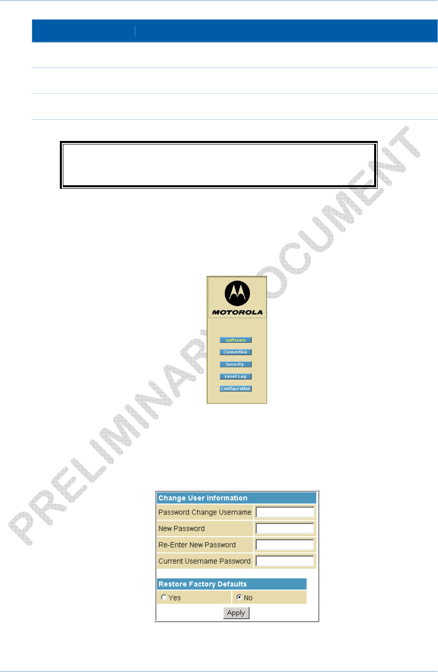
Changing the SVG1501 Default Password
Do the following to change the default password:
1. On the SVG1501 Status page, click the Security submenu option.
2. In the Password Change Username field, type your new User Name.
3 • Basic Configuration 27
This document is uncontrolled pending incorporation in a Motorola CMS
3. In the New Password field, type your new password (this field is case sensitive).
4. In the Re-Enter New Password field, type your new password again (this field is case
sensitive).
5. In the Current Username Password field, type your old password.
6. Click Apply to save your changes.
Restore Factory Defaults
To reset the user name and password back to the original factory settings:
1. Select Yes, and then click Apply.
2. You must login with the default user name, admin, and password, motorola, after
applying this change. All entries are case-sensitive.
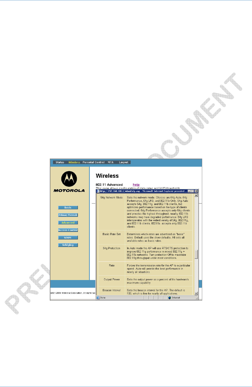
Getting Help
To retrieve help information for any menu option, click help on that page. See the
sample Wireless help page shown below:
You can use the Windows scroll bar to view additional items on the help screens.
Exiting the SVG1501 Configuration Manager
To logoff and close the SVG1501 Configuration Manager:
• Click Logout on the SVG1501 Menu Options bar.
3 • Basic Configuration 28
This document is uncontrolled pending incorporation in a Motorola CMS
4 Status Pages
The SVG1501 Status pages provide information about the SVG1501 hardware and
software, MAC address, cable modem IP address, serial number, and related
information. You can also monitor your cable system connection. Additional pages
provide diagnostic tools and allow you to change your SVG1501 user name and
password.
You can click any Status submenu option to view or change the status information for
that option.
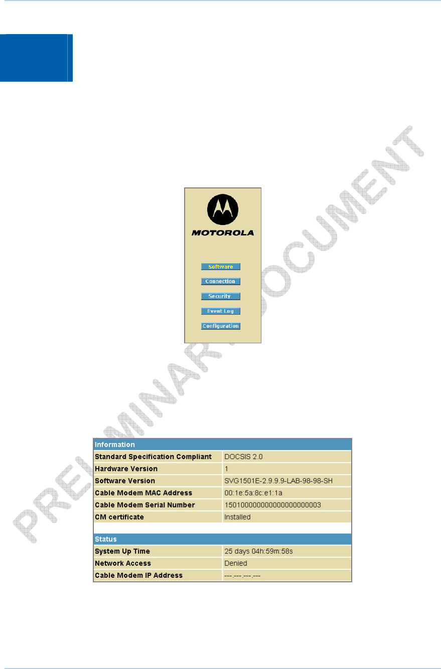
Status Software Page
This page displays information about the hardware version, software version, MAC
address, cable modem IP address, serial number, system “up” time, and network
registration status.
4 • Status Pages 29
This document is uncontrolled pending incorporation in a Motorola CMS
4 • Status Pages 30
This document is uncontrolled pending incorporation in a Motorola CMS
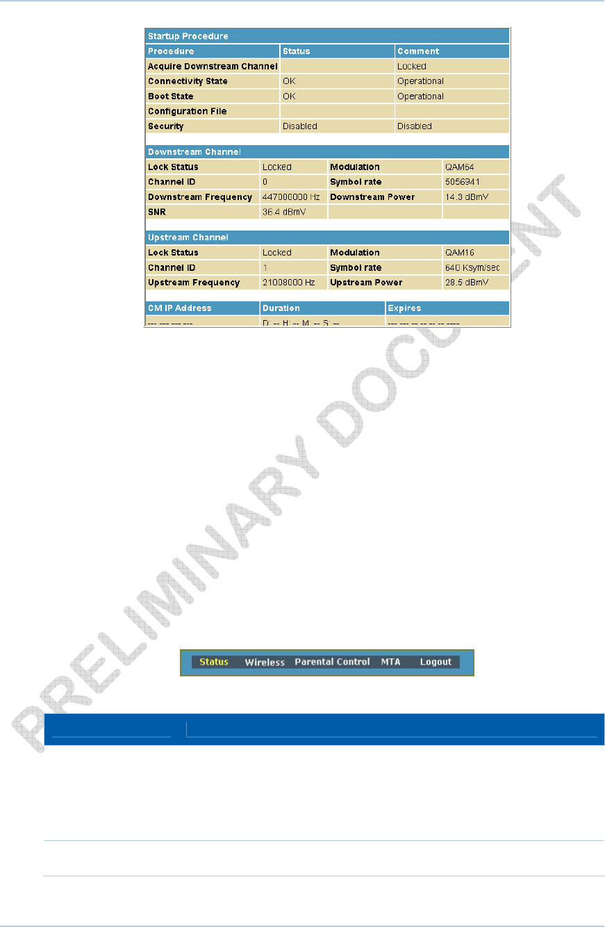
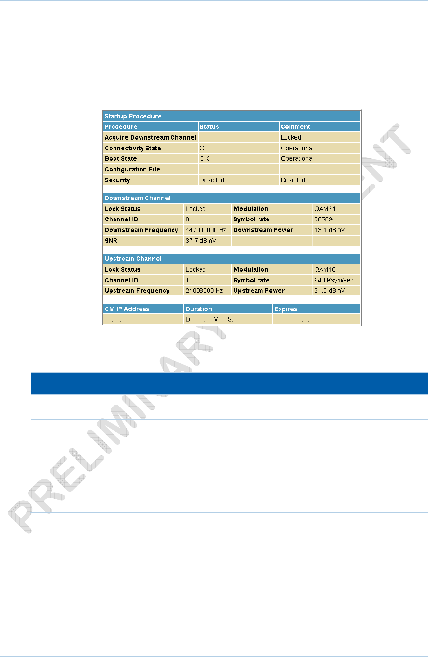
Status Connection Page
This page provides the HFC and IP network connectivity status of the SVG1501 cable
modem.
You can click the Refresh button in your web browser to refresh the information on this
page at any time.
Field Descriptions for the Status Connection Page
Field Description
Startup Procedure Startup status information about the cable modem.
Downstream Channel Status information about the RF downstream channels,
including downstream channel frequency and downstream
signal power and modulation.
Upstream Channel Status information about the RF upstream channels,
including upstream channel ID and upstream signal power
and modulation.
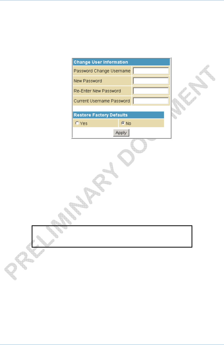
Status Security Page
This page allows you to define administrator access privileges by changing your
SVG1501 user name and password. It also allows you to reset your user name and
password to the default setting.
Changing the SVG1501 Default Password
1. In the Password Change Username field, type your new User Name.
2. In the New Password field, type your new password (this field is case-sensitive).
3. In the Re-Enter New Password field, type your new password again (this field is
case-sensitive).
4. In the Current Username Password field, type your old password.
5. Select Yes if you want to reset the user name and password to the original factory
settings.
6. Click Apply to update the user name password.
Note: You must login with the default user name, admin, and
password, motorola, after applying the restore factory settings change.
4 • Status Pages 31
This document is uncontrolled pending incorporation in a Motorola CMS
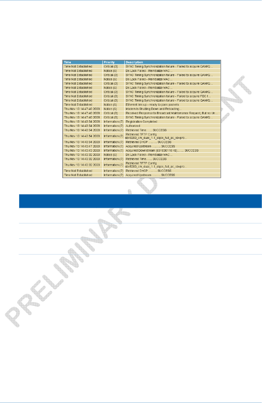
Status Event Log Page
This page lists the critical system events in chronological order. A sample SNMP Event
log is shown below:
Field Descriptions for the Status Event Log Page
Field Description
Time Indicates the date and time the error occurred
Priority Indicates the level of importance of the error
Description A brief definition of the error
4 • Status Pages 32
This document is uncontrolled pending incorporation in a Motorola CMS
5 Wireless Pages
The SVG1501 Wireless Pages allow you to configure your wireless LAN (WLAN).
You can click any Wireless submenu option to view or change the configuration
information for that option. WPA or WPA2 encryption provides higher security than WEP
encryption, but older wireless client cards may not support the newer WPA or WPA2
encryption methods.
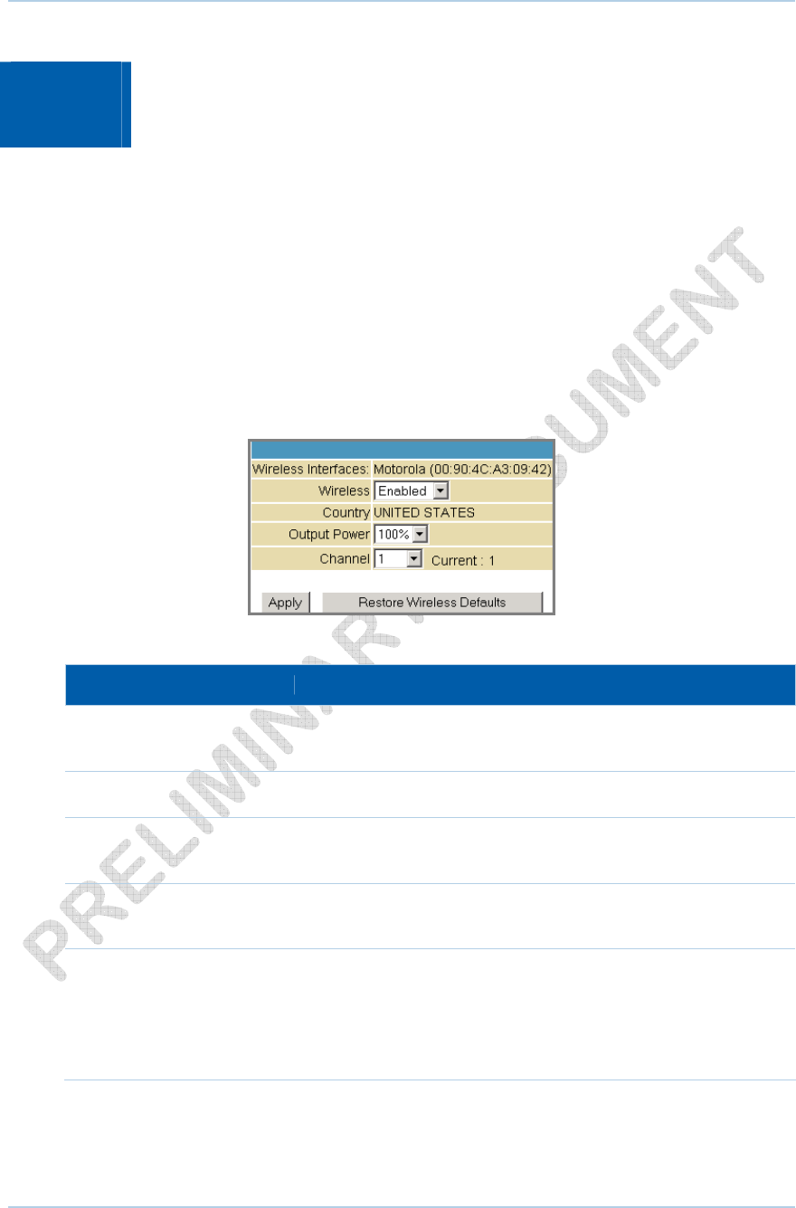
Wireless 802.11 Radio Page
This page allows you to configure the Wireless Radio parameters, including the current
country and channel number.
Field Descriptions for the Wireless 802.11 Radio Page
Field Description
Wireless Interfaces Shows the MAC address of the installed wireless card. It is not
configurable.
Wireless Shows if the wireless network is enabled or disabled
Country Restricts the channel set based on the country’s regulatory
requirements. This is a display-only field.
Output Power Sets a percentage of the output power of the hardware's
maximum capability.
Channel Selects the channel for access point (AP) operation. The list of
available channels depends on the designated country.
For this field, the channel selected on the wireless clients on
your WLAN must be the same as the one selected on the
SVG1501.
5 • Wireless Pages 33
This document is uncontrolled pending incorporation in a Motorola CMS
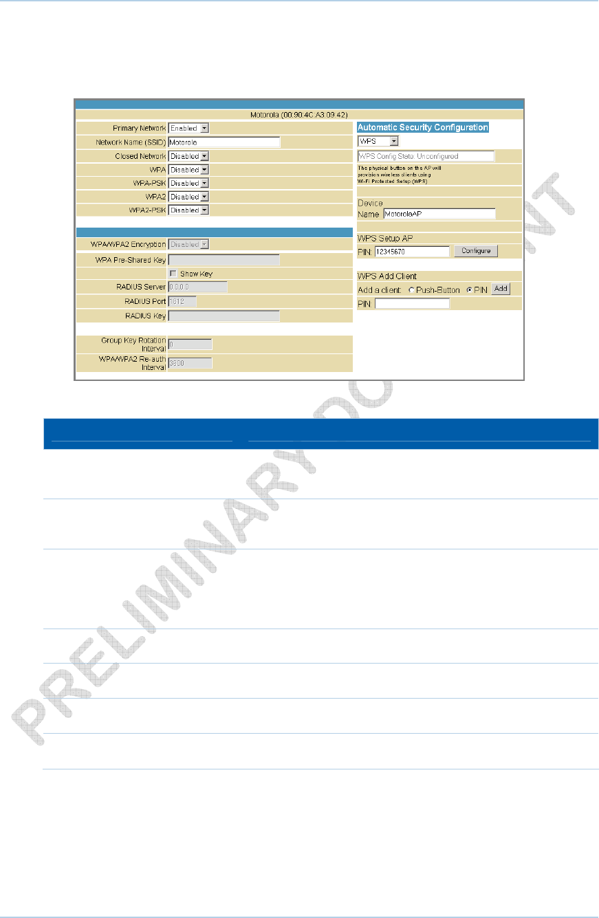
Wireless 802.11 Primary Network Page
This page allows you to configure the Primary wireless network.
Field Descriptions for the Wireless 802.11 Primary Network Page
Field Description
Primary Network When set to Enabled, beacon frames are transmitted with
the Primary Network SSID.
Network Name (SSID) Sets the Network Name (also known as SSID) of the Primary
wireless network. This is a 1-32 ASCII character string.
Closed Network With a closed network, users type the SSID into the client
application instead of selecting the SSID from a list. This
feature makes it slightly more difficult for the user to gain
access.
WPA Enables or disables Wi-Fi Protected Access encryption.
WPA-PSK Enables or disables a local WPA pre-shared key passphrase.
WPA2 Enables or disables Wi-Fi Protected Access 2 encryption.
WPA2-PSK Enables or disables a local WPA2 pre-shared key passphrase.
5 • Wireless Pages 34
This document is uncontrolled pending incorporation in a Motorola CMS

Field Description
WPA/WPA2 Encryption When using WPA or WPA2 authentication, these WPA
encryption modes can be set: TKIP, AES, or TKIP + AES. AES
(Advanced Encryption Standard) provides the strongest
encryption, while TKIP (Temporal Key Integrity Protocol)
provides strong encryption with improved compatibility. The
TKIP + AES mode allows both TKIP and AES-capable clients
to connect.
WPA Pre-Shared Key
Show Key
Sets the WPA Pre-Shared Key (PSK). This is either an 8-63
ASCII character string or a 64-digit hex number. This is
specified when the Network Authentication method is WPA-
PSK.
Show Key - When selected, the WPA Pre-Shared Key is
displayed.
RADIUS Server Sets the RADIUS server IP address to use for client
authentication using the dotted-decimal format
(xxx.xxx.xxx.xxx).
RADIUS Port Sets the UDP port number of the RADIUS server. The default
is 1812.
RADIUS Key Sets the shared secret for the RADIUS connection. The key is
a 0 to 255 character ASCII string.
Group Key Rotation Interval Sets the WPA Group Rekey Interval in seconds. Set to zero to
disable periodic rekeying.
WPA/WPA2 Re-auth Interval The re-authentication interval is the amount of time the
wireless router can wait before re-establishing authentication
with the CPE.
WEP Encryption WEP Encryption Enables or disables Wired Equivalent Privacy
encryption.
Shared Key Authentication The WEP protocol uses Shared Key Authentication, which is
an Authentication protocol where the CPE sends an
authentication request to the access point. Then the access
point sends a challenge text to the CPE.
The CPE uses either the 64-bit or 128-bit key to encrypt the
challenge text and sends the encrypted text to the access
point. The access point will decrypt the encrypted text and
then compare the decrypted message with the original
challenge text. If they are the same, the access point will let
the CPE connect; if it doesn’t match, then the access point
does not let the CPE connect.
5 • Wireless Pages 35
This document is uncontrolled pending incorporation in a Motorola CMS
Field Description
802.1x Authentication This is another type of authentication and is used on top of
WEP. 802.1x Authentication is a much stronger type of
authentication than WEP.
Network Key 1 – 4 Sets the static WEP keys when WEP encryption is enabled.
• Enter five ASCII characters or 10 hexadecimal digits for a
64-bit key.
• Enter 13 ASCII characters or 26 hexadecimal digits for a
128-bit key.
When both WPA encryption and WEP encryption are enabled,
only keys 2 and 3 are available for WEP encryption.
Current Network Key Selects the encryption (transmit) key when WEP encryption is
enabled.
PassPhrase PassPhrase Sets the text to use for WEP key generation.
5 • Wireless Pages 36
This document is uncontrolled pending incorporation in a Motorola CMS
5 • Wireless Pages 37
This document is uncontrolled pending incorporation in a Motorola CMS
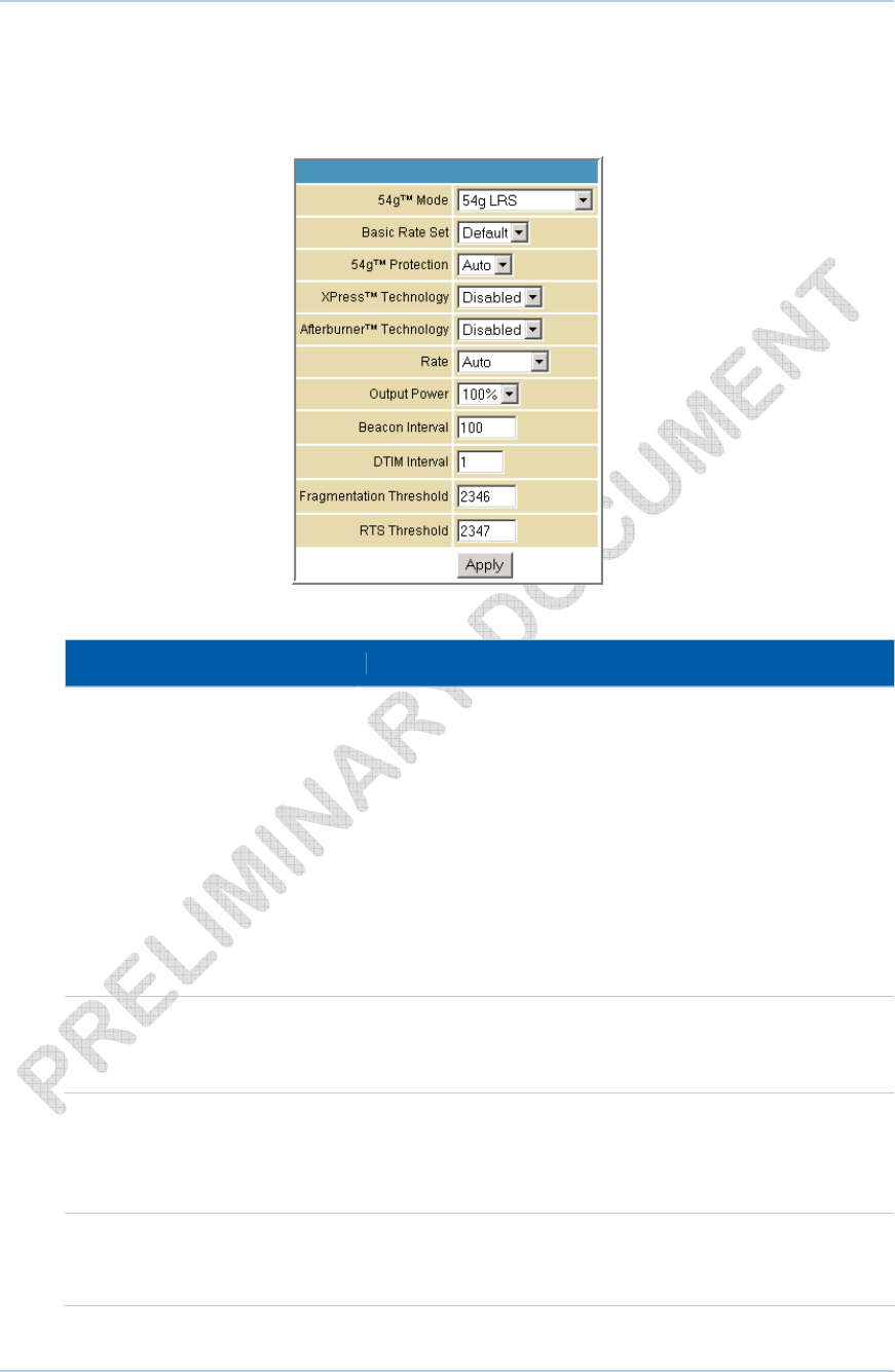
Wireless 802.11 Advanced Page
This page allows you to configure data rates and Wi-Fi thresholds.
Field Descriptions for the Wireless 802.11 Advanced Page
Field Description
54g™ Mode Sets these network modes:
54g Auto
54g Performance
54g LRS
802.11b only
54g Auto accepts 54g, 802.11g, and 802.11b clients, but
optimizes performance based on the type of connected
clients. 54g Performance accepts only 54g clients and
provides the highest performance throughout; nearby 802.11b
networks may have degraded performance. 54g LRS
interoperates with the widest variety of 54g, 802.11g, and
802.11b clients. 802.11b accepts only 802.11b clients.
Basic Rate Set Determines which rates are advertised as “basic” rates.
Default uses the driver defaults. All sets all available rates as
basic rates.
54g™ Protection In Auto mode, the AP will use RTS/CTS protection to improve
802.11g performance in mixed 802.11g + 802.11b networks.
Turn protection off to maximize 802.11g throughput under
most conditions.
XPress™ Technology This is a performance-enhancing Wi-Fi technology designed
for increasing throughput and efficiency. It is used when there
are mixed wireless networks in the surrounding area from
5 • Wireless Pages 38
This document is uncontrolled pending incorporation in a Motorola CMS
Field Description
802.11a/b/g networks.
Afterburner™ Technology This is also a performance-enhancing Wi-Fi technology that
enhances the existing 802.11g standard by increasing
throughput by 40 percent.
Rate Forces the transmission rate for the AP to a particular speed.
Auto will provide the best performance in nearly all situations.
Output Power Sets the output power as a percentage of the hardware’s
maximum capability.
Beacon Interval Sets the beacon interval for the AP. The default is 100, which
is fine for nearly all applications.
DTIM Interval Sets the wakeup interval for clients in power save mode.
When a client is running in power save mode, lower SVG1501
bin values provide higher performance but result in decreased
client battery life, while higher values provide lower
performance but result in increased client battery life.
Fragmentation Threshold Sets the fragmentation threshold. Packets exceeding this
threshold will be fragmented into packets no larger than the
threshold before packet transmission.
RTS Threshold Sets the RTS threshold. Packets exceeding this threshold will
cause the AP to perform an RTS/CTS exchange to reserve the
wireless medium before packet transmission.
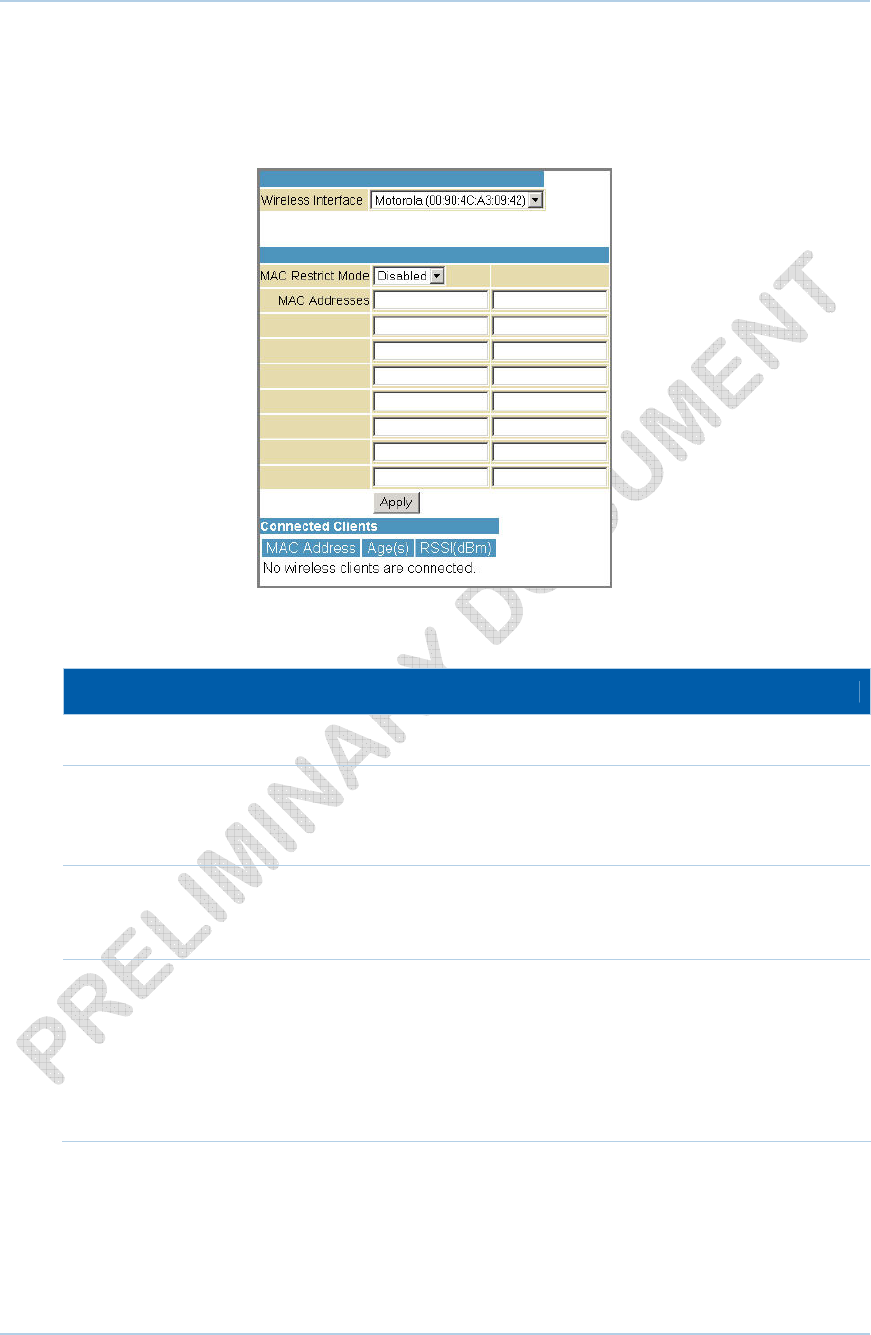
Wireless 802.11 Access Control Page
This page allows you to configure the Access Control to the AP as well as status on the
connected clients.
Field Descriptions for the Wireless 802.11 Access Control Page
Field Description
Wireless Interface
MAC Restrict Mode Selects whether wireless clients with the specified MAC
address are allowed or denied wireless access.
Select Disabled to allow all clients.
MAC Address A list of wireless client MAC addresses to allow or deny based
on the Restrict Mode setting. Valid input MAC address formats
are XX:XX:XX:XX:XX:XX and XX-XX-XX-XX-XX-XX.
Connected Clients A list of connected wireless clients. When a client connects
(associates) to the network, it is added to the list; when a client
leaves (disassociates) from the network, it is removed from the
list. For each client, the age (in seconds), estimated average
receive signal strength (in dBm), IP address, and host name are
presented. The age is the amount of time elapsed since data
was transmitted to or received from the client.
5 • Wireless Pages 39
This document is uncontrolled pending incorporation in a Motorola CMS
5 • Wireless Pages 40
This document is uncontrolled pending incorporation in a Motorola CMS
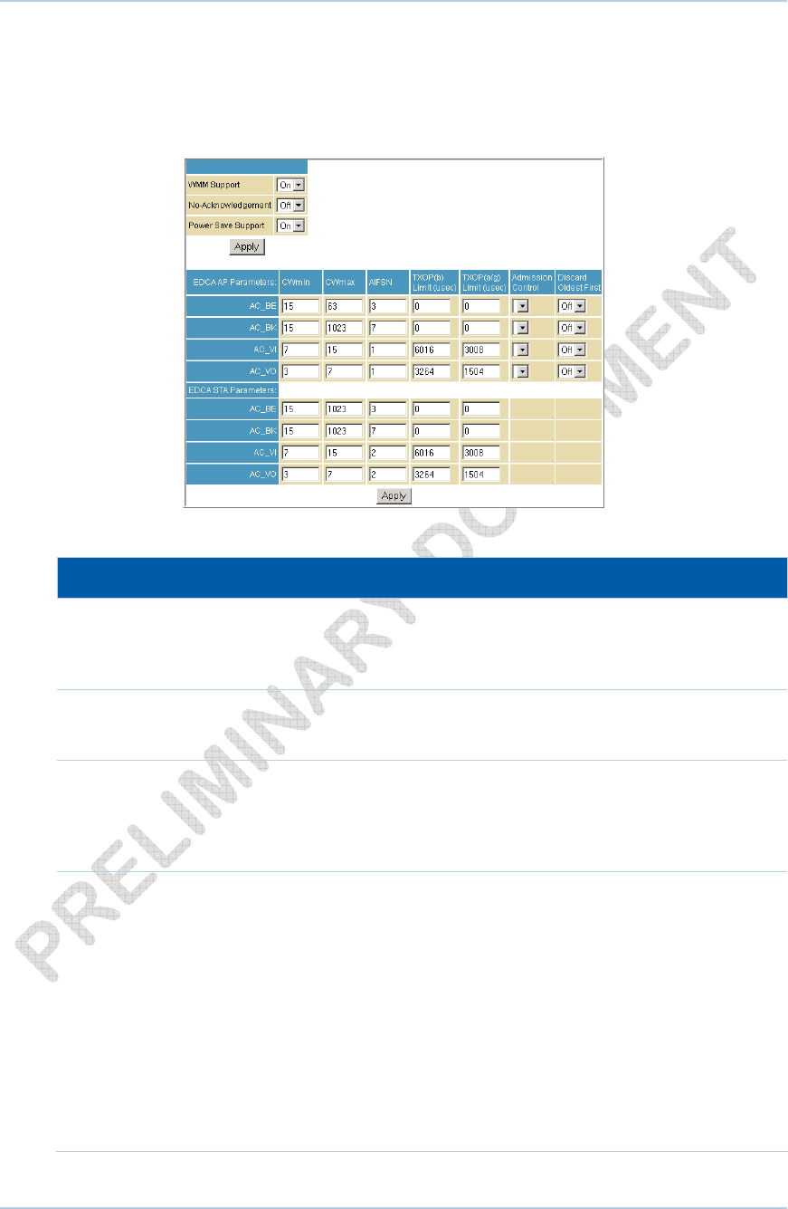
Wireless 802.11 Wi-Fi Multimedia Page
This page allows you to configure the Wi-Fi Multimedia Quality of Service (QoS).
Field Descriptions for the Wireless 802.11 Wi-Fi Multimedia Page
Field Description
WMM Support Sets WMM support to Auto, On, or Off.
If enabled (Auto or On), the WME Information Element is
included in beacon frame.
No-Acknowledgement Sets No-Acknowledgement support to On or Off.
When enabled, acknowledgments for data are not transmitted.
Power Save Support Sets Power Save support to On or Off.
When Power Save is enabled, the AP queues packets for STAs
that are in power-save mode. Queued packets are transmitted
when the STA notifies AP that it has left power-save mode.
EDCA AP Parameters Specifies the transmit parameters for traffic transmitted from
the AP to the STA in four Access Categories:
Best Effort (AC_BE), Background (AC_BK), Video (AC_VI), and
Voice (AC_VO)
Transmit parameters include Contention Window (CWmin and
CWmax), Arbitration Inter Frame Spacing Number (AIFSN), and
Transmit Opportunity Limit (TXOP Limit).
There are also two AP-specific settings: Admission Control and
Discard Oldest First. Admission control specifies if admission
control is enforced for the Access Categories. Discard Oldest
First specifies the discard policy for the queues. On discards
the oldest first; Off discards the newest first.
Field Description
EDCA STA Parameters Specifies the transmit parameters for traffic transmitted from
the STA to the AP in four Access Categories:
Best Effort (AC_BE), Background (AC_BK), Video (AC_VI), and
Voice (AC_VO)
Transmit parameters include Contention Window (CWmin and
CWmax), Arbitration Inter Frame Spacing Number (AIFSN), and
Transmit Opportunity Limit (TXOP Limit).
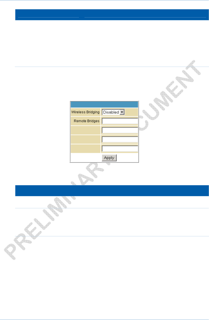
Wireless 802.11 Bridging Page
This page allows you to configure the WDS features.
Field Descriptions for the Wireless 802.11 Bridging Page
Field Description
Wireless Bridging Enables or disables wireless bridging.
Remote Bridges Table of remote bridge MAC addresses authorized to establish a
wireless bridge. Up to four remote bridges may be connected.
Typically, you will also have to enter your AP’s MAC address on
the remote bridge.
5 • Wireless Pages 41
This document is uncontrolled pending incorporation in a Motorola CMS
Setting Up Your Wireless LAN
You can use the SVG1501 as an access point for a wireless LAN (WLAN) without
changing its default settings.
CAUTION: To prevent unauthorized eavesdropping or access to WLAN
data, you must enable wireless security. The default SVG1501 settings
provide no wireless security. After your WLAN is operational, be sure to
enable wireless security
To enable security for your WLAN, you can do the following on the SVG1501:
• Encrypt wireless LAN transmissions
• Restrict wireless LAN access to further prevent unauthorized WLAN intrusions using
the Wireless 802.11 Access Control Page
CAUTION: Never provide your SSID, WPA or WEP passphrase, or WEP
key to anyone who is not authorized to use your WLAN.
Connect at least one computer to the SVG1501 Ethernet port to perform configuration.
Do not attempt to configure the SVG1501 over a wireless connection.
You need to configure each wireless client (station) to access the SVG1501 LAN as
described in Installing Wireless Clients.
Another step to improve wireless security is to place wireless components away from
windows. This decreases the signal strength outside the intended area.
Encrypting Wireless LAN Transmissions
To prevent unauthorized viewing of data transmitted over your WLAN, you must encrypt
your wireless transmissions. Choose one of:
Encrypting Wireless LAN Transmissions
Configure on the SVG1501 Required on Each Wireless Client
If all of your wireless clients
support Wi-Fi Protected Access
(WPA), Motorola recommends
configuring WPA on the SVG1501
If you use a local pre-shared key (WPA-PSK)
passphrase, you must configure the identical
passphrase to the SVG1501 on each wireless client.
Home and small-office settings typically use a local
passphrase.
Otherwise, configure WEP on the
SVG1501
You must configure the identical WEP key to the
SVG1501 on each wireless client.
5 • Wireless Pages 42
This document is uncontrolled pending incorporation in a Motorola CMS
If all of your wireless clients support WPA encryption, Motorola recommends using WPA
instead of WEP because WPA:
• Provides much stronger encryption and is more secure
• Provides authentication to ensure that only authorized users can log in to your WLAN
• Is much easier to configure
• Uses a standard algorithm on all compliant products to generate a key from a textual
passphrase
• Will be incorporated into the new IEEE 802.11i wireless networking standard
For new wireless LANs, Motorola recommends purchasing client adapters that support
WPA encryption.
Installing Wireless Clients
Note: Use the SVG1501 Installation CD-ROM to set your clients
security. The passcode is located on the modem label.
For each wireless client computer (station), install the wireless adapter by following the
instructions supplied with the adapter. Be sure to:
1. Insert the CD-ROM for the adapter in the CD-ROM drive on the client.
2. Install the device software from the CD.
3. Insert the adapter in the PCMCIA or PCI slot or connect it to the USB port.
4. Configure the adapter to obtain an IP address automatically.
On a PC with Wireless Client Manager installed, the icon is displayed on the
Windows task bar. Double-click the icon to launch the utility. You may need to do the
following to use a wireless client computer to access the Internet:
Configuring Wireless Clients
If You Performed: On Each Client, You Need to Perform:
Configuring WPA on the SVG1501 Configuring a Wireless Client for WPA or WPA2
Configuring WEP on the SVG1501 Configuring a Wireless Client for WEP
Configuring the Wireless Network
Name on the SVG1501
Configuring a Wireless Client with the Network Name
(SSID)
Configuring a MAC Access Control
List on the SVG1501
No configuration on client required
5 • Wireless Pages 43
This document is uncontrolled pending incorporation in a Motorola CMS
5 • Wireless Pages 44
This document is uncontrolled pending incorporation in a Motorola CMS
Installing a Wireless Client for WPA
If you enabled WPA and set a PSK Passphrase by configuring WPA on the SVG1501, you
must configure the same passphrase (key) on each wireless client. The SVG1501 cannot
authenticate a client if:
• WPA is enabled on the SVG1501 but not on the client
• The client passphrase does not match the SVG1501 PSK Passphrase
CAUTION: Never provide the PSK Passphrase to anyone who is not
authorized to use your WLAN.
Configuring a Wireless Client for WEP
If you enabled WEP and set a key by configuring WEP on the SVG1501, you must
configure the same WEP key on each wireless client. The SVG1501 cannot authenticate
a client if:
• Shared Key Authentication is enabled on the SVG1501 but not on the client
• The client WEP key does not match the SVG1501 WEP key
For all wireless adapters, you must enter the 64-bit or 128-bit WEP key generated by the
SVG1501.
CAUTION: Never provide the WEP key to anyone who is not authorized
to use your WLAN.
Configuring a Wireless Client with the Network Name
(SSID)
After you specify the network name on the Wireless Basic Page, many wireless cards or
adapters automatically scan for an access point, such as the SVG1501 and the proper
channel and data rate. If your card requires you to manually start scanning for an access
point, do so following the instructions in the documentation supplied with the card. You
must enter the same SSID in the wireless configuration setup for the device to
communicate with the SVG1501.
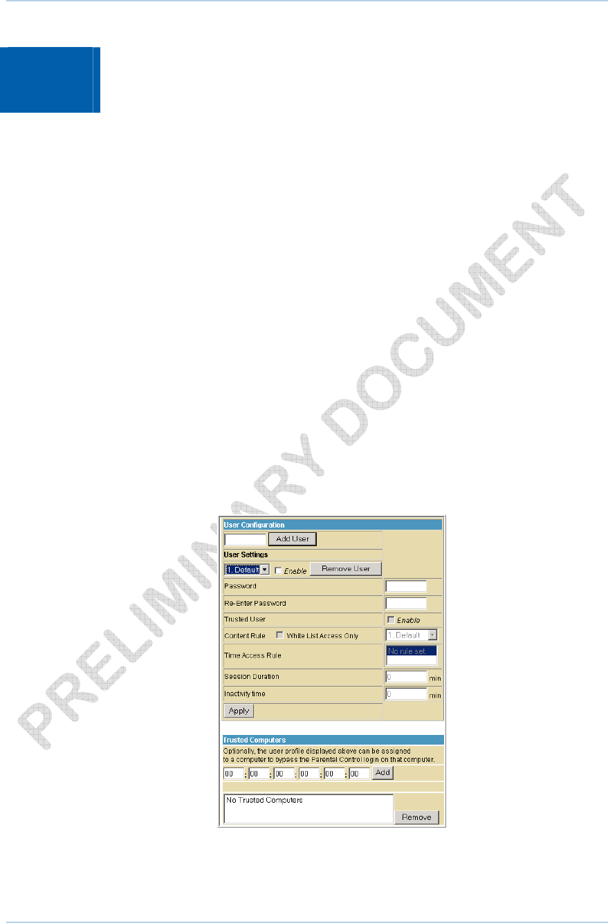
6 Parental Control Pages
The SVG1501 Parental Control Pages allow you to configure access restrictions to a
specific device connected to the SVG1501 LAN.
You can click any Parental Control submenu option to view or change the
configuration information for that option.
Parental Control User Setup Page
This page is the master page. Each user is linked to a specified time access rule, content
filtering rule, and login password to get to the filtered content. You may also specify a
user as a “trusted user,” which means that person will have access to all Internet
content regardless of the filters that you define. You can use the Trusted User checkbox
as a simple override to grant a user full access, while storing all of the filtering settings
for easy availability.
You can also enable Internet session duration timers, which set a limited amount of time
for Internet access from the rules you select. The user must enter their password only
the first time to access the Internet. It is not necessary to enter the password each time
a new web page is accessed. In addition, there is a password inactivity timer. If there is
no Internet access for the specified time in minutes, the user must login again. These
timed logins ensure that a specific user uses the Internet gateway appropriately.
6 • Parental Control Pages 45
This document is uncontrolled pending incorporation in a Motorola CMS
6 • Parental Control Pages 46
This document is uncontrolled pending incorporation in a Motorola CMS
Field Descriptions for the Parental Control User Setup Page
Field Description
Add User Button Adds a user to set the parental controls for a specific user.
User Settings Select the user for whom you want to modify access
restrictions.
Checkmark Enable to select the user.
Click Remove User to delete the user from Parental Controls.
Password Enter a user password to log onto the Internet.
Re-Enter Password Enter the password again for confirmation.
Trusted User The selected user will have full access to Internet content, thus
overriding any set filters.
Checkmark Enable to override set filters without having to turn
off filter settings.
Content Rule Used to specify which websites a selected user is allowed to
access.
Check White List Access Only and choose a user from the
drop-down list.
Time Access Rule You can choose a rule that restricts when a selected user can
use the Internet.
Session Duration You can set the amount of time a selected user can use the
Internet.
Inactivity time You can set the amount of inactivity time before the Internet
automatically closes for a selected user.
Trusted Computers You can enter a selected user’s CPE MAC address so that CPE
can access the Internet without being censored by the Parental
Control.
When done entering the MAC address, click Add.
When done, click Apply to activate and save any changes you made.
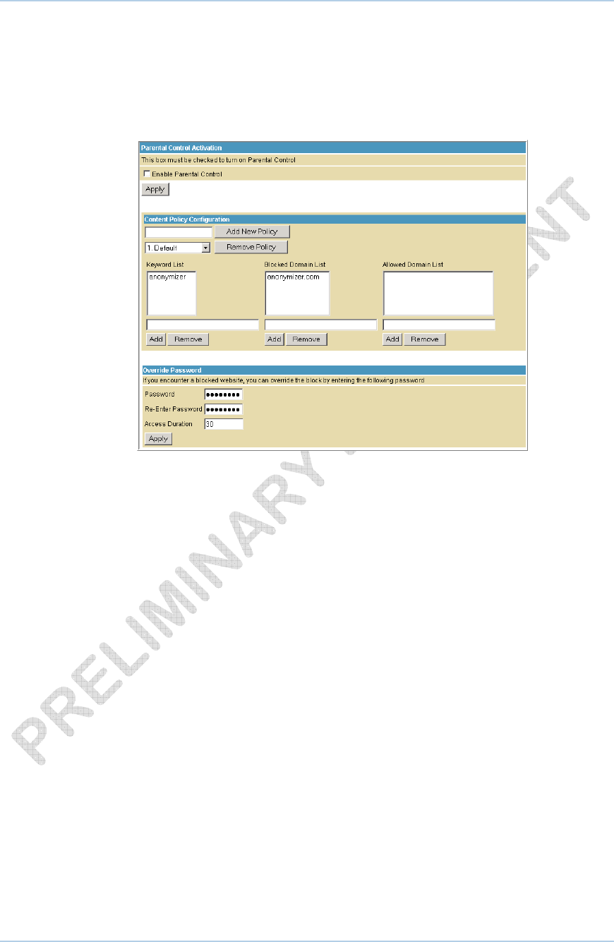
Parental Control Basic Setup Page
This page allows you to set rules to block certain kinds of Internet content and certain
Web sites.
After you have changed your Parental Control settings, click the appropriate Apply, Add,
or Remove button.
Click Refresh in your web browser window to view your current settings.
6 • Parental Control Pages 47
This document is uncontrolled pending incorporation in a Motorola CMS
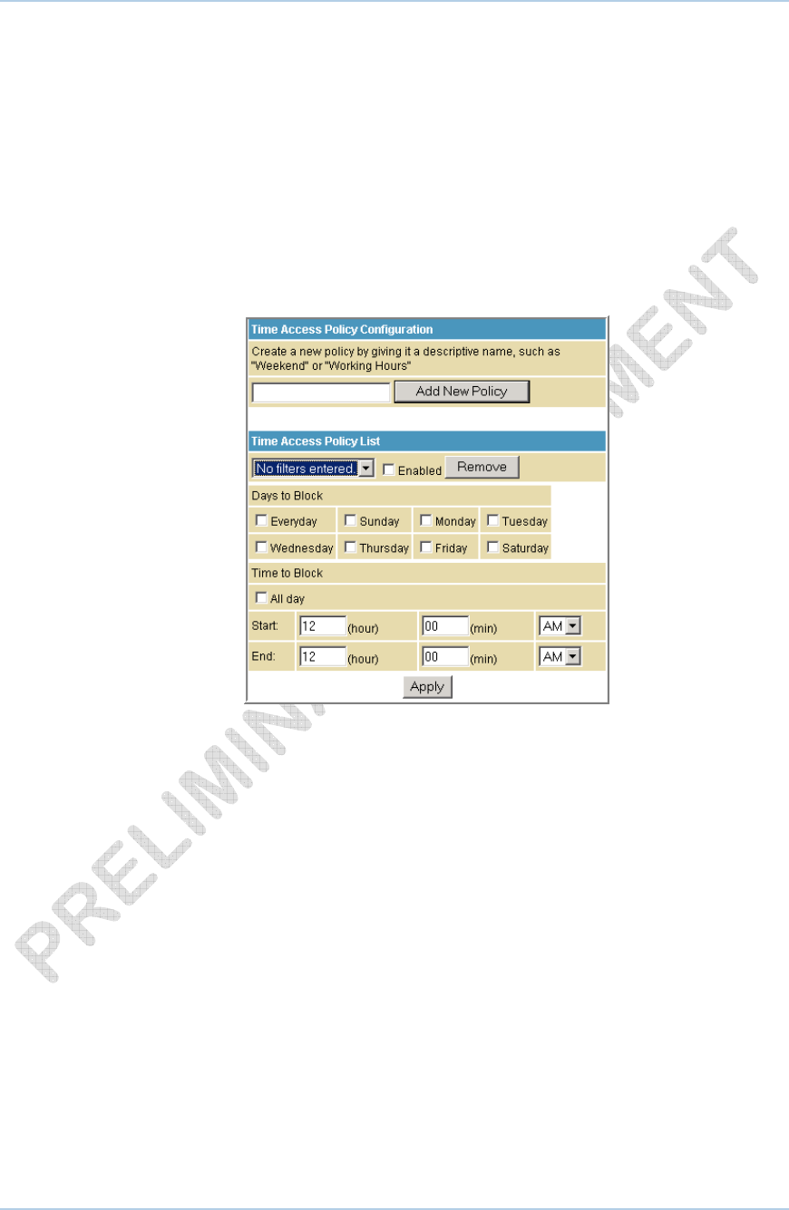
6 • Parental Control Pages 48
This document is uncontrolled pending incorporation in a Motorola CMS
Parental Control Time of Day Filter Page
This page allows you to block all Internet traffic to and from specified devices on your
SVG1501 network based on the day and time settings you specify. You can set policies
to block Internet traffic for the entire day or just certain time periods within each day for
specific users. You can add up to 30 eight-character categories (filter names) with
different day and time settings. You enter a name for each time filter in the Add New
Policy field. Any time filter for Internet access can be enabled or disabled at any time.
The time filters for limited Internet access are applied for each user in the Time Access
Rule field on the Parental Control User Setup Page.
Once each category change has been made, the user must click Apply at the bottom of
the page to store and activate the settings. These same category names for blocking
profiles show up in the Parental Control section on the User Setup page in the “Time
Access Rules” section. On that page, each user can be assigned up to four of these
categories simultaneously.
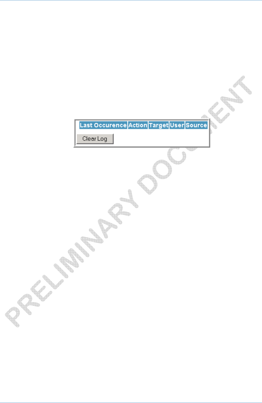
Parental Control Local Log Page
This page displays the Parental Control local log report. The event log is a running list of
the last 30 Parental Control access violations, which include the following items on
Internet traffic:
• If the user’s Internet access is blocked (time filter)
• If a blocked keyword is detected in the URL
• If a blocked domain is detected in the URL
• If the online lookup service detects that the URL falls under a blocked category
6 • Parental Control Pages 49
This document is uncontrolled pending incorporation in a Motorola CMS
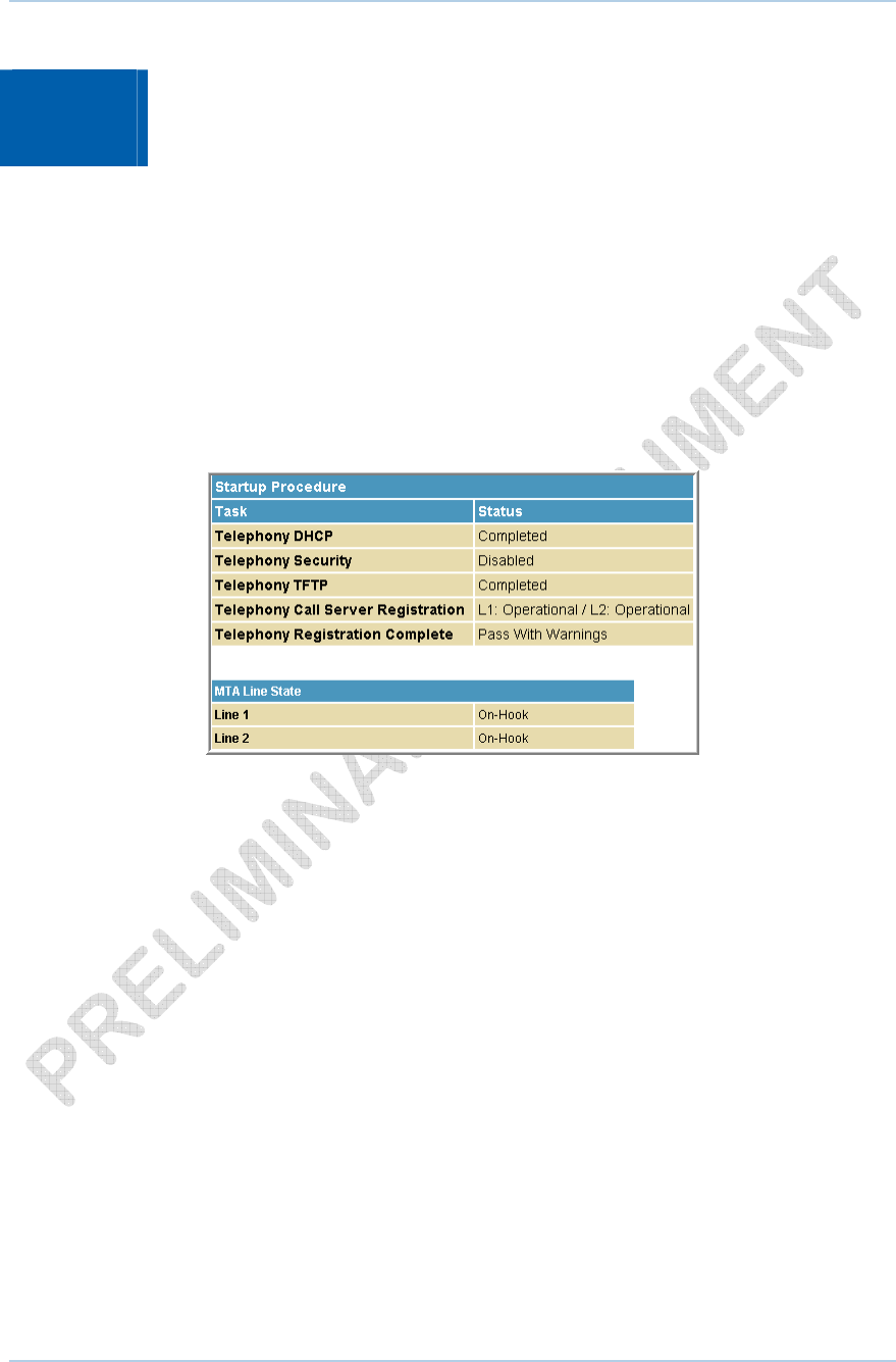
7 MTA Pages
The Multimedia Terminal Adapter (MTA) in your SVG1501 provides digital voice-over-IP
(VoIP) services, which allow you to use the Internet to make telephone calls. Basic
telephone functions, such as call waiting, three-way calling, voice mail, and fax
transmissions, are supported with this connection on the SVG1501.
You can click any MTA submenu option to view the status information for that option.
MTA Status Page
This page displays the initialization status of the MTA.
7 • MTA Pages 50
This document is uncontrolled pending incorporation in a Motorola CMS
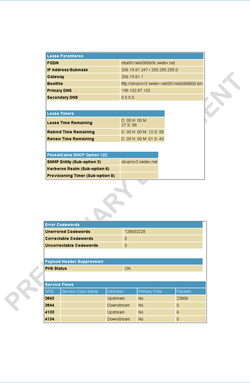
MTA DHCP Page
This page displays the MTA DHCP lease information.
MTA QoS Page
This page displays the MTA Quality of Service (QoS) parameters.
7 • MTA Pages 51
This document is uncontrolled pending incorporation in a Motorola CMS
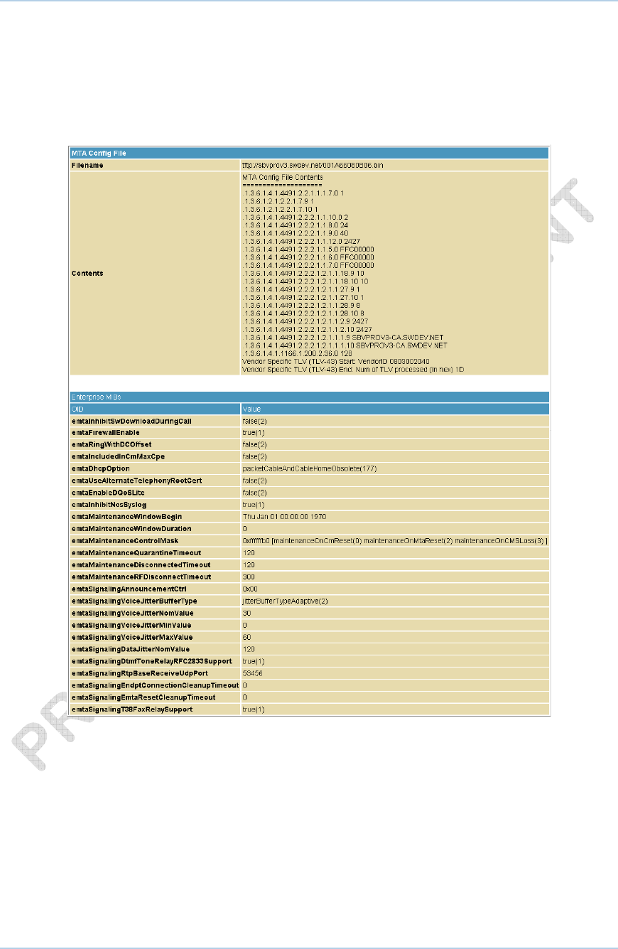
MTA Provisioning Page
This page displays the MTA provisioning details about your SVG1501 VoIP telephone
connection.
7 • MTA Pages 52
This document is uncontrolled pending incorporation in a Motorola CMS
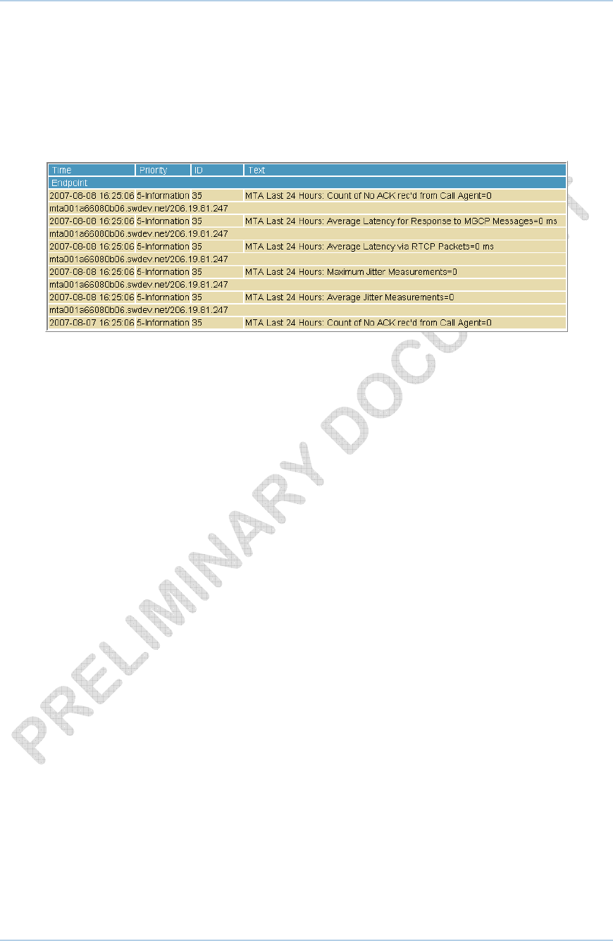
MTA Event Log
This page displays the MTA Event Log information related to your SVG1501 VoIP
telephone connection. It shows Diagnostic messages generated by the MTA. This
information is intended for use by a qualified technician.
7 • MTA Pages 53
This document is uncontrolled pending incorporation in a Motorola CMS
8 Troubleshooting
If the solutions listed here do not solve your problem, contact your service provider.
Before calling your service provider, try pressing the Reset button on the rear panel of
the SVG1501. Resetting the SVG1501 may take five to 30 minutes. Your service provider
may ask for the status of the lights as described in Front-Panel LEDs and Error
Conditions.
Solutions
Table 1 – Troubleshooting Solutions
Problem Possible Solution
Power light is off Check that the SVG1501 is properly plugged into the electrical outlet.
Check that the electrical outlet is working.
Press the Reset button.
Cannot send or
receive data
On the front panel, note the status of the LEDs and refer to Front-
Panel LEDs and Error Conditions to identify the error. If you have
cable TV, check that the TV is working and the picture is clear. If you
cannot receive regular TV channels, the data service will not function.
Check the coaxial cable at the SVG1501 and wall outlet. Hand-tighten
if necessary.
Check the IP address. Follow the steps for verifying the IP address
for your system described in Configuring TCP/IP. Call your service
provider if you need an IP address.
Check that the Ethernet cable is properly connected to the SVG1501
and the computer.
If a device is connected via the Ethernet port, verify connectivity by
checking the LINK LEDs on the rear panel.
8 • Troubleshooting 54
This document is uncontrolled pending incorporation in a Motorola CMS
Problem Possible Solution
Wireless client(s)
cannot send or receive
data
Perform the first four checks in “Cannot send or receive data.”
Check the Security Mode setting on the Wireless Primary Network
Page:
• If you enabled WPA and configured a passphrase on the SVG1501,
be sure each affected wireless client has the identical passphrase.
If this does not solve the problem, check whether the wireless
client supports WPA.
• If you enabled WEP and configured a key on the SVG1501, be sure
each affected wireless client has the identical WEP key. If this
does not solve the problem, check whether the client’s wireless
adapter supports the type of WEP key configured on the SVG1501.
• To temporarily eliminate the Security Mode as a potential issue,
disable security.
After resolving your problem, be sure to re-enable wireless security.
• On the Wireless Access Control Page, be sure the MAC address
for each affected wireless client is correctly listed.
Slow wireless
transmission speed
with WPA enabled
On the Wireless Primary Network Page, check whether the WPA
Encryption type is TKIP. If all of your wireless clients support AES,
change the WPA Encryption to AES.
Front-Panel LEDs and Error Conditions
The SVG1501 front panel LEDs provide status information for the following error
conditions:
Table 2 – Front-Panel LEDs and Error Conditions
LED Status If, During Startup: If, During Normal Operation:
POWER OFF SVG1501 is not properly plugged
into the power outlet
The SVG1501 is unplugged
RECEIVE FLASHING Downstream receive channel
cannot be acquired
The downstream channel is lost
SEND FLASHING Upstream send channel cannot be
acquired
The upstream channel is lost
ONLINE FLASHING IP registration is unsuccessful The IP registration is lost
8 • Troubleshooting 55
This document is uncontrolled pending incorporation in a Motorola CMS

A • Product Specifications 56
This document is uncontrolled pending incorporation in a Motorola CMS
A Product Specifications
All features, functionality, and other product specifications are subject to change without
notice or obligation.
Certain features may not be activated by your service provider and/or their network
settings may limit the feature’s functionality. Additionally, certain features may require a
subscription. Contact your service provider for details. All features, functionality, and
other product specifications are subject to change without notice or obligation.
GENERAL
Standards
Cable Interface
Network Interface
Wireless Interface
Dimensions
Interoperates with DOCSIS
F-connector, female, 75 Ω
Four 10/100 Ethernet ports
802.11b/g Wi-Fi
7.3 in H x 1.5 in W x 6.1 in D
(18.68 cm x 3.81 cm x 15.49 cm)
INPUT POWER
North America
Outside North America
105 to 125 VAC, 60 Hz
100 to 240 VAC, 50 to 60 Hz
ENVIRONMENT
Operating Temperature
Storage Temperature
Operating Humidity
32° F to 104° F (0° C to 40° C)
–22° F to 158° F (–30° C to 70° C)
5 to 95% R.H. (non-condensing)
DOWNSTREAM
Modulation
Maximum Data Rate*
Bandwidth
Symbol Rates
Operating Level Range
Frequency Range
Input Impedance
64 or 256 QAM
38 Mbps (256 QAM at 5.361 Msym/s)
6 MHz
64 QAM @ 5.069 Msym/s, 256 QAM @ 5.361 Msym/s
–15 to 15 dBmV
88 to 860 MHz
75 Ω (nominal)
*When comparing download speeds with a traditional 28.8k analog modem. Actual speeds will
vary and are often less than the maximum possible. Several factors affect upload and download
speeds, including, but not limited to, network traffic and services offered by your cable operator
or broadband service provider, computer equipment, type of service, number of connections to
server, and availability of Internet route(s).

A • Product Specifications 57
This document is uncontrolled pending incorporation in a Motorola CMS
UPSTREAM
Modulation
Maximum Channel Rate
Bandwidth
Symbol Rates
Operating Level Range
A-TDMA
S-CDMA
Output Impedance
Frequency Range
8***, 16, 32***, 64***,128*** QAM or QPSK
30 Mbps**
200 kHz, 400 kHz, 800 kHz, 1.6 MHz, 3.2 MHz, 6.4 MHz***
160, 320, 640, 1280, 2560, 5120*** ksym/s
8 to 54 dBmV (32, 64 QAM),
8 to 55 dBmV (8, 16 QAM) ,
8 to 58 dBmV (QPSK)
8 to 53 dBmV (all modulations)
75 Ω (nominal)
5 to 42 MHz (edge to edge)
5-65 for Euro-DOCSIS
TELEPHONY
Line Type
Hook State Signaling
Maximum Line Length
(one-way)
DTMF Level Sensitivity
Range
Speech Coding
Line Termination
Loss Plan
Receive
Transmit
Loss Plan Tolerance
Ringing Wave Form
Ringing Crest Factor
2-wire
Loop start
500 ft (AWG 26/0.4 mm @ 65 °C)
0 and –20 dBm
64 kbps PCM, μ-law or A-law companding; support for G.711,
G.726, G.728, G.729, G.723.1, iLBC, and BV16/32 codecs
Configurable based on market needs
(D/A) 4 Db
(A/D) 2 dB (configurable based on market needs)
±1 dB; 60/50 Hz loss >20 dB (one-way) (referenced to off-hook
loss at 1,004 Hz)
Quasi-trapezoidal
1.2 <CF <1.6
**Actual data throughput will be less due to physical layer overhead (error correction coding,
burst preamble, and guard interval).
***With A-TDMA or S-CDMA enabled Digital voice modem Termination System (CMTS).
NETWORK
Gateway
Wireless LAN
Power Management
802.11i Security
Mobile Pairing
DHCP, NAT; static routing and dynamic IP routing (RIPv1, RIPv2);
SPI firewall with DoS protection and intrusion prevention; port,
packet, and URL keyword filtering; full suite of ALGs; UPnP IGD
1.0
802.11b/g Wi-Fi, two internal antennas, WDS bridging, 802.11e
WMM admission control, QoS
802.11e WMM power save/U-APSD (Unscheduled-Automatic
Power Save Delivery)
WEP-64/128, WPA-PSK, WPA, WPA2, TKIP, AES, 802.1x, 802.11i
(pre-authentication)
User-friendly Wi-Fi–protected setup (WPS) for secure mobile

A • Product Specifications 58
This document is uncontrolled pending incorporation in a Motorola CMS
Regulatory Domains
Transmit Power Output
IEEE 802.11b
IEEE 802.11g
Receiver Sensitivity
pairing with compatible dual-mode handset
To include US, Canada, ETSI, World
19 dBm +1/–1.5 dB at all rates in all channels
16 dBm +1/–1 dB at 54 Mbps in all channels
> –90 dBm at 11 Mbps;
> –74 dBm at 54 Mbps
B • Glossary 59
This document is uncontrolled pending incorporation in a Motorola CMS
B Glossary
This glossary defines some of the terms and acronyms used in this document.
TERM DEFINITION
Authentication A process where the CMTS verifies that access is authorized, using a
password, trusted IP address, or serial number.
coaxial cable A type of cable consisting of a center wire surrounded by insulation
and a grounded shield of braided (coax) wire. The shield minimizes
electrical and radio frequency interference. Coaxial cable has high
bandwidth and can support transmission over long distances.
DHCP Dynamic Host Configuration Protocol server – dynamically assigns IP
addresses to client hosts on an IP network. DHCP eliminates
manually assigning static IP addresses by “leasing” an IP address
and subnet mask to each client. It enables the automatic reuse of
unused IP addresses.
The SVG1501 is simultaneously a DHCP client and a DHCP server.
A DHCP server at the cable system headend assigns a public IP
address to the SVG1501 and optionally to clients on the SVG1501
LAN.
The SVG1501 contains a built-in DHCP server that assigns private IP
addresses to clients.
downstream In a cable data network, this is the direction of the data received by
the computer from the Internet.
gateway A device that enables communication between networks using
different protocols. The SVG1501 enables up to 245 computers
supporting IEEE 802.11b/g or Ethernet to share a single broadband
Internet connection.
MAC address The Media Access Control address is a unique, 48-bit value
permanently saved in ROM at the factory to identify each Ethernet
network device. It is expressed as a sequence of 12 hexadecimal
digits printed on a label on the bottom of the SVG1501. You need to
provide the HFC MAC address to the Internet Service provider. Also
called an Ethernet address, physical address, hardware address, or
NIC address.
pass-through A pass-through client on the SVG1501 LAN obtains its public IP
address from the Internet Service provider’s DHCP server.
port triggering A mechanism that allows incoming communication with specified
applications. Primarily used for gaming applications.
B • Glossary 60
This document is uncontrolled pending incorporation in a Motorola CMS
TERM DEFINITION
private IP An IP address assigned to a computer on the SVG1501 LAN by the
DHCP server on the SVG1501 for an address-specified lease time.
Private IP addresses are used by the SVG1501 LAN only; they are
invisible to devices on the Internet. See also public IP address.
public IP address The IP address assigned to the SVG1501 by the Internet Service
provider. A public IP address is visible to devices on the Internet. See
also private IP address.
RJ-11 The most common type of connector for household or office phones.
RJ-45 An 8-pin modular connector; this is the most common connector
type for 10Base-T or 100Base-T Ethernet networks.
subscriber A home or office user who accesses television, data, or other
services from an Internet Service provider.
synchronous The SVG1501 uses synchronous timing for upstream data
transmissions. The CMTS broadcasts timing messages that
bandwidth is available. The SVG1501 reserves data bytes requiring x
number of mini-slots. The CMTS replies that it can receive data at a
specified time (synchronized). At the specified time, the SVG1501
transmits the x-number of data bytes.
upstream In a cable data network, upstream describes the direction of data
sent from the subscriber’s computer through the cable modem to
the CMTS and the Internet.
WPA Wi-Fi Protected Access (WPA) encryption, as described on the Wi-Fi
Alliance web page: http://www.wifialliance.org. It is a far more robust
form of encryption than WEP. Motorola recommends using WPA if
all of your client hardware supports WPA.

C • Software License 61
This document is uncontrolled pending incorporation in a Motorola CMS
C Software License
SURFboard SVG1501 Wireless Cable Modem Gateway
Motorola, Inc.
Home & Networks Mobility Solutions Business (“Motorola”)
101 Tournament Drive
Horsham, PA 19044
IMPORTANT: PLEASE READ THIS SOFTWARE LICENSE (“LICENSE”) CAREFULLY BEFORE YOU INSTALL, DOWNLOAD
OR USE ANY APPLICATION SOFTWARE, USB DRIVER SOFTWARE, FIRMWARE AND RELATED DOCUMENTATION
(“SOFTWARE”) PROVIDED WITH MOTOROLA’S CABLE DATA PRODUCT (THE “CABLE DATA PRODUCT”). BY USING THE
CABLE DATA PRODUCT AND/OR INSTALLING, DOWNLOADING OR USING ANY OF THE SOFTWARE, YOU INDICATE
YOUR ACCEPTANCE OF EACH OF THE TERMS OF THIS LICENSE. UPON ACCEPTANCE, THIS LICENSE WILL BE A
LEGALLY BINDING AGREEMENT BETWEEN YOU AND MOTOROLA. THE TERMS OF THIS LICENSE APPLY TO YOU AND
TO ANY SUBSEQUENT USER OF THIS SOFTWARE.
IF YOU DO NOT AGREE TO ALL OF THE TERMS OF THIS LICENSE (I) DO NOT INSTALL OR USE THE SOFTWARE AND (II)
RETURN THE CABLE DATA PRODUCT AND THE SOFTWARE (COLLECTIVELY, “PRODUCT”), INCLUDING ALL
COMPONENTS, DOCUMENTATION AND ANY OTHER MATERIALS PROVIDED WITH THE PRODUCT, TO YOUR POINT OF
PURCHASE OR SERVICE PROVIDER, AS THE CASE MAY BE, FOR A FULL REFUND. BY INSTALLING OR USING THE
SOFTWARE, YOU AGREE TO BE BOUND BY THE PROVISIONS OF THIS LICENSE AGREEMENT.
The Software includes associated media, any printed materials, and any “on-line” or electronic documentation.
Software provided by third parties may be subject to separate end-user license agreements from the manufacturers of
such Software.
The Software is never sold. Motorola licenses the Software to the original customer and to any subsequent licensee for
personal use only on the terms of this License. Motorola and its 3rd party licensors retain the ownership of the
Software.
You may:
USE the Software only in connection with the operation of the Product.
TRANSFER the Software (including all component parts and printed materials) permanently to another person, but only
if the person agrees to accept all of the terms of this License. If you transfer the Software, you must at the same time
transfer the Product and all copies of the Software (if applicable) to the same person or destroy any copies not
transferred.
TERMINATE this License by destroying the original and all copies of the Software (if applicable) in whatever form.
You may not:
(1) Loan, distribute, rent, lease, give, sublicense or otherwise transfer the Software, in whole or in part, to any other
person, except as permitted under the TRANSFER paragraph above. (2) Copy or translate the User Guide included with
the Software, other than for personal use. (3) Copy, alter, translate, decompile, disassemble or reverse engineer the
Software, including but not limited to, modifying the Software to make it operate on non-compatible hardware. (4)
Remove, alter or cause not to be displayed, any copyright notices or startup message contained in the Software
programs or documentation. (5) Export the Software or the Product components in violation of any United States export
laws.

C • Software License 62
This document is uncontrolled pending incorporation in a Motorola CMS
The Product is not designed or intended for use in on-line control of aircraft, air traffic, aircraft navigation or aircraft
communications; or in design, construction, operation or maintenance of any nuclear facility. MOTOROLA AND ITS 3RD
PARTY LICENSORS DISCLAIM ANY EXPRESS OR IMPLIED WARRANTY OF FITNESS FOR SUCH USES. YOU REPRESENT
AND WARRANT THAT YOU SHALL NOT USE THE PRODUCT FOR SUCH PURPOSES.
Title to this Software, including the ownership of all copyrights, mask work rights, patents, trademarks and all other
intellectual property rights subsisting in the foregoing, and all adaptations to and modifications of the foregoing shall
at all times remain with Motorola and its 3rd party licensors. Motorola retains all rights not expressly licensed under
this License. The Software, including any images, graphics, photographs, animation, video, audio, music and text
incorporated therein is owned by Motorola or its 3rd party licensors and is protected by United States copyright laws
and international treaty provisions. Except as otherwise expressly provided in this License, the copying, reproduction,
distribution or preparation of derivative works of the Software, any portion of the Product or the documentation is
strictly prohibited by such laws and treaty provisions. Nothing in this License constitutes a waiver of Motorola’s rights
under United States copyright law.
This License and your rights regarding any matter it addresses are governed by the laws of the Commonwealth of
Pennsylvania, without reference to conflict of laws principles. THIS LICENSE SHALL TERMINATE AUTOMATICALLY if
you fail to comply with the terms of this License.
Motorola is not responsible for any third party software provided as a bundled application, or otherwise, with the
Software.
U.S. GOVERNMENT RESTRICTED RIGHTS
The Product and documentation is provided with RESTRICTED RIGHTS. The use, duplication or disclosure by the
Government is subject to restrictions as set forth in subdivision (c)(1)(ii) of The Rights in Technical Data and Computer
Software clause at 52.227-7013. The contractor/manufacturer is Motorola, Inc., Home & Networks Mobility Solutions
Business, 101 Tournament Drive, Horsham, PA 19044.

m
Motorola, Inc.
101 Tournament Drive
Horsham, PA 19044 U.S.A.
http://www.motorola.com
MOTOROLA and the Stylized M logo are registered in the US Patent and Trademark Office. All other product or service
names are the property of their respective owners. ©2009 Motorola, Inc. All rights reserved.
558660-001-a
01/2009