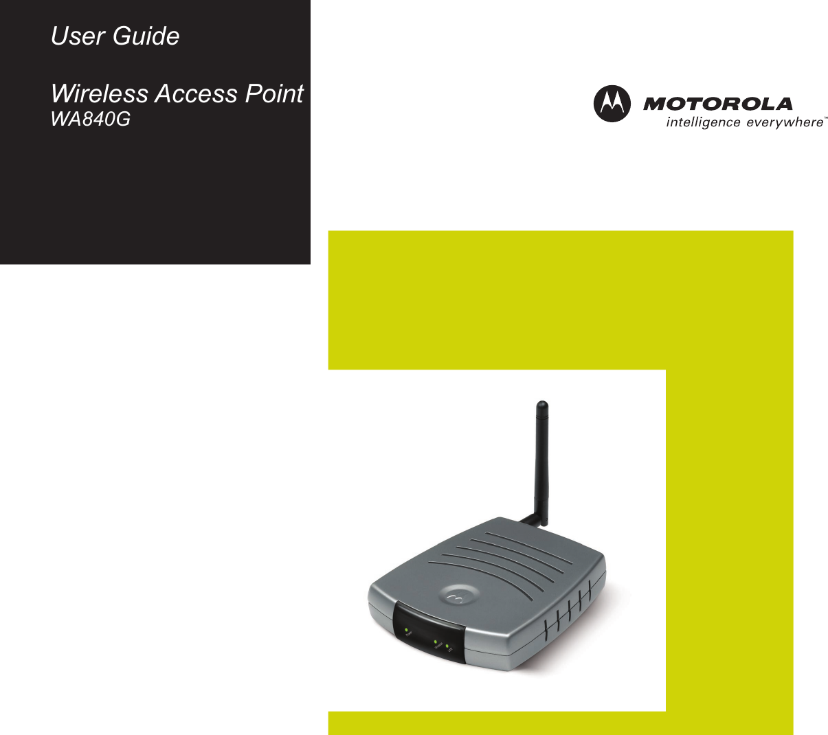
ARRIS WA840GV2 Wireless Access Point User Manual WA840G
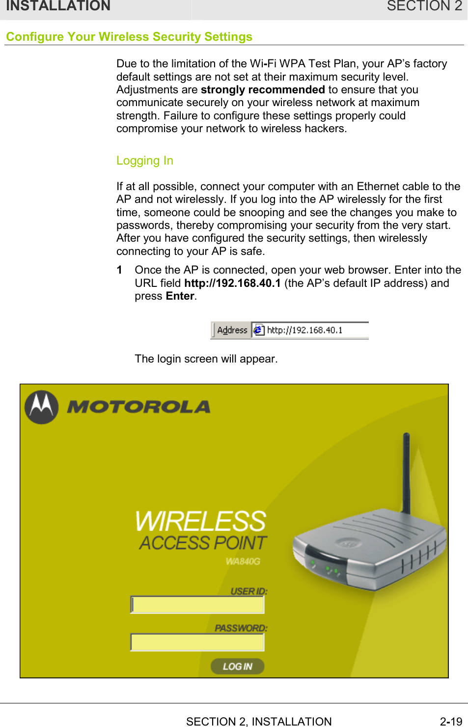
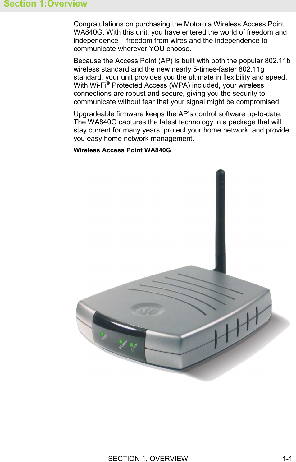
ARRIS Group, Inc. Wireless Access Point WA840G
UserManual.wiki
>
ARRIS
>
WA840GV2 User Manual
Manual
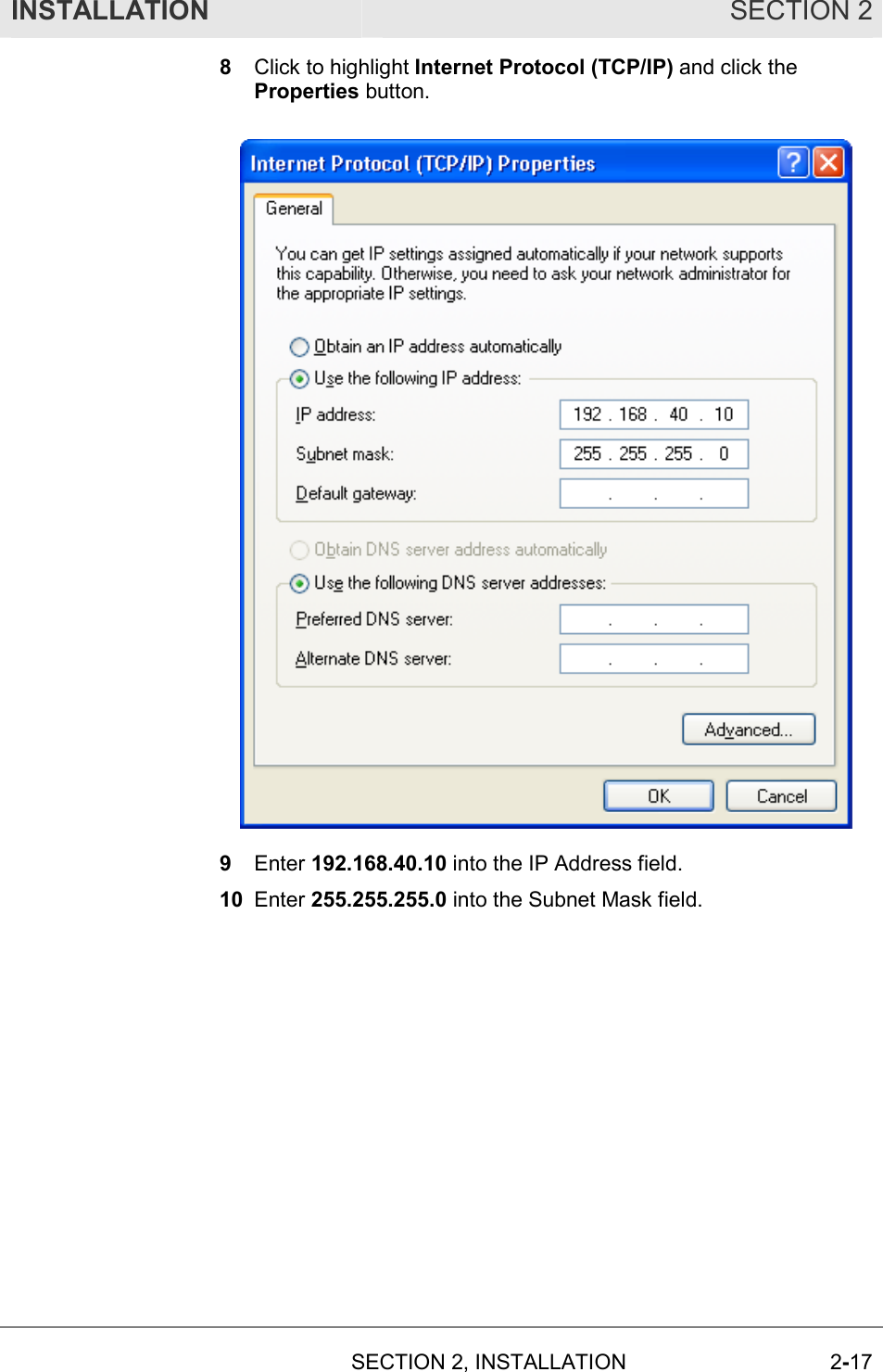
Navigation menu
Upload a User Manual
Namespaces
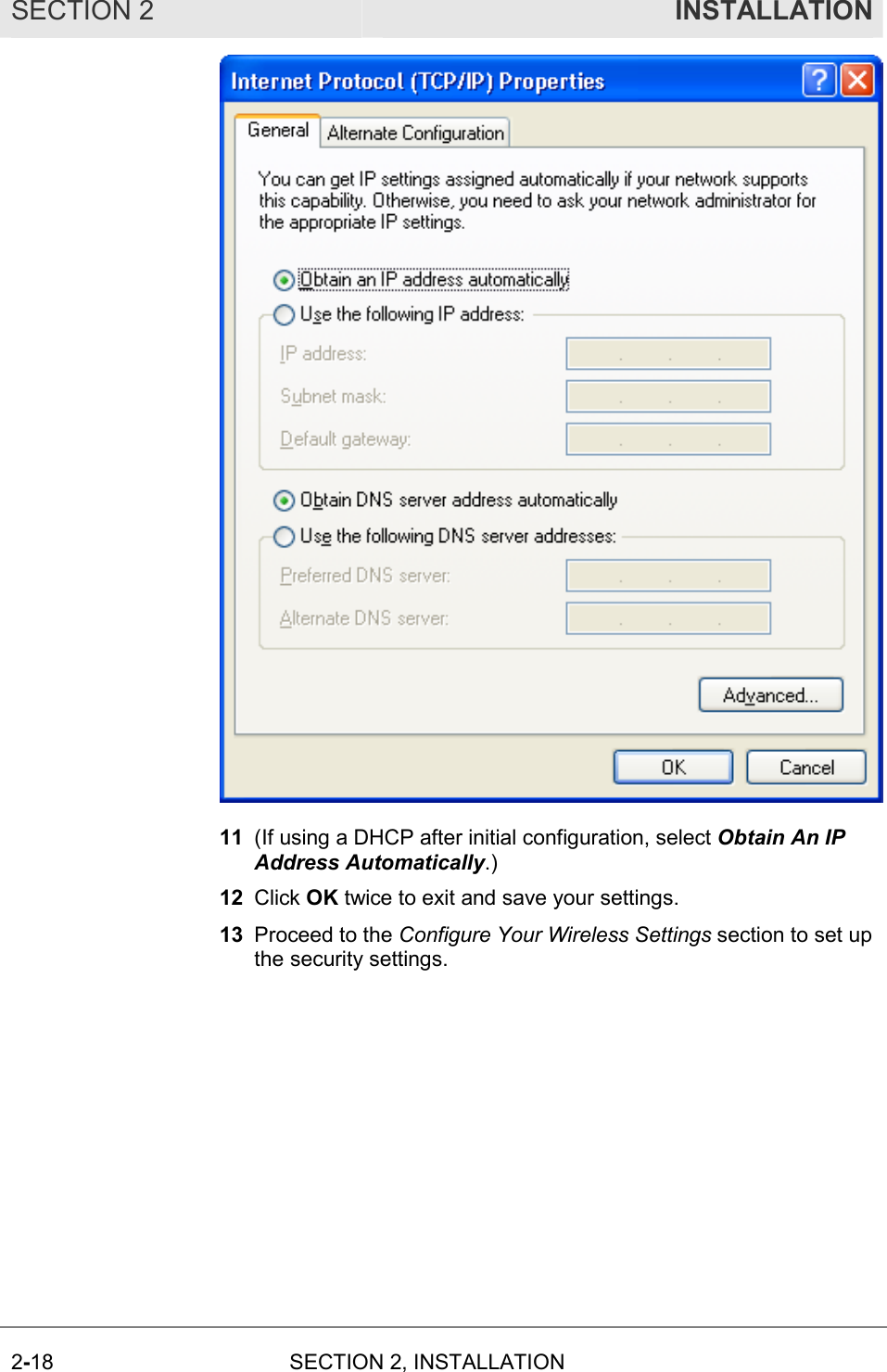
Wiki Guide
HTML
PDF
Info
Views
User Manual
Discussion / Help
Navigation
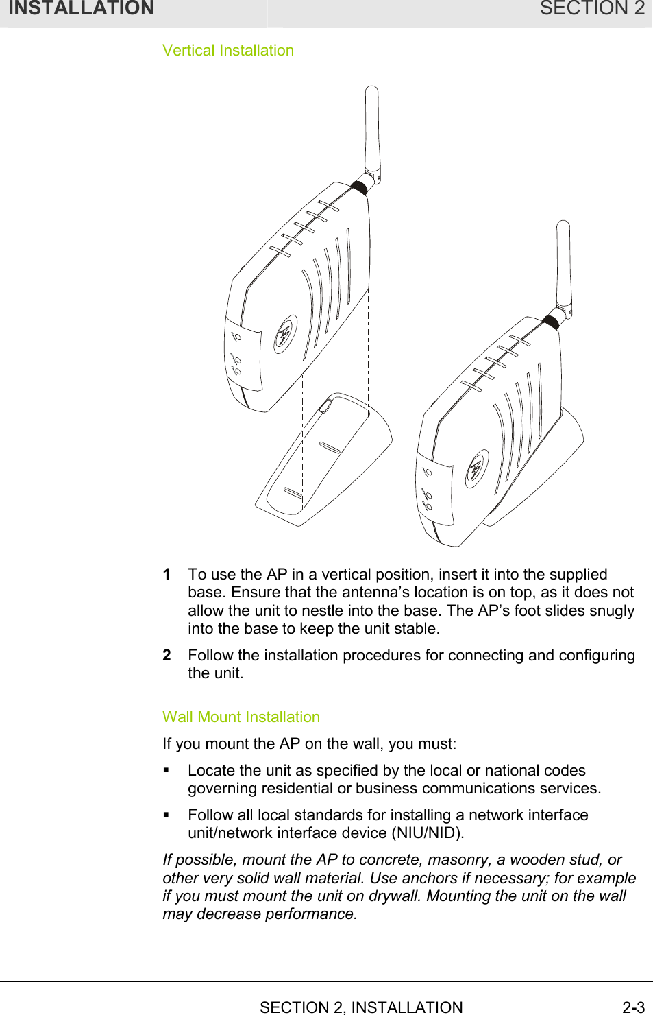
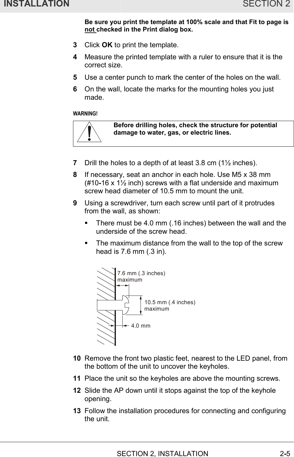
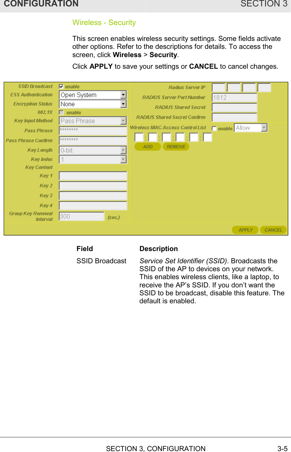
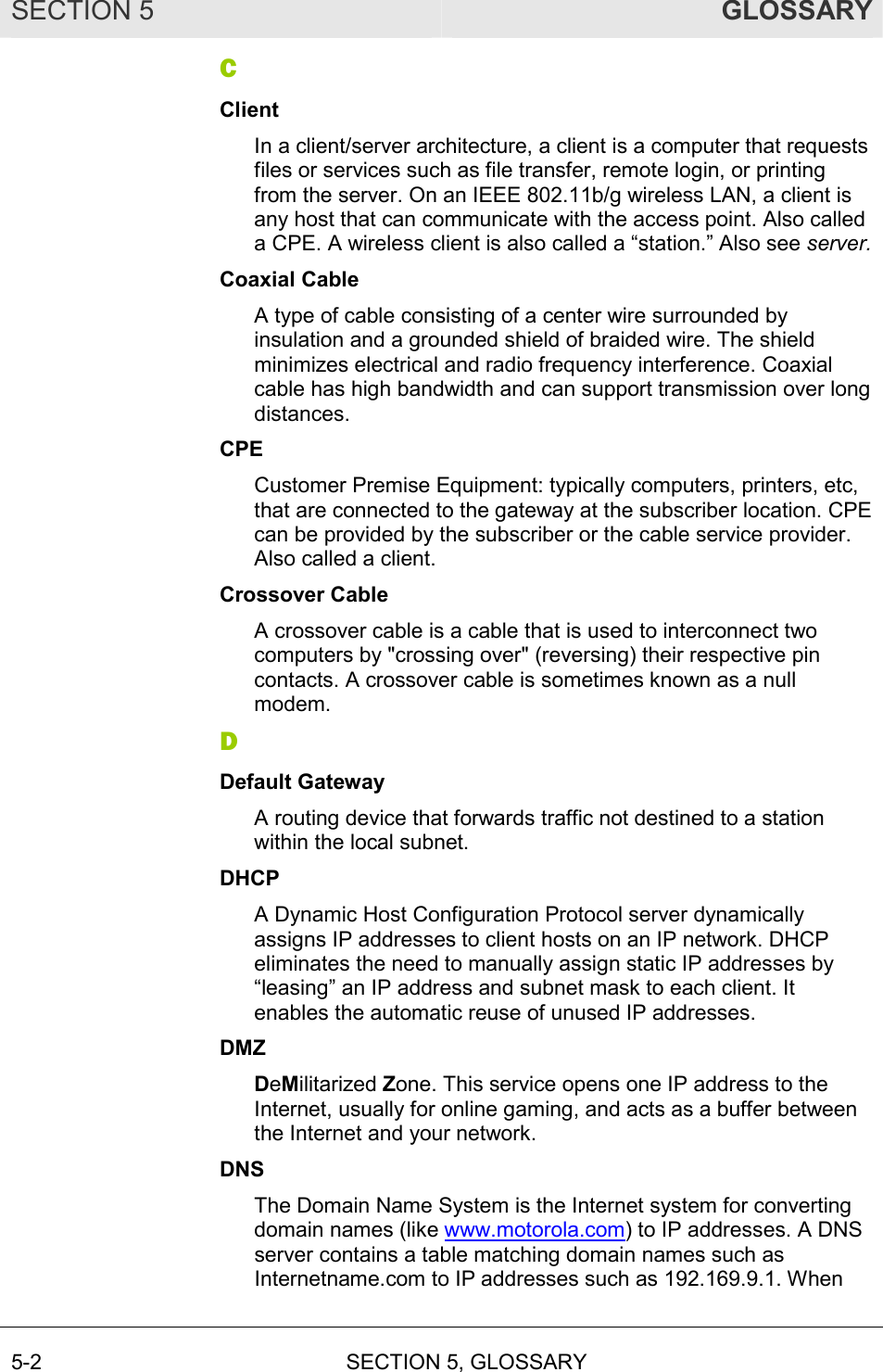
![SECTION 2 INSTALLATION 2-4 SECTION 2, INSTALLATION To mount your AP on the wall: 1 Print the Wall Mounting Template. 3.15”[80.00mm]INPUT VOLTAGE: +5VDC, 2AFCC ID: F2NWA840GFOR HOME OR OFFICE USETested To ComplyWith FCC StandardsMODEL: WA840GWIRELESS MAC: AB CD EF 01 23 45MADE IN TAIWANMODEL WA840GPART NUMBER: AAAAAA-BBB-CCS/N: PPPPMMYJJJSSSSSCAABBCCCC The illustration is drawn at a one-to-one scale, which means that when printed, it provides the exact dimensions required to mount the unit. 2 Click the Print icon or choose Print from the File menu to display the Print dialog box. (A sample print dialog follows.)](https://usermanual.wiki/ARRIS/WA840GV2/User-Guide-392676-Page-19.png)