ARRIS WN825G Wireless Notebook Adapter User Manual WN825G

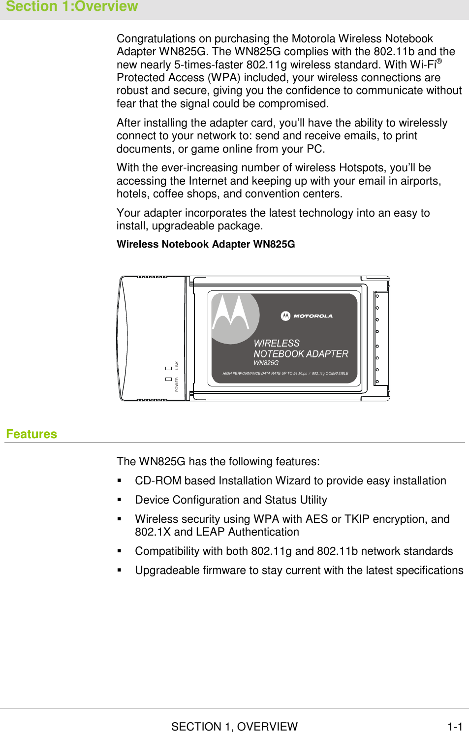
ARRIS Group, Inc. Wireless Notebook Adapter WN825G

Manual

User GuideWireless NotebookAdapterWN825G
     WARNING: TO PREVENT FIRE OR SHOCK HAZARD, DO NOT EXPOSE THIS PRODUCT TO RAIN OR MOISTURE. THE UNIT MUST NOT BE EXPOSED TO DRIPPING OR SPLASHING. DO NOT PLACE OBJECTS FILLED WITH LIQUIDS, SUCH AS VASES, ON THE UNIT. CAUTION: TO ENSURE REGULATORY COMPLIANCE, USE ONLY THE PROVIDED POWER AND INTERFACE CABLES. CAUTION: DO NOT OPEN THE UNIT. DO NOT PERFORM ANY SERVICING OTHER THAN THAT CONTAINED IN THE INSTALLATION AND TROUBLESHOOTING INSTRUCTIONS. REFER ALL SERVICING TO QUALIFIED SERVICE PERSONNEL. This device must be installed and used in strict accordance with the manufacturer’s instructions as described in the user documentation that comes with the product. Postpone router installation until there is no risk of thunderstorm or lightning activity in the area. Do not overload outlets or extension cords, as this can result in a risk of fire or electric shock. Overloaded AC outlets, extension cords, frayed power cords, damaged or cracked wire insulation, and broken plugs are dangerous. They may result in a shock or fire hazard. Route power supply cords so that they are not likely to be walked on or pinched by items placed upon or against them. Pay particular attention to cords where they are attached to plugs and convenience receptacles, and examine the point where they exit from the product. Place this equipment in a location that is close enough to an electrical outlet to accommodate the length of the power cord. Place this equipment on a stable surface. When using this device, basic safety precautions should always be followed to reduce the risk of fire, electric shock and injury to persons, including the following: •   Read all of the instructions {listed here and/or in the user manual} before you operate this equipment. Give particular attention to all safety precautions. Retain the instructions for future reference. •   Comply with all warning and caution statements in the instructions. Observe all warning and caution symbols that are affixed to this equipment. •   Comply with all instructions that accompany this equipment. •   Avoid using this product during an electrical storm. There may be a risk of electric shock from lightning. For added protection for this product during a lightning storm, or when it is left unattended and unused for long periods of time, unplug it from the wall outlet, and disconnect the cable system. This will prevent damage to the product due to lightning and power surges. •   Operate this product only from the type of power source indicated on the product’s marking label. If you are not sure of the type of power supplied to your home, consult your dealer or local power company. •   Upon completion of any service or repairs to this products, ask the service technician to perform safety checks to determine that the product is in safe operating condition. It is recommended that the customer install an AC surge protector in the AC outlet to which this device is connected. This is to avoid damaging the equipment by local lightning strikes and other electrical surges. Different types of cord sets may be used for connections to the main supply circuit. Use only a main line cord that complies with all applicable product safety requirements of the country of use. Installation of this product must be in accordance with national wiring codes. Place unit to allow for easy access when disconnecting the power cord/adapter of the device from the AC wall outlet. Wipe the unit with a clean, dry cloth. Never use cleaning fluid or similar chemicals. Do not spray cleaners directly on the unit or use forced air to remove dust. This product was qualified under test conditions that included the use of the supplied cables between system components. To be in compliance with regulations, the user must use these cables and install them properly. Connect the unit to a grounding type AC wall outlet using the power adapter supplied with the unit. Do not cover the device, or block the airflow to the device with any other objects. Keep the device away from excessive heat and humidity and keep the device free from vibration and dust. Installation must at all times conform to local regulations. FCC Compliance Class B Digital Device This equipment has been tested and found to comply with the limits for a Class B digital device, pursuant to Part 15 of the FCC Rules. These limits are designed to provide reasonable protection against harmful interference in a residential environment. This equipment generates, uses, and can radiate radio frequency energy and, if not installed and used in accordance with the instructions, may cause harmful interference to radio communications. However, there is no guarantee that interference will not occur in a particular installation. If this equipment does cause harmful interference to radio or television reception, which can be determined by turning the equipment off and on, the user is encouraged to try to correct the interference by one of the following measures: •   Reorient or relocate the receiving antenna. •   Increase the separation between the equipment and receiver. •   Connect the equipment into an outlet on a circuit different from that to which the receiver is connected. •   Consult the dealer or an experienced radio/TV technician for help. CAUTION: Changes or modifications not expressly approved by Motorola for compliance could void the user’s authority to operate the equipment.
    Canadian Compliance This Class B digital apparatus meets all requirements of the Canadian Interference Causing Equipment Regulations. Cet appareil numérique de la classe B respects toutes les exigences du Règlement sur le matériel brouilleur du Canada. FCC Declaration of Conformity Motorola, Inc., Broadband Communications Sector, 101 Tournament Drive, Horsham, PA 19044, 1-215-323-1000, declares under sole responsibility that the WR850G, WE800G, WA840G, WN825G, WPCI810G, and BR700 compile with 47 CFR Parts 2 and 15 of the FCC Rules as a Class B digital device. This device complies with Part 15 of FCC Rules. Operation of the device is subject to the following two conditions: (1) This device may not cause harmful interference, and (2) this device must accept any interference that may cause undesired operation. Wireless LAN Information The WR850G, WE800G, WA840G, WN825G, and WPCI810G Wireless LAN products are wireless network products that uses Direct Sequence Spread Spectrum (DSSS) radio technology. This product is designed to be inter-operable with any other wireless DSSS type product that complies with: •   The IEEE 802.11 Standard on Wireless LANs (Revision B), as defined and approved by the Institute of Electrical Electronics Engineers. •   The Wireless Fidelity (WiFi) certification as defined by the Wireless Ethernet Compatibility Alliance (WECA). Wireless LAN and your Health The WR850G, WE800G, WA840G, WN825G, and WPCI810G, like other radio devices, emits radio frequency electromagnetic energy, but operates within the guidelines found in radio frequency safety standards and recommendations.  Restrictions on Use of Wireless Devices In some situations or environments, the use of wireless devices may be restricted by the proprietor of the building or responsible representatives of the organization. For example, these situations may include: •   Using wireless equipment on board an airplane. •   Using wireless equipment in any environment where the risk of interference to other devices or services is perceived or identified as harmful. If you are uncertain of the applicable policy for the use of wireless equipment in a specific organization or environment (such as airports), you are encouraged to ask for authorization to use the device prior to turning on the equipment.  The manufacturer is not responsible for any radio or television interference caused by unauthorized modification of the devices included with this product, or the substitution or attachment of connecting cables and equipment other than specified by the manufacturer. Correction of interference caused by such unauthorized modification, substitution, or attachment is the responsibility of the user. The manufacturer and its authorized resellers or distributors are not liable for any damage or violation of government regulations that may arise from failing to comply with these guidelines. FCC Certification The WR850G, WE800G, WA840G, WN825G, and WPCI810G contains a radio transmitter and accordingly has been certified as compliant with 47 CFR Part 15 of the FCC Rules for intentional radiators. Products that contain a radio transmitter are labeled with FCC ID and the FCC logo. FCC Radiation Exposure Statement: This equipment complies with FCC radiation exposure limits set forth for an uncontrolled environment.This device complies with FCC RF Exposure limits set forth for an uncontrolled environment, under 47 CFR 2.1093 paragraph (d)(2). This transmitter must not be co-located or operating in conjunction with any other antenna or transmitter.Canada - Industry Canada (IC) The wireless radio of this device complies with RSS 210 ans RSS 102 of Industry Canada. This Class B digitral device complies with Canadian ICES-003 (NMB-003). Cet appareil numérique de la classe B respects toutes les exigences du Règlement sur le matériel brouilleur du Canada  Copyright © 2003 by Motorola, Inc. All rights reserved. No part of this publication may be reproduced in any form or by any means or used to make any derivative work (such as translation, transformation or adaptation) without written permission from Motorola, Inc. Motorola reserves the right to revise this publication and to make changes in content from time to time without obligation on the part of Motorola to provide notification of such revision or change. Motorola provides this guide without warranty of any kind, either implied or expressed, including, but not limited to, the implied warranties of merchantability and fitness for a particular purpose. Motorola may make improvements or changes in the product(s) described in this manual at any time.  MOTOROLA and the Stylized M Logo are registered in the US Patent & Trademark Office. Microsoft Windows screen shots are used by permission of Microsoft Corporation. All other product or service names are the property of their respective owners. © Motorola, Inc. 2003  Motorola declares that WN825G ( FCC ID: ACQWN825G ) is limited in CH1~CH11 by specified firmware controlled in USA.
 CONTENTS I  Contents Section 1:Overview _______________________ 1-1 Features ................................................................................................................ 1-1 Understanding your User Guide ......................................................................... 1-2 Box Contents ........................................................................................................ 1-2 Simple Home Network Diagram .......................................................................... 1-3 Wireless Connections.......................................................................................... 1-3 Adapter Card Physical Description..................................................................... 1-4 Top of Adapter Card............................................................................................1-4 Bottom of Adapter Card.......................................................................................1-5 Section 2:Installation______________________ 2-1 Device Configuration Setup................................................................................. 2-1 Section 3:Configuration ___________________ 3-1 Connecting to an Existing Wireless Network..................................................... 3-1 Configuring a New Wireless Network ................................................................. 3-3 Configuring Properties for an Existing Wireless Network................................ 3-7 Preferred Networks – Setting up the Connection Order ................................. 3-10 Move up and Move down buttons .....................................................................3-11 Advanced Selection Rules ................................................................................3-11 Removing a Network From Your Preferred Network List................................ 3-12 Viewing Site Monitor Information...................................................................... 3-14 Viewing Link Status............................................................................................ 3-17 Viewing Network Statistics................................................................................ 3-18 Activating LEAP.................................................................................................. 3-18 Diagnostics ......................................................................................................... 3-20 Viewing Adapter Product Information .............................................................. 3-21 Removing the Wireless Adapter........................................................................ 3-22 Section 4:Troubleshooting _________________ 4-1 Contact Us ..........................................................................................................4-1 Hardware Solutions.............................................................................................. 4-1 My computer is experiencing difficulty connecting to the wireless network..................................................................................................................4-1 I would like to test to see if my Internet connection is alive...........................................4-2 Section 5:Glossary _______________________ 5-1
 SECTION 1, OVERVIEW 1-1 Section 1:Overview Congratulations on purchasing the Motorola Wireless Notebook Adapter WN825G. The WN825G complies with the 802.11b and the new nearly 5-times-faster 802.11g wireless standard. With Wi-Fi® Protected Access (WPA) included, your wireless connections are robust and secure, giving you the confidence to communicate without fear that the signal could be compromised. After installing the adapter card, you’ll have the ability to wirelessly connect to your network to: send and receive emails, to print documents, or game online from your PC. With the ever-increasing number of wireless Hotspots, you’ll be accessing the Internet and keeping up with your email in airports, hotels, coffee shops, and convention centers. Your adapter incorporates the latest technology into an easy to install, upgradeable package. Wireless Notebook Adapter WN825G LINKPOWERHIGH PERFORMANCE 54 Mbits/s DATA RATE  /  DRAFT 802.11G COMPLIANTHIGH PERFORMANCE DATA RATE UP TO 54 Mbps  /  802.11g COMPATIBLE Features The WN825G has the following features: !  CD-ROM based Installation Wizard to provide easy installation !  Device Configuration and Status Utility !  Wireless security using WPA with AES or TKIP encryption, and 802.1X and LEAP Authentication !  Compatibility with both 802.11g and 802.11b network standards !  Upgradeable firmware to stay current with the latest specifications
SECTION 1  OVERVIEW 1-2 SECTION 1, OVERVIEW  Understanding your User Guide The User Guide is subdivided into the following sections: Overview  Provides a general introduction for using your product, the type of technology used, and recommended practices for using it.  Installation  Provides instructions for installing the hardware and setting up the firmware to get your adapter up and running.  Configuration and Status  Provides details for using the Configuration and Status Utility to manage your unit.  Troubleshooting Provides a list of frequently asked questions and possible solutions.  Glossary  List of terms and acronyms used in this book or used in the field of wireless networking and networking in general. Box Contents Your box contains the following: WN825GCD-ROM Quick StartGuideLI NKPOWERHIGH PERFORMANCE 5 4 Mbits/s DATA RATE   /  DRAFT 802.11G COMPLIAN THIGH PE RFOR MANCE  DATA RATE  UP TO 5 4 Mbps  /   8 02.11g  COMPATIBL ECD-ROMWN825GGetting Started1234Motorol a WN825G  Wireless Notebook AdapterCheck that your box contains  these items. (User Gui de: Secti on 1)Insert the Installat ion WizardCD-ROM(User Gui de: Secti on 2)Installthe software for your unitfrom the CD-ROM(User Gui de: Secti on 2)Insert your card into the PC cardbus slot(User Gui de: Secti on 2)MGBI 5069 30- 00 1If you need as sis tance, call:1-8 77- 4 66-86 467 days  a wee k,  24 hou rs  a dayYou can als o che ck for the latest developments at:www.motorola.com/ broa dba nd/ n et workingQuick StartGuideGetting Started1234Motorola WN825G Wireless Notebook AdapterCheck that your box contains these items. (User Guide: Section 1)InserttheInstallation Assistant CD-ROM(User Guide: Section 2)Installthesoftware for your unit from the CD-ROM(User Guide: Section 2)Insert your card into the PC(User Guide: Section 2)CD-ROMWN825GQuickStartGuide
OVERVIEW SECTION 1  SECTION 1, OVERVIEW 1-3 Simple Home Network Diagram Your wireless notebook adapter card, allows you to access files, printers, and an Internet connection on your network. A sample Local Area Network (LAN) is shown below:  In the example above, the Internet communicates with the modem which in turn communicates with the router. The router acts as the gateway to your network, sending information to whichever device asks for information. The adapter card enables your notebook PC to be part of the wireless network. Wireless Connections Your wireless adapter card uses a radio transmission technology defined by the Institute of Electrical and Electronics Engineers (IEEE) called 802.11 Wireless Fidelity (Wi-Fi). This standard is subdivided into distinct categories of speed and the frequency spectrum used, designated by the lower case letter after the standard.  For example, your adapter card can work with both the ‘b’ and ‘g’ specifications. The 802.11b specification transmits data rates up to 11 Mbps while the 802.11g specification transmits data rates up to 54 Mbps. Both standards operate in the 2.4 GHz range. These are theoretical speeds so your performance may vary.
SECTION 1  OVERVIEW 1-4 SECTION 1, OVERVIEW  Adapter Card Physical Description Top of Adapter Card The following illustration shows the top of the WN825G: LINKPOWERHIGH PERFORMANCE 54 Mbits/s DATARATE/DRAFT 802.11G COMPLIANTHIGH PERFORMANCE DATA RATE UP TO 54 Mbps  /  802.11g COMPATIBLE12 The WN825G has the following features:  Feature  Description 1  Power LED  Indicates that the card is powered. 2  Link LED  Indicates the activity of the wireless network traffic
OVERVIEW SECTION 1  SECTION 1, OVERVIEW 1-5 Bottom of Adapter Card The following illustration shows the bottom of the WN825G: MAC addressMAC: AB CD EF 01 23 45This device is approved as Motorola Model WN825GFCC ID: F2NWN825GWith FCC StandardsFor Home Or Office Use Tes ted To ComplyMade in TaiwanS/N: PPPPMMYJJJSSSSSCAABBCCCCPART NUMBER: 498518-001-00MODEL: WN825G The following describes the features on the bottom of the WN825G: Feature Description Label  Includes the model number, part number, serial number, and MAC Address MAC Address  Location of the adapter card’s MAC Address
 SECTION 2, INSTALLATION 2-1 Section 2:Installation To install the software and hardware: 1  Insert the supplied CD-ROM into the CD-ROM drive. 2  The software automatically starts the Installation Wizard program.  3  Follow the prompts to setup your adapter card.   If Windows 98SE prompts you for the original Windows CD-ROM, insert the CD-ROM, and direct Windows to its proper location (for example, D:\WIN98). 4  Locate an empty CardBus slot on your notebook PC. 5  With the adapter card product-label and LEDs facing up, insert the adapter card into the CardBus slot:   6  Complete the installation instructions supplied on the CD-ROM. Device Configuration Setup After installing the adapter card and software, you will need to connect to a network. Refer to Section 3:Configuration for information on how to create detailed connectivity profiles so you can connect to a wireless network, setup security, and setup modes of operation.
  SECTION 3, CONFIGURATION  3-1 Section 3:Configuration You can use the information in this section to: !  Discover available wireless networks !  Setup operation modes !  Create connectivity profiles !  Setup security !  Monitor the wireless network / environment !  Diagnostic discovery Connecting to an Existing Wireless Network After the adapter card is installed, a red antenna icon is displayed on your computer in the system tray. It is the first icon shown in the following illustration:  The icon is red when your PC is not connected to a wireless network or green if it is connected.
SECTION 3  CONFIGURATION 3-2  SECTION 3, CONFIGURATION  To connect to an existing wireless network: 1  Double-click the antenna icon. The Connect to Wireless Network window is displayed:   The window displays any available wireless networks detected.  2  Highlight the network you want to access. 3  If prompted, enter a Network key. Enter the network key you used to set up security on your access point. 4  Click Connect.
CONFIGURATION SECTION 3   SECTION 3, CONFIGURATION  3-3 Configuring a New Wireless Network To configure a new wireless network: 1  Double-click the antenna icon in the system tray. The Connect to Wireless Network window is displayed:
SECTION 3  CONFIGURATION 3-4  SECTION 3, CONFIGURATION  2  Click Advanced. The Motorola Wireless Configuration Utility window is displayed:
CONFIGURATION SECTION 3   SECTION 3, CONFIGURATION  3-5 3  Click Add. The Wireless Network Properties window is displayed:  4  Enter information for the new wireless network. Field Description Network name (SSID)  Enter a Network Name (SSID) of no more than 32 alphanumeric characters. This is the SSID for a particular wireless access point.  Data encryption (WEP enabled)  Select if the type of security encryption algorithm used on this network is WEP64 or WEP128.  Network Authentication (Shared mode) Select if your access point requires WEP authentication. Network key  The security key that applies to data encryption or the network authentication. This can be entered in ASCII or hexadecimal.
SECTION 3  CONFIGURATION 3-6  SECTION 3, CONFIGURATION  Field Description Key format  Enter the format you used in the Network Key field – ASCII or hexadecimal.  Key length  Determines the strength of the network key. The options are 128-bit or 64-bit.  Key index (advanced)  There are four Keys (1, 2, 3, 4) that can be selected. The key selected must match the router’s key.  The key is provided for me automatically Select if the key will automatically be provided. Most often, the key is not automatically provided, so you may have to un-check this box and enter the network key. This is a computer-to-computer  (ad hoc) network  Select if the network you are creating is a computer-to computer (ad hoc) network.  5  After entering the information for this network, click OK. The Motorola Wireless Configuration Utility window is again displayed and the new network is listed in the Preferred networks area.
CONFIGURATION SECTION 3   SECTION 3, CONFIGURATION  3-7 Configuring Properties for an Existing Wireless Network To configure network properties for an existing wireless network: 1  Double-click the antenna icon in the system tray. The Connect to Wireless Network window is displayed:
SECTION 3  CONFIGURATION 3-8  SECTION 3, CONFIGURATION  2  Click Advanced. The Motorola Wireless Configuration Utility window is displayed:  3  In the Available networks list or the Preferred networks list, highlight the network you want to configure. In the Available networks area, click Configure or in the Preferred networks area, click Properties.
CONFIGURATION SECTION 3   SECTION 3, CONFIGURATION  3-9 4  The Wireless Network Properties window is displayed:  5  If the network you want to configure is open (no encryption, no authentication), click OK and this network is added to the list of preferred networks.  6  If the network is not open and requires WEP data encryption, click Data encryption (WEP enabled). 7  If the network is not open and requires network authentication, click Network Authentication (Shared mode). 8  Edit the fields that you want to change for the selected wireless network. For additional information about the fields on this window, refer to Configuring a New Wireless Network.  9  Click OK.
SECTION 3  CONFIGURATION 3-10  SECTION 3, CONFIGURATION  Preferred Networks – Setting up the Connection Order There are two ways you can specify the order that the adapter will use to try to connect to an available network in your Preferred networks list: !  Using the Move up and Move down buttons !  Using Advanced selection rules
CONFIGURATION SECTION 3   SECTION 3, CONFIGURATION  3-11 Move up and Move down buttons Use the Move up and Move down buttons to move a network up and down in the list of Preferred networks. The adapter tries to connect to a wireless network in the order you specify in the Preferred networks list.  To move a network within the list: 1  Highlight the network you want to move. 2  Click either the Move up or Move down button depending on where you want the selected network to appear in the list. Advanced Selection Rules You can select some advanced rules for the adapter to use in displaying and selecting a network from the list of Preferred networks. To select an advanced rule to display and choose a network: 1  On the Motorola Wireless Configuration Utility window, on the Wireless Networks tab, click Advanced. The Advanced window is displayed:  2  Choose one of the three ways to display and choose networks from the Preferred network list. Choosing Access point networks only or Computer-to-computer networks only will limit the number of networks in your preferred list.
SECTION 3  CONFIGURATION 3-12  SECTION 3, CONFIGURATION  Removing a Network From Your Preferred Network List To remove a wireless network from your preferred network list: 1  Double-click the antenna icon in the system tray. The Connect to Wireless Network window is displayed:
CONFIGURATION SECTION 3   SECTION 3, CONFIGURATION  3-13 2  Click Advanced. The Motorola Wireless Configuration Utility window is displayed:  3  In the Preferred networks list, highlight the network you want to remove. 4  Click Remove. The network is removed from your preferred network list.
SECTION 3  CONFIGURATION 3-14  SECTION 3, CONFIGURATION  Viewing Site Monitor Information To view site monitor information: 1  Double-click the antenna icon in the system tray. 2  On the Connect to Wireless Network window, click Advanced. 3  Click the Site Monitor tab.   The Visible Networks list provides information about all of the detected networks. It lists the Network Name (SSID), Channel, Signal Strength, and Security. 4  Highlight a network to get more information about that network in the Selected Network area of the window. This area provides information about which wireless transmission standard is used on the network, a graphic representation of the signal strength, and the supported transmission rates.
CONFIGURATION SECTION 3   SECTION 3, CONFIGURATION  3-15 5  To obtain more information about a selected network, click Advanced. The Advanced Site Monitor window is displayed:   This window provides detailed information about the network you selected. 6  To start a log of network activity, click Start Log. The Save log file as window is displayed:  7  Select a drive and directory to store the networks.log file. 8  Click Save.
SECTION 3  CONFIGURATION 3-16  SECTION 3, CONFIGURATION  9  The adapter saves a log of the information listed on the Advanced Site Monitor window to the networks.log file. The information is sent to the file approximately every six seconds. The log is a comma-delimited list that can be imported to a spreadsheet to enable you to view the activity on the network over an specific time period. 10  Click Stop Log to stop the log information from being sent to the networks.log file. 11  To freeze the display, click Freeze.
CONFIGURATION SECTION 3   SECTION 3, CONFIGURATION  3-17 Viewing Link Status To view link status: 1  Double-click the antenna icon in the system tray. 2  Click Advanced.  3  Click the Link Status tab. The Link Status tab provides information about the wireless network:
SECTION 3  CONFIGURATION 3-18  SECTION 3, CONFIGURATION  Viewing Network Statistics To view statistics for the network you are connected to: 1  Double-click the antenna icon in the system tray. 2  Click Advanced. The Motorola Wireless Configuration Utility window is displayed. 3  Click the Statistics tab. The Statistics tab provides information about the wireless network:  Activating LEAP Lightweight Extensible Authentication Protocol (LEAP) is an authentication implementation of 802.1X by Cisco, which provides a challenge-response authentication mechanism and dynamic WEP key assignment.  1  Double-click the antenna icon in the system tray.
CONFIGURATION SECTION 3   SECTION 3, CONFIGURATION  3-19 2  Click Advanced. The Motorola Wireless Configuration Utility window is displayed. Click the LEAP tab.  3  Click Enable LEAP to activate the function. 4  To add a network, click Properties. The LEAP Network Properties window displays.  5  Enter the required information and click OK.
SECTION 3  CONFIGURATION 3-20  SECTION 3, CONFIGURATION  6  To remove a network, highlight the network in the Leap Enabled Networks window and click Remove. 7  Click Apply and then OK to save your changes. Diagnostics This tab will help you, in conjunction with technical support, to isolate problems that might be occurring with your adapter. 1  Double-click the antenna icon in the system tray. 2  Click Advanced. The Motorola Wireless Configuration Utility window is displayed. 3  Click the Diagnostics tab.  4  Various diagnostic tests are available. Select an individual test to learn more about its function.   5  Click to enable the desired test and then click Run.  The Results, Passed or Failed, are displayed in the next column.
CONFIGURATION SECTION 3   SECTION 3, CONFIGURATION  3-21  Viewing Adapter Product Information To view product information for the adapter installed in your PC: 1  Double-click the antenna icon in the system tray. 2  Click Advanced. The Motorola Wireless Configuration Utility window is displayed. 3  Click the Information tab. The Information tab provides the firmware version number and hardware and adapter details about the adapter card:
SECTION 3  CONFIGURATION 3-22  SECTION 3, CONFIGURATION  Removing the Wireless Adapter You can safely remove the Wireless Adapter while the PC is operating.  To remove the adapter: 1  Locate the Device Eject icon located in your system tray. In the illustration below, it is the third icon from the left; the picture of a card and a left-pointing arrow.  2  Double-click the Device Eject icon. The Unplug or Eject Hardware window is displayed:
CONFIGURATION SECTION 3   SECTION 3, CONFIGURATION  3-23 3  Highlight the device you want to remove. 4  Click STOP. The Stop a Hardware device window is displayed:  5  Confirm that the device listed in the window is the device you want to stop. 6  Click OK. After you receive a message telling you the device is stopped, you can safely remove the Wireless Adapter.
 SECTION 4, TROUBLESHOOTING 1 Section 4:Troubleshooting This section details possible solutions to common problems that might occur in using the WN825G.  Contact Us If you are unable to locate a solution here, please access our website at www.motorola.com/broadband/networking for the latest information.  You can also reach us at 1-877-466-8646 7 days a week, 24 hours a day. Hardware Solutions My computer is experiencing difficulty connecting to the wireless network.   !  Ensure that your PC and wireless access point is powered on. !  Ensure that your wireless adapter is installed correctly and is active.   !  Ensure that your wireless adapter and access point radio signal is enabled.  Review your access point’s documentation for further instructions. !  Ensure that your wireless adapter for your PC and the wireless access point have the same security settings that will allow your computer to access the wireless network. Refer to the Configuration section of the documentation that came with your access point. !  Verify that the Access Control List (ACL) is not configured to block your PC. Refer to the Configuration section of the documentation that came with your access point. !  Ensure that your wireless adapter is within range of your access point or is not behind and obstruction; for example, metal structures will interfere with the signal, as will 2.4 GHz cordless phones, and microwaves. !  Ensure that your access point antenna is connected.
SECTION 4  TROUBLESHOOTING  4-2 SECTION 4, TROUBLESHOOTING  I would like to test to see if my Internet connection is alive. For this, you will use the ping command to test the connection. Before attempting, determine the IP Address of your adapter. 1  Open a command prompt by clicking Start and Run. For Windows 98 and ME, in the Open field, type command and press Enter or OK. For Windows 2000 and XP, type cmd. Or, navigate using your Start button to Programs>Accessories>Command Prompt.  2  In the Command window, type “ipconfig”. !  You should see an IP address for your adapter, for example: Ethernet Adapter Local Area Connection: Connection-specific DNS Suffix.: Example.example.example.com. IP Address. . . . . . . . . . . . : 192.168.10.1 Subnet Mask . . . . . . . . . . . : 255.255.255.0 Default Gateway . . . . . . . . . : 192.168.10.1 3  In the Command window, type ping the Router’s IP address and press the Enter key. The router’s IP address is most likely the default gateway. !  If you receive a reply (the first word will be Reply…), then your computer is connected to the router. Proceed to Step 4. !  If you do NOT receive a reply, try from a different computer to verify that the first PC is not the cause of the problem. 4  In the Command window, type ping and your ISP’s default gateway and press the Enter key. You can determine your ISP’s default gateway by examining your modem and or router. Refer to the instructions provided with your modem/router. !  If you receive a reply (It might look something like this: Reply from 216.109.125.72…), then your connection to the Internet is alive and well. !  If you do NOT receive a reply, try from a different computer to verify that the first PC is not the cause of the problem. 5  If you cannot determine your ISP’s default gateway, ping Yahoo.com or another known web location.
 SECTION 5, GLOSSARY 5-1 Section 5:Glossary  A Access Point (AP) A device that provides wireless LAN connectivity to wireless clients (stations). Adapter A device or card that connects a computer, printer, or other peripheral device to the network or to some other device. A wireless adapter connects a computer to the wireless LAN. Address translation  See NAT. Ad-Hoc Network A temporary local area network connecting AP clients together, usually just for the duration of the communication session.  The clients communicate directly to each other and not through an established, such as through a router. Also known as: IBSS (Independent Basic Service Set).   ASCII The American Standard Code for Information Interchange refers to alphanumeric data for processing and communication compatibility among various devices; normally used for asynchronous transmission. B Bandwidth The transmission capacity of a medium in terms of a range of frequencies. Greater bandwidth indicates the ability to transmit more data over a given period of time.  bps Bits Per Second Broadband A communications medium that can transmit a relatively large amount of data in a given time period.  BSS Basic Service Set.  A configuration of Access Points that communicate with each other without resorting any infrastructure. Also known as Ad-Hoc networks.  Also see ESS.
SECTION 5  GLOSSARY 5-2 SECTION 5, GLOSSARY  C Client In a client/server architecture, a client is a computer that requests files or services such as file transfer, remote login, or printing from the server.  On an IEEE 802.11b/g wireless LAN, a client is any host that can communicate with the access point. Also called a CPE. A wireless client is also called a “station.” Also see server. Coaxial Cable A type of cable consisting of a center wire surrounded by insulation and a grounded shield of braided wire. The shield minimizes electrical and radio frequency interference. Coaxial cable has high bandwidth and can support transmission over long distances. CPE Customer Premise Equipment: typically computers, printers, etc, that are connected to the gateway at the subscriber location. CPE can be provided by the subscriber or the cable service provider. Also called a client. Crossover Cable A crossover cable is a cable that is used to interconnect two computers by "crossing over" (reversing) their respective pin contacts. A crossover cable is sometimes known as a null modem.  D Default Gateway A routing device that forwards traffic not destined to a station within the local subnet. DHCP A Dynamic Host Configuration Protocol server dynamically assigns IP addresses to client hosts on an IP network. DHCP eliminates the need to manually assign static IP addresses by “leasing” an IP address and subnet mask to each client. It enables the automatic reuse of unused IP addresses. DMZ DeMilitarized Zone.  This service opens one IP address to the Internet, usually for online gaming, and acts as a buffer between the Internet and your network. DNS The Domain Name System is the Internet system for converting domain names (like www.motorola.com) to IP addresses. A DNS server contains a table matching domain names such as Internetname.com to IP addresses such as 192.169.9.1. When
GLOSSARY SECTION 5  SECTION 5, GLOSSARY 5-3 you access the world-wide web, a DNS server translates the URL displayed on the browser to the destination website IP address. The DNS lookup table is a distributed Internet database; no one DNS server lists all domain name to IP address matches. Domain Name A unique name, such as motorola.com, that maps to an IP address. Domain names are typically much easier to remember than are IP addresses.  See DNS. Download To copy a file from one computer to another. You can use the Internet to download files from a server to a computer.  Driver Software that enables a computer to interact with a network or other device. For example, there are drivers for printers, monitors, graphics adapters, modems, Ethernet, USB, HPNA, and many others. DSL Digital Subscriber Line DSSS Direct-Sequence Spread Spectrum. DSSS is a transmission technology used in WLAN transmissions where a data signal at the sending station is combined with a higher data rate bit sequence, or chipping code, that divides the user data according to a spreading ratio. The chipping code is a redundant bit pattern for each bit that is transmitted, which increases the signal's resistance to interference. If one or more bits in the pattern are damaged during transmission, the original data can be recovered due to the redundancy of the transmission.  Dynamic IP Address An IP address that is temporarily leased to a host by a DHCP server. The opposite of Static IP Address. E ESS An Extended Service Set (ESS) is a set of two or more BSSs that form a single subnetwork.  See also BSS. Ethernet The most widely used LAN type, also known as IEEE 802.3. The most common Ethernet networks are 10Base-T, which provide transmission speeds up to 10 Mbps, usually over unshielded, twisted-pair wire terminated with RJ-45 connectors. Fast Ethernet (100Base-T) provides speeds up to 100 Mbps. “Base” means “baseband technology” and “T” means “twisted pair cable.”’
SECTION 5  GLOSSARY 5-4 SECTION 5, GLOSSARY  Each Ethernet port has a physical address called the MAC address. Also see MAC address. Event A message generated by a device to inform an operator or the network management system that something has occurred. F Firewall A security software system on the some devices that enforces an access control policy between the Internet and the LAN for protection. Firmware Code written onto read-only memory (ROM) or programmable read-only memory (PROM). Once firmware has been written onto the ROM or PROM, it is retained even when the device is turned off.  Firmware is upgradeable. FTP File Transfer Protocol is a standard Internet protocol for exchanging files between computers. FTP is commonly used to download programs and other files to a computer from web pages on Internet servers. G Gateway A device that enables communication between networks using different protocols. See also router. GUI Graphical User Interface H Hexadecimal A base-sixteen numbering system that uses sixteen sequential numbers (0 to 9 and the letters A to F) as base units before adding a new position. On computers, hexadecimal is a convenient way to express binary numbers. Host In IP, a host is any computer supporting end-user applications or services with full two-way network access. Each host has a unique host number that combined with the network number forms its IP address.  Host also can mean: !  A computer running a web server that serves pages for one or more web sites belonging to organization(s) or individuals
GLOSSARY SECTION 5  SECTION 5, GLOSSARY 5-5 !  A company that provides this service !  In IBM environments, a mainframe computer I ICMP Internet Control Message Protocol is a protocol used for error, problem, and informational messages sent between IP hosts and gateways. ICMP messages are processed by the IP software and are not usually apparent to the end-user. IEEE The Institute of Electrical and Electronics Engineers, Inc. (http://www.ieee.org) is an organization that produces standards, technical papers, and symposiums for the electrical and electronic industries and is accredited by ANSI.  802.11b and 802.11g are examples of standards they have produced. Internet A worldwide collection of interconnected networks using TCP/IP. IP Internet Protocol is a set of standards that enable different types of computers to communicate with one another and exchange data through the Internet. IP provides the appearance of a single, seamless communication system and makes the Internet a virtual network. IP Address A unique 32-bit value that identifies each host on a TCP/IP network. TCP/IP networks route messages based on the destination IP address.  For a Class C network, the first 24 bits are the network address and the final 8 bits are the host address; in dotted-decimal format it appears “network.network.network.host.” ISDN Integrated Services Digital Network ISP Internet Service Provider L LAN Local Area Network.  A local area network provides a full-time, high-bandwidth connection over a limited area such as a home, building, or campus. Ethernet is the most widely used LAN standard.
SECTION 5  GLOSSARY 5-6 SECTION 5, GLOSSARY  LEAP Lightweight Extensible Authentication Protocol (LEAP) is an authentication implementation of 802.1X by Cisco, which provides a challenge-response authentication mechanism and dynamic WEP key assignment. M MAC Address The Media Access Control address is a unique, 48-bit value permanently saved in the ROM at the factory to identify each Ethernet network device. It is expressed as a sequence of 12 hexadecimal digits printed on the unit’s label. You need to provide the MAC Address to the cable service provider. Also called an Ethernet address, physical address, hardware address, or NIC address. MB One megabyte; equals 1,024 x 1,024 bytes, 1,024 kilobytes, or about 8 million bits. Mbps Million bits per second (megabits per second). A rate of data transfer. MTU The Maximum Transmission Unit is the largest amount of data that can be transmitted in one discrete message on a given physical network. The MTU places an upper bound on the size of a message that can be transferred by the network in a single frame. Messages exceeding the MTU must be fragmented before transmission, and reassembled at the destination. Multicast A data transmission sent from one sender to multiple receivers. See also broadcast and unicast. N NAT Network Address Translation is an Internet standard for a LAN to use one set of IP addresses for internal traffic and a second set of IP addresses for external traffic. NAT provides some security because the IP addresses of LAN computers are invisible on the Internet. Network Two or more computers connected to communicate with each other. Networks have traditionally been connected using some kind of wiring.
GLOSSARY SECTION 5  SECTION 5, GLOSSARY 5-7 NIC A Network Interface Card converts computer data to serial data in a packet format that it sends over the LAN. A NIC is installed in an expansion slot or can be built-in. Every Ethernet NIC has a MAC address permanently saved in its ROM. P Packet The unit of data that is routed between the sender and destination on the Internet or other packet-switched network.  PCMCIA The Personal Computer Memory Card International Association sets international standards for connecting peripherals to portable computers. Laptop computers typically have a PCMCIA slot that can hold one or two PC Cards to provide features such as Ethernet or wireless connectivity. PING A network utility that tests host reachability by sending a small packet to the host and waiting for a reply. If you PING a computer IP address and receive a reply, you know the computer is reachable over the network. It also stands for “Packet Internet Groper.” Port Triggering A mechanism that allows incoming communication with specified applications.  PPP Point-to-Point Protocol is used to transport other protocols, typically for simple links over serial lines. It is most commonly used to access the Internet with a dial-up modem. PPPoE Point-to-Point Protocol over Ethernet.  Used by many DSL Internet Service Providers for broadband connection. PPTP Point-to-Point Tunneling Protocol encapsulates other protocols. It is a new technology to create VPNs developed jointly by several vendors. Private IP Address An IP address assigned to a computer on the LAN by the DHCP server for a specified lease time. Private IP addresses are invisible to devices on the Internet. See also Public IP Address.
SECTION 5  GLOSSARY 5-8 SECTION 5, GLOSSARY  Protocol A formal set of rules and conventions for exchanging data. Different computer types (for example PC, UNIX, or mainframe) can communicate if they support common protocols. Public IP Address The IP address assigned by the service provider. A public IP address is visible to devices on the Internet. See also Private IP Address. R RJ-11 The most common type of connector for household or office phones. RJ-45 An 8-pin modular connector; the most common connector type for 10Base-T or 100Base-T Ethernet networks. Roaming The ability to transfer your wireless session from one AP to another AP seamlessly. ROM Read-Only Memory. Router On IP networks, a device connecting at least two networks, which may or may not be similar. A router is typically located at a gateway between networks. A router operates on OSI network layer 3. It filters packets based on the IP address, examining the source and destination IP addresses to determine the best route on which to forward them.  A router is often included as part of a network switch. A router can also be implemented as software on a computer. Routing Table A table listing available routes that is used by a router to determine the best route for a packet. RTS Request To Send. S Server In a client/server architecture, a dedicated computer that supplies files or services such as file transfer, remote login, or printing to clients.  Also see client.
GLOSSARY SECTION 5  SECTION 5, GLOSSARY 5-9 Service Provider A company providing Internet connection services to subscribers. SMTP Simple Mail Transfer Protocol is a standard Internet protocol for transferring e-mail. Static IP Address An IP address that is permanently assigned to a host. Normally, a static IP address must be assigned manually. The opposite of Dynamic IP Address. Station IEEE 802.11b term for wireless client. Subscriber A user who accesses television, data, or other services from a service provider. Subnet Mask A methodology that determines what the router will examine for the destination of an IP address. A router delivers packets using the network address. Switch On an Ethernet network, a switch filters frames based on the MAC address, in a manner similar to a bridge. A switch is more advanced because it can connect more than two segments. T TCP Transmission Control Protocol on OSI transport layer four, provides reliable transport over the network for data transmitted using IP (network layer three). It is an end-to-end protocol defining rules and procedures for data exchange between hosts on top of connectionless IP. TCP uses a timer to track outstanding packets, checks error in incoming packets, and retransmits packets if requested. TCP/IP The Transmission Control Protocol/Internet Protocol suite provides standards and rules for data communication between networks on the Internet. It is the worldwide Internetworking standard and the basic communications protocol of the Internet. Tunnel To place packets inside other packets to send over a network. The protocol of the enclosing packet is understood by each endpoint, or tunnel interface, where the packet enters and exits the network. VPNs rely on tunneling to create a secure network.
SECTION 5  GLOSSARY 5-10 SECTION 5, GLOSSARY  Tunneling requires the following protocol types:  !  A carrier protocol, such as TCP, used by the network that the data travels over  !  An encapsulating protocol, such as IPSec, L2F, L2TP, or PPTP, that is wrapped around the original data  !  A passenger protocol, such as IP, for the original data U UDP User Datagram Protocol. A method used along with the IP to send data in the form of message units (datagram) between network devices over a LAN or WAN.  Unicast A point-to-point data transmission sent from one sender to one receiver. This the normal way you access websites. See also multicast. USB Universal Serial Bus is a computer interface for add-on devices such as printers, scanners, mice, modems, or keyboards. USB supports data transfer rates of 12 Mbps and plug-and-play installation. You can connect up to 127 devices to a single USB port. V VoIP Voice over Internet Protocol is a method to exchange voice, fax, and other information over the Internet. Voice and fax have traditionally been carried over traditional telephone lines of the PSTN (Public Switched Telephone Network) using a dedicated circuit for each line. VoIP enables calls to travel as discrete data packets on shared lines. VoIP is an important part of the convergence of computers, telephones, and television into a single integrated information network. VPN A virtual private network is a private network that uses “virtual” connections (tunnels) routed over a public network (usually the Internet) to provide a secure and fast connection; usually to users working remotely at home or in small branch offices. A VPN connection provides security and performance similar to a dedicated link (for example, a leased line), but at much lower cost.
GLOSSARY SECTION 5  SECTION 5, GLOSSARY 5-11 W WAN A wide-area network provides a connection over a large geographic area, such as a country or the whole world. The bandwidth depends on need and cost, but is usually much lower than for a LAN. WAP Wireless Access Point or Wireless Access Protocol. See also Access Point. WEP Wired Equivalent Privacy encryption protects the privacy of data transmitted over a wireless LAN. WEP uses keys to encrypt and decrypt transmitted data. The access point must authenticate a client before it can transfer data to another client. WEP is part of IEEE 802.11b. Wi-Fi® Wireless fidelity (pronounced why'-fy) brand name applied to products supporting IEEE 802.11b/g. WLAN Wireless LAN. WPA Wi-Fi Protected Access.  A security regimen developed by IEEE for protection of data on a WLAN. WWW World Wide Web. An interface to the Internet that you use to navigate and hyperlink to information.
MGBI494075-00107/03Visit our website at:www.motorola.com/broadband

Navigation menu