ARRIS WPS870G Wireless 802.11g High Speed AP Router User Manual Pirnt Server
ARRIS Group, Inc. Wireless 802.11g High Speed AP Router Pirnt Server
UserManual.wiki
>
ARRIS
>
WPS870G User Manual
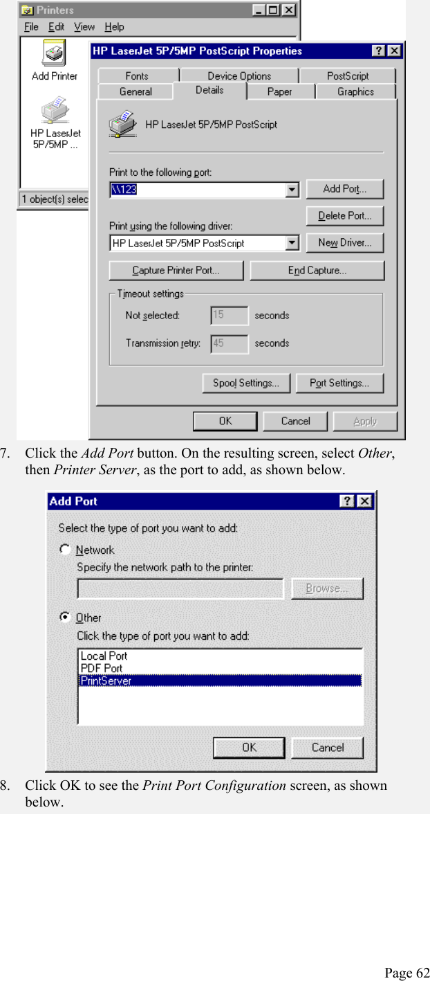
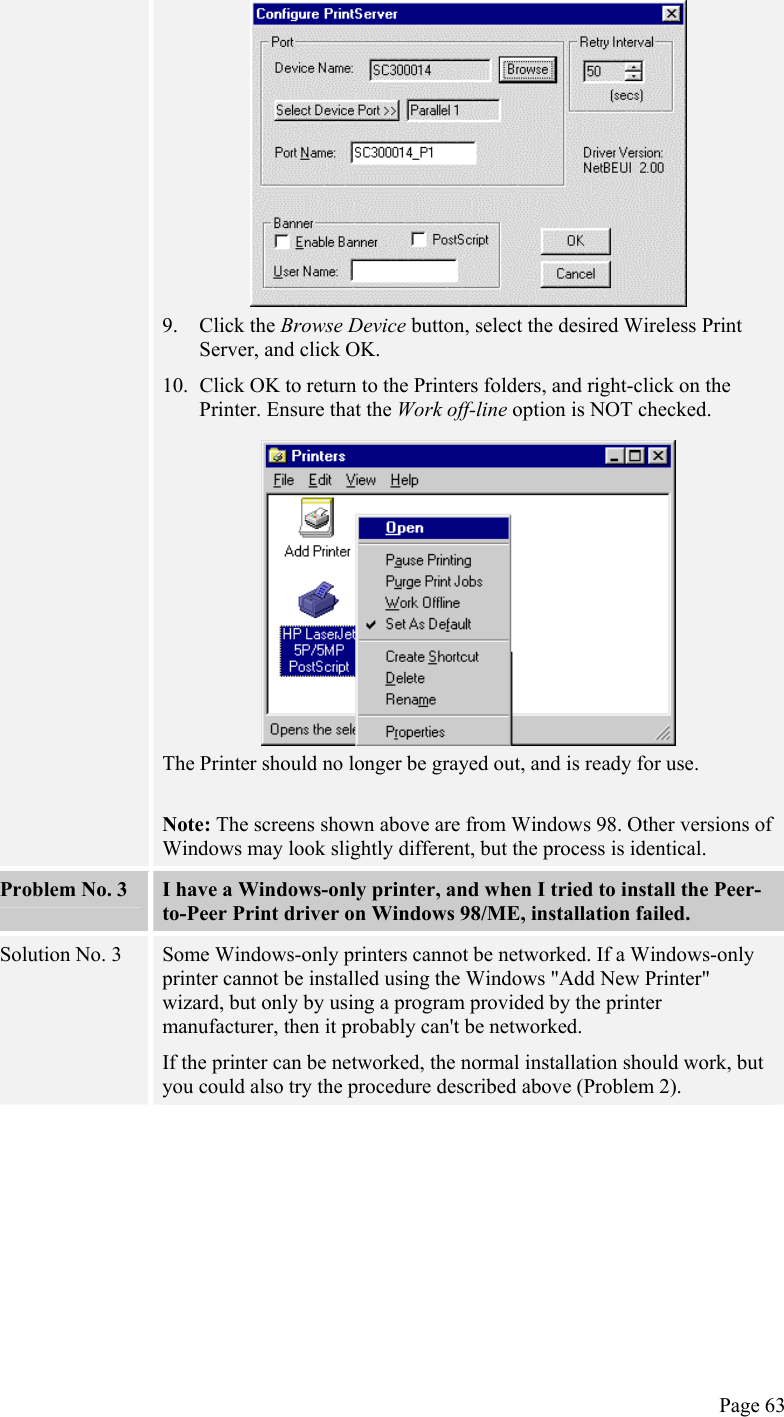
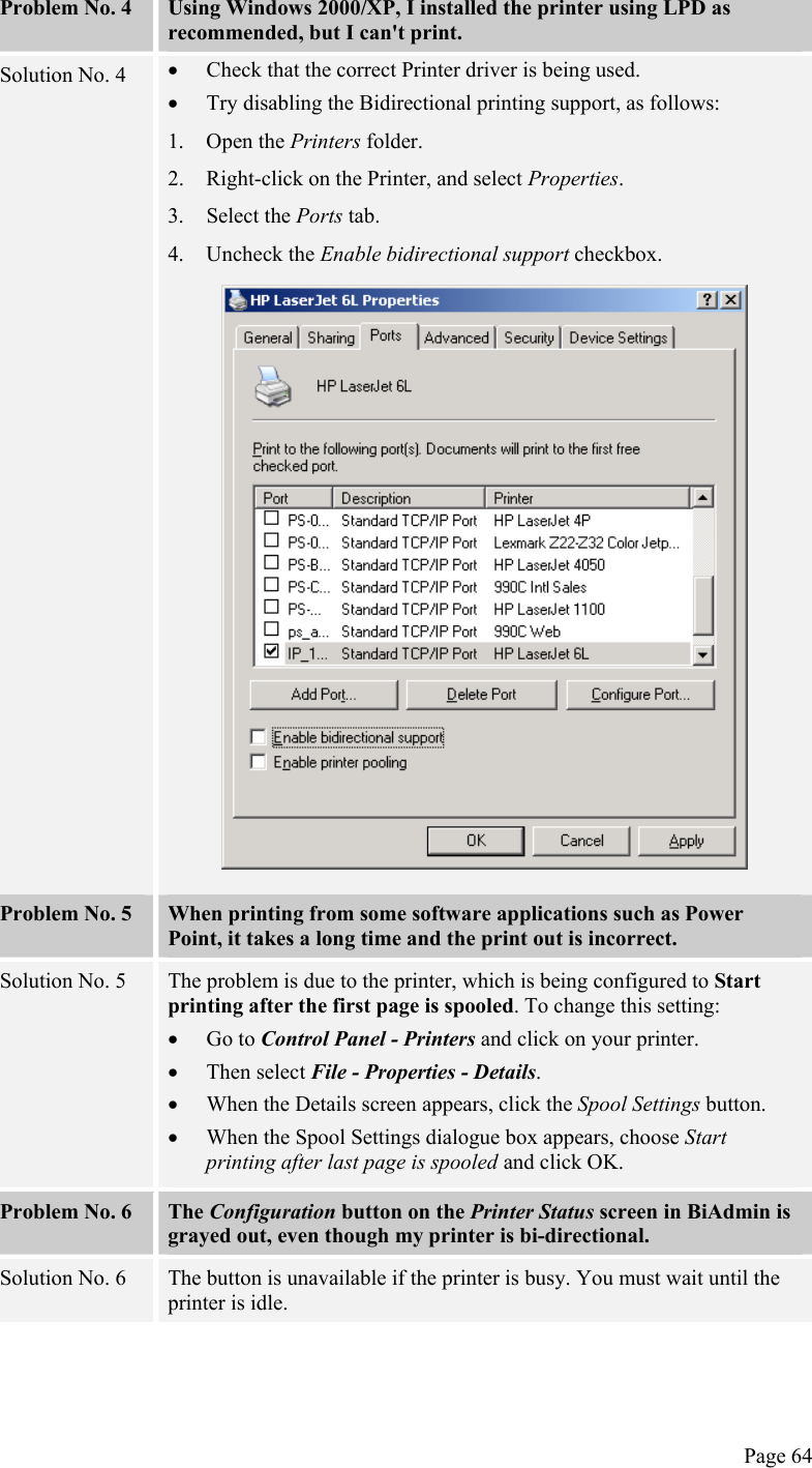
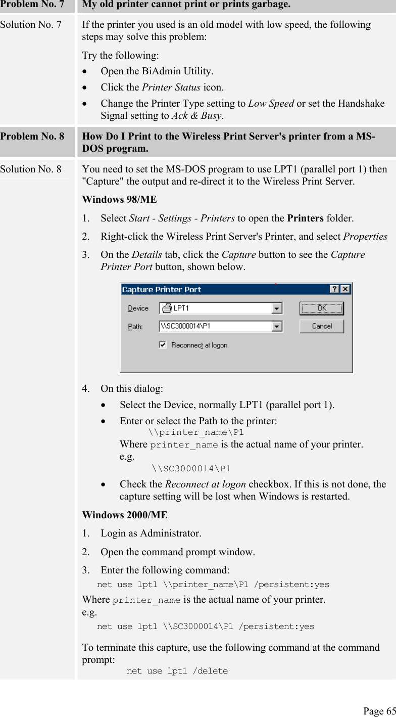
>
Users Manual Part 2
Contents
1.
Users Manual Part 1
2.
Users Manual Part 2
Users Manual Part 2
Navigation menu
Upload a User Manual
Namespaces
Wiki Guide
HTML
PDF
Info
Views
User Manual
Discussion / Help
Navigation
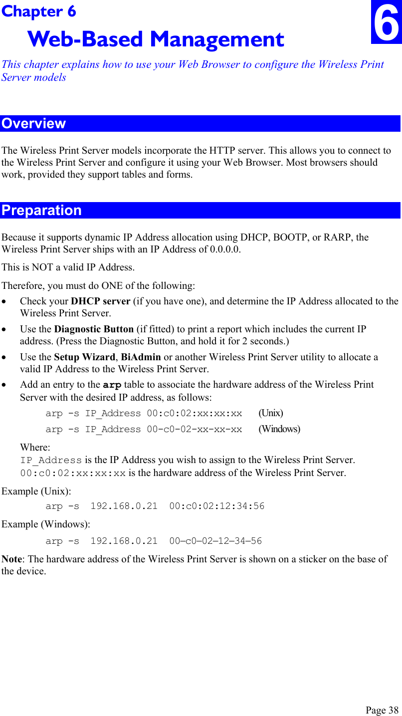
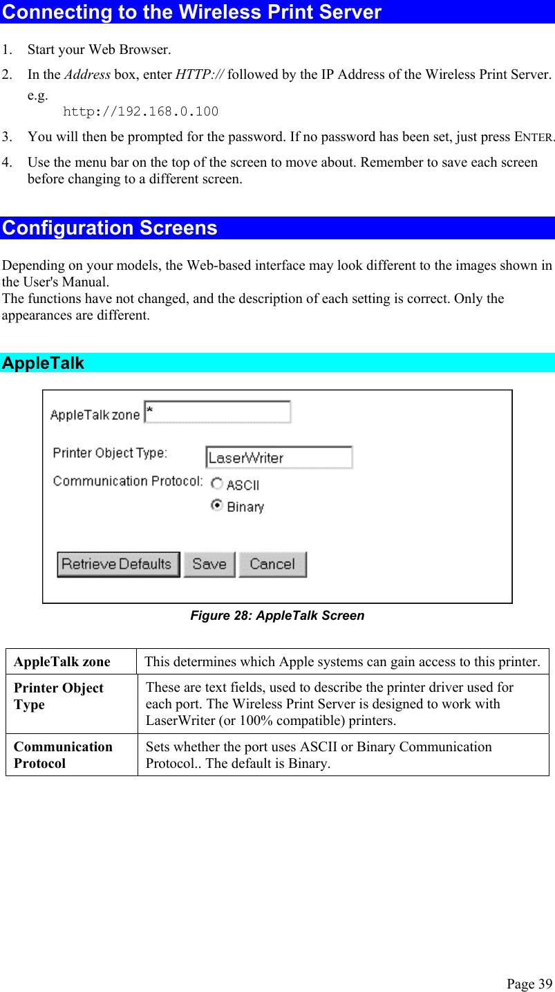
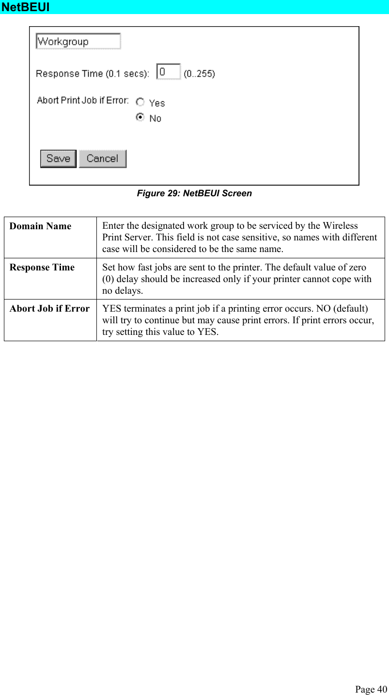
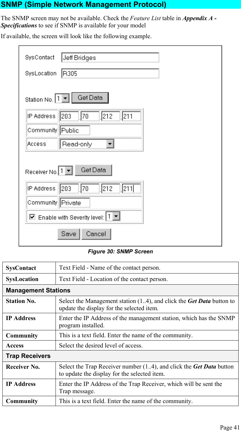
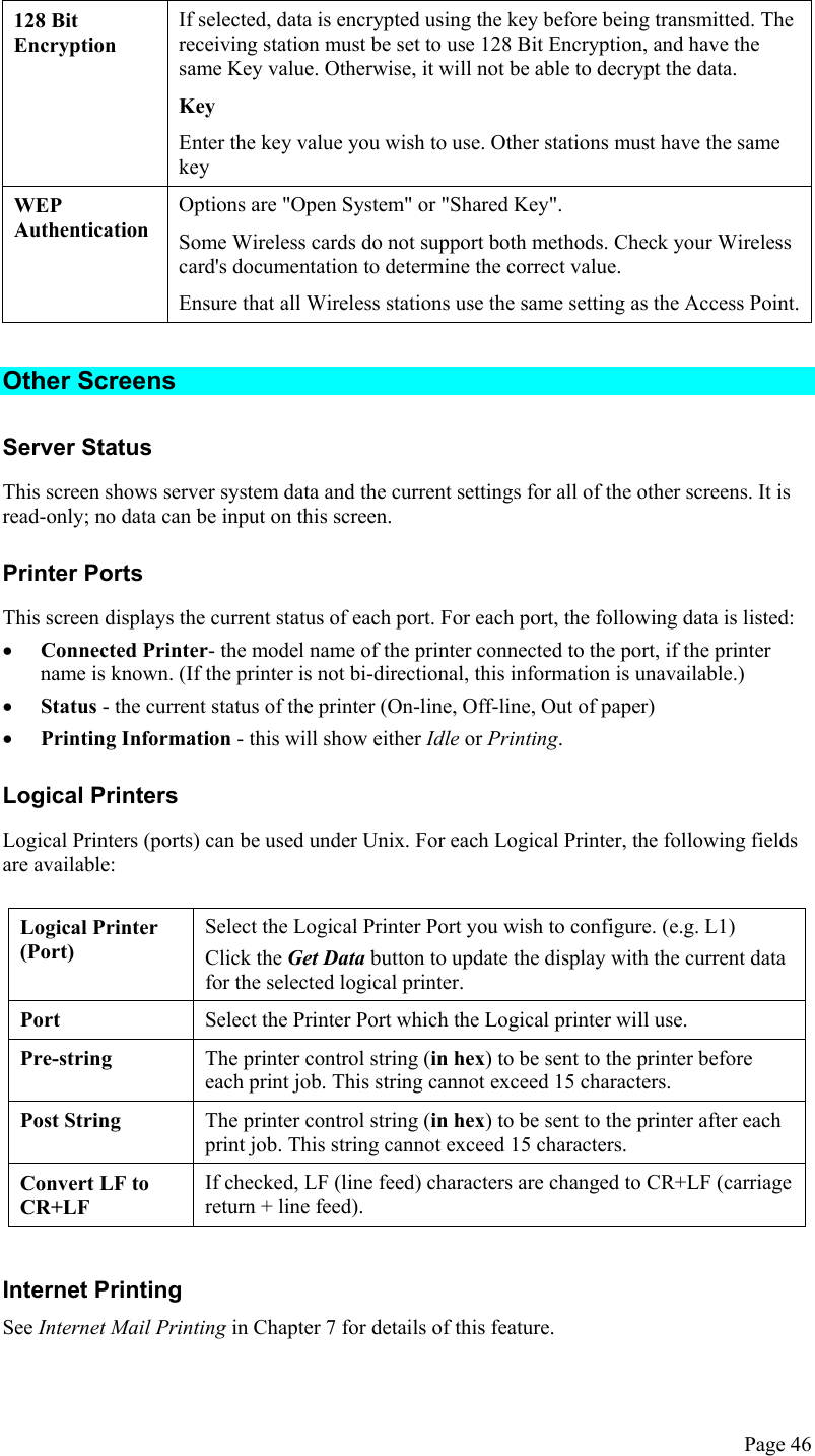
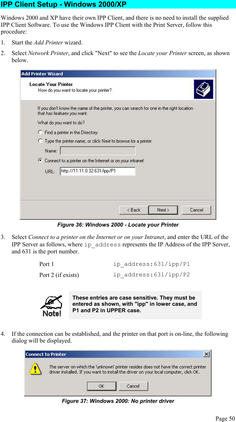
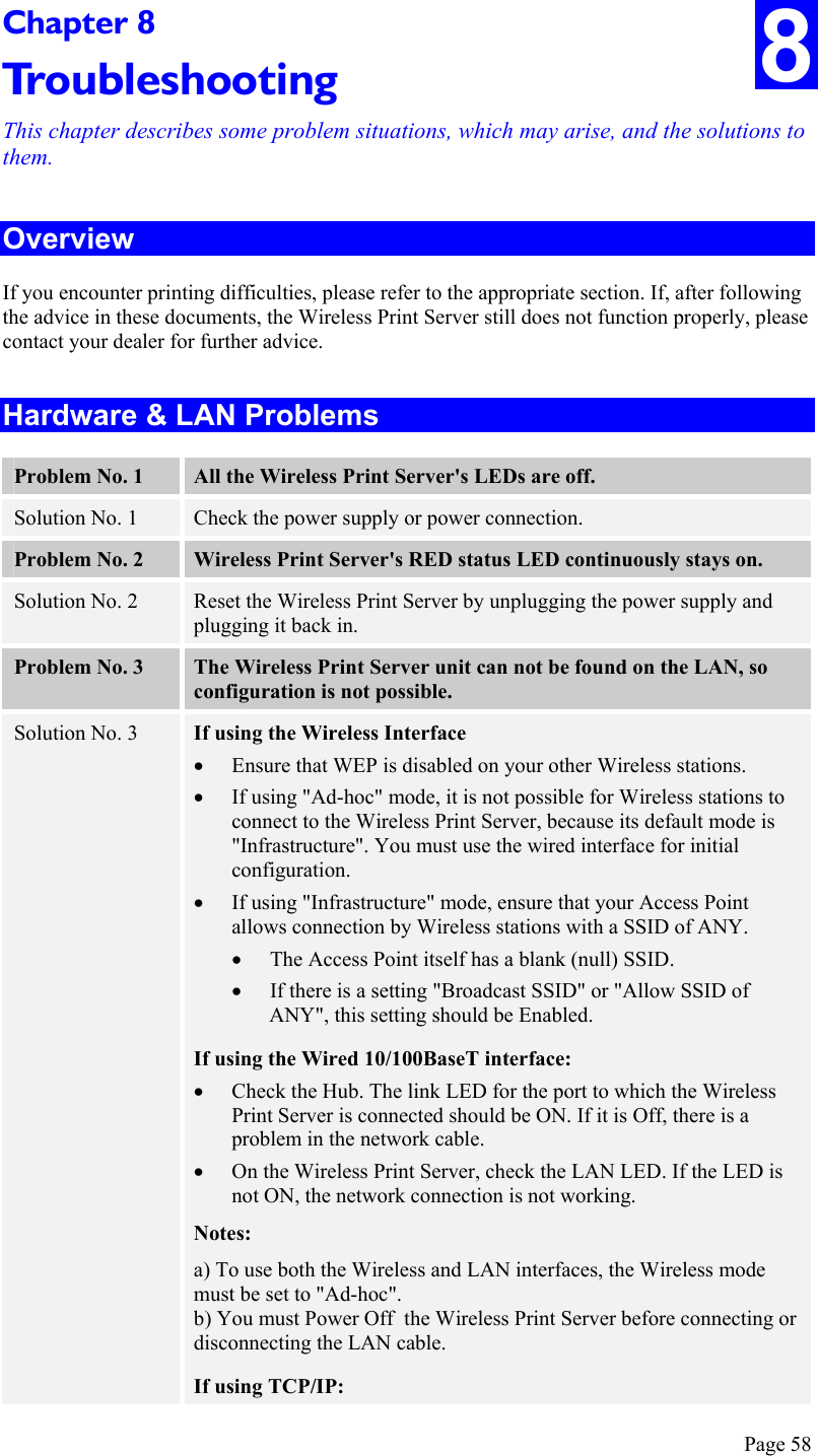
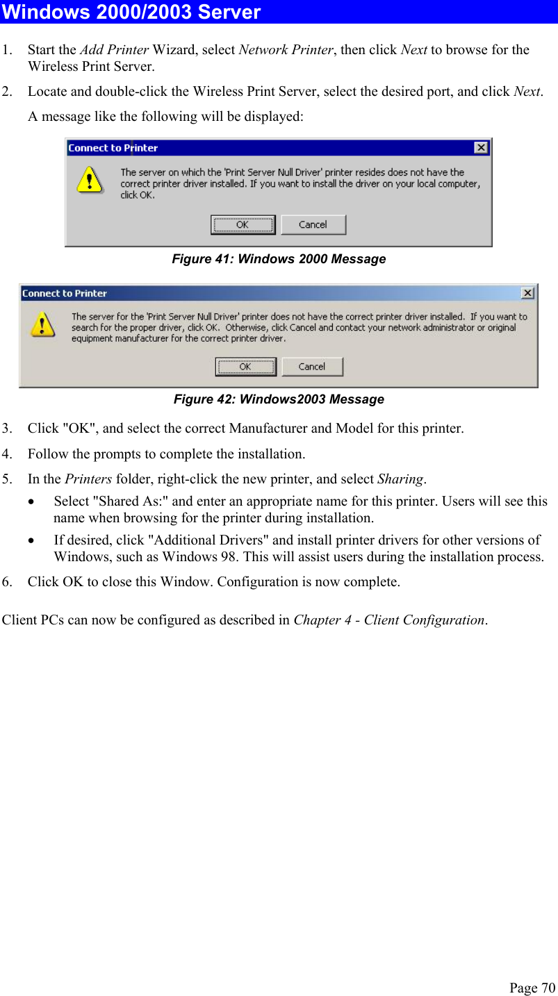
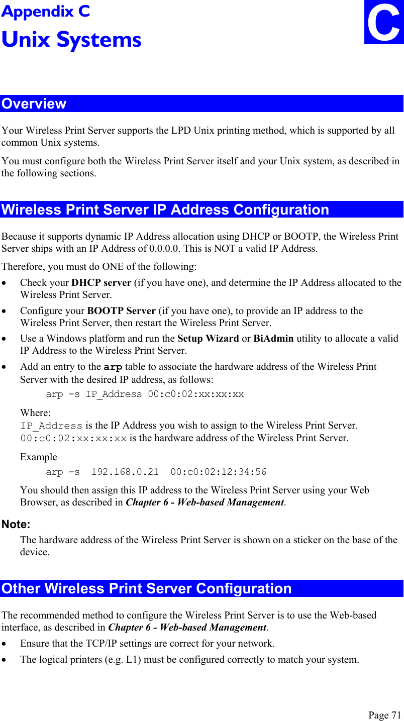
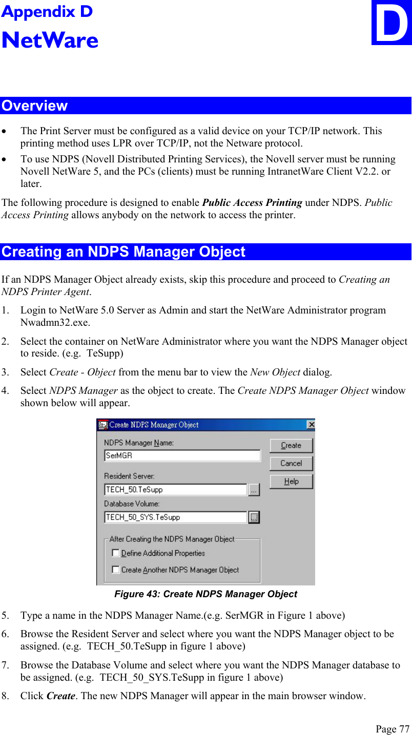
![LPD on System V Before beginning LPD Setup, ensure that an IP Address has been assigned to the Wireless Print Server. Keep the following points in mind: The remote host name is the name of the Wireless Print Server. The remote printer name is the print queue name for the Logical Printer. Logical printers also need to be configured on the Wireless Print Server itself. If your UNIX asks for the LPD type, be sure to identify the service type as BSD. The Wireless Print Server’s LPD protocol meets BSD system standards. In the sample commands shown, printer_name is the name of the Print Queue serviced by the Wireless Print Server, and Spooler_directory is the name of the directory, which is used to spool the print jobs. Procedure Action Sample Command Stop Print Services /usr/lib/lpshut Add a System Printer /usr/lib/lpadmin -p printer_name -v /dev/null Restart the Print Services /usr/lib/lpsched Enable printing to the new printer device enable printer_name Start accepting jobs for the new printer device accept printer_name Create a spooling directory mkdir /usr/spool/Spooler_directory Make spooling daemon the owner of this directory chown daemon /usr/spool/Spooler_directory Create read/write permissions chmod 775 /usr/spool/Spooler_directory Give permissions to LPD processes. chgrp daemon /usr/spool/Spooler_directory Add remote printer(s) See following section Adding Remote Printers A remote printer is added by inserting the following line in the /etc/printcap file. The entry is really one line, but can be entered as shown. Use a TAB character where shown. Printer_name|Remote_Printer_Alias:\ [TAB] :lp=:\ [TAB] :rm=PS_NAME:\ [TAB] :rp=Logical_Printer_name:\ [TAB] :sd=Spooler_directory:\ [TAB] :mx#0: Page 73](https://usermanual.wiki/ARRIS/WPS870G.Users-Manual-Part-2/User-Guide-419133-Page-36.png)
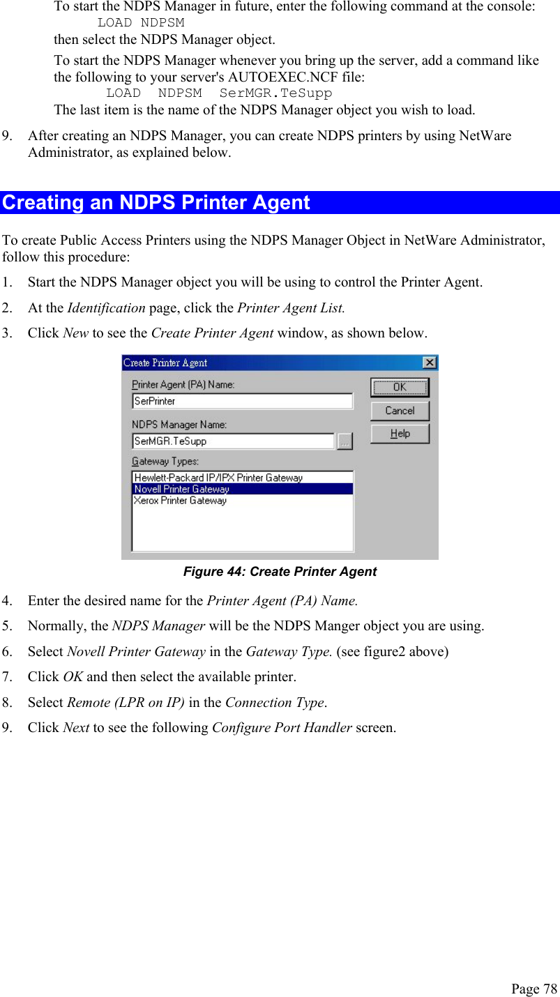
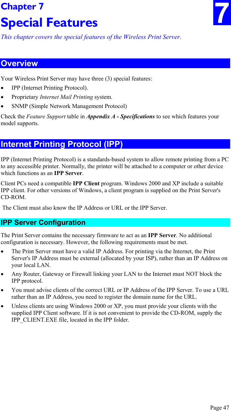
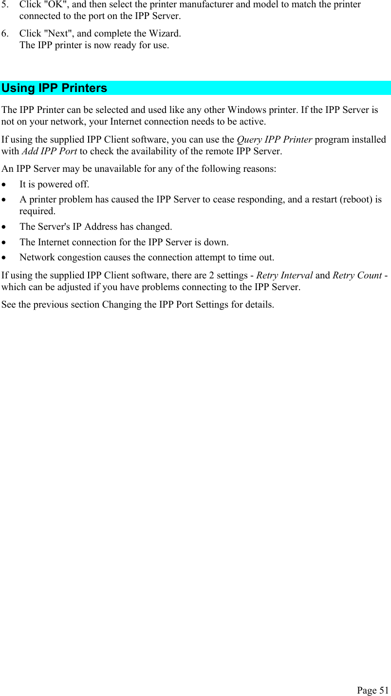
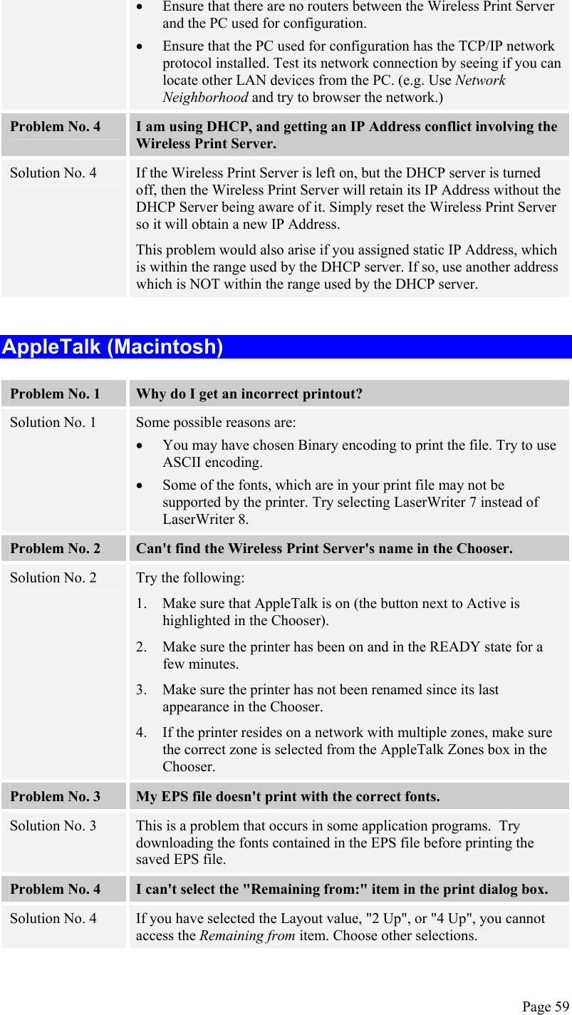
![Where: Printer_name is the Print Queue name used to store jobs for the corresponding logical printer. PS_NAME is the Wireless Print Server name defined in /etc/hosts. Logical_Printer_name is the logical printer name on the Wireless Print Server. (e.g. L1) Spooler_directory is the directory you created in Step 6. Example: Marketing|RP1_PS123456:\ [TAB] :lp=:\ [TAB] :rm=PS_Rm203:\ [TAB] :rp=L1:\ [TAB] :sd=/usr/spool/Marketing:\ [TAB] :mx#0: Repeat this process for each Logical Printer/Print Queue combination that you wish to create. LPD on Linux If using the command line, the procedure is the same as for System V. (above) On recent Linux distributions, you can use the graphical X-windows interface instead of the command line. The procedure is described below, but may vary according to your version of Linux. 1. Start your X-windows shell. 2. Select Control Panel, then Printer Configuration. 3. Select Add. For the printer type, select Remote Unix (lpd) Queue. 4. Use the following data to complete the resulting dialog. Field Data Name Enter a name for this printer Spool Directory /var/spool/lpd/name_of_printer File Limit 0 (no limit) Remote Host Name or IP Address of Wireless Print Server e.g. SC3000014 Note: host file entry is required to use the name instead of IP Address Remote Queue Ln Where n is the Logical Printer number By default, L1 is port 1, and L2 is port 2 if the Print Server has 2 ports. 5. Save this data, and exit the Printer Configuration. Configuration is now completed, and the printer is now available for use. Page 74](https://usermanual.wiki/ARRIS/WPS870G.Users-Manual-Part-2/User-Guide-419133-Page-37.png)
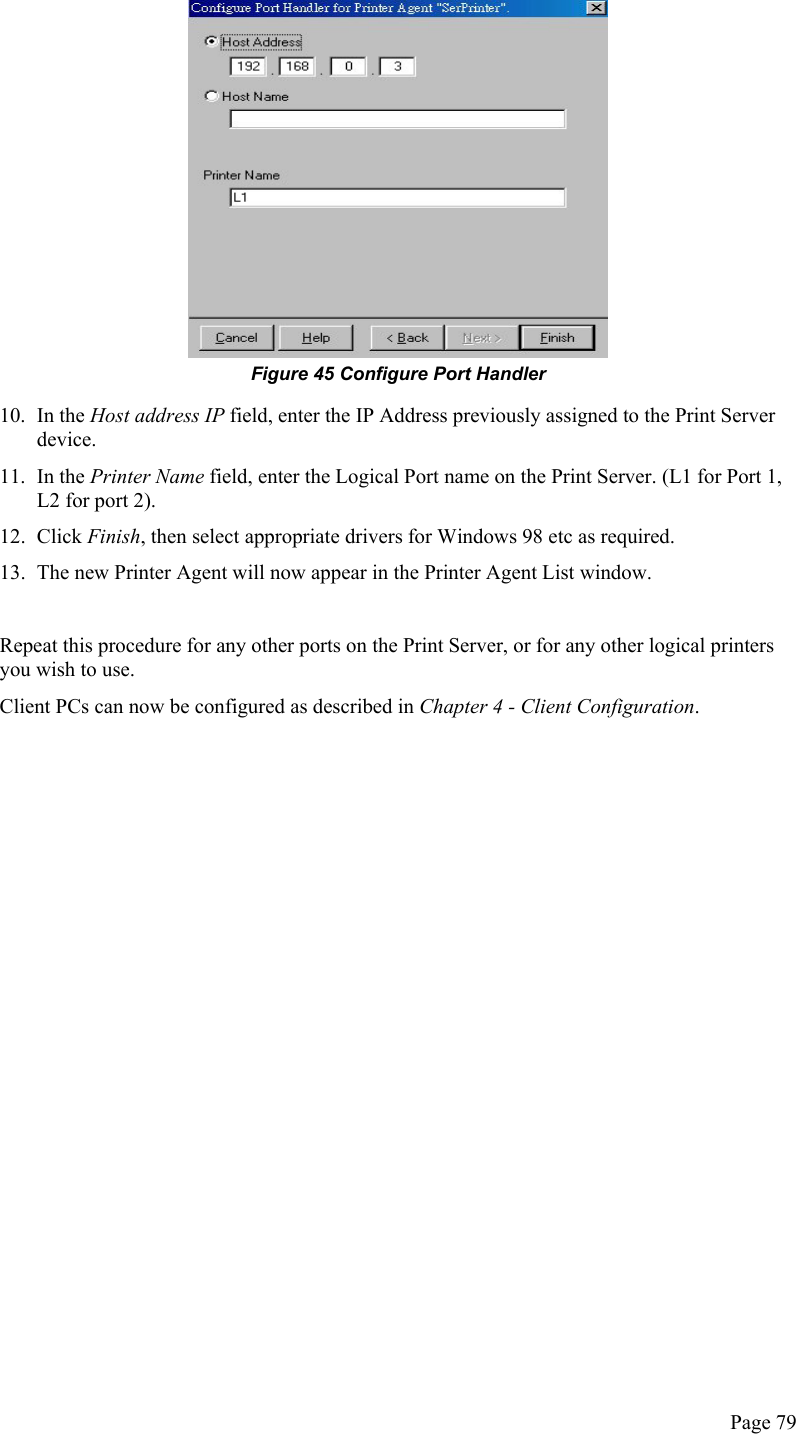
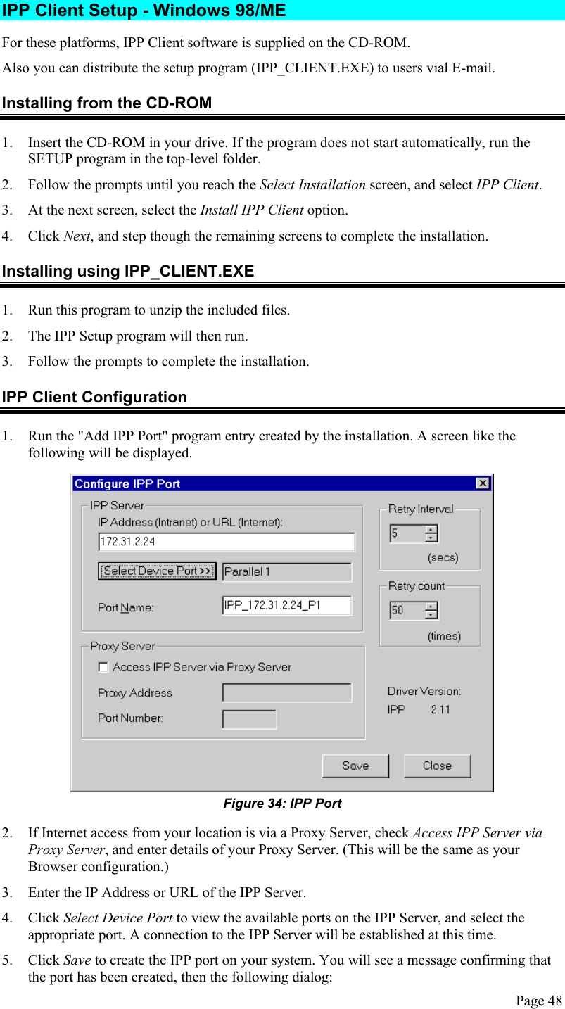
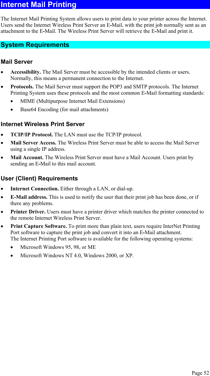
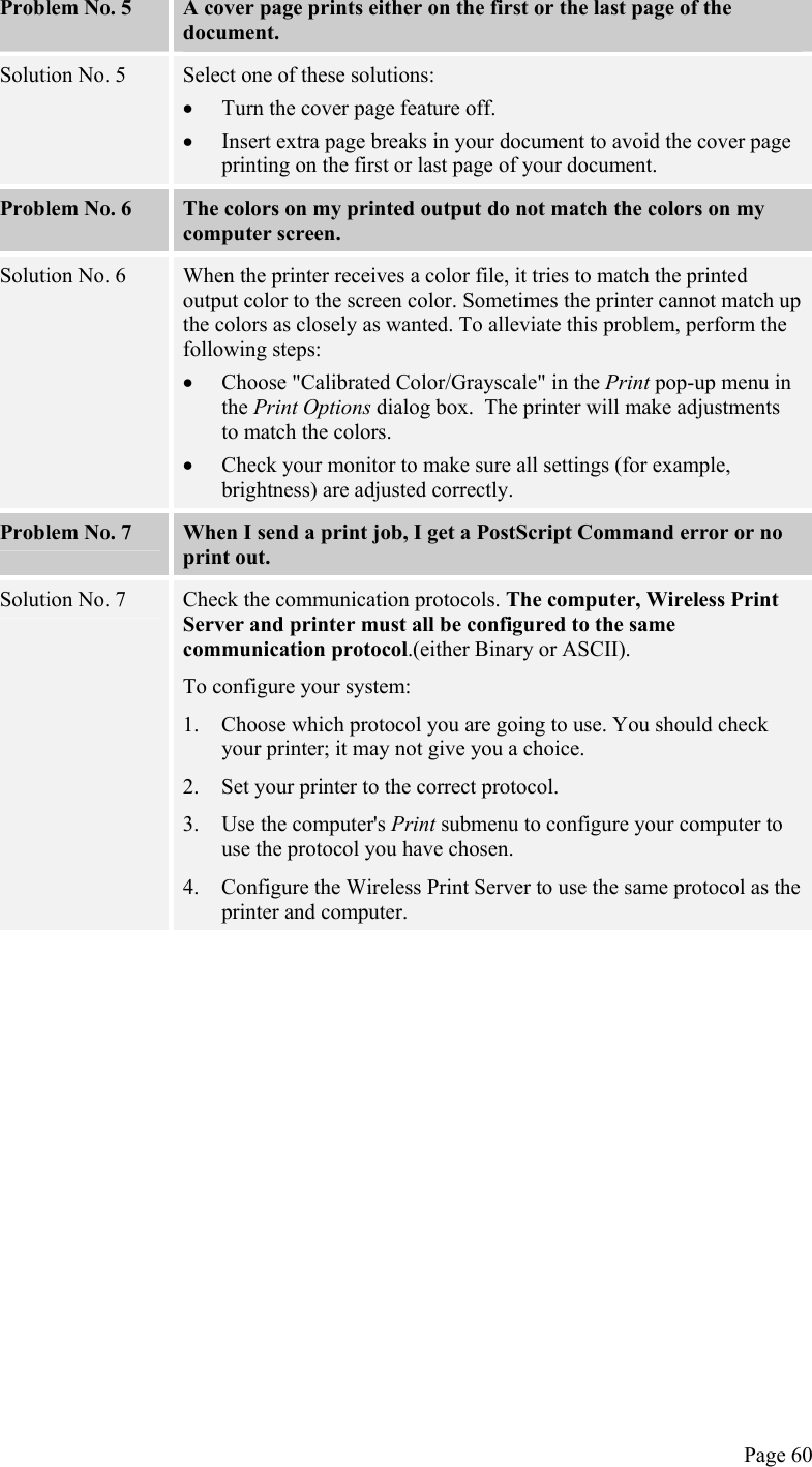
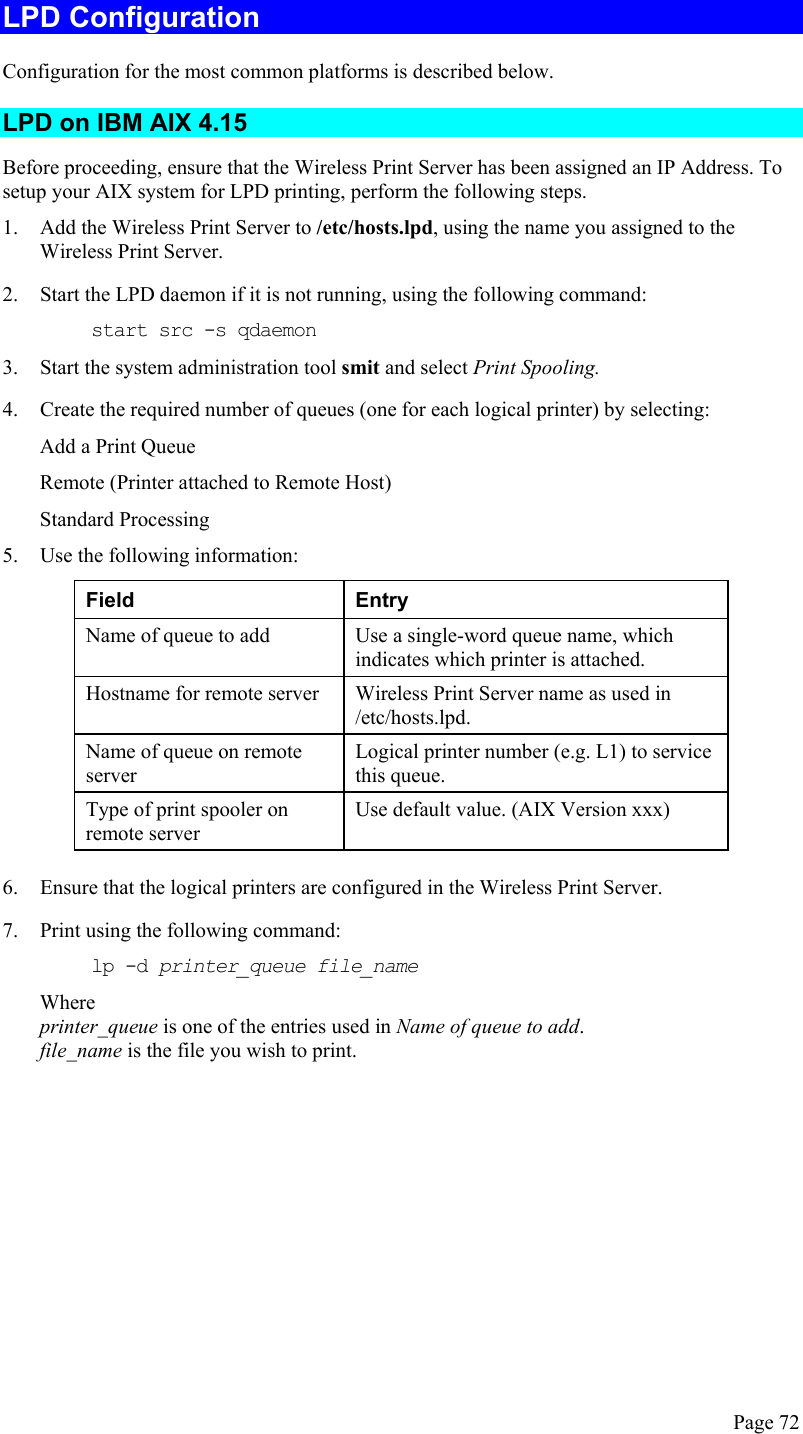
![LPD on BSD Before continuing, ensure that an IP Address has been assigned to the Wireless Print Server. Remember the following: The remote host name is the name of the Wireless Print Server. The remote printer name is the logical printer (e.g. L1) on the Wireless Print Server. If asked for the LPD type, enter the service type as BSD. In the sample commands shown, printer_name is the Print Queue serviced by the logical printer on the Wireless Print Server, and Spooler_dir is the name of the directory, which is used to spool the print jobs. Procedure Action Sample Command Create a spooling directory mkdir /usr/spool/Spooler_dir Set spooling daemon as owner of this directory chown daemon /usr/spool/Spooler_dir Create read/write permissions chmod 775 /usr/spool/Spooler_dir Give permissions to LPD processes chgrp daemon /usr/spool/Spooler_dir Add remote printer(s) See below Start lpc print mechanism lpc start printer_name Adding Remote Printers A remote printer is added by inserting the following line in the /etc/printcap file. The entry is really one line, but can be entered as shown. Use a TAB character where shown. Printer_name|Remote_Printer_Alias:\ [TAB] :lp=:\ [TAB] :rm=PS_NAME:\ [TAB] :rp=Logical_Printer_name:\ [TAB] :sd=Spooler_directory:\ [TAB] :mx#0: Where: Printer_name is the Print Queue name used to store jobs for the corresponding logical printer. PS_NAME is the Wireless Print Server name defined in /etc/hosts. Logical_Printer_name is the logical printer name on the Wireless Print Server. (e.g. L1) Spooler_directory is the directory you created in Step 6. Page 75](https://usermanual.wiki/ARRIS/WPS870G.Users-Manual-Part-2/User-Guide-419133-Page-38.png)
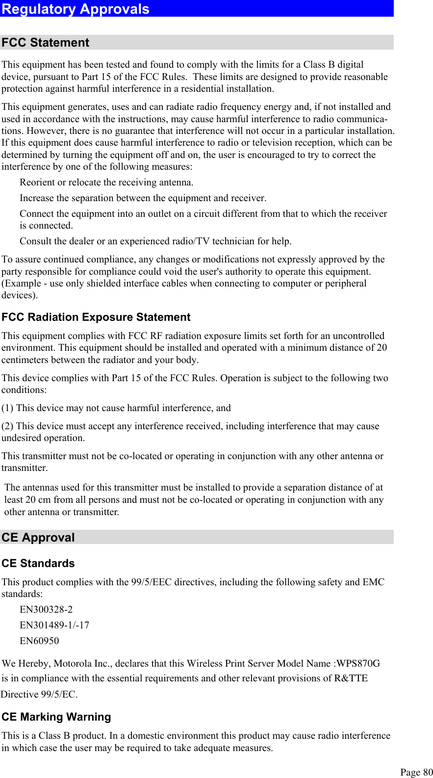
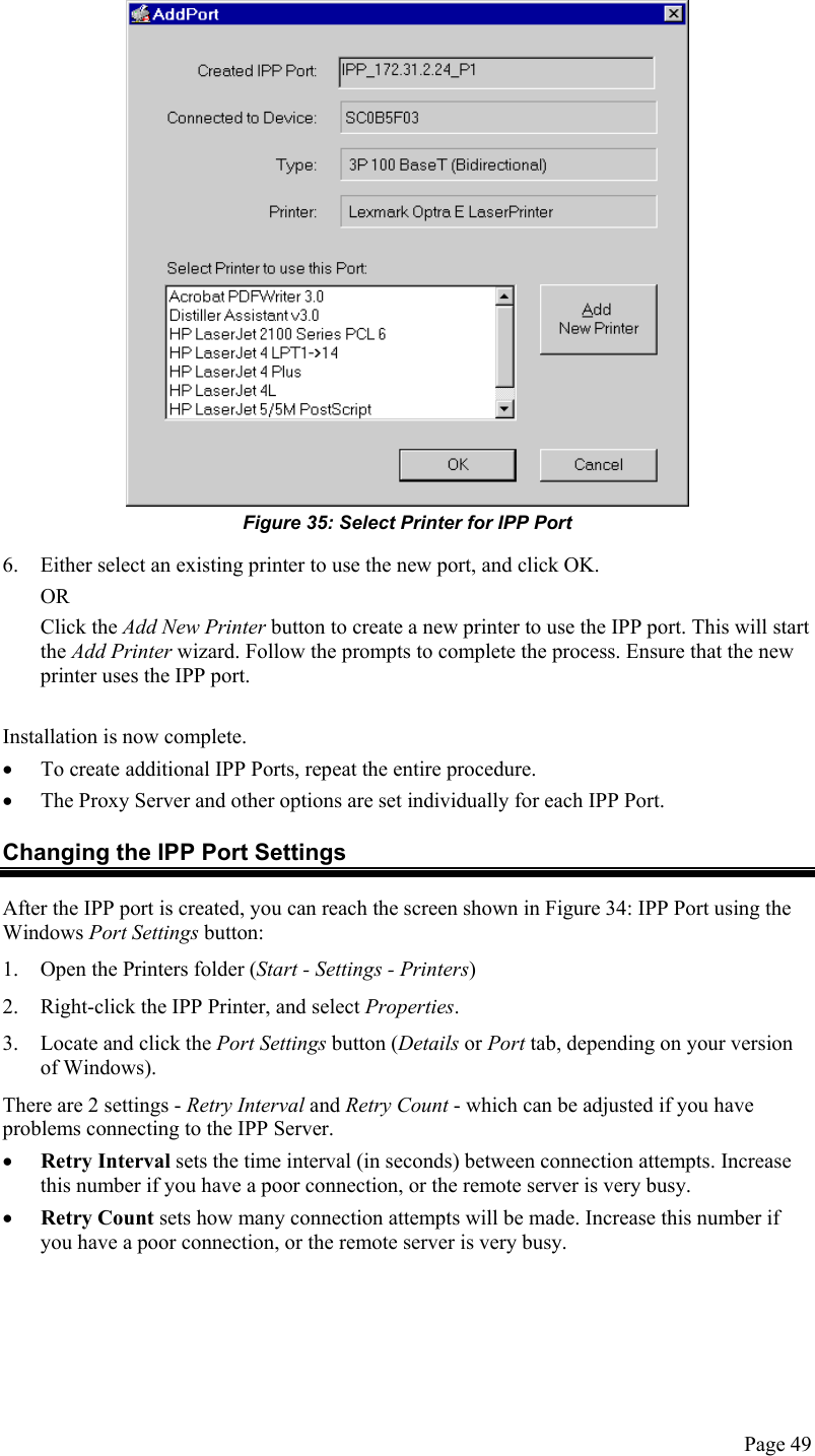
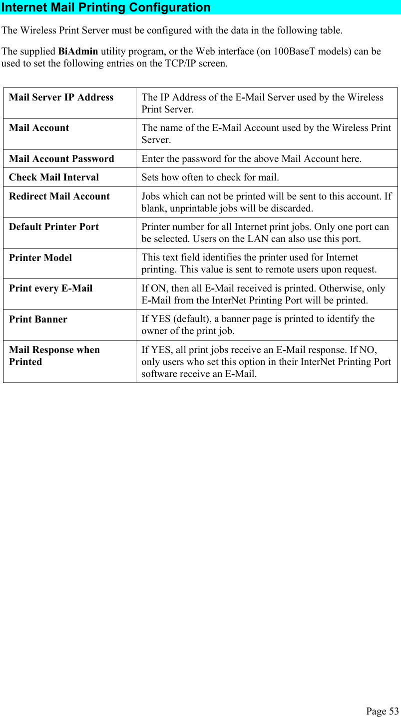
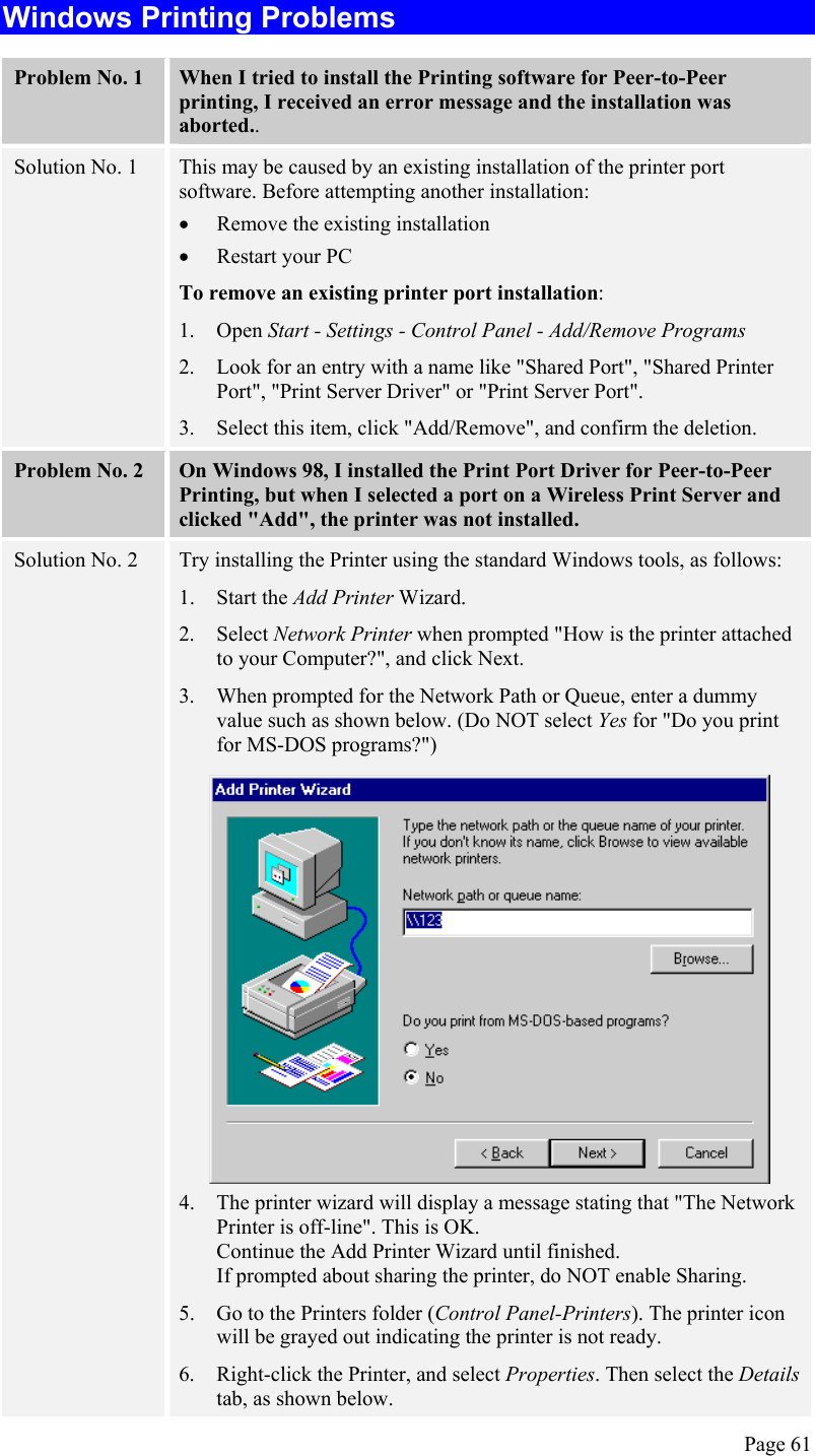
![Example: Marketing|RP1_PS123456:\ [TAB] :lp=:\ [TAB] :rm=PS_Rm203:\ [TAB] :rp=L1:\ [TAB] :sd=/usr/spool/Marketing:\ [TAB] :mx#0: Repeat this process for each Logical Printer/Print Queue combination that you wish to create. Printing using LPD For LPD printing instructions, refer to your UNIX manual. The following example is for a BSD system: lpr -P printer_name filename Where: printer_name is the name of the Print Queue defined on the Unix host. filename is the name of the file you wish to print. Example: lpr -P Marketing /etc/hosts In the above example, the /etc/hosts file is sent to the printer queue Marketing. It will then be sent to the logical printer associated with this queue. Page 76](https://usermanual.wiki/ARRIS/WPS870G.Users-Manual-Part-2/User-Guide-419133-Page-39.png)