ARRIS WR2100 802.11N Wireless repeater 2.4GHz 2x2:2 MIMO User Manual WR2100
ARRIS Group, Inc. 802.11N Wireless repeater 2.4GHz 2x2:2 MIMO WR2100
ARRIS >
WR2100 User manual
i
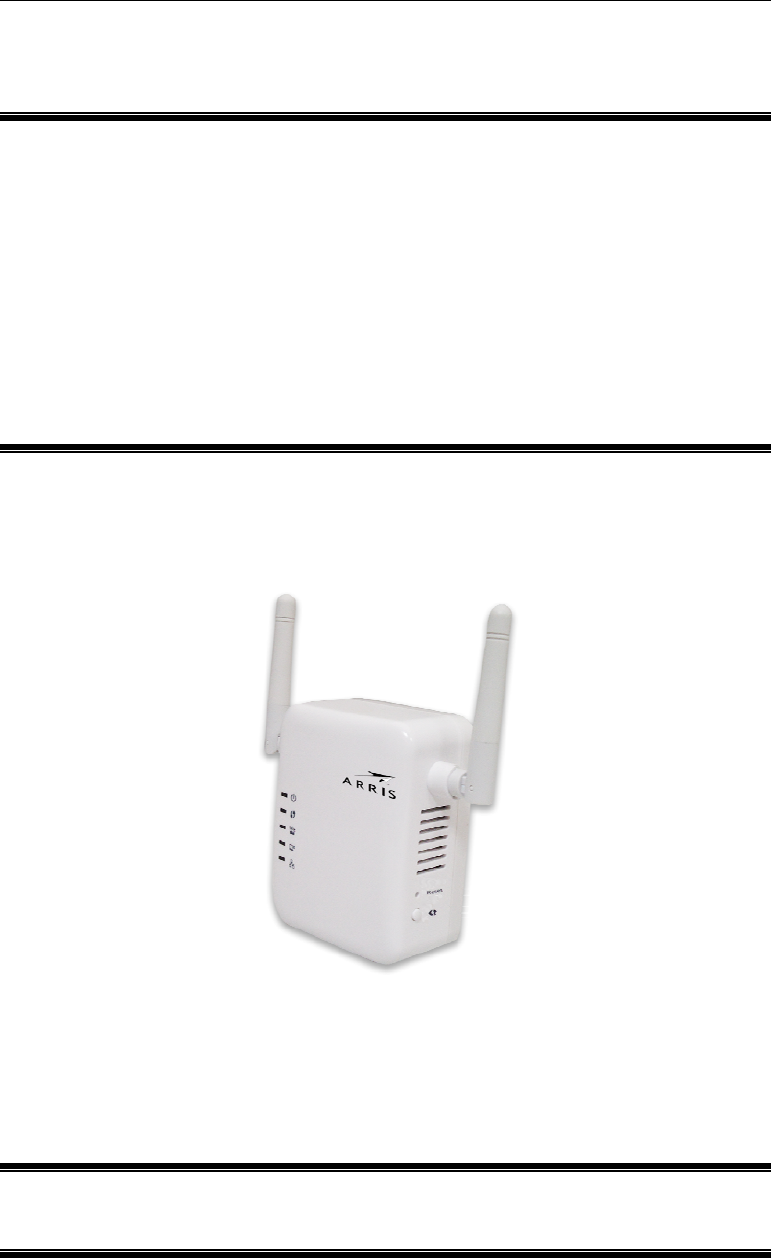
WR2100
802.11N Wireless
repeater 2.4GHz
2x2:2 MIMO
Quick Installation Guide
P/N: Document Version: 1.0
ii
Copyright 2012. All Rights Reserved.
All trademarks and trade names are the properties of their respective
owners
Package Contents
The following items should be included: If any of these items are
damaged or missing, please contact your service provider immediately.
1. The WR2100 Unit
2. Quick Installation Guide

1
Chapter 1
Introduction
This Chapter provides details of the WR2100's features,
components and capabilities.
Overview
This WR2100 is designed to enhance the connectivity between the
Wireless Access Point and wireless client device (ex. IP camera) while
increasing the coverage of the existing wireless network. With its easy
setup operation, this high-speed 802.11n device works seamlessly with
most routers and access points.
Features
Easy Setup. Use your WEB browser from anywhere on the LAN for
configuration.
Wireless Features
Supports 11n Wireless Stations: The 802.11n standard provides
for backward compatibility with the 802.11b standard, so 802.11n,
802.11b and 802.11g wireless stations can be used simultaneously.
WPS Support. WPS (Wi-Fi Protected Setup) can simplify the
process of connecting any device to the wireless network by using
the press button configuration on the device.
Security Support: Full WEP (64/128 Bit), WPA and WPA2
Personal standards are supported on the wireless interface, allowing
advanced encryption of wireless data.
1
2
Chapter 2
Basic Setup
This Chapter provides details on how to setup the WR2100.
System Requirement
To use the wireless interface on the wireless model, other wireless
devices must be compliant with the IEEE802.11b, IEEE802.11g or
IEEE 802.11n specifications. All wireless stations must use
compatible settings.
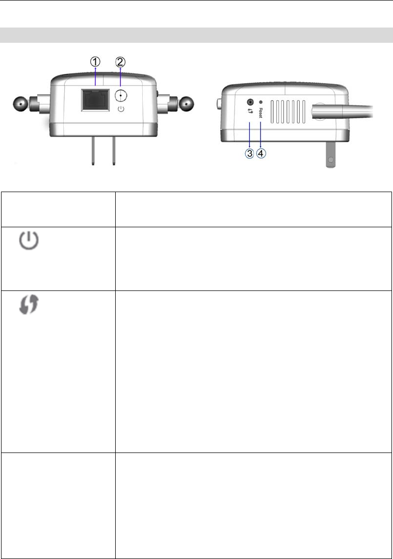
Physical Details
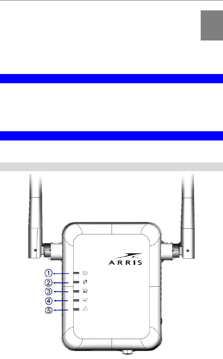
Front Panel
Figure 1: Front Panel
2
3
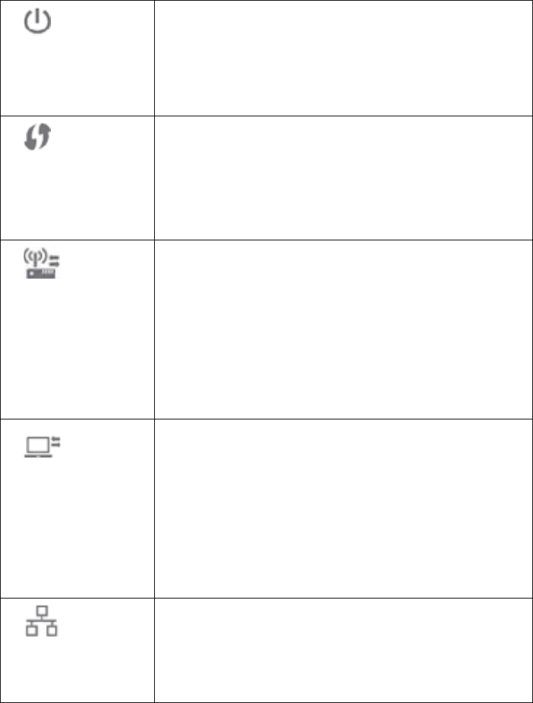
1.
Power LED
(Green/Amber)
On (Green) - Power on.
Off - No power.
Blinking - The Power LED will blink during start
up. This will take 15 to 20 seconds.
On (Amber) - System failure.
2.
WPS LED (Green)
On (Green) - When WPS button is pressed, the
LED will be on for 2 minutes.
Off - WPS feature is not in use.
Slow Blinking (Green) - WPS is activating.
Quick Blinking (Green) - WPS failure.
3.
AP/Repeater LED
(Green/Red)
On (Green) - AP connection is available and the
signal strength is good.
Off - AP connection is not established.
On (Amber) - The signal strength is normal.
On (Red) - The signal strength is poor.
Note: if the LED indicator shows red, you need
to install the device in a better location.
4.
Repeater/Client
LED (Green/Red)
On (Green) - Client connection is available and
the signal strength is good.
Off - Client connection is not established.
On (Amber) - The signal strength is normal.
On (Red) - The signal strength is poor.
Note: if the LED indicator shows red, you need
to install the device in a better location.
5.
Ethernet LED
(Green)
On (Green) - LAN connection is available.
Off - LAN is not connected.
Blinking (Green) - Data is being transmitted or
received via the LAN connection.
4
Side Panel
Figure 2: Side Panel
1. LAN port Use a standard LAN cable to connect your
WR2100 to a PC.
2.
Power On/Off
Switch
Press this button to turn on/off the WR2100.
3.
WPS Button
Press the WPS button on the device and on your
other wireless device to perform WPS function
that easily creates an encryption-secured
wireless connection automatically.
AP Connection. When pressed and held
over 3 seconds, the WR2100 will perform
WPS function with the AP.
Client Connection. When pressed and
released (less then 3 seconds), the WR2100
will perform WPS function with the client
devices.
4. Reset Button This button is recessed; A pin or paper clip can
be used to depress it. It can be activated at any
time the WR2100 is in the "ready" mode.
Reset to manufacturer default values and
reboot. When pressed and held over 10
seconds, the settings of the WR2100 will be
set to their default values.
5
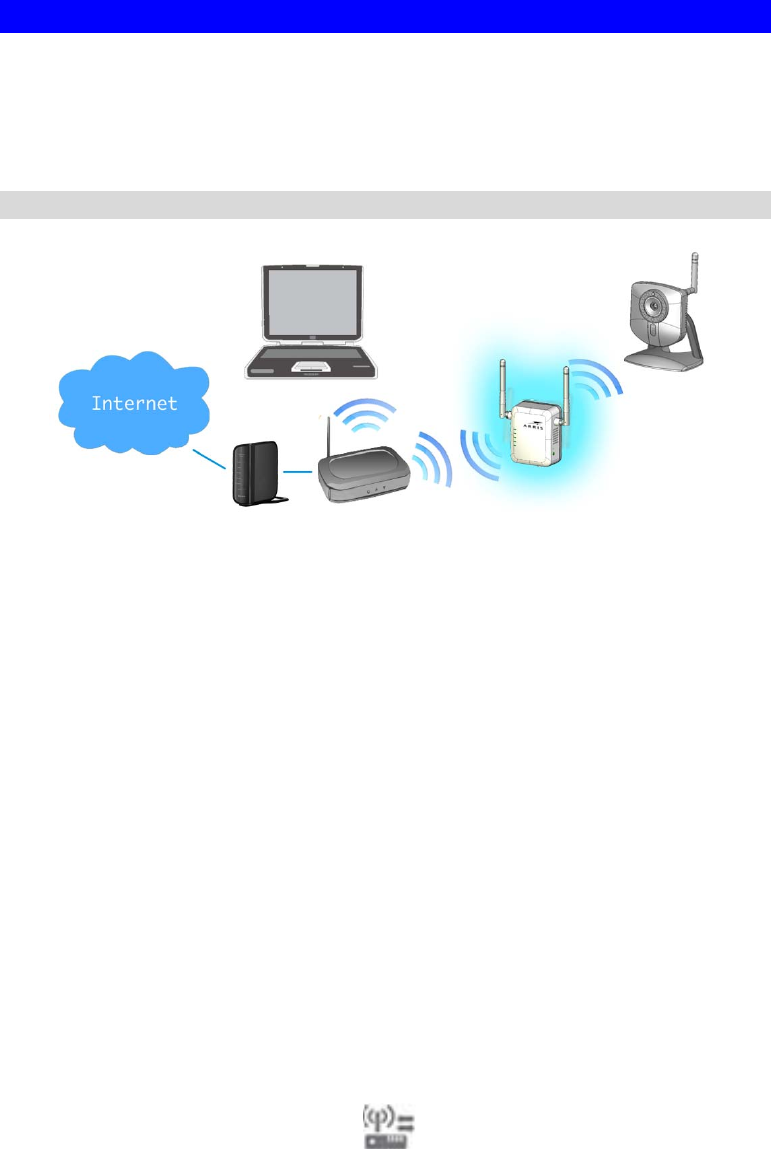
Setup the WR2100
The installation allows the WR2100 to directly connect to a wireless
router (or Wireless Access Point). You can extend the range of your
wireless network, or to add an extension of your network without
running cables.
Configured without a PC - Using WPS
Step 1: Locate the WR2100 near the Wireless Access Point while doing
the configuration.
Step 2: Make sure the Wireless Access Point is on and working
properly.
Step 3: Plug the WR2100 into the power outlet and press the Power
button to power it on.
Step 4: Wait for the Power LED to remain on, the WR2100 is now
ready for use.
Step 5: Press the WPS button on the Wireless Access Point and make
sure the Wireless Access Point is in WPS mode. (The LED on the AP
will blink and active for 2 minutes.)
Step 6: Press and hold the WPS button on the WR2100 for more than 3
seconds. The WPS LED on the device will start blinking for 2 minutes.
The WR2100 will automatically associate to the Wireless Access Point
with the strongest signal and make connection. Make sure to press the
button within 120 seconds (2 minutes) after pressing the Wireless
Access Point WPS button.
Step 7: The connection of the WR2100 and Wireless Access Point is
successfully established after the LED remains on.
6
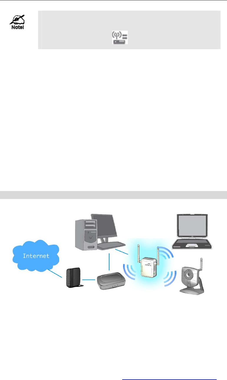
Locate the WR2100 in another place for better
wireless reception and performance If the signal
strength is weak (the color is red).
Step 8: Now you can select a suitable location for the WR2100. It's
preferable to place the device near the center of your wireless coverage
area. Check the LED color and make sure it’s not red.
Step 9: Power on the client device (ex. IP Camera) and make sure it is
in wireless mode.
Step 10: Press the WPS button (less than 3 seconds) of the WR2100.
The WPS LED will start blinking for 2 minutes. Then press the WPS
button on the client device. Make sure to press the button within 120
seconds (2 minutes) after pressing the WR2100 WPS button.
Step 11: Wait for the WPS LEDs to be solid on both WR2100 and the
client device. Check the LED color again.
Step 12: Now the client device can access to the wireless network.
Configured with a PC
Step 1: Make sure the Wireless Access Point is on and working
properly.
Step 2: Plug the WR2100 into the power outlet and press the Power
button to power it on.
Step 3: Wait for the Power LED to remain on; the WR2100 is now
ready for use.
Step 4: Connect the Ethernet cable to the WR2100 and the PC.
Step 5: Launch the browser and enter http://www.mywifirepeater.net/ in
the Address box.
7
Step 6: You will then be prompted for a username and password. If
using the default values, enter admin for the username, and password
for the password.
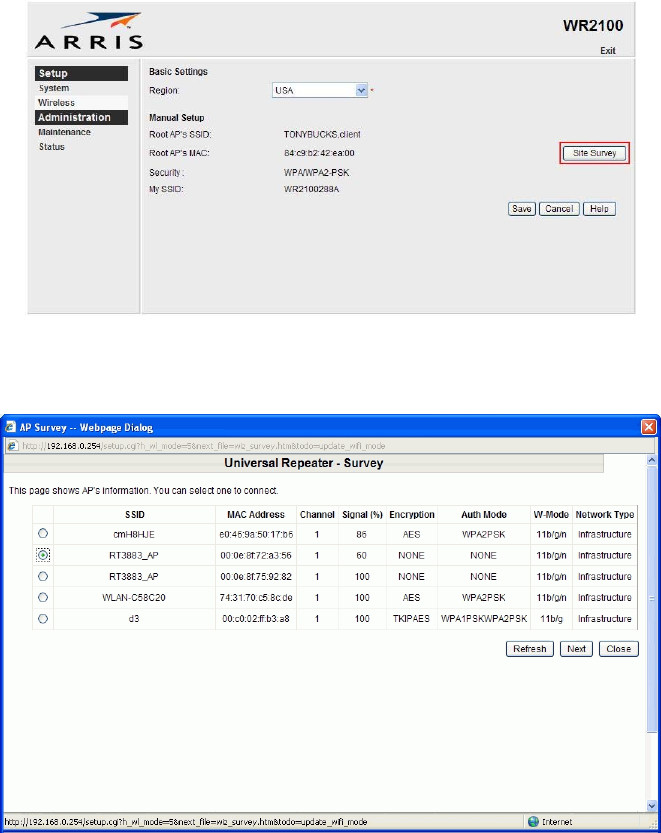
Step 7: Choose the Wireless page and click “Site Survey” button. The
WR2100 will start to search the existing wireless network.
Step 8: Select the desired SSID that you want to connect to. Click Next.
8
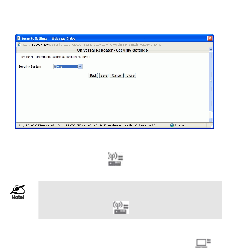
Step 9: The Security Settings screen will be prompted automatically if
the security is on. Enter the required encryption keys. Click Save.
Step 10: The connection of the WR2100 and Wireless Access Point is
successfully established after the LED remains on.
Locate the WR2100 in another place for better
wireless reception and performance If the signal
strength is weak (the color is red).
Step 11: Configure the client device (Ex. IP Camera) with the same
SSID and encryption keys.
Step 12: The connection is successfully established after the LED
remains on. Check the LED color. If it is red, then the device needs to
be relocated.
Step 13: Now the client device can access to the wireless network.

9
Appendix A
Specifications
WR2100
Model 802.11N Wireless repeater 2.4GHz 2x2:2 MIMO
Dimensions 67mm (W) x 85mm (H) x 36mm (D)
Operating
Temperature 0 C to 40 C
Antenna External antenna x 2
Storage
Temperature -20 C to 85 C
Network Interface 1 Ethernet 10/100BaseT (RJ45) LAN connection
Wireless interface 802.11b: 20 dBm@11Mbps
802.11g: 18 dBm@54Mbps
802.11n: 18 dBm@130Mbps and 270Mbps
LEDs 5
Power 100~240V AC (Build-in Power)
Regulatory Approvals
FCC Statement
This equipment has been tested and found to comply with the limits for
a Class B digital device, pursuant to part 15 of the FCC rules. These
limits are designed to provide reasonable protection against harmful
interference in a residential installation. This equipment generates, uses
and can radiate radio frequency energy and, if not installed and used in
accordance with the instructions, may cause harmful interference to
radio communications. However, there is no guarantee that interference
will not occur in a particular installation. If this equipment does cause
harmful interference to radio or television reception, which can be
determined by turning the equipment off and on, the user is encouraged
to try to correct the interference by one or more of the following
measures:
A

10
-Reorient or relocate the receiving antenna.
-Increase the separation between the equipment and receiver.
-Connect the equipment into an outlet on a circuit different from that
to which the receiver is connected.
-Consult the dealer or an experienced radio/TV technician for help.
To assure continued compliance, any changes or modifications not
expressly approved by the party responsible for compliance could void
the user's authority to operate this equipment. (Example - use only
shielded interface cables when connecting to computer or peripheral
devices).
FCC Radiation Exposure Statement
This equipment complies with FCC RF radiation exposure limits set
forth for an uncontrolled environment. This equipment should be
installed and operated with a minimum distance of 20 centimeters
between the radiator and your body.
This device complies with Part 15 of the FCC Rules. Operation is
subject to the following two conditions:
(1) This device may not cause harmful interference, and
(2) This device must accept any interference received, including
interference that may cause undesired operation.
This transmitter must not be co-located or operating in conjunction with
any other antenna or transmitter.
You are cautioned that changes or modifications not expressly
approved by the party responsible for compliance could void your
authority to operate the equipment.