ARRIS WR850GV2 Wireless Broadband Router User Manual WR850G
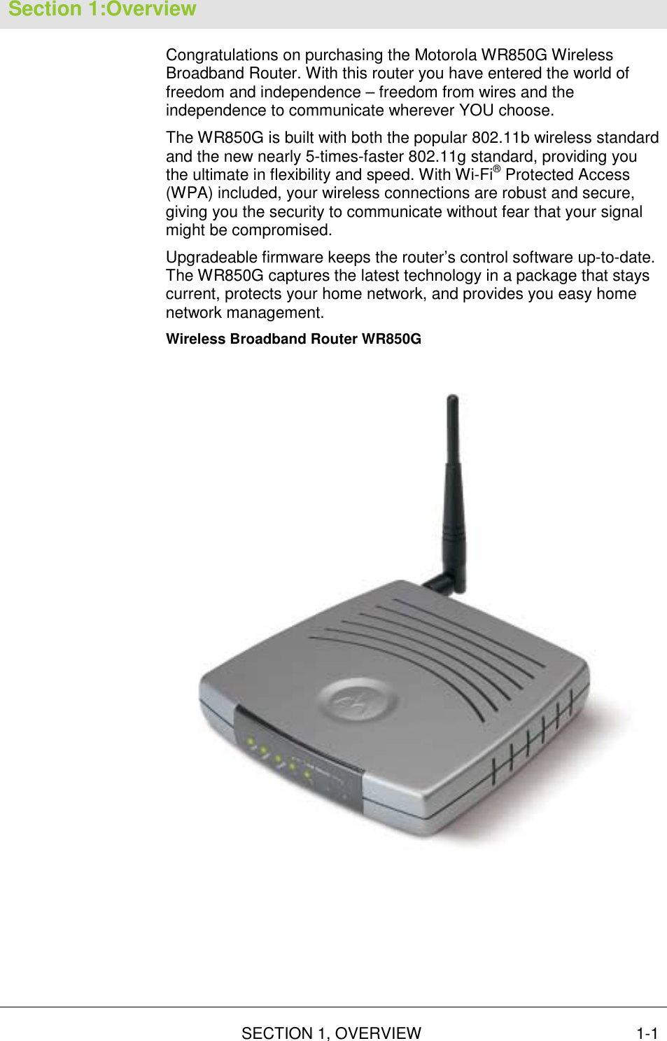
ARRIS Group, Inc. Wireless Broadband Router WR850G
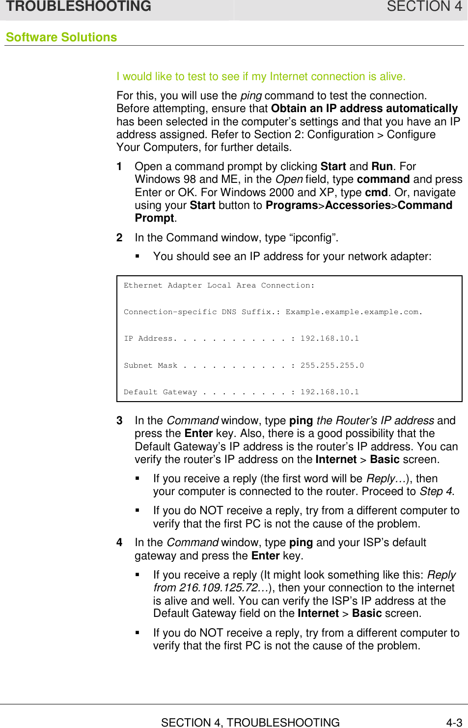
UserManual.wiki
>
ARRIS
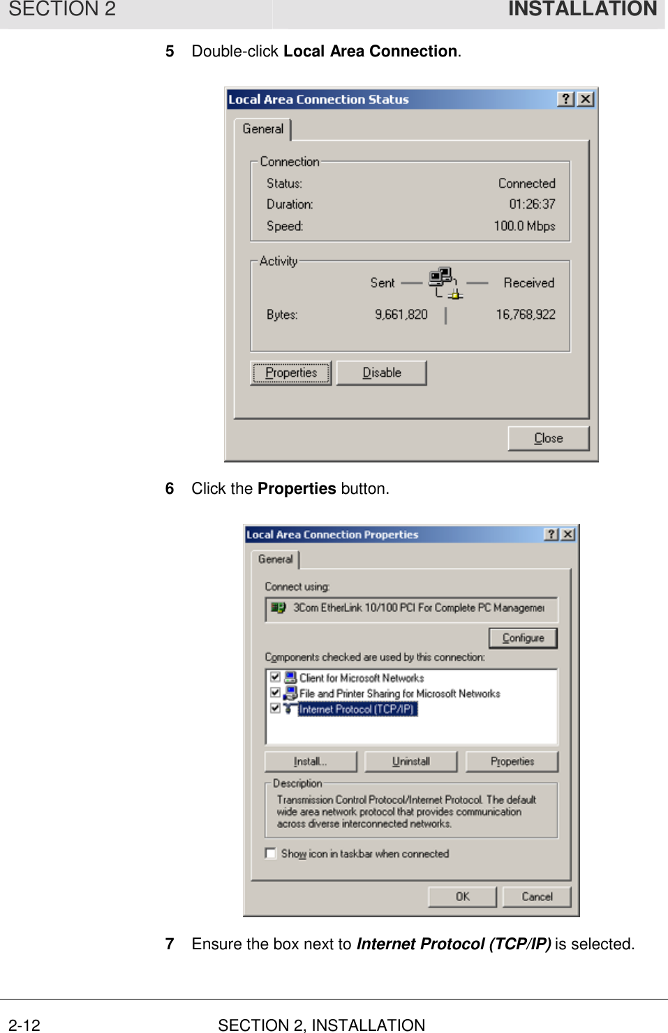
>
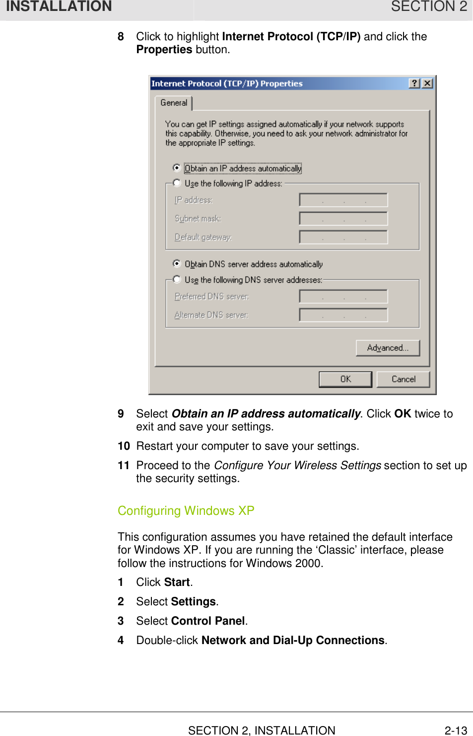
WR850GV2 User Manual
User Manual
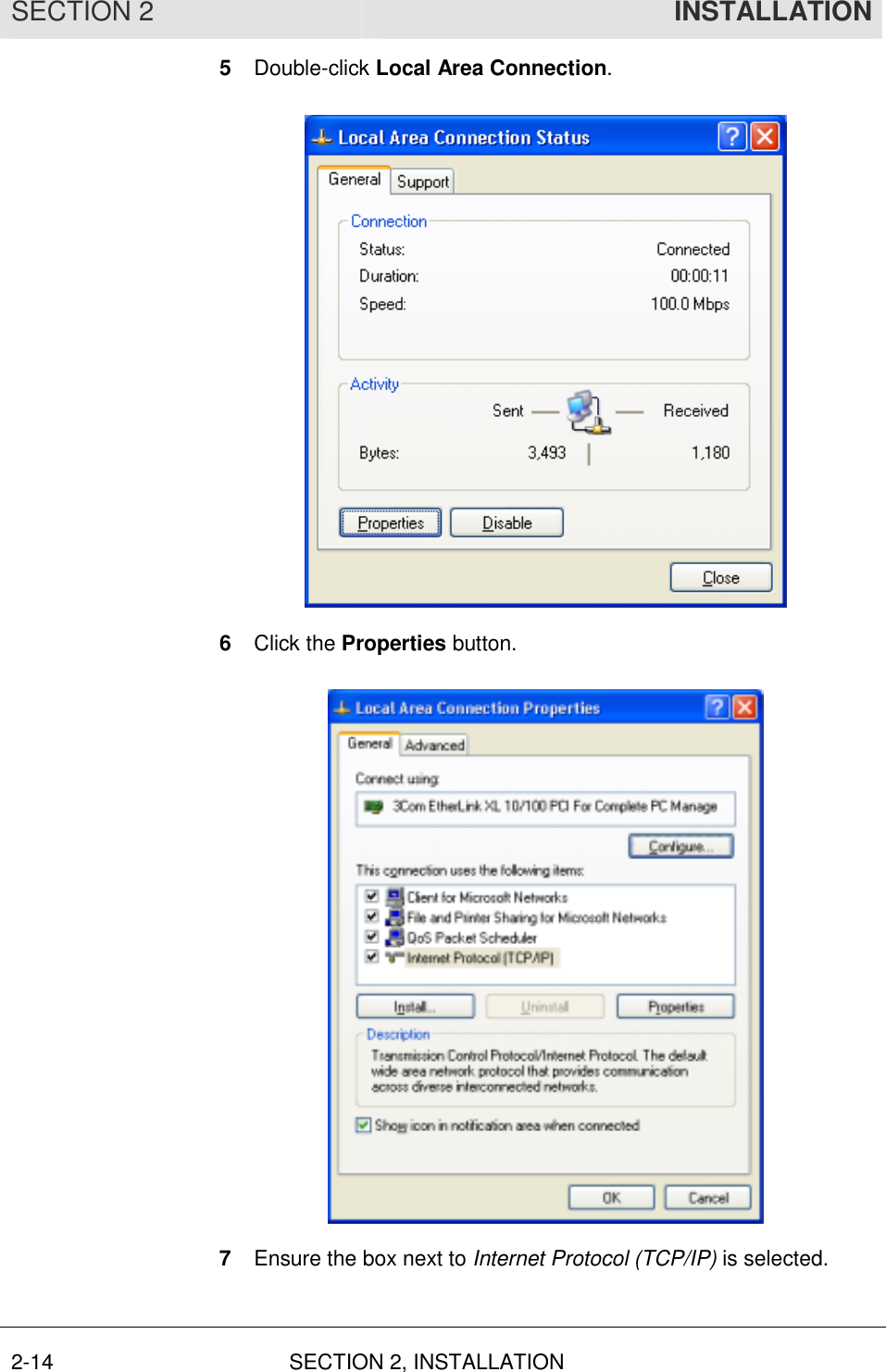
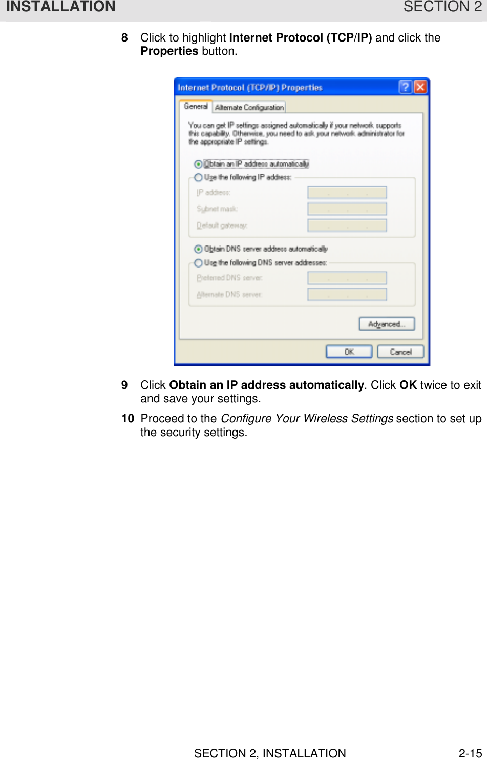
Navigation menu
Upload a User Manual
Namespaces
Wiki Guide
HTML
PDF
Info
Views
User Manual
Discussion / Help
Navigation
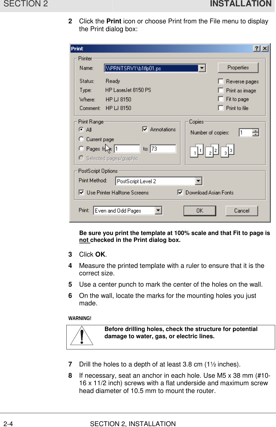
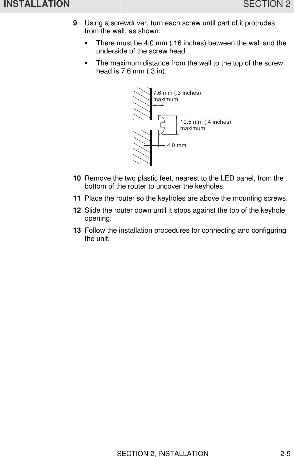
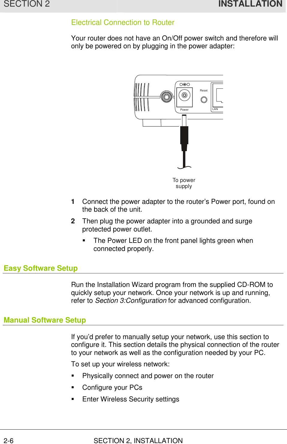
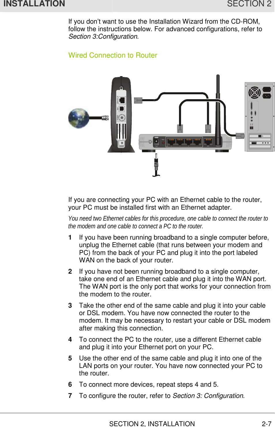
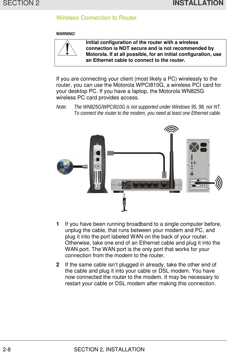
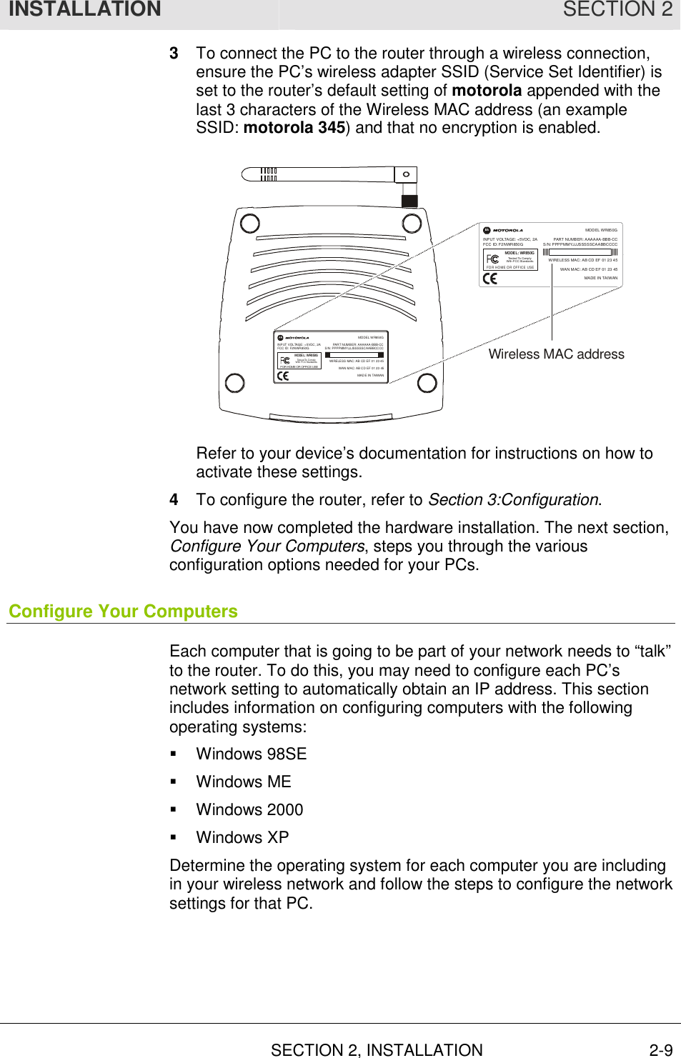
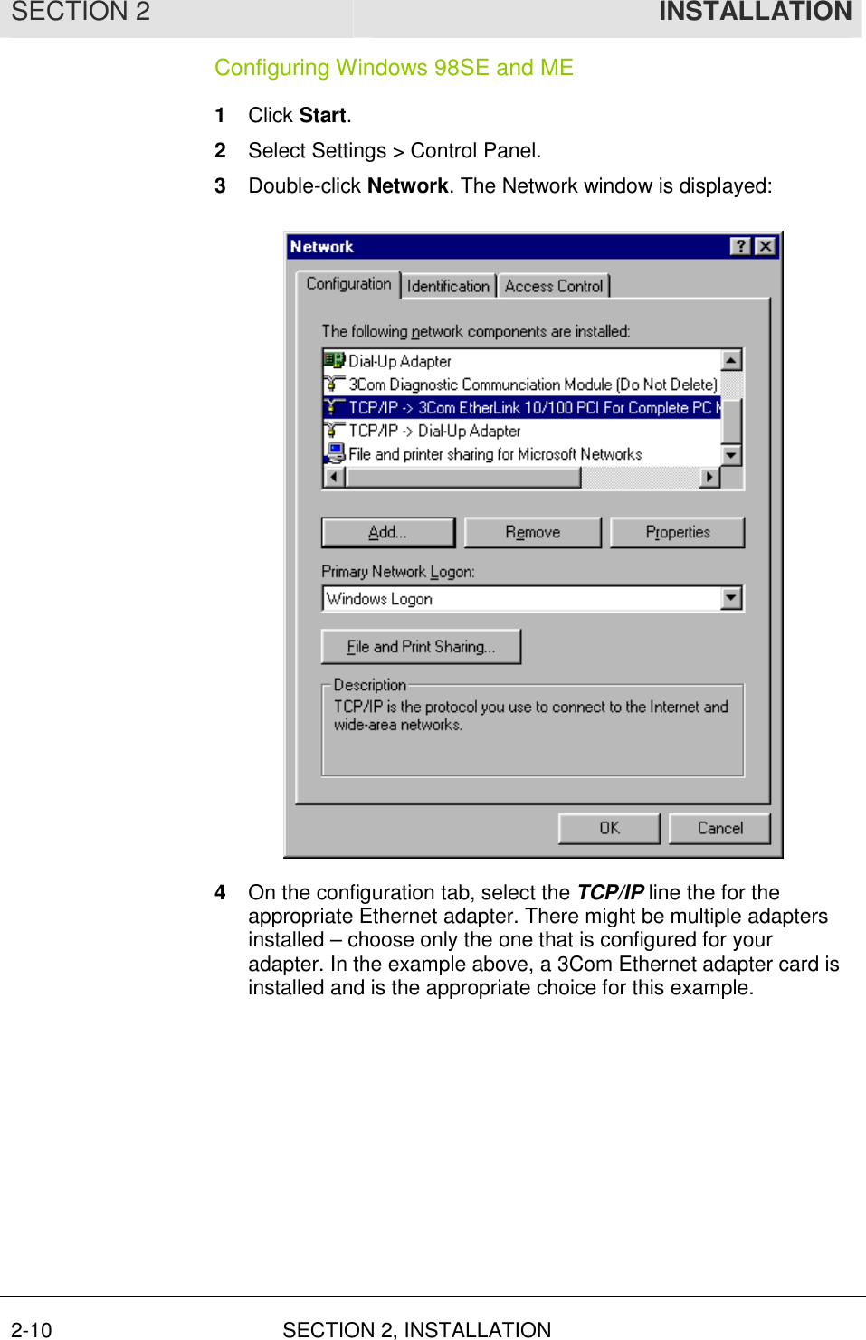
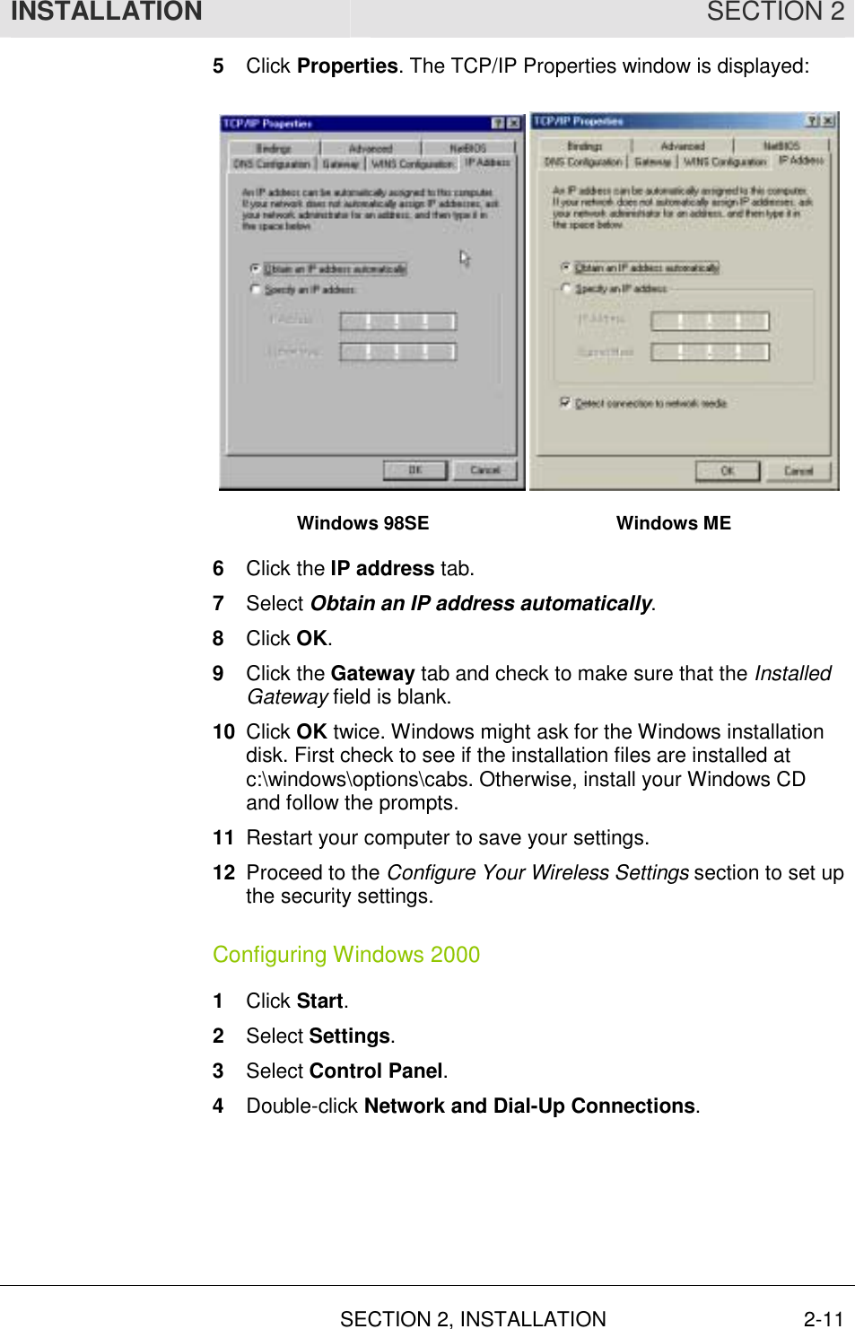
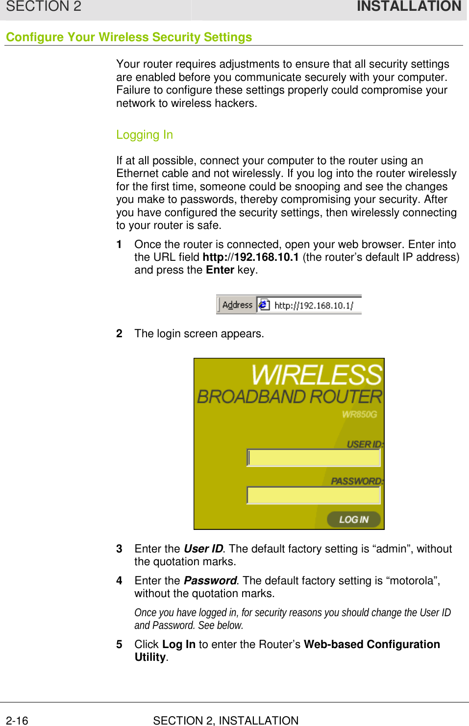
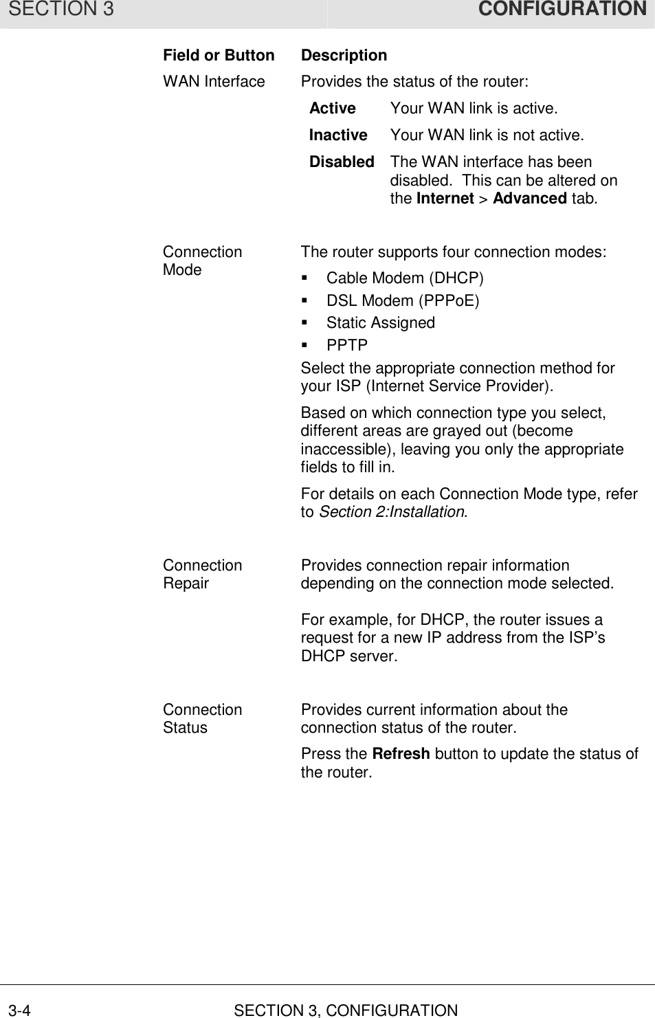
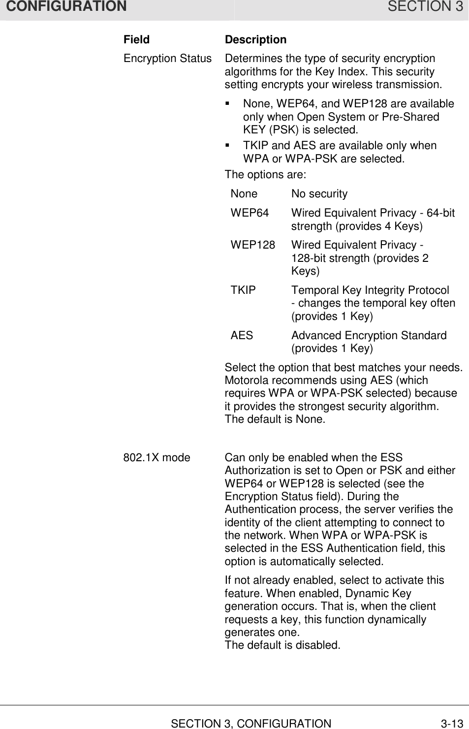
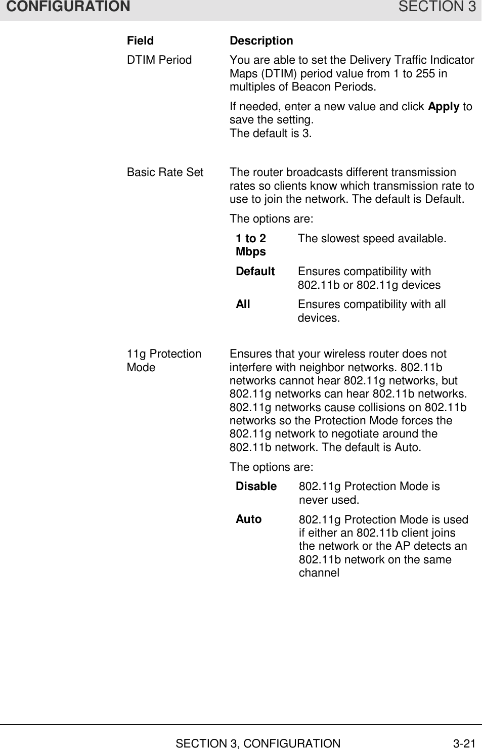
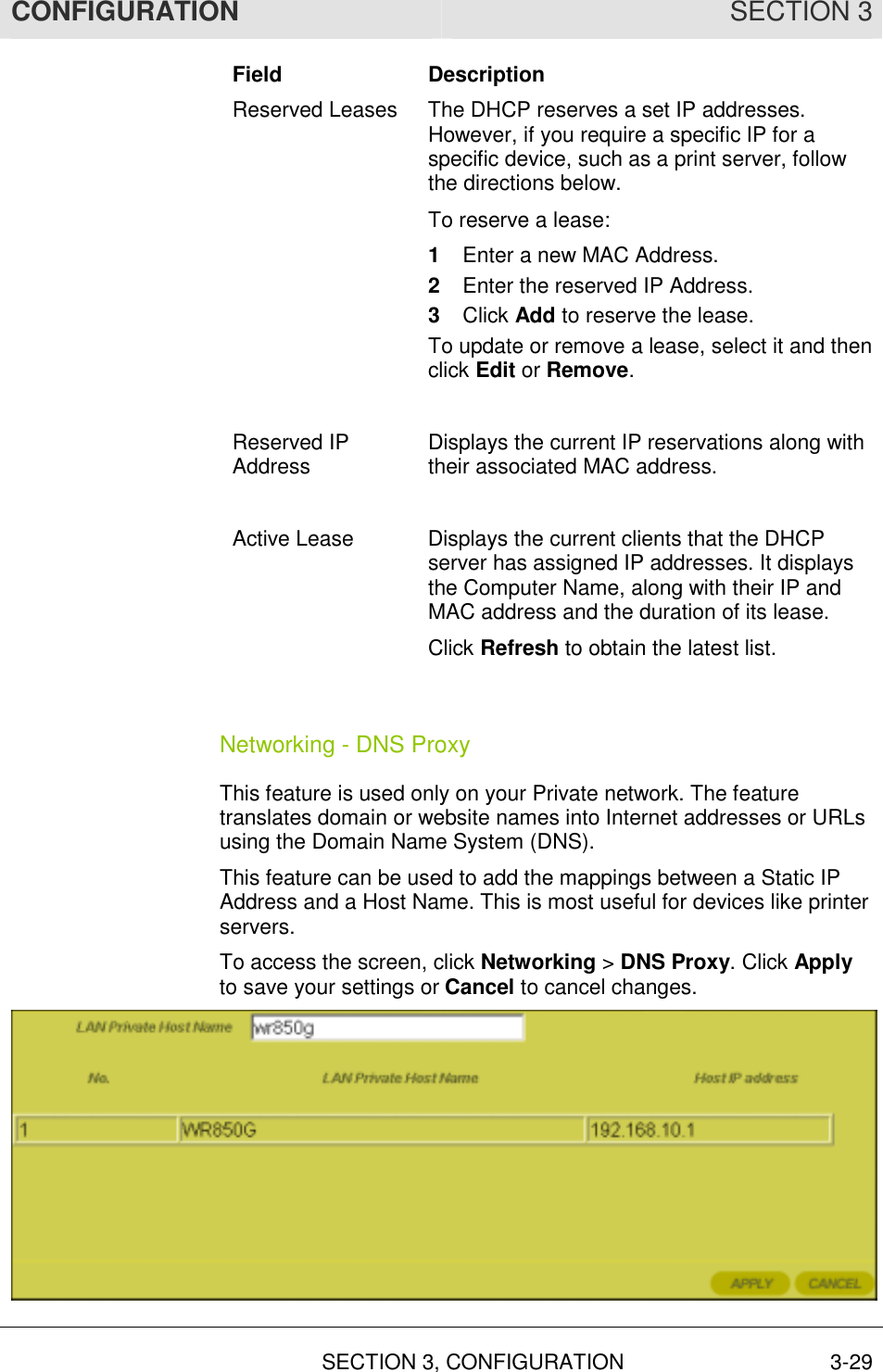
![INSTALLATION SECTION 2 SECTION 2, INSTALLATION 2-3 Wall Mount Installation If you mount the router on the wall, you must: ! Locate the unit as specified by the local or national codes governing residential or business communications services. ! Follow all local standards for installing a network interface unit/network interface device (NIU/NID). If possible, mount the router to concrete, masonry, a wooden stud, or other very solid wall material. Use anchors if necessary; for example if you must mount the unit on drywall. To mount your router on the wall: 1 Print the Wall Mounting Template: 5.1” [129.5mm] The illustration is drawn at a one-to-one scale, which means that when printed, it provides the exact dimensions required to mount the unit.](https://usermanual.wiki/ARRIS/WR850GV2/User-Guide-393231-Page-18.png)