ASA Electronics WVCMSQ1B VOYAGER TOUGHCAM DIGITAL WIRELESS OBSERVATION SYSTEM User Manual Digital Wireless Colour Camera
ASA ELECTRONICS VOYAGER TOUGHCAM DIGITAL WIRELESS OBSERVATION SYSTEM Digital Wireless Colour Camera
UserManual.wiki
>
ASA Electronics
>
WVCMSQ1B User Manual
User Manual
Navigation menu
Upload a User Manual
Namespaces
Wiki Guide
HTML
PDF
Info
Views
User Manual
Discussion / Help
Navigation
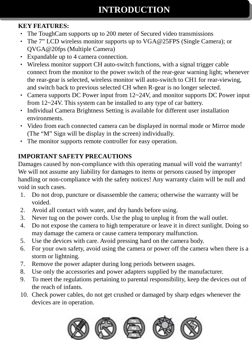
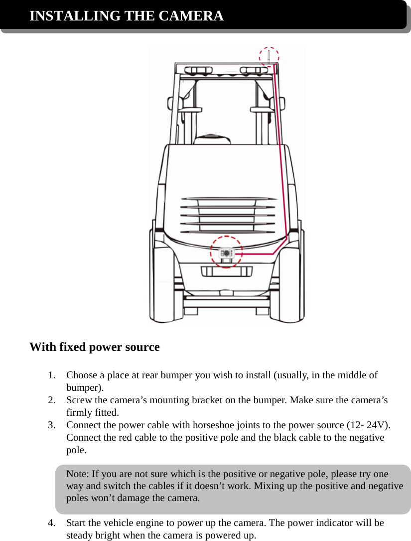
![Note: The camera will be automatically turned on in Channel 1 when the vehicle is in reverse condition. 5. Turn on the monitor. The screen should show the image transmitted from the camera automatically. If it doesn’t, please refer to the Pairing Camera(s) section to pair the camera with the monitor. Using the trigger cable You can use the trigger cable to make the Channel 1 camera display the car rear view automatically when the reverse gear is engaged. 1. Connect the ring-shaped connectors to the fuse of the rear gear to trigger the camera. 2. Connect the other end of the trigger cable to the monitor. 3. Turn on the monitor and shift the gear to Reverse. 4. The screen should show the image of the car rear view automatically. If it doesn’t, please refer to the Pairing Camera(s) section to pair the camera with the monitor. Note: It is strongly recommended to keep the system in QVGA mode with better FPS to ensure smooth images. STOP BACKING when [NO SIGNAL] shows on the monitor. With battery pack (not included in the package) 1. Attach the camera to the battery. Note: If you are not sure which is the positive or negative pole, please try one way and switch the cables if it doesn’t work. Mixing up the positive and negative poles won’t damage the camera. 2. Install the camera and the battery on the vehicle. 3. Press the power button on the battery pack for seconds to power up the camera.](https://usermanual.wiki/ASA-Electronics/WVCMSQ1B/User-Guide-2019551-Page-6.png)
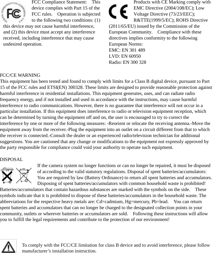
![Monitor Function Buttons Monitor Button Function Remote Controller 1 (Menu Mode) [Cursor Up] / (QUAD View Mode) [Hot key CH1] 2 (Menu Mode) [Cursor Right] / (QUAD View Mode) [Hot key CH2] 3 (Menu Mode) [Cursor DOWN] / (QUAD View Mode) [Hot key CH3] 4 (Menu Mode) [Cursor Left] / (QUAD View Mode) [Hot key CH4] 5 (Menu Mode) [Menu / Enter Button] 6 (SCAN Mode) [SCAN Button] 7 (QUAD Mode) [QUAD Button] Monitor Display Icons Signal Indicator shows signal strength as below: Indicator Signal Level Zero Low Fair Good Perfect Channel Indicator shows your current active camera. Status Indicator appears when the monitor receives no signal. Signal Indicator Channel Indicator Status Indicator 6 7 1 2 3 4 5 5 6 7](https://usermanual.wiki/ASA-Electronics/WVCMSQ1B/User-Guide-2019551-Page-11.png)
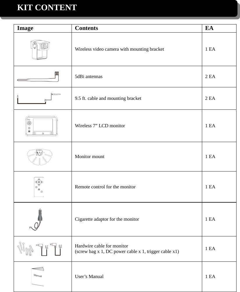
![TROUBLE SHOOTING This section offers some helpful information to overcome most of the problems you may encounter. We hope this section can help you to enjoy a pleasant setup. Problem Possible Causes Remedies System Message shows “NO Signal” on monitor screen No power supply to corresponding camera(s) Check back light, make sure the electricity get through. Check camera wiring again, make sure the polarities is correctly connected. Channel is not paired with camera yet To do the Pairing, shift gear back, have the hand brake ON then go to car rear to press the button. See [Advanced Operation – Pairing Camera] section as a guide. Low signal or unstable signal Antenna directional limitation Adjust camera antenna and receiver position. Strong radio signal near by Keep WIFI router away from the camera and/or receiver. Backing camera image is missing during manual scan Scan channel(s) been set OFF Press [OK] button, go to menu; enable the channel(s). See [Advance Operation – Setting Auto/Manual Scan Sequence] for detail. Dim / over bright image on monitor screen Monitor brightness adjust wrongly. Press [OK] button, go to menu, enter [System Setup]; adjust [Brightness]. See [Advance Operation – System Setup] for detail. Image Frozen and receiver function buttons no respond System crash Use a pin object to press [Reset Switch] to restore the system.](https://usermanual.wiki/ASA-Electronics/WVCMSQ1B/User-Guide-2019551-Page-17.png)