ASA Electronics WVOM74Q VOYAGER TOUGHCAM DIGITAL WIRELESS OBSERVATION SYSTEM User Manual Digital Wireless Colour Camera
ASA ELECTRONICS VOYAGER TOUGHCAM DIGITAL WIRELESS OBSERVATION SYSTEM Digital Wireless Colour Camera
User Manual

TOUGH CAM
Version 1.0
Model: WVOS7MDCL1Q
PLEASE READ CAREFULLY AND SAVE
This manual contains important information about this product’s operation.
If you are installing this product for others, you must have this manual – or a copy –
with the end user.

INTRODUCTION
KEY FEATURES:
• The ToughCam supports up to 200 meter of Secured video transmissions
• The 7” LCD wireless monitor supports up to VGA@25FPS (Single Camera); or
QVGA@20fps (Multiple Camera)
• Expandable up to 4 camera connection.
• Wireless monitor support CH auto-switch functions, with a signal trigger cable
connect from the monitor to the power switch of the rear-gear warning light; whenever
the rear-gear is selected, wireless monitor will auto-switch to CH1 for rear-viewing,
and switch back to previous selected CH when R-gear is no longer selected.
• Camera supports DC Power input from 12~24V, and monitor supports DC Power input
from 12~24V. This system can be installed to any type of car battery.
• Individual Camera Brightness Setting is available for different user installation
environments.
• Video from each connected camera can be displayed in normal mode or Mirror mode
(The “M” Sign will be display in the screen) individually.
• The monitor supports remote controller for easy operation.
IMPORTANT SAFETY PRECAUTIONS
Damages caused by non-compliance with this operating manual will void the warranty!
We will not assume any liability for damages to items or persons caused by improper
handling or non-compliance with the safety notices! Any warranty claim will be null and
void in such cases.
1. Do not drop, puncture or disassemble the camera; otherwise the warranty will be
voided.
2. Avoid all contact with water, and dry hands before using.
3. Never tug on the power cords. Use the plug to unplug it from the wall outlet.
4. Do not expose the camera to high temperature or leave it in direct sunlight. Doing so
may damage the camera or cause camera temporary malfunction.
5. Use the devices with care. Avoid pressing hard on the camera body.
6. For your own safety, avoid using the camera or power off the camera when there is a
storm or lightning.
7. Remove the power adapter during long periods between usages.
8. Use only the accessories and power adapters supplied by the manufacturer.
9. To meet the regulations pertaining to parental responsibility, keep the devices out of
the reach of infants.
10. Check power cables, do not get crushed or damaged by sharp edges whenever the
devices are in operation.
FCC Compliance Statement: This
device complies with Part 15 of the
FCC rules. Operation is subjected
to the following two conditions: (1)
this device may not cause harmful interference,
and (2) this device must accept any interference
received, including interference that may cause
undesired operation.
Products with CE Marking comply with
EMC Directive (2004/108/EC); Low
Voltage Directive (73/23/EEC);
R&TTE(1999/5/EC); ROHS Directive
(2011/65/EU) issued by the Commission of the
European Community. Compliance with these
directives implies conformity to the following
European Norms:
EMC: EN 301 489
LVD: EN 60950
Radio: EN 300 328
FCC/CE WARNING
This equipment has been tested and found to comply with limits for a Class B digital device, pursuant to Part
15 of the FCC rules and ETSI(EN) 300328. These limits are designed to provide reasonable protection against
harmful interference in residential installations. This equipment generates, uses, and can radiate radio
frequency energy, and if not installed and used in accordance with the instructions, may cause harmful
interference to radio communications. However, there is no guarantee that interference will not occur in a
particular installation. If this equipment does interference to radio or television equipment reception, which
can be determined by turning the equipment off and on, the user is encouraged to try to correct the
interference by one or more of the following measures: -Reorient or relocate the receiving antenna.-Move the
equipment away from the receiver.-Plug the equipment into an outlet on a circuit different from that to which
the receiver is connected.-Consult the dealer or an experienced radio/television technician for additional
suggestions. You are cautioned that any change or modifications to the equipment not expressly approved by
the party responsible for compliance could void your authority to operate such equipment.
DISPOSAL If the camera system no longer functions or can no longer be repaired, it must be disposed
of according to the valid statutory regulations. Disposal of spent batteries/accumulators:
You are required by law (Battery Ordinance) to return all spent batteries and accumulators.
Disposing of spent batteries/accumulators with common household waste is prohibited!
Batteries/accumulators that contain hazardous substances are marked with the symbols on the side. These
symbols indicate that it is prohibited to dispose of these batteries/accumulators in the household waste. The
abbreviations for the respective heavy metals are: Cd=cadmium, Hg=mercury, Pb=lead. You can return
spent batteries and accumulators that can no longer be charged to the designated collection points in your
community, outlets or wherever batteries or accumulators are sold. Following these instructions will allow
you to fulfill the legal requirements and contribute to the protection of our environment!
To comply with the FCC/CE limitation for class B device and to avoid interference, please follow
manufacturer’s installation instruction.
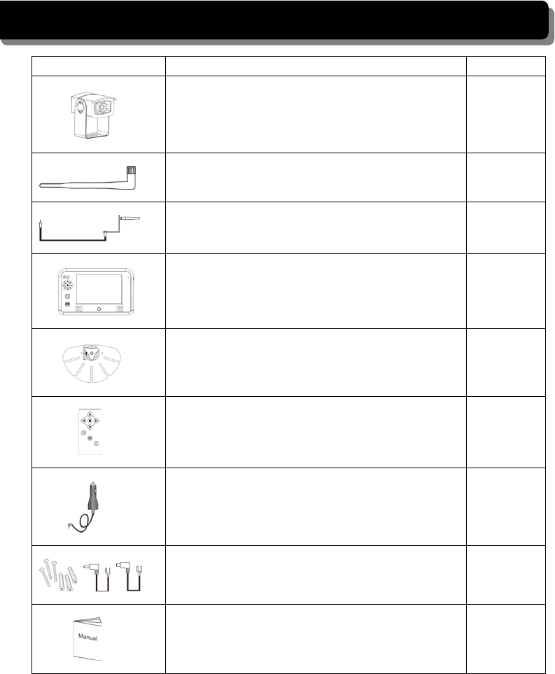
KIT CONTENT
Image
Contents
EA
Wireless video camera with mounting bracket 1 EA
5dBi antennas 2 EA
9.5 ft. cable and mounting bracket 2 EA
Wireless 7” LCD monitor 1 EA
Monitor mount 1 EA
Remote control for the monitor 1 EA
Cigarette adaptor for the monitor 1 EA
Hardwire cable for monitor
(screw bag x 1, DC power cable x 1, trigger cable x1) 1 EA
User’s Manual 1 EA
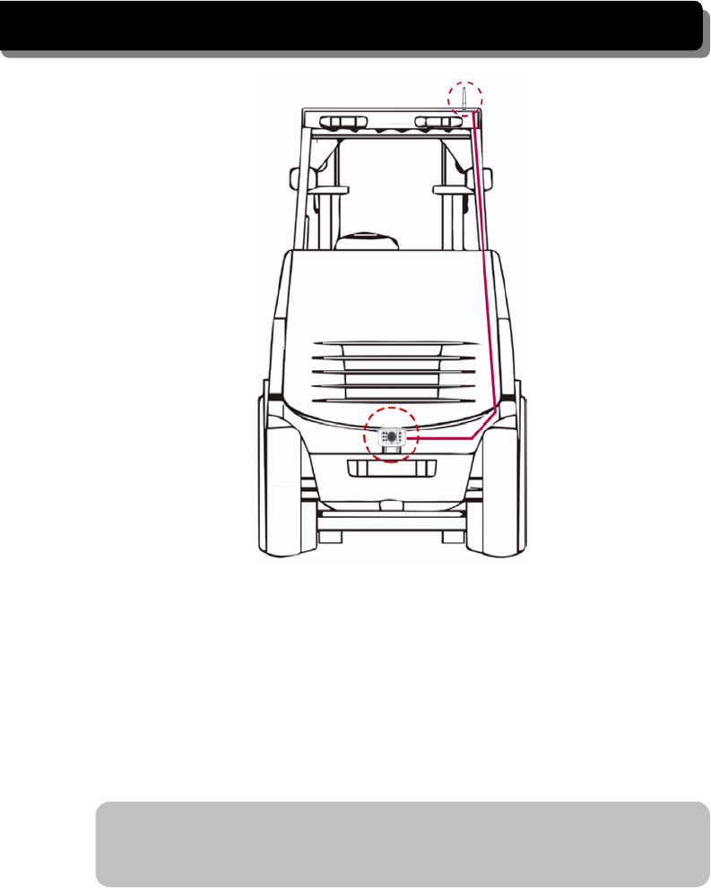
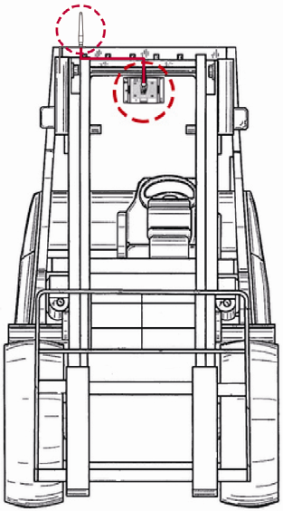
INSTALLING THE CAMERA
With fixed power source
1. Choose a place at rear bumper you wish to install (usually, in the middle of
bumper).
2. Screw the camera’s mounting bracket on the bumper. Make sure the camera’s
firmly fitted.
3. Connect the power cable with horseshoe joints to the power source (12- 24V).
Connect the red cable to the positive pole and the black cable to the negative
pole.
Note: If you are not sure which is the positive or negative pole, please try one
way and switch the cables if it doesn’t work. Mixing up the positive and negative
poles won’t damage the camera.
4. Start the vehicle engine to power up the camera. The power indicator will be
steady bright when the camera is powered up.

Note: The camera will be automatically turned on in Channel 1 when the vehicle
is in reverse condition.
5. Turn on the monitor. The screen should show the image transmitted from the
camera automatically. If it doesn’t, please refer to the Pairing Camera(s) section
to pair the camera with the monitor.
Using the trigger cable
You can use the trigger cable to make the Channel 1 camera display the car rear view
automatically when the reverse gear is engaged.
1. Connect the ring-shaped connectors to the fuse of the rear gear to trigger the
camera.
2. Connect the other end of the trigger cable to the monitor.
3. Turn on the monitor and shift the gear to Reverse.
4. The screen should show the image of the car rear view automatically. If it doesn’t,
please refer to the Pairing Camera(s) section to pair the camera with the monitor.
Note: It is strongly recommended to keep the system in QVGA mode with better
FPS to ensure smooth images. STOP BACKING when [NO SIGNAL] shows on
the monitor.
With battery pack (not included in the package)
1. Attach the camera to the battery.
Note: If you are not sure which is the positive or negative pole, please try one
way and switch the cables if it doesn’t work. Mixing up the positive and negative
poles won’t damage the camera.
2. Install the camera and the battery on the vehicle.
3. Press the power button on the battery pack for seconds to power up the camera.
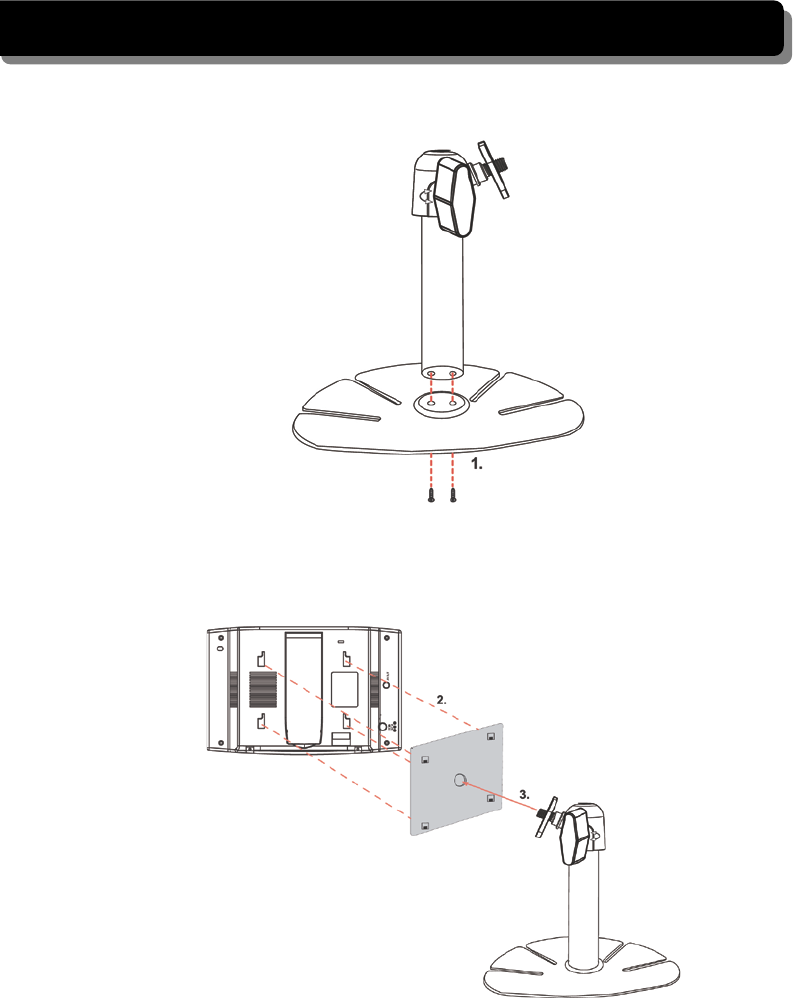
INSTALLING THE MONITOR
1. Screw the antenna on the antenna connector.
2. Secure stand base to stand with provided screws.
3. Fix the mounting metal panel to the back panel of monitor.
4. Secure stand to mounting metal panel, adjust proper view angle, and secure the joint
with T-bolt.
5. Choose a place in car you wish to stick, and fix the monitor with provided twin
adhesive in the package.
6. Connect the cigarette adaptor to the DC power jack of the LCD monitor.
7. Plug the power unit to the cigarette power source beside the driver’s seat and turn on
the ignition and press the Power button to turn on the monitor.
8. Stand the receiver antenna upright to have the best reception.
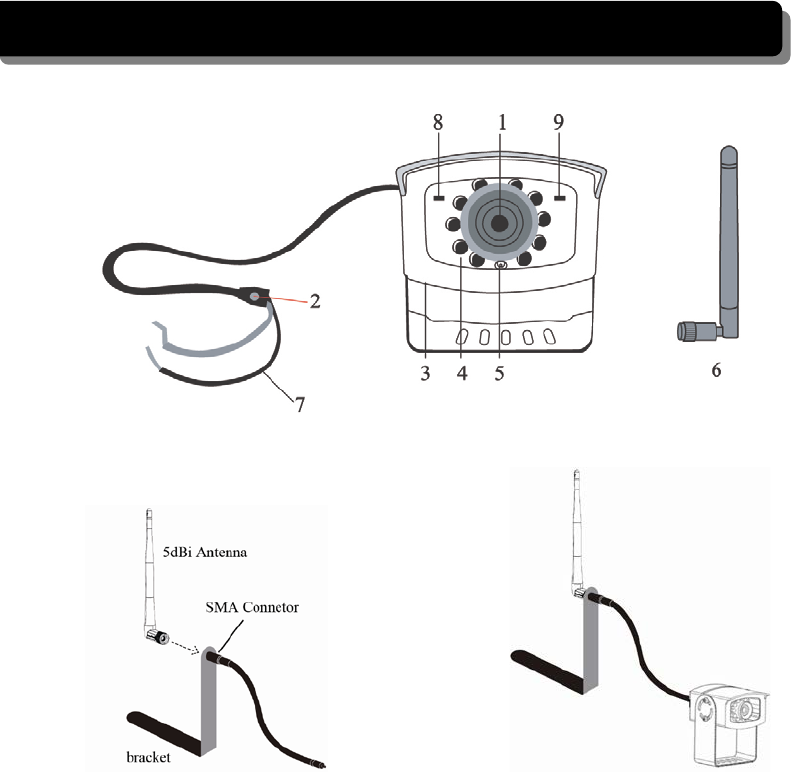
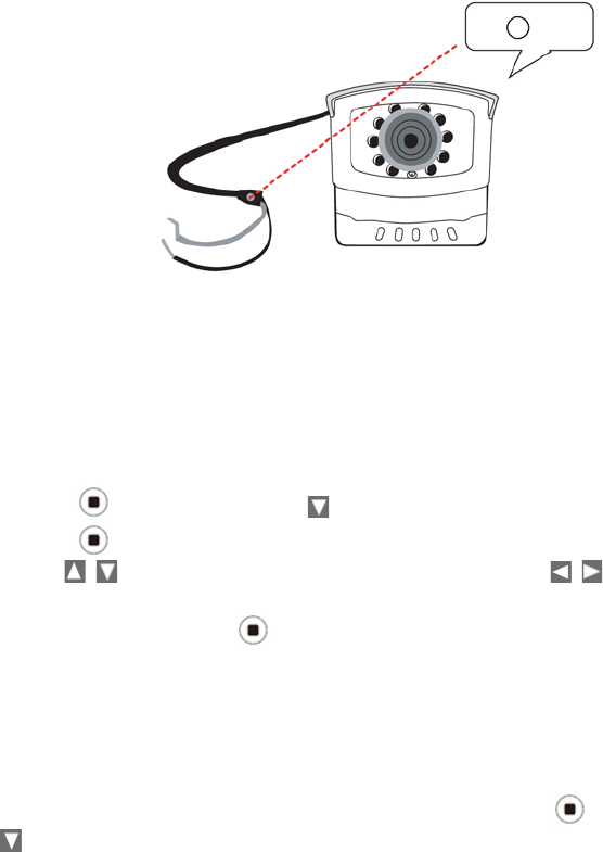
GETTING TO KNOW YOUR CAMERA
1. Camera Lens
2. Pairing Key
3. Mounting Bracket
4. IR LEDs
5. EDS
6. Antenna
7. Power cord to the vehicle back light
8. Link LED Indicator
9. Power LED Indicator
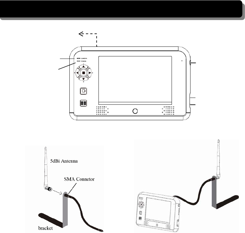
GETTING TO KNOW YOUR RECEIVER
Power Button
Link Indicator
Power Indicator
Antenna Socket
Trigger Cable
Power Adaptor
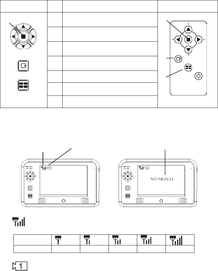
Monitor Function Buttons
Monitor Button Function Remote Controller
1
(Menu Mode) [Cursor Up] /
(QUAD View Mode) [Hot key CH1]
2
(Menu Mode) [Cursor Right] /
(QUAD View Mode) [Hot key CH2]
3
(Menu Mode) [Cursor DOWN] /
(QUAD View Mode) [Hot key CH3]
4
(Menu Mode) [Cursor Left] /
(QUAD View Mode) [Hot key CH4]
5 (Menu Mode) [Menu / Enter Button]
6 (SCAN Mode) [SCAN Button]
7 (QUAD Mode) [QUAD Button]
Monitor Display Icons
Signal Indicator shows signal strength as below:
Indicator
Signal Level
Zero
Low
Fair
Good
Perfect
Channel Indicator shows your current active camera.
Status Indicator appears when the monitor receives no signal.
Signal Indicator
Channel Indicator
Status Indicator
6
7
1
2
3
4
5
5
6
7
CONFIGURING YOUR RECEIVER
Press the Power button to power ON the monitor. Press and hold to power OFF the
monitor.
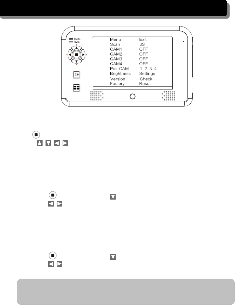
Press (MENU button) to enter/exit the Main menu.
Use the (Left / Right / Up / Down) buttons to navigate through menu items
and change the settings.
Scan frequency
Setup the time interval for the camera channels to switch in Scan mode (3, 8 or 12
seconds)
1. Press (MENU button) and to choose the SCAN function
2. Press to choose the scan frequency. You can configure the system to
perform scanning every 3 seconds / 8 seconds / 15 seconds.
Camera setting (CAM 1 – 4)
Turn ON/OFF the specified camera or set to Mirror to mirror the camera image. If the
camera is set OFF, the camera image won’t show on the monitor even it is supplied with
power.
1. Press (MENU button) and to choose CAM 1.
2. Press to turn ON/OFF CAMERA 1 or MIRROR the camera image.
3. Repeat step 1 to 2 for camera 2 ~ 4.
Note: when you install the camera(s) toward the opposite direction to which you’re
viewing, such as the rear camera, please configure the camera to MIRROR to
acquire the normal screen image.
Pairing camera(s)
When you install an extra camera or if the monitor doesn’t detect it, please use this feature
to pair the camera with the monitor.
IMPORTANT:
Before pairing the camera, make sure camera power cord is well connected to a
constant 12-24V DC power source. Please refer to the With battery pack section and
follow the instruction in the Installing the Camera chapter to install the camera
properly.
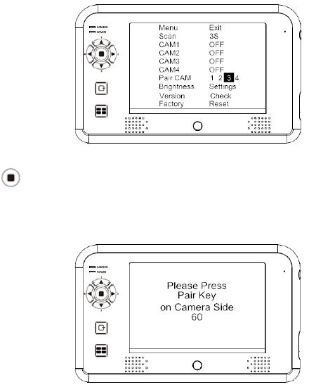
Example: If you want to pair a new camera to channel 3, please follow the steps below:
1. Press (MENU button) to choose the channel 3 in the Pair CAM function and
start the pairing process.
2. System will count down within 60 seconds, system message as shown:
3. Within 60-second count down, press the Link Key on the camera cable
4. Once pairing completed, the monitor will display the camera image immediately.
Brightness
Set up the brightness of the cameras for different environment. Each camera can be
configured individually.
1. Press (MENU button) and to choose the Brightness function
2. Press (MENU button) to enter the sub menu
3. Use to choose the monitor or camera 1~4, and press to adjust the
brightness.
4. Choose EXIT and press (MENU button) to return to the main menu.
Monitor and Camera Version
Use this feature to check the monitor and camera version number when it is necessary.
If you need to check the monitor and camera version number, press (MENU button)
and to check the monitor and camera version.

Factory Reset
Restore the monitor to the factory default settings.
1. Press (MENU button) and to choose the Factory option.
2. Press (MENU button) to restore the default settings as below.
CAM4 08
Setting SCAN Mode
Press the SCAN button to enter the SCAN mode and switch between camera channels
automatically.
1. Press (MENU button) and use (Left / Right) to turn all available channels
ON.
2. Press (SCAN button) to enter SCAN Mode.
3. The camera images will be displayed periodly in scan mode. Unavailable channel will
be displayed as blank screen.
To leave SCAN display, please press (Left / Right / Up / Down) to go
to the specified channel.
Setting QUAD Display
Press the QUAD button to enter the QUAD mode and display all the camera images on
the monitor.
1. Press (MENU button) and use (Left / Right) to turn all available channels
ON.
2. Press (QUAD button) to enter QUAD Mode.
3. All camera images will be display on the monitor at the same time. Unavailable
Scan 3S
CAM1 ON
CAM2 ON
CAM3 ON
CAM4 ON
Pair CAM 1 2 3 4
Brightness Monitor 08
CAM1 08
CAM2 08
CAM3 08
CAM4 08

channel will be displayed as blank screen.
To leave QUAD display, please press (Left / Right / Up / Down) to go
to the specified channel.
IMPORTANT:
1. This function is available for multi cameras user. Before setting QUAD display,
make sure all cameras are paired to assigned channels. Please refer to the Pair CAM
section for instruction.
QUAD display will be restored to one camera display every time after your press
directional keys for manual scan.
2. To display properly, TURN ON all available channels PRIOR to entering into QUAD
mode.
Note: In QUAD display, the Camera Pairing function is not available.

TROUBLE SHOOTING
This section offers some helpful information to overcome most of the problems you may
encounter. We hope this section can help you to enjoy a pleasant setup.
Problem
Possible Causes
Remedies
System Message shows
“NO Signal” on monitor
screen
No power supply to
corresponding camera(s)
Check back light, make
sure the electricity get
through. Check camera
wiring again, make sure the
polarities is correctly
connected.
Channel is not paired with
camera yet
To do the Pairing, shift
gear back, have the hand
brake ON then go to car
rear to press the button.
See [Advanced Operation –
Pairing Camera] section as
a guide.
Low signal or unstable
signal
Antenna directional
limitation
Adjust camera antenna and
receiver position.
Strong radio signal near by
Keep WIFI router away
from the camera and/or
receiver.
Backing camera image is
missing during manual
scan
Scan channel(s) been set
OFF
Press [OK] button, go to
menu; enable the
channel(s). See [Advance
Operation – Setting
Auto/Manual Scan
Sequence] for detail.
Dim / over bright image
on monitor screen
Monitor brightness adjust
wrongly.
Press [OK] button, go to
menu, enter [System
Setup]; adjust [Brightness].
See [Advance Operation –
System Setup] for detail.
Image Frozen and
receiver function buttons
no respond
System crash
Use a pin object to press
[Reset Switch] to restore
the system.

PRODUCT SPECIFICATION
Camera
Image Sensor
Type:
CMOS1/4
Resolution:
640*480
Optical
Lens Type:
Glass
Lens Focal Length:
2.5MM
View Angle:
Horizontal:87°±2°; Vertical:62°±2°
Resolution (TV Line):
480*272
Night Vision
Total IR LED:
10 PCS
LED Angle:
120
LED Wave Length:
850nm
EDS Activate LUX:
1-8LUX
Identified Range:
5-8m
Transceiver
Frequency:
2.402-2.480GHZ
Modulation:
GFSK
Transmission Power:
<20 dBm(extension cable+antenna)
Communication distance:
200M
Power Source
Power Supply:
DC 12-24V
Current Consumption:
IR ON:220mA; IR OFF:150mA
Waterproof
IPxx
IP66
Monitor
LCD Panel
Size
:
7.0
〞
Resolution
:
480*234
Luminance:
200cd/
㎡
Back Light
:
LED
Transceiver
Frequency:
2.405-2.480GHZ
Modulation :
GFSK
Sensitivity
:
-82DBm
TV Format
NTSC/PAL
Video
Compression
:
MJPEG
Resolution
:
640*480
Video Output Level
:
1Vp-p/75ohm
Frame Rate
:
12-25 FPS
LCD View Angle
Up /Down:
130°
Left/Right:
140°
Interface
DC IN
12-24V


FCC NOTE:
This device complies with Part 15 of the FCC Rules.
Operation is subject to the following two conditions: (1) this device may not cause
harmful interference, and (2) this device must accept any interference received,
including interference that may cause undesired operation.
THE MANUFACTURER IS NOT RESPONSIBLE FOR ANY RADIO OR TV
INTERFERENCE CAUSED BY UNAUTHORIZED MODIFICATIONS OR CHANGE
TO THIS EQUIPMENT. SUCH MODIFICATIONS OR CHANGE COULD VOID AND
CHANGE ANNTENA WHICH THE MANUFACTURER PROVIDES.
IT IS THE USER'S AUTHORITY TO OPERATE THE EQUIPMENT.
This equipment has been tested and found to comply with the limits for a Class B
digital device, pursuant to part 15 of the FCC Rules. These limits are designed to
provide reasonable protection against harmful interference in a resi dential installation.
This equipment generates, uses and can radiate radio frequenc y energy and, if not
installed and used in accordance with the in structions, may cause harmful interference
to radio communications. However, there is no guarantee that interference will not
occur in a particular insta llation. If this equipment does cause harmful interference to
radio or television reception, which can be determined by turning the equipment off
and on, the user is encouraged to try to corr ect the interference by one or more of the
following measures:
-- Reorient or relocate the receiving antenna.
-- Increase the separation between the equipment and receiver.
-- Connect the equipment into an outlet on a circuit different from that to which the
receiver is connected.
-- Consult the dealer or an experien ced radio/TV technician for help.
To maintain compliance with FCC’s RF exposure guidelines, this equipment should be
installed and operated with a minimum distance of 20cm between the radiator and your
body.