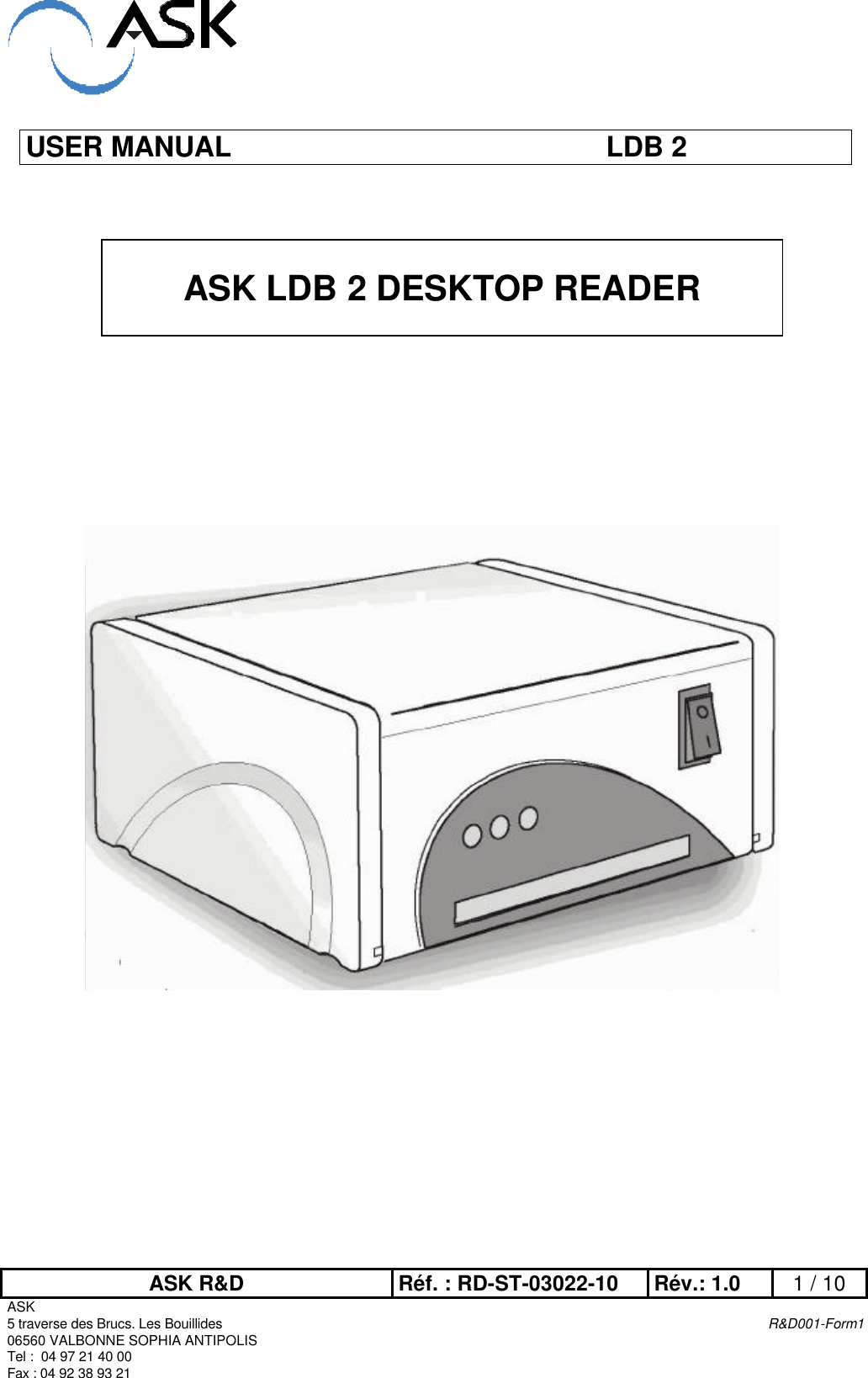
ASK LDB2-RDDE03082 Tag Reader User Manual RD MU 03036 10

ASK Tag Reader RD MU 03036 10

Users Manual

ASK R&D Réf. : RD-ST-03022-10 Rév.: 1.0 1 / 10ASK5 traverse des Brucs. Les Bouillides R&D001-Form106560 VALBONNE SOPHIA ANTIPOLISTel :  04 97 21 40 00Fax : 04 92 38 93 21USER MANUAL LDB 2ASK LDB 2 DESKTOP READER
ASK R&D Réf. : RD-ST-03022-10 Rév.: 1.0 2 / 10ASK5 traverse des Brucs. Les Bouillides R&D001-Form106560 VALBONNE SOPHIA ANTIPOLISTel :  04 97 21 40 00Fax : 04 92 38 93 21FCC Compliance StatementsThis equipment has been tested and found to comply with the radiated limits for a Class Bdigital device, pursuant to Part 15 of the FCC Rules. These limits are designed to provide areasonable protection against harmful interferences in a residential installation. Thisequipment generates, uses and can radiate radio frequency energy and, if not installed andused in accordance with the instructions, may cause harmful interference to radiocommunications. However, there is no guarantee that interference will not occur in a particularinstallation. If this equipment does cause harmful interference to radio or television reception,which can be determined by turning the equipment off and on, the user is encouraged to trythe correct interference by one or more of the following measures:- Reorient or relocate the receiving antenna.- Increase the separation between the equipment and receiver.- Connect the equipment into an outlet on a circuit different from that to which thereceiver is connected.- Consult the dealer or an experienced radio/TV technician for help.This device complies with Part 15 of the FCC rules. Operation is subject to the following twoconditions. (1) This device may not cause harmful interferences. And (2) this device mustaccept any interference received, including interference that may cause undesired operation.The ASK LDB 2 reader was submitted and a grand of authorization received from the FCC asdevice under the intentional radiator requirements of Part 15, Subpart C.The party that incorporates this device into their product is responsible for verification of theemissions produced by the final product and must adhere to the limits specified in the Code ofFederal Regulation 47, Part 15, subpart B.Compliance accessories: The accessories associated with this equipment are: shieldedserial cable with ferrite tube and linear sector adaptor (12V DC 500mA). These accessoriesare required to be used in order to ensure compliance with the FFC rules.Caution: Any changes or modification not approved by ASK could void user’s authority tooperate the equipment. Switching power mode adaptors are prohibited.CE Compliance statementThe ASK LDB 2 reader is in conformity with European requirements, this product has beenassessed to the following standard:EN 300 330EN 301 489-3EN 50121-4EN 60950-1
ASK R&D Réf. : RD-ST-03022-10 Rév.: 1.0 3 / 10ASK5 traverse des Brucs. Les Bouillides R&D001-Form106560 VALBONNE SOPHIA ANTIPOLISTel :  04 97 21 40 00Fax : 04 92 38 93 21TABLE OF CONTENTS1SCOPE OF MANUAL 41.1 UNPACKING AND INSPECTION 42LDB 2 READER 42.1 READER COMPONENTS 52.1.1 Coupler board 52.1.2 Antenna board 62.1.3 Power supply board 62.1.4 Contact card interface board 72.2 Assembly 73READER SETUP 83.1 INSTALLING A NEW SAM IN READER 83.2 READER CONNEXION 94HOW TO USE THE READER 104.1 CONTACTLESS OPERATIONS 104.2 CONTACT OPERATIONS 104.3 SOFTWARE 104.4 CLEANING 10
USER MANUEL LDB 2DESKTOP READERASK R&D Réf. : RD-MU-03036-10 Rév.: 1.0 4 / 10Copyright ASK SA - 20031 SCOPE OF MANUALThis manual describes ASK LDB 2 reader main features and setup information. This manualis intended for use by end users. No specific tools are required for operation described in thisdocument.1.1 UNPACKING AND INSPECTIONEach LDB 2 kit is shipped with :- serial cable (length : 3 meters)- This user manual- One power supply 110V AC / 12V DC 500mA- LDB 2 reader packaged in plastic case2 LDB 2 READERLDB 2 readers are contactless readers designed for integrators and operators asdevelopment tools as well as desktop readers for card issuing center and point of sales.LDB 2 provides the communication between a terminal and customer smart cards.
USER MANUEL LDB 2DESKTOP READERASK R&D Réf. : RD-MU-03036-10 Rév.: 1.0 5 / 10Copyright ASK SA - 20032.1 READER COMPONENTSLDB 2 consists of a control board called ”coupler board”, and antenna board, a DC supplyconverter board (with two extra SAM sockets) and a contact card interface board.2.1.1 COUPLER BOARDThe coupler board contains a microprocessor, non-volatile memory and a radio frequencytransmitting circuitry. This board communicates with smart cards via RF link (provided by anantenna board), and to the terminal via RS-232 interface. The serial rate is set to 115,2 bps.The coupler platforms are GEN320 or GEN325 elements which can be purchased separatelyat ASK. These two OEM coupler boards are compliant with ISO/IEC14443-2 directives (Radiofrequency power and signal interface). Communications can be executed according to thetype A or type B of the directive.Figure 1 : GEN 320-GEN 325 boardGEN 320 and GEN 325 board are strictly identical, except that on GEN 325, PHILIPS ‘sRC500 chip is added. In this case, the chip just manages MIFARE cryptography mode.The RC500 chip is located (or not) at the bottom of the printed circuit board (PCB).SAM locationRS232 connectorAntenna connectorRC500 chipTOP VIEWBOTTOM VIEWFigure 3 : GEN 320 boardFigure 2 : GEN 325 board
USER MANUEL LDB 2DESKTOP READERASK R&D Réf. : RD-MU-03036-10 Rév.: 1.0 6 / 10Copyright ASK SA - 20032.1.2 ANTENNA BOARDThe antenna board consists of a printed circuit board with copper traces forming the transmitand the receive antenna. Antenna may be one of several types, varying in dimensions andconnection. LDB 2 receives GEN 530 antenna because its area (110x120mm) matches wellwith a desktop application. This antenna has a tuning capacitor, but no setting is requiredbecause it has been optimized in factory.Figure 4 : LDB 2 antenna board : GEN 5302.1.3 POWER SUPPLY BOARDThis board contains a DC-DC converter and two extra SAM locations. Input line should befrom 9V to 36V DC. Typically an AC power bloc with output 12V 500mA (without regulation)should be used.Figure 5 : LDB 2 DC conversion / SAM extension board : GEN 351SAM location
USER MANUEL LDB 2DESKTOP READERASK R&D Réf. : RD-MU-03036-10 Rév.: 1.0 7 / 10Copyright ASK SA - 20032.1.4 CONTACT CARD INTERFACE BOARDThis card has been added for allowing standard contact card transactions.Figure 6 : LDB 2 contact card interface board : GEN 3622.2 ASSEMBLYInside the plastic case these boards are stacked together (Figure 7). This way, no cables areneeded :Figure 7 : stacked boards in readerContact card connectorContact card interface boardPower supply boardcoupler boardAntenna board
USER MANUEL LDB 2DESKTOP READERASK R&D Réf. : RD-MU-03036-10 Rév.: 1.0 8 / 10Copyright ASK SA - 20033 READER SETUP3.1 INSTALLING A NEW SAM IN READERIn most applications, one SAM (Security Application Module) or more is required.These components are provided separately, so to set a SAM, the plastic caseshould be opened.For opening, flip over the plastic case. You have to put a blade in the rear slot andlift the bottom of the case in order to set free a central ergot. Then the bottom of thebox should be removed by sliding in the front side direction.The stacked board will appear as in Figure 7, the first SAM should be installed oncoupler board GEN 32X (Figure 1) and next SAMs should be installed on DCconversion board GEN 351 (Figure 5).Caution : In a first time, µSIM SAMs must be gently inserted in the open doorsocket (Figure 8), then in a second time the door should be locked.Figure 8 : SAM in open doorSAM
USER MANUEL LDB 2DESKTOP READERASK R&D Réf. : RD-MU-03036-10 Rév.: 1.0 9 / 10Copyright ASK SA - 20033.2 READER CONNEXIONThe reader’s DB9 should be connected to a RS232 serial port, usually to acomputer via the serial cable provided.Plug the main adapter included in the « Power-Jack » connector. The main adaptershould provide 12V DC – 500mA.Turn on the switch located at the front side, the red LED will light at power-on. TheLDB 2 is then in power and ready to work.Figure 9 : LDB 2 connexionsSerial connectorTo computerPower jack
USER MANUEL LDB 2DESKTOP READERASK R&D Réf. : RD-MU-03036-10 Rév.: 1.0 10 / 10Copyright ASK SA - 20034 HOW TO USE THE READER4.1 CONTACTLESS OPERATIONSAll the top surface of LDB 2 reader is active. Contactless smart card must be laid flat on thereader, yellow LED is turned on when operation is correct.4.2  CONTACT OPERATIONSThe smart card should be inserted, chip on top, in the front slot of the LDB 2 reader (cardcontact faces triangle on reader front side).The card should be pushed until a resistance appears (reader’s contacts fall down on card’scontact).4.3  SOFTWAREThe LDB is delivered by default with an application software called CSC which supports theASK cards and C.ticket families.The external LEDs of the reader can be controlled by customer applicative software usingCSC software commands.In the same way, the GEN360 contact card reader and the extra SAM modules supported bythe GEN351 board have to be managed by the host application via CSC protocol.4.4  CLEANINGNo adjustments on the reader are required. To clean, simply wipe with a wet cloth and plasticcleaner, abrasive products are prohibited.

Navigation menu