ASOKA USA PL7070-COM PLC/RS-485 Adapter User Manual T37PL7070 COM Uer Manual
ASOKA USA Corporation PLC/RS-485 Adapter T37PL7070 COM Uer Manual
T37PL7070-COM_Uer Manual

PLC/RS-485 Adapter
User’s Guide
PL7070-COM
QUICKFIND L
OCATOR
Contact
Information
Getting Help
Table of Contents
Installation
66-0386-01Rev.001

2 of 20
© 2013 Asoka USA Corporation
ALL RIGHTS RESERVED
Notice: No part of this publication may be reproduced or transmitted in any form or by any means, electronic or
mechanical, including photocopying and recording, or stored in a database or retrieval system for any
purpose without the express written permission of Asoka USA Corporation.
Asoka USA Corporation reserves the right to make changes to this user’s guide at any time without notice and
assumes no responsibility for its use. Asoka USA products and services can only be ordered under the terms and
conditions of Asoka USA Corporation's applicable agreements. All of the features described in this user’s guide
may not be currently available. Refer to the most recent product announcement for information about feature
and product availability.
This user’s guide contains the most current information available at the time of publication. When new and/ or
revised information becomes available, this entire user’s guide is updated and distributed to all registered users.
All company and product names mentioned herein are trademarks of their respective companies. Mention of
third-party products is for informational purposes only and constitutes neither an endorsement nor a
recommendation. Asoka USA Corporation assumes no responsibility with regard to the performance or use of
these products.
Revision
Date
Description
66-0386-01Rev.001 Aug.
2013
Preliminary Release
Changes in This Revision
• Not applicable (preliminary release)

3 of 20
Contact Information
For more information about the PLC/RS-485 Adapter or any of Asoka’s other leading-
edge solutions, please contact us using any of the following methods:
z Voice calls: We welcome your calls Monday through Friday, from 9:00 am
to 5:00 pm Pacific Time at (408) 550-8167. Voice mail is available during non-
business hours.
z Email: If you prefer, you can send information requests to our e-mail address:
sales@asokatech.com.
z Fax calls: You can also send your requests for information to our 24-hour fax
number: (408) 884-2390.
z Web site: Our Web site contains valuable information about our products,
solutions, and services. We encourage you to visit us at
http://www.asokatech.com.
Getting Help
Asoka USA backs its products with unparalleled customer service and technical support
for our valued customers.
Customer Service
Customer service, the customer-satisfaction arm of Asoka USA, is available Monday
through Friday, from 9:00 am to 5:00 pm Pacific Time, by calling (408) 550-8167 or
emailing custserv@asokatech.com
Technical Support
Technical support is available Monday through Friday, from 9:00 am to 5:00 pm
Pacific Time, by calling (408) 550-8173 or through email at support@asokatech.com.
Please provide the following information about the problem:
z Product name, model number, part number (if applicable) and serial number
z System configuration, including a description of the devices connected to your
PL7070-COM
z The circumstances surrounding the error or failure
z A detailed description of the problem and what has been done to try to solve it

4 of 20
Table of Contents
1
Installation Setup .......................................................................... 5
Package Contents ................................................................................................... 5
Finding a Suitable Location ..................................................................................... 5
Simple Connection (Peer to Peer) ............................................................................ 6
Troubleshooting ............................................................................. 7
Specifications ................................................................................. 8
RS-485 DB9 Male pinout assignment ....................................................................... 9
Components ................................................................................. 10
Warranty 14
FCC Notice ..................................................................................... 16
5 of 20
Installation Setup
Congratulations on your purchase of the PL7070-COM PLC/RS-485 Adapter.
The PL7070-COM adapter allows you to transmit RS-485 data between two points via the
existing electrical wiring by simply plugging the PL7070-COM directly into an electrical
outlet. The PL7070-COM acts as a bridge for the RS-485 signal. This manual describes
how to install your PL7070-COM PLC/RS-485 Adapter.
Package Contents
z Two (2) PLC/RS-485 Adapters(PL7070-COM)
z Quick Installation Guide
z Warranty and Support Information Card
If any of the parts are incorrect, missing, or damaged, contact the retailer where
you made your purchase. Keep the carton, including the original packing materials, in
case you need to return the unit for repair.
Finding a Suitable Location
Find a suitable location to install your PL7070-COM adapters. If possible, find a location
that has:
• Acceptable temperature and humidity ranges (see the PL7070-COM specifications
on page 9)
• Free of strong electromagnetic field generators (such as motors), vibration dust
and direct exposure to sunlight.
• An electrical outlet for your PL7070-COM adapter that is within the RS-485
distance specs.
6 of 20
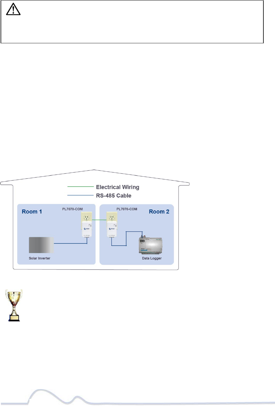
Simple Connection (Peer to Peer)
1. Connect one PL7070-COM device to your Solar Inverter with an RS-485 cable
(twisted wire); then plug it into a wall outlet. For the PL7070-COM Pin Out
Wiring Specifications, see page 11.
2. Connect the other PL7070-COM device to your Data logger with an RS-485
cable(twisted wire); then plug it into a wall outlet.
3. Set the Baud Rate on both adapters to the same Baud Rate (speed) as the Solar
Inverter and the Data Logger. You can change the Baud Rate by pressing on the
Baud Rate Key (see page 10 for the location of the Baud Rate Key button). For
additional information on how to use the Baud Rate Key button, see page 13.
4. See Figure-1 below for your reference.
Figure-1 Solar Inverter and Data Logger connection via PL7070-COM PLC adapters.
Congratulations! You have completed the installation of the
PL7070-COM.
NOTE: Do not plug the PL7070-COM adapter into a power strip, UPS
(Uninterruptable Power Supply) or surge protector device. This may prevent the
unit from working properly or degrade the PLC (Powerline communication)
network performance.

7 of 38
Troubleshooting
Following are solutions to a few situations you might encounter. If you do not find a
solution in this chapter, contact Asoka USA Technical Support by phone at (408) 550-
8173 or through email at support@asokatech.com.
Symptom:
I can't connect to anything and there are no lights (LED) activity on my PL7070-COM.
Solution:
• Unplug the device from the electrical outlet in question.
• Locate another available outlet.
• Test the outlet by plugging in an electrical device such as a lamp or radio.
• Plug the PL7070-COM into the working electrical outlet.
• Check to see if the lights (LED) work
• If the above does not work, the device might be defective.
• At this point, please contact Asoka Technical Support for instructions on
returning the device for repair or replacement.
Symptom:
The lights seem to be functioning, however, the solar inverter and data logger do not
communicate (no connection).
Solution:
• Check the Baud rate on both PL7070-COM (front Baud rate LED indicator), the
Baud rate must be the same on both PL7070-COM devices. If the Baud is not the
same, simply press the Baud rate button to change it to the correct speed.
8 of 38
Specifications
This appendix lists the specifications for your PL7070-COM adapter.
Standards Compliance: •HomePlug® AV • IEEE 802.3, IEEE 802.3x, IEEE 802.3u,IEEE1901
Network Interface: RS-485
PHY-Rate: Up to 200 Mbps
Distance: Over 300 meters
Operating Frequency: 2 to 30 MHz
Modulation Schemes: • Orthogonal Frequency Division Multiplexing (OFDM) • QAM
1024/256/64/16 •QPSK •BPSK
EMI and Safety: • FCC Part 15 Class B •UL (US and Canada) •CE
Additional Protocols: Two-wire RS-485, A bridge between RS-485 and PLC
Power Supply: • US Version: 100-120VAC • UK/EU Version: 220-240VAC
Surge Energy Rating: 4KV
Power Rating: • 100-240VAC , 0.1A, 50-60Hz
Security: 128-bit AES
9 of 38
Environmental
Specifications:
• Operating temperature: 32°F to 113°F (0°C to 45°C) for EU plug
• Operating temperature: 32°F to 95°F (0°C to 35°C) for US plug
•Operating humidity: 10% to 85% Non-condensing • Storage
temperature: -4°F to 158°F (-20°C to 70°C) • Storage humidity:
5% to 90% Non-condensing
Warranty: lifetime
Table-A1
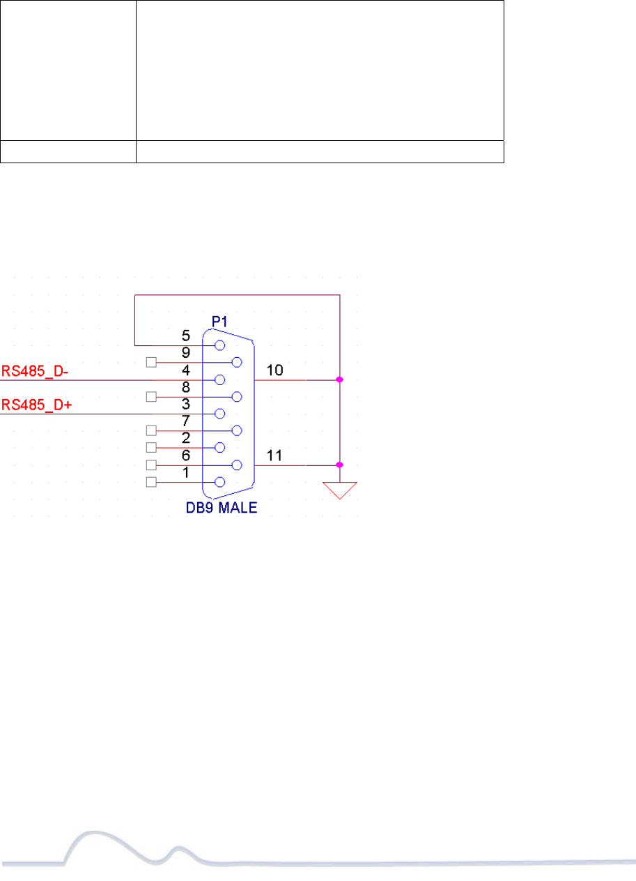
RS-485 DB9 Male pinout assignment
Figure-A2 RS-485 pin assignment (electrical characteristics)
• DB9_pin3 is RS-485_D+
• DB9_pin4 is RS-485_D-
• DB9_pin5 is GND
10 of 39
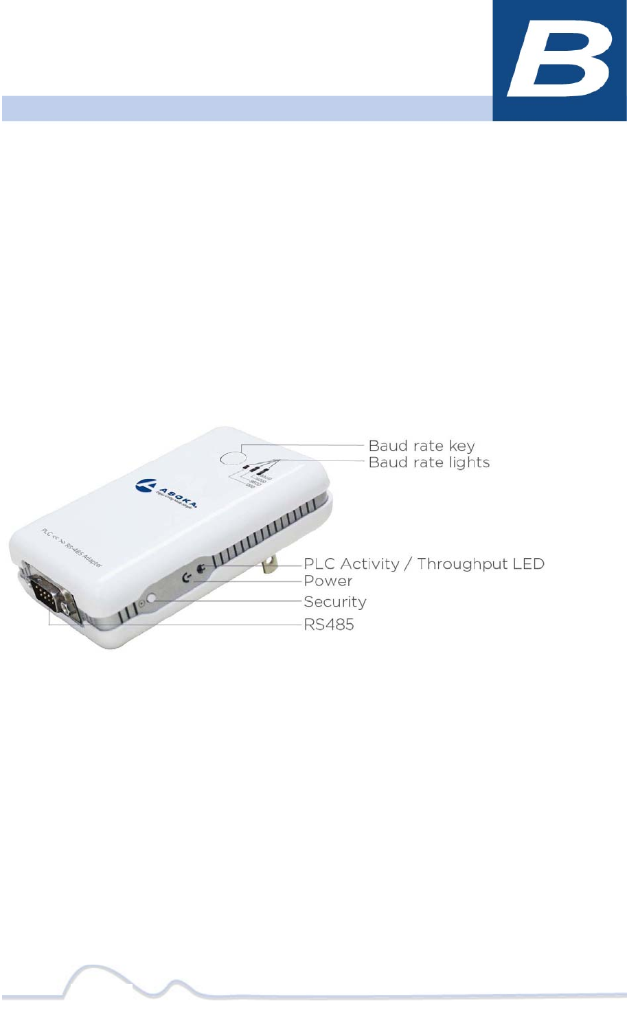
Components
Front Panel
Use the status lights on the front and side panel to verify connections.
Picture-B1
11 of 38
The following table describes the status light functions in the front and side panel:
Status Light State Indication
Power
Illuminated
Off
Device is powered on
Devices has no power
PLC Activity
Blinking
Red
Blinking
Yellow
Blinking Green
Low connection
Good connection
Excellent connection
Baud Rate
ON
Blinking Green
RS-485 Baud Rate Indicator Ready
Data transmitting on the RS-485 connector
Table-B2
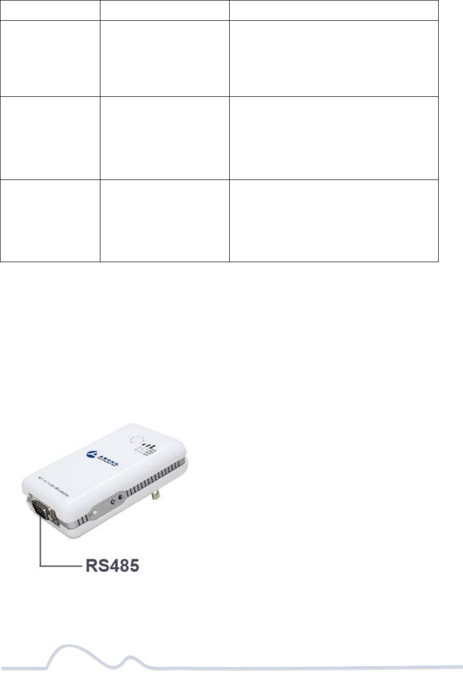
Bottom Side
The bottom panel of the PL7070-COM contains the following component:
• One RS-485 serial DB9 Male Connector
Picture-B2
12 of 38
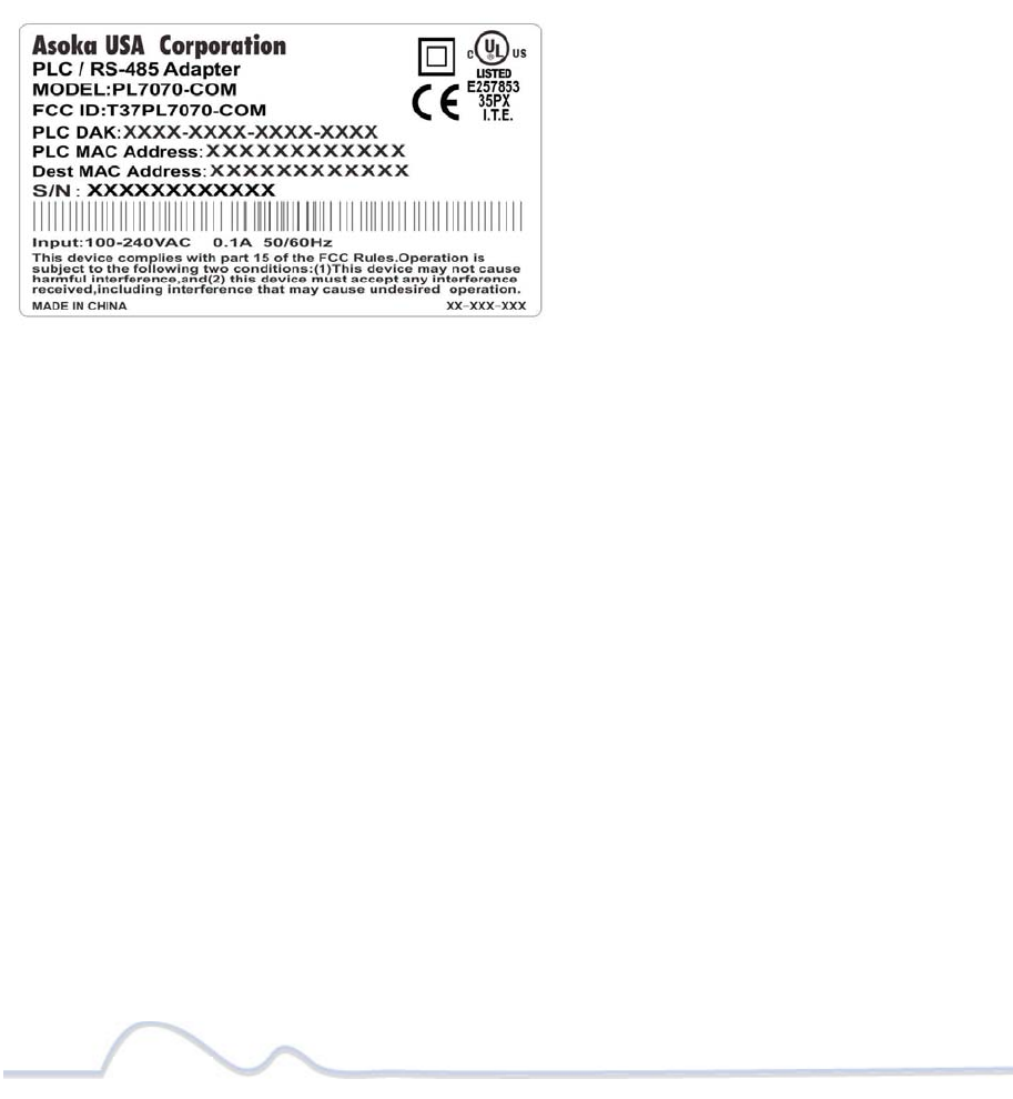
Rear Panel
The label on the rear panel of the PL7070-COM (PLC/RS-485) Adapter
contains the information listed below.
• MAC address
• Model number
• Part number
• Serial number
• PLC DAK
• PLC MAC
• Dest MAC
Note: Write this information down in your Warranty Support Information card for future
reference.
Figure-B1
13 of 38
Buttons
The PLC/RS-485 Adapter device has two hardware push buttons:
SECURITY (Network ID) button – All PLC/RS-485 Adapter devices have a default Network
Encryption Key (NEK) set to “HomePlugAV” allowing them to communicate to each other. The
SECURITY button allows you to set a devices to a randomized Network Encryption Key (NEK) for
maximum security. You can then set other devices to the same NEK by using their SECURITY
button. Only units with the same NEK can communicate to each other.
Baud Rate Key button and lights:
1. This button allows you to change the Baud Rate speed to 1200,9600 and 19200. The two
PL7070-com device baud rate should be same.
2. The Baud Rate light will start to flashing if data is passing through the RS-485 Connector.
3. Locking and Unlocking the Baud Rate:
• To lock a specific Baud Rate on the PL7070-COM adapter, simply press the Baud
Rate Key button for about 8 seconds. The correspond led will flash if the time
is reached, meaning that the baud rate is locked. To Unlock the Baud Rate,
press the Baud Rate Key button again for about 8 seconds; then it will unlock,
or powering OFF then ON will unlock the baud rate.
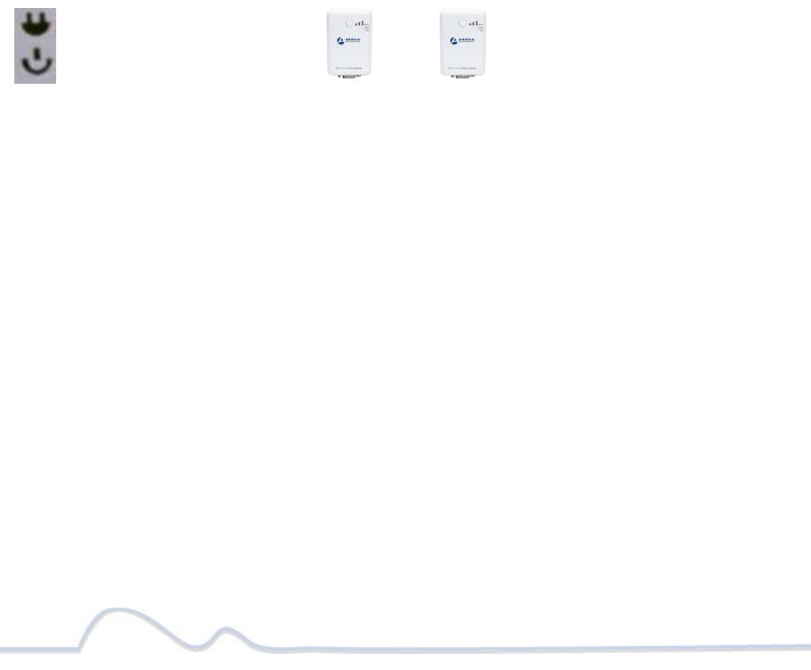
SETTING A RANDOMIZED PLC NETWORK PASSWORD (NEK)
1. Select a PL7070-COM Adapter (Device A) and plug into an AC outlet. The POWER light
indicator should be lit solid green.
a. Press the SECURITY button BRIEFLY (0.5 to 2 seconds) and release. The POWER light
should now be blinking green.
b. IMPORTANT: If the POWER light is not blinking green, repeat Step “a” until the
power light blinks green.
c. This unit is now ready to create a new randomized NEK (Net Encryption Key)
network. This unit will remain in this “adder” mode for about 2 minutes.
2. Select another PL7070-COM Adapter (Device B) and plug into a second outlet.
a. Press the SECURITY button BRIEFLY (0.5 to 2 seconds) and release. The POWER light
should now be blinking green.
b. IMPORTANT: If the power light is not blinking green, repeat Step “a” until the power
light is blinking green.
3. In about 15 seconds the POWER light will change from flashing green to solid green and
the PLC ACT (Power line Communication Activity) light will turn solid green (flashing
green when there is data traffic) indicating they are synchronized with the same NEK.
4. Congratulations, you are done!
DeviceADeviceB
PLCACTlight
Powerlight

14 of 38
Warranty
Asoka warrants that (a) the hardware components of the product will be free from defects in
materials and workmanship under normal use from the date of purchase when used within the
limits set forth in the Specifications section of the User Guide, and (b) the software components
will perform substantially in accordance with Asoka's published specifications for ninety (90)
days from the date of purchase, but does not warrant that the software will be error-free or
free of all defects.
Should a product fail to perform as described in the User Guide, it will be repaired or replaced
with the same or functionally equivalent product by Asoka, at its discretion, free of charge
provided that you: (a) return the failed product to an Asoka designated repair facility with
shipping charge prepaid, and (b) provide Asoka with proof of the original date of purchase.
Repaired or replacement products will be returned to you with shipping charges prepaid. Asoka
warrants any replaced or repaired product or component for the life of the product.
This warranty extends only to you, the original purchaser and is not transferable to any
subsequent purchasers.
This warranty does not apply if, in the judgment of Asoka, the product fails due to damage
from shipment, handling, storage, accident, abuse, misapplication or misuse, or if it has been
used or maintained in a manner not conforming to product manual instructions, has been
modified in any way, or has had any serial number removed or defaced. Repair by anyone other
than Asoka or an approved agent will void this warranty. The maximum liability of Asoka under
this warranty is limited to the purchase price of the

15 of 38
product covered by the warranty. Prior to returning any defective product, the purchaser or the
authorized merchant from whom the purchaser originally bought the product must obtain a
Return Material Authorization (RMA) number from Asoka. All defective products should be
returned to Asoka with shipping charges prepaid. Asoka will not accept collect shipments.
WHILE ASOKA HAS MADE EVERY EFFORT TO PROVIDE CLEAR AND ACCURATE TECHNICAL
INFORMATION ABOUT ITS PRODUCTS, ASOKA ASSUMES NO LIABILITY FOR ANY EVENTS ARISING
OUT OF THE USE OF THE TECHNICAL INFORMATION OR THE PRODUCT, EXCEPT AS SPECIFICALLY
PROVIDED IN THIS AGREEMENT OR AS REQUIRED BY LAW. THE WARRANTIES AND REMEDIES
STATED ABOVE ARE EXCLUSIVE AND IN LIEU OF ALL OTHERS, ORAL OR WRITTEN, EXPRESS OR
IMPLIED. ANY AND ALL OTHER WARRANTIES, INCLUDING IMPLIED WARRANTIES OF
MERCHANTABILITY, FITNESS FOR A PARTICULAR PURPOSE AND NON-INFRINGEMENT OF THIRD
PARTY RIGHTS ARE EXPRESSLY EXCLUDED. ASOKA SHALL NOT BE LIABLE, UNDER ANY
CIRCUMSTANCES, TO ANY PERSON OR ENTITY FOR ANY SPECIAL, INCIDENTAL, INDIRECT OR
CONSEQUENTIAL DAMAGES, INCLUDING WITHOUT LIMITATION, DAMAGES RESULTING FROM THE
USE OR MALFUNCTION OF THE PRODUCTS, LOSS OF PROFITS OR REVENUES, BUSINESS
INTERRUPTION, OR COSTS OF REPLACEMENT GOODS, EVEN IF ASOKA IS INFORMED IN ADVANCE
OF THE POSSIBILITY OF SUCH DAMAGES.

16 of 20
FCC Notice
FCC Statement
This equipment has been tested and found to comply with the limits for a Class B digital device,
pursuant to part 15 of FCC Rules. These limits are designed to provide reasonable protection
against harmful interference in a residential installation. This equipment generates and can
radiate radio frequency energy and, if not installed and used in accordance with the instructions,
may cause harmful interference to radio communications. However, there is no guarantee that
interference will not occur in a particular installation. If this equipment does cause harmful
interference to radio or television reception, which can be determined by turning the equipment
off and on, the user is encouraged to try to correct
The interference by one or more of the following measures:
Reorient or relocate the receiving antenna.
Increase the separation between the equipment and receiver.
Connect the equipment into an outlet on a circuit different from that to which the receiver is
connected.
Consult the dealer or an experienced radio/TV technician for help
This device complies with Part 15 of FCC Rules.
Operation is subject to the following two conditions:
This device may not cause harmful interference, and
This device must accept any interference received, including interference that may cause
undesired operation.

17 of 20
FCC RF Radiation Exposure Statement
Note: The manufacturer is not responsible for any radio or TV interference caused by
unauthorized modifications to this equipment. such modifications could void the user’s authority
to operate this equipment.

Asoka USA Corporation
2620 Augustine Drive Suite 230
230 Santa Clara, California 95054
USA Phone: (408) 550–8167
Fax: (408) 884–2390
www.asokatech.com
66-0386-01Rev.001
20 of 20