ASOKA USA PL9670-Q2 PlugLink-ETH-500 User Manual PL9670 Q2 manualx
ASOKA USA Corporation PlugLink-ETH-500 PL9670 Q2 manualx
Users Manual

PlugLink-ETH-500
User’s Guide
PL9670-Q2
QUICKFIND L
OCATOR
Contact
Information
Getting Help
Table of Contents
Installation
66-0376-01Rev.001

2 of 38
© 2012 Asoka USA Corporation
ALL RIGHTS RESERVED
Notice: No part of this publication may be reproduced or transmitted in any form or by any means, electronic or
mechanical, including photocopying and recording, or stored in a database or retrieval system for any
purpose without the express written permission of Asoka USA Corporation.
Asoka USA Corporation reserves the right to make changes to this user’s guide at any time without notice and
assumes no responsibility for its use. Asoka USA products and services can only be ordered under the terms and
conditions of Asoka USA Corporation's applicable agreements. All of the features described in this user’s guide
may not be currently available. Refer to the most recent product announcement for information about feature
and product availability.
This user’s guide contains the most current information available at the time of publication. When new and/ or
revised information becomes available, this entire user’s guide is updated and distributed to all registered users.
All company and product names mentioned herein are trademarks of their respective companies. Mention of
third-party products is for informational purposes only and constitutes neither an endorsement nor a
recommendation. Asoka USA Corporation assumes no responsibility with regard to the performance or use of
these products.
Revision
Date
Description
66-0376-01Rev.001 July.
2012
Preliminary Release
Changes in This Revision
• Not applicable (preliminary release)

3 of 38
Contact Information
For more information about the PlugLink-ETH-500 or any of Asoka’s other leading-edge
solutions, please contact us using any of the following methods:
z Voice calls: We welcome your calls Monday through Friday, from 9:00 am
to 5:00 pm Pacific Time at (408) 550-8167. Voice mail is available during non-business
hours. z Email: If you prefer, you can send information requests to our e-mail address:
sales@asokatech.com.
z Fax calls: You can also send your requests for information to our 24-hour fax
number: (408) 884-2390.
z Web site: Our Web site contains valuable information about our products,
solutions, and services. We encourage you to visit us at
http://www.asokatech.com.
Getting Help
Asoka USA backs its products with unparalleled customer service and technical support
for our valued customers.
Customer Service
Customer service, the customer-satisfaction arm of Asoka USA, is available Monday
through Friday, from 9:00 am to 5:00 pm Pacific Time, by calling (408) 550-8167 or
emailing custserv@asokatech.com
Technical Support
Technical support is available Monday through Friday, from 6:00 am to 6:00 pm
Pacific Time, by calling (408) 550-8173 or through email at support@asokatech.com.
Please provide the following information about the problem:
z Product name, model number, part number (if applicable) and serial number
z System configuration, including a description of the devices connected to your
PL9672
z The circumstances surrounding the error or failure
z A detailed description of the problem and what has been done to try to solve it

4 of 38
Table of Contents
1 Simple Installation ...................................................................... 5
Package Contents ................................................................................................... 5
Types of Connections ............................................................................................. 5
Simple Connection (Peer to Peer) ............................................................................ 6
Simple Broadband
Connection
................................................................................. 6
Other Connections .................................................................................................. 7
Finding a Suitable Location ..................................................................................... 7
Installing the Hardware .......................................................................................... 7
2 Advanced Configuration (Expert Users Only) ............................. 8
Installing the Software ............................................................................................ 8
3 Network Management ............................................................... 12
Viewing the Device Information (Profile) ................................................................. 12
Changing your device Name and Network Encryption Key (NEK) ............................... 13
DEVICE NETWORK ENCRYPTION KEY (NEK) ………………………………………………………..16
Resetting and Upgrading the PlugLink-ETH-500 ....................................................... 20
Prioritizing the Network Traffic ............................................................................... 21
Viewing the Network Statistics screen ..................................................................... 22
Viewing the Link screen ......................................................................................... 22
Viewing the LED screen ......................................................................................... 24
Rescanning your Powerline Network ....................................................................... 24
Manually Resetting the Firmware and Network ID (NID) .......................................... 25
4 Troubleshooting ........................................................................ 26
A Specifications ............................................................................ 28
B Components .............................................................................. 30
C Warranty ................................................................................... 34
D FCC Notice................................................................................. 36

5 of 38
Simple Installation
Congratulations on your purchase of the PlugLink-ETH-500 !
This adapter allows you to network your home or office by plugging directly into an
electrical outlet. With your PlugLink-ETH-500, you can easily share your high-speed
Internet, mp3s, video, and gaming throughout the home or office.
This manual describes how to connect your PlugLink-ETH-500 to a PC or cable/DSL
Router.
Package Contents
z PlugLink-ETH-500(PL9670-Q2)
z 6-foot Ethernet cable
z Quick Installation Guide
z Installation Resource CD (for advanced users only)
z Warranty and Support Information Card
If any of the parts are incorrect, missing, or damaged, contact the retailer
where you made your purchase. Keep the carton, including the original packing
materials, in case you need to return the unit for repair.
Types of Connections
This section describes what you need to do to before installing the PlugLink-ETH-500.
You can set up a home or an office network or compliment your existing network by
connecting to any device with a 10BaseT/100BaseT /1000BaseT Ethernet- capable
device.
6 of 38
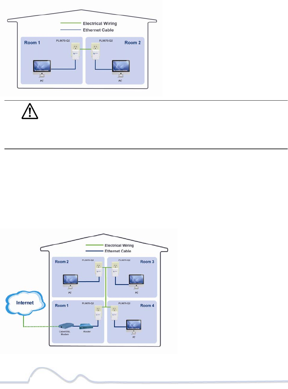
Simple Connection (Peer to Peer)
To share a simple connection between computers, attach one PL9670-Q2 device to
each computer.
NOTE: Do not connect the PlugLink-ETH-500 into a power strip, extension
cord, un-interruptible power supply (UPS), or surge protector. This may prevent
the unit from working properly or degrade the network performance.
Simple Broadband
Connection
The following items are needed to share a Broadband connection with computers:
z One (1) PL9670-Q2 device attached to a standard cable, DSL, or wireless router;
z One (1) PL9670-Q2 device attached to each computer;
7 of 38
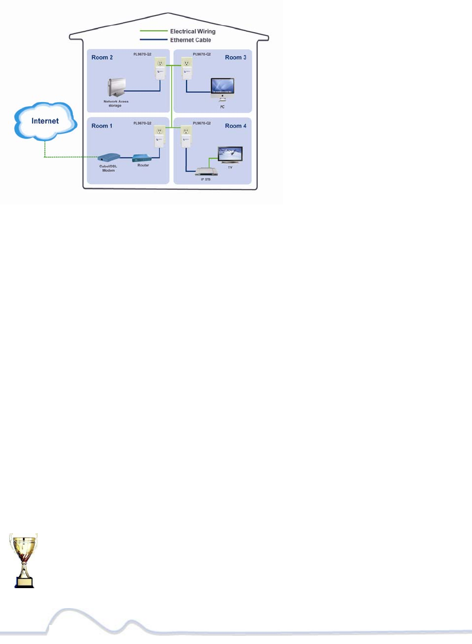
Other Connections
You can also use the PlugLink-ETH-500 with other Ethernet enabled devices, such as
IP Cameras, IP set top box, game consoles, etc.“Up to eight (8) PL9672 can be placed
on the same PLC (Powerline Communication) network.”
Finding a Suitable Location
Find a suitable location to install your PlugLink-ETH-500 . Where you install the units
can affect their performance. Find a location that is:
z Acceptable temperature and humidity ranges.
z Free of strong electromagnetic field generators (such as motors), vibration, dust,
and direct exposure to sunlight.
z An electrical outlet for your PlugLink-ETH-500 . Outlet must be within six feet (1.82
meters) of the device you are connecting to.
Installing the Hardware
Connect each of your PlugLink-ETH-500 .
1. Connect the unit into a nearby wall outlet (Do not plug the adapter into a power
strip).
2. Connect the enclosed Ethernet cable to the Ethernet port of the unit.
3. Connect the other end of the cable to the Ethernet port of the PC or device.
Congratulations! You have completed the installation of the
PL9672 for normal use.
8 of 38
Advanced Configuration
(Expert Users Only)
This chapter provides information on installing and setting up the PlugLink-ETH-500.
NOTE: Do not connect the PlugLink-ETH-500 into a power strip, extension cord,
un-interruptible power supply (UPS), or surge protector. This may prevent the unit from
working properly or degrade the network performance.
Installing the Software
Following are software installation procedures for advanced users.
NOTE: Software installation is not required for normal use. The utility is used to
change the security settings and view information about the network.
1. Insert the enclosed Installation Resource CD into your CD-ROM drive If the PlugLink-
ETH-500 Installation Utility does not appear within 30 seconds, select your CD-ROM
drive and double-click the Setup.exe icon to start the Installation Utility.
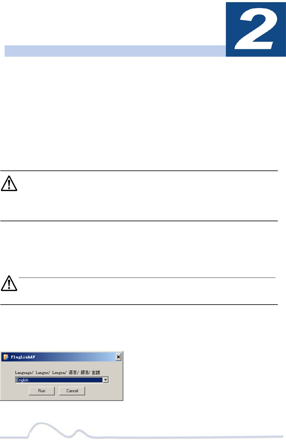
2. Select the language preference, and click the Run button.
9 of 38
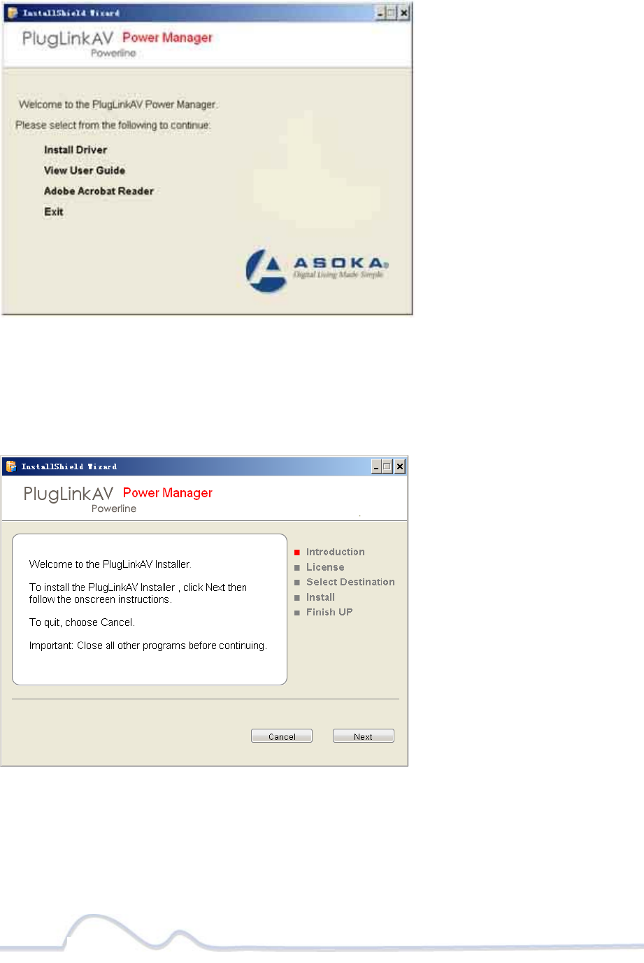
3. In the Start screen, click Install Driver to start the installation.
4. In the Welcome screen of the screen of the wizard, click Next to begin the
installation.
10 of 38
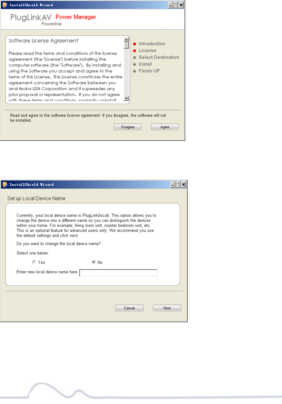
5. Read the End User Software License Agreement, and if you agree, click the Agree
button to continue the installation.
6. To change the name of the PlugLink AV unit, select Yes, and enter a name in the
text field. Otherwise, select No. Click Next to advance to the next screen.
11 of 38
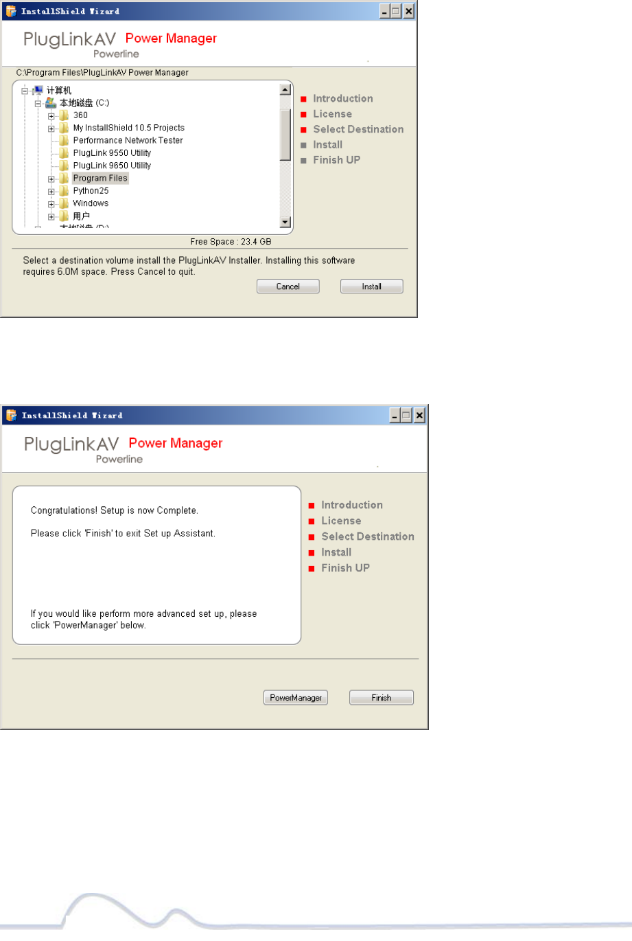
7. Select the location where you want to install the drivers and software and click the
Install button.
8. When the installation of the PlugLink drivers and software is complete, you can use
Power Manager Utility for advanced configuration of your PL9672 unit. Click Finish
to finish the installation wizard.
12 of 38
Network Management
The PlugLink Power Manager utility software allows you to manually configure a
PlugLink HD AV Adapter that is directly connected to your Personal Computer or to
any PlugLink Adapters that are remotely residing on your PlugLink Home network.
NOTE: The Power Manager Utility software is for all Asoka
PlugLink devices.
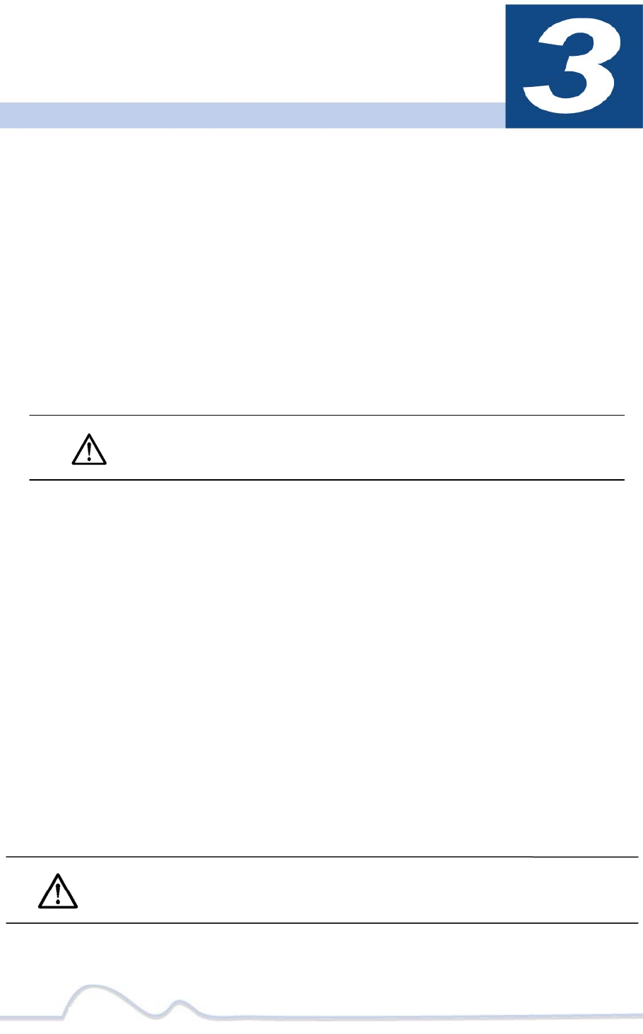
Viewing the Device Information (Profile)
Run the PlugLink Power Manager and use the Profile screen to view information
on your PlugLink device attached directly to your PC and other PlugLink
devices on your network.
The Profile screen displays the following information:
• Device Name
• MAC Address
• Firmware version of your devices
• Estimated device transmission rate
To refresh the list of your PlugLink devices, click the Rescan
button.
NOTE: Devices set up with a different Network Encryption Key (NEK)
also known as the network password will NOT appear on this list.
13 of 38
Profile Screen
Changing your device Name and Network Encryption
Key (NEK)
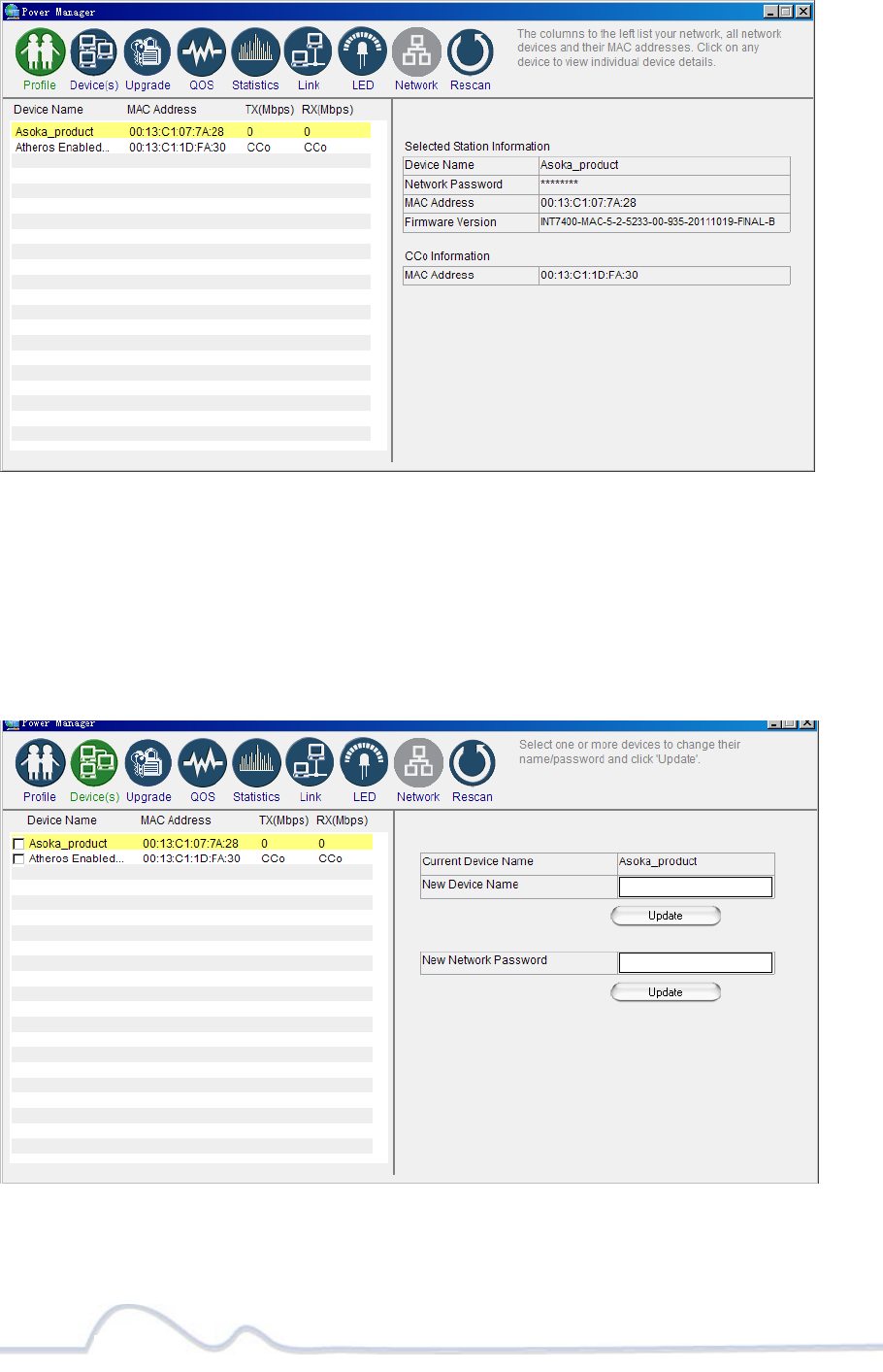
Use the Device(s) Screen to change your local and remote device name, also to change
your local and remote device Network Encryption Key (NEK) (also known as the
Network Password).
Device(s) Screen
14 of 38
DEVICE NAME
Changing your local device name:
1. Connect your PlugLink adapter to your PC. For instructions on how to connect
your PlugLink to your PC, please refer to page 7 (Installing the Hardware).
2. Run the PlugLink Power Manager software. If you have not installed the PlugLink
Power Manager software onto a PC, please refer to page 8 (Installing the
Software).
3. From the Power Manager main menu, click “Device(s)”.
4. A list of PlugLink devices will appear on the left side of your Power Manager
screen. Your Local Device will always be the first device in the list by default.
5. Select your local device, by clicking on the first device MAC Address from the
list. Make sure that the device selected is highlighted in yellow. NOTE: It is not
necessary to check the box to the left of the Device Name.
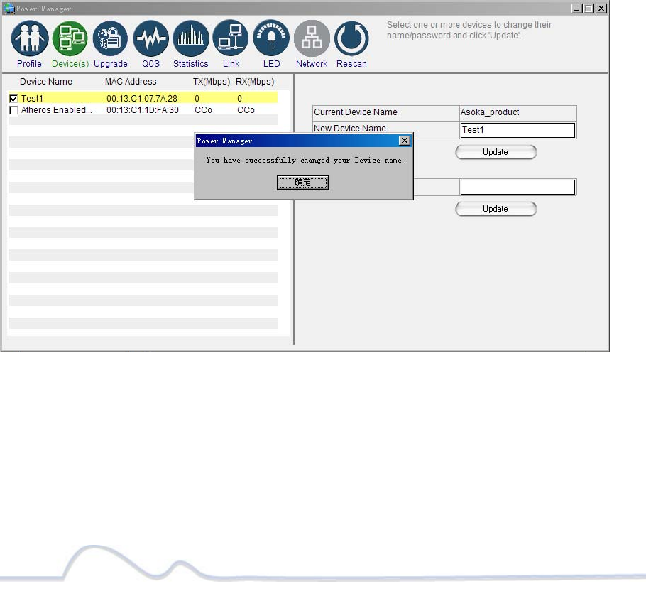
6. Enter the new name in the New Device Name field. The new name must be at
least 4 characters long and can’t have spaces.
7. Click “Update” to update the new name.
8. If the new name was accepted, the message “You have successfully changed
your Device name.” will appear.
9. Congratulations, you have successfully changed your local device name.
Changing your local device name
15 of 38
Changing your remote device name:
1. Connect your PC to one of your PlugLink adapters. For instructions on how to
connect your PlugLink to your PC, please refer to page 7 (Installing the
Hardware).
2. Run the PlugLink Power Manager software. If you have not installed the PlugLink
Power Manager software onto a PC, please refer to page 8 (Installing the
Software).
3. From the Power Manager main menu, click “Device(s)”.
4. A list of PlugLink devices will appear on the left side of your Power Manager
screen. Your Remote Devices will always appear under the first device in the list
by default.
5. Select your remote device, by clicking on the device MAC Address from the list.
Make sure that the device selected is highlighted in yellow. NOTE: It is not
necessary to check the box to the left of the Device Name.
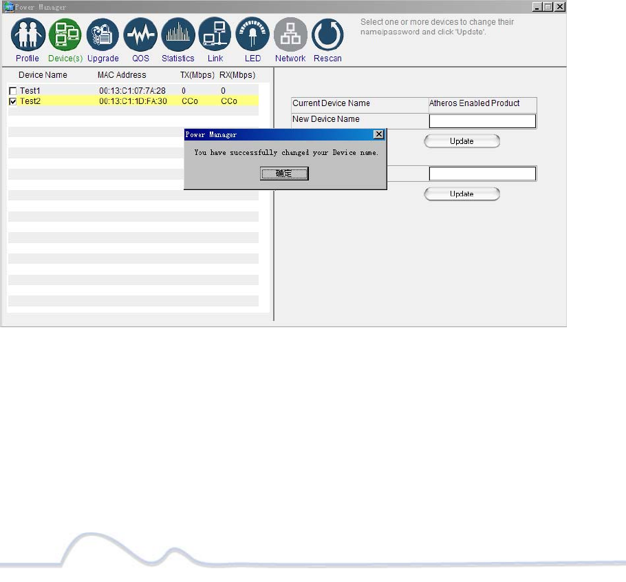
6. Enter the new name in the New Device Name field. The new name must be at
least 4 characters long and can not have spaces.
7. Click “Update” to update the new name.
8. If the new name was accepted, the message “You have successfully changed
your Device name.” will appear.
9. Congratulations, you have successfully changed your remote device name.
Changing your remote device name
16 of 38
DEVICE NETWORK ENCRYPTION KEY (NEK)
Understanding the Network Encryption Key: The Network Encryption Key (NEK) is
similar to a domain name or work group. Only those devices encrypted with the
same domain name or work group, will have access to your Powerline Network. All
Asoka PlugLink adapters are encrypted with the same default Network
Encryption Key. The default Network Encryption Key is: HomePlugAV.
It is recommended to change your device default Network Encryption Key (NEK) to
secure your Powerline Network from unauthorized access; especially if you live in
an Apartment building.
Use caution when changing your device Network Encryption Key (also known as the
Network Password). If you change the Network Encryption Key on one device, you
must change the Network Encryption Key on all your PlugLink adapters to the
new Network Encryption Key.
You can change your device Network Encryption Key by:
¾ Using the PlugLink Power Manager described in this section “Changing
your local device Network Encryption Key” (bellow).
¾ Using the Network ID (SECURITY) button described on page 32 “SETTING A
RANDOMIZED NETWORK PASSWORD”.
Changing your local device Network Encryption Key (NEK):
WARNING: If you change your local device Network Encryption Key
(Network Password) your local device will no longer be able to
communicated with all your other PlugLink adapters. You must
change the Network encryption key on all your PlugLink adapters to
the new Network Encryption Key in order for them to communicate.
1. Connect your PlugLink adapter to your PC. For instructions on how to connect
your PlugLink to your PC, please refer to page 7 (Installing the Hardware).
2. Run the PlugLink Power Manager software. If you have not installed the PlugLink
Power Manager software onto a PC, please refer to page 8
(Installing the Software).
3. From the Power Manager main menu, click “Device(s)”.
4. A list of PlugLink devices will appear on the left side of your Power
Manager screen. Your local Device will always be the first device in the list
by default.
17 of 38
5. Select your local device, by clicking on the first device MAC Address from
the list. Make sure that the device selected is highlighted in yellow.
IMPORTANT: You must check the box to the left of the Device Name.
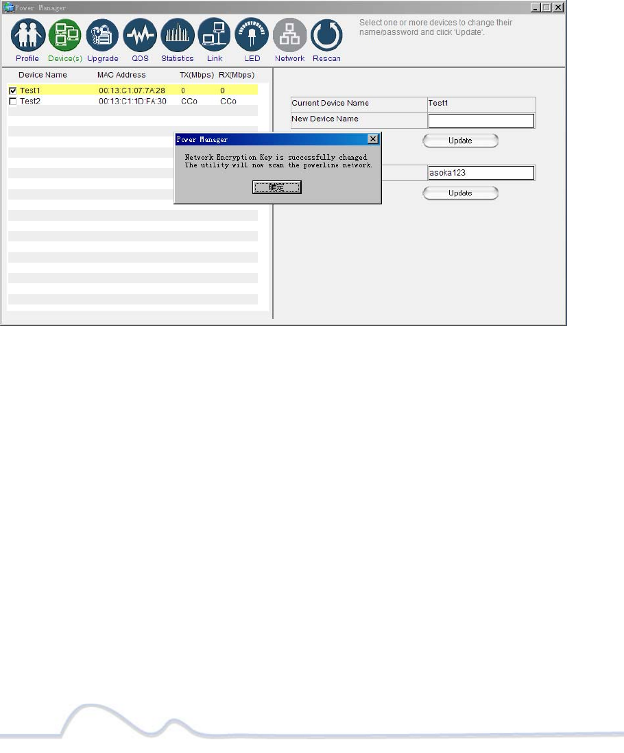
6. Enter the new Network Encryption Key (NEK) in the New Network Password
field. The new Network Password must be at least 8 characters long and
can not have spaces.
7. Click “Update” to update the new Network Password.
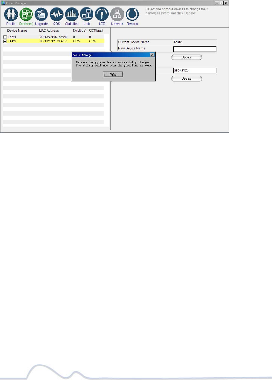
8. If the new Network Password was accepted, the message “Network
Encryption Key is successfully changed. The utility will now scan the
powerline network” will appear.
9. Congratulations, you have successfully changed your local device Network
Password.
Changing your local device Network Encryption Key (NEK)
18 of 38
Changing your remote device Network Encryption Key (NEK):
WARNING: If you change your remote device Network Encryption Key (Network
Password) your remote device will no longer be able to communicated with all
your other PlugLink adapters. You must change the Network encryption key on
all your PlugLink adapters to the new Network Encryption Key in order for them
to communicate.
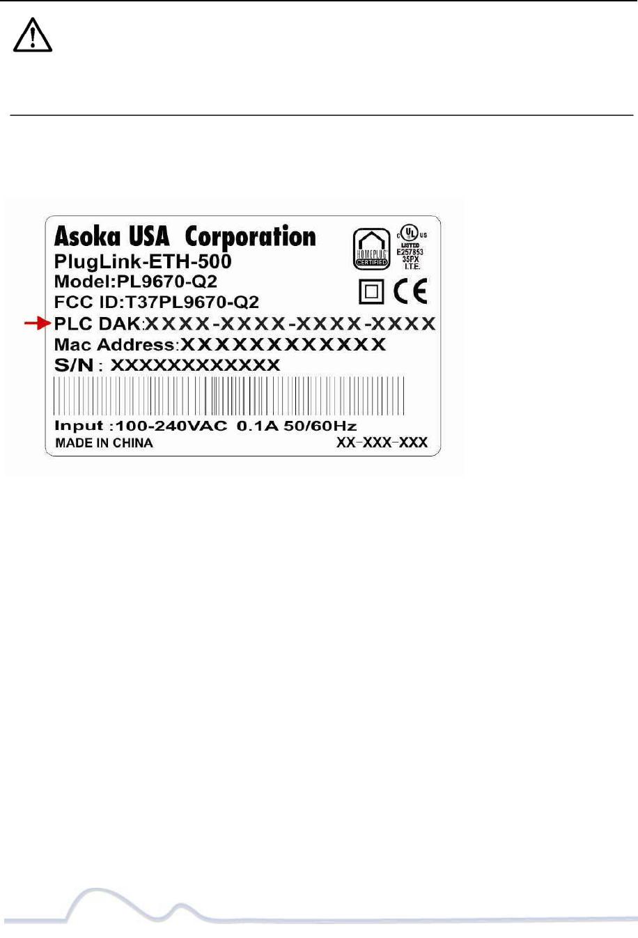
NOTE: When changing your remote device NEK, you will be prompted to enter the
selected device 16-digit Password at least once. You can find the device password on
the label. See image bellow.
1. Connect your PC to one of your PlugLink adapters. For instructions on
how to connect your PlugLink to your PC, please refer to page 7
(Installing the Hardware).
2. Run the PlugLink Power Manager software. If you have not installed the PlugLink
Power Manager software onto a PC, please refer to page 8 (Installing the
Software).
3. From the Power Manager main menu, click “Device(s)”.
4. A list of PlugLink devices will appear on the left side of your Power Manager
screen. Your Remote Devices will always appear under the first device in the list
by default.
5. Select your remote device, by clicking on the device MAC Address from the list.
Make sure that the device selected is highlighted in yellow. IMPORTANT: You
must check the box to the left of the Device Name. If you are prompted; enter
the 16 digits remote device password (Example Password: AIAI-AFZO-FMP-FLUI).
See image above for your reference.
6. Enter the new Network Encryption Key (NEK) in the New Network Password field.
The new Network Password must be at least 8 characters long and
Can’t have spaces.
7. Click “Update” to update the new Network Password.
19 of 38
8. If the new Network Password was accepted, the message “Network Encryption
Key is successfully changed. The utility will now scan the Powerline network”
will appear.
9. Congratulations, you have successfully changed your local device Network
Password.
Changing your remote device Network Encryption Key (NEK)
20 of 38
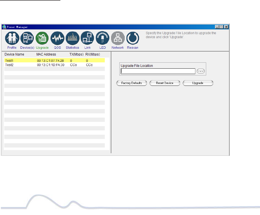
Resetting and Upgrading the PlugLink-ETH-500
Run the PlugLink Power Manager and use the Upgrade screen to:
z Reset your PlugLink-ETH-500 to Factory Defaults
z Reset (Reboot) your PlugLink-ETH-500
z Upgrade the Firmware
How to reset your PlugLink-ETH-500 to its Factory Defaults, reboot and Upgrade the firmware.
1. Connect your PC to one of your PlugLink adapters. For instructions on how to
connect your PlugLink to your PC, please refer to page 7 (Installing the
Hardware).
2. Run the PlugLink Power Manager software. If you have not installed the PlugLink
Power Manager software onto a PC, please refer to page 8 (Installing the
Software).
3. From the Power Manager main menu, click “Upgrade”.
4. A list of PlugLink devices will appear on the left side of your Power Manager
screen.
5. Select the device, by clicking on the device MAC Address from the list.
6. Select the option button that you want to perform (Factory Default, Reset
Device or Upgrade).
NOTE: Asoka may, from time to time, create new firmware for your device. Visit
www.asokatech.com for the latest firmware. – Resetting the PlugLink to its Factory
Defaults, will reset the Network Encryption Key (NEK or Network Password) to
HomePlugAV.
Upgrade Screen
21 of 38
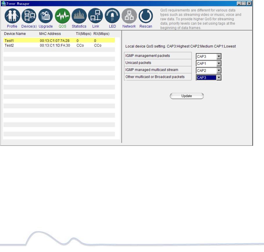
Prioritizing the Network Traffic
Use the QoS screen to prioritize your traffic through the device. QoS requirements are
different for various data types such as streaming video or music, voice and raw data.
To provide higher QoS for streaming data, priority levels can be set using tags at the
beginning of data frames.
The QoS level settings are: CAP3: Highest CAP2: Medium and CAP1: Lowest.
• IGMP management packets: (Default to CAP3) – Sets the channel
access priority for IGMP group management frames.
• Unicast packets: (Default to CAP1) – Sets the default channel
access priority for Unicast frames not matching any other
classification or mapping.
• IGMP managed multicast stream: (Default to CAP2) – Sets the
default channel access priority for stream data belonging to a
snooped IGMP multicast group.
• Other multicast or Broadcast packets: (Default to CAP3) – Sets the
default CAP for multicast frames not in a snooped group and for
broadcast frames.
QoS Screen
22 of 38
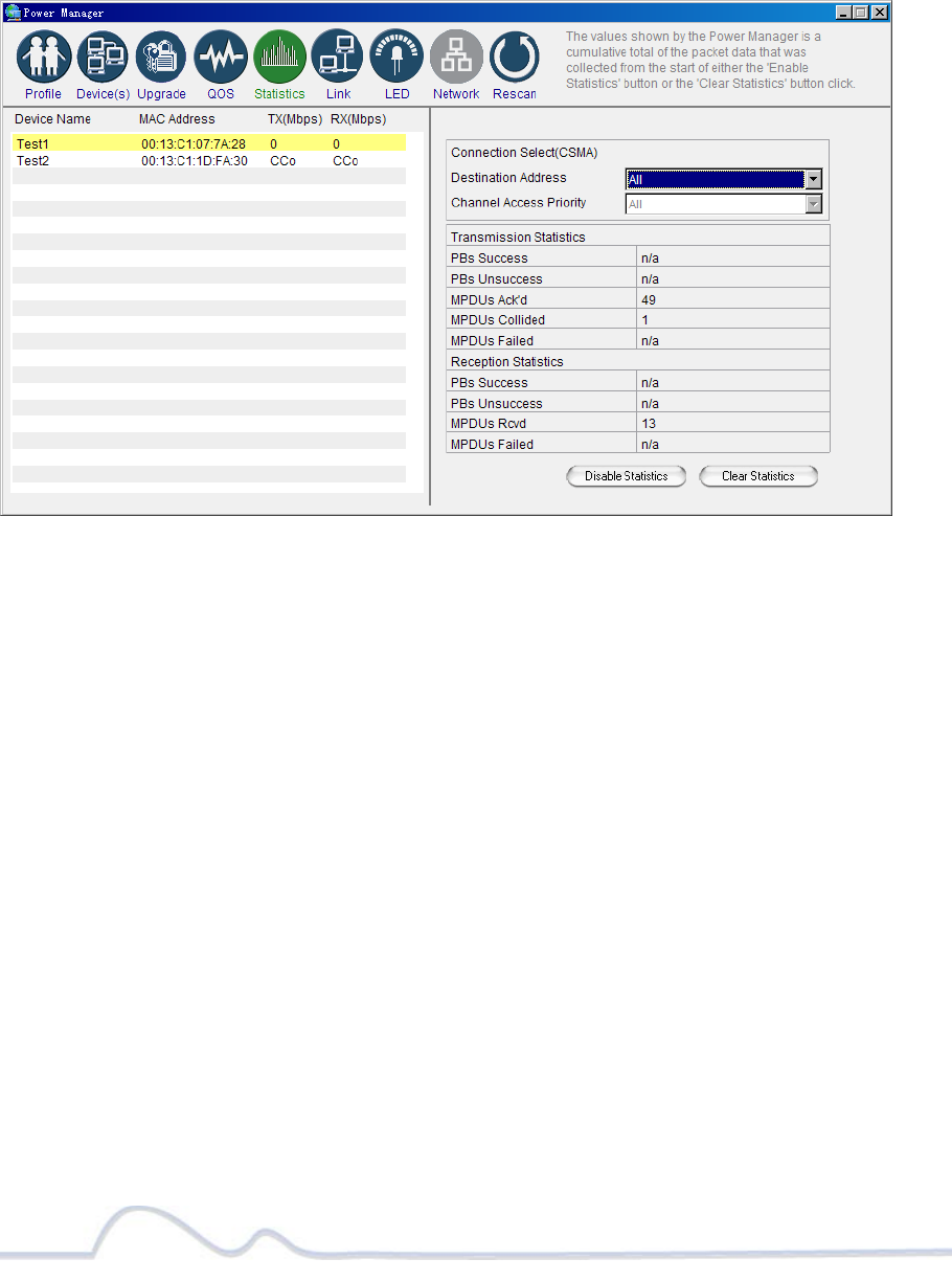
Viewing the Network Statistics screen
The Statistics screen shows information on HomePlug packets that are transmitted and
received by the devices in your network. To enable this function, click Enable
Statistics. The value shown by the Power Manager is a cumulative total of the packet
data that was collected from the start of the “Enabled Statistics” button.
Statistics screen
Viewing the Link screen
The Link Screen has two sub-screens that provide information about your Ethernet and
HomePlug connection.
Ethernet Sub Screen:
The Ethernet sub screen shows the Ethernet connection speed of the local and
destination devices in your network. You can select the destination device in the
Destination Address drop down menu. Click the Retrieve button to get the information.
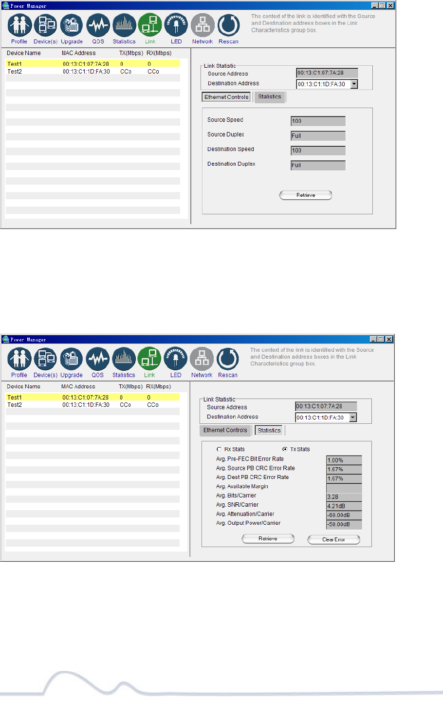
23 of 38
Link Screen; Ethernet Sub-Screen
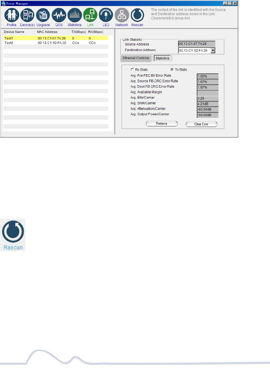
Statistics Sub Screen:
Use the Statistics sub screen to view statistical information about your
connection between a source device and a specific destination device in your
network. Click the Retrieve button to start accumulating the statistical information.
Link Screen; Statistics sub screen
24 of 38
Viewing the LED screen
This is the LED Manager tab. It allows you to configure the LED functionality threshold.
IMPORTANT: YOU CAN ONLY ENTER WHOLE NUMBERS DIVISIBLE BY 4. Example: 100, 80,
60 (no odd numbers) etc. If you enter a value that is not divisible by 4; then you will
get the message: “The value Yellow or Green must divide by 4!”
LED screen
Rescanning your Powerline Network
Use the Rescan button to scan for your Powerline devices under the same Network
Password in your HomePlug network. This option refreshes the information on your
Power Manager.
25 of 38
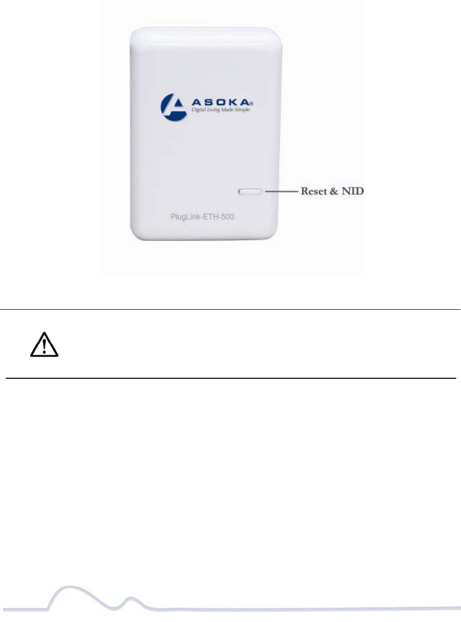
Manually Resetting the Firmware and Network ID (NID)
You can use the buttons on your PlugLink device to reset the firmware back to its
factory defaults, and to create or associate your PlugLink-ETH-500 to a randomized
Powerline Network. For details on how to use the buttons on your PlugLink adapter,
please refer to page 32 of this manual.
Note: The PlugLink device must be plugged into an electrical outlet when
using these buttons. If you have questions, please contact Asoka USA
Technical Support at (408) 550-8173.

26 of 38
Troubleshooting
Following are solutions to a few situations you might encounter. If you do not find a
solution in this chapter, contact Asoka USA Technical Support by phone at (408) 550-
8173 or through email at support@asokatech.com.
Symptom: I can't connect to anything and there are no lights activated on my PL9670-
Q2.
Solution:
Unplug the device from the electrical outlet in question.
Locate another available outlet in your home.
Test the outlet by plugging in another electrical device such as a lamp or radio.
Plug the PL9670-Q2 into the working electrical outlet.
Check to see if the lights work
If the above does not work, the device might be defective.
Please contact Technical Support for instructions on returning the device for repair or
replacement.
Symptom: Some of my devices cannot connect to the Internet or other computers in
my network. The lights seem to be functionally normally.
Solution #1:
Re-Initialize the PL9670-Q2 device.
Unplug the PL9670-Q2 from the electrical outlet.
Disconnect the Ethernet cable from the device
Plug the PL9670-Q2 back into the electrical outlet.
Reconnect the Ethernet cable.

27 of 38
Solution #2:
The Network Encryption Key (NEK) may not be correct on your devices.
Reset the Network Encryption Key using the Factory Reset button located on the
bottom of your PL9670-Q2 device. This will reset the NEK back to the default of
HomePlug.
Test your connection again. If this still does not work, perform the factory reset on all
of your other PL9670-Q2 devices in your network.
Solution #3:
It is possible some outlets in your home are not connect together.
Unplug the PL9670-Q2 from the current electrical outlet.
Locate another outlet in the home.
Plug the PL9670-Q2 into that outlet.
Attach a computer to the PL9670-Q2.
Open the Power Manager Utility (located on the enclosed CD).
Under the Profile button, check if your PL9670-Q2 is displayed (it Will be the first) and
see if your other PL9670-Q2 devices can be seen. If you can see other devices under
the Profile screen, your PL9670-Q2 device is functioning properly.
Solution #4:
Your broadband connection may have stopped working.
Power down your broadband router and/or DSL/cable modem (if applicable) for about
30 seconds and then power them back on.
If this step fails, please contact your ISP for assistance.

28 of 38
Specifications
This appendix lists the specifications for your PL9670-Q2.
Standards Compliance: •HomePlug® AV • IEEE 802.3, IEEE 802.3x, IEEE 802.3u,IEEE1901
Software Utility
System Requirements:
Microsoft Windows® 98 SE, 2000, ME, XP, Vista and windows 7(32bit)
Windows 7 (64-bit) ; operating systems
Network Protocol: TCP/IP, CSMA/CA, TDMA (supported in the future)
Network Interface: Two-ports 10/100 Mbps Ethernet (RJ-45)
PHY-Rate: Up to 500 Mbps
Distance: Over 300 meters
Operating Frequency: 2 to 70 MHz
Modulation Schemes: • Orthogonal Frequency Division Multiplexing (OFDM) • QAM
4096/1024/256/64/16 •QPSK •BPSK
EMI and Safety: • FCC Part 15 Class B •UL (US and Canada) •CE
Additional Protocols: • Forward Error Correction (FEC) • Automatic Channel Adaptation
Power Supply: • US Version: 100-120VAC • UK/EU Version: 220-240VAC
Surge Energy Rating: 4KV
Power Rating: • US Version: 120VAC 0.1A max, 60Hz • UK/EU Version:
220-240VAC 0.08A max, 50Hz
Security: 128-bit AES

29 of 38
Environmental
Specifications:
• Operating temperature: 32°F to 113°F (0°C to 45°C) • Operating
humidity: 10% to 85% Non-condensing • Storage temperature: -4°F to
158°F (-20°C to 70°C) • Storage humidity:
5% to 90% Non-condensing
Quality of Service: •ToS • 802.1q • TDMA (supported in the future)
Warranty: lifetime
30 of 39
Components
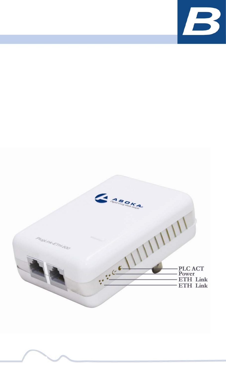
Front Panel
Use the status lights on the front panel to verify connections.
31 of 39
The following table describes the status light functions in the front panel:
Status Light State Indication
Power
Illuminated
Off
Red and Green
illuminate alternately
Device is powered on
Devices has no power
Stand by mode (After 3 minutes no link)
PLC Activity Blinking
Red
Blinking
Yellow
Blinking Green
Off
low connection
good connection
excellent connection
no connection
Eth Link Illuminated
Blinking
Off
Ethernet connectivity
Ethernet traffic
No Ethernet connectivity
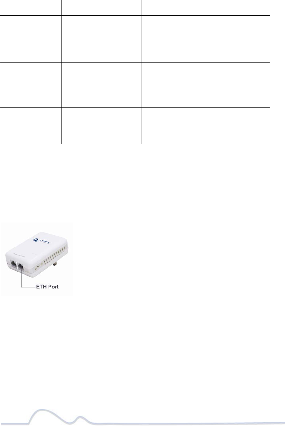
Bottom Panel
The bottom panel of the PL9670-Q2 contains the following components:
RJ-45 Ethernet port
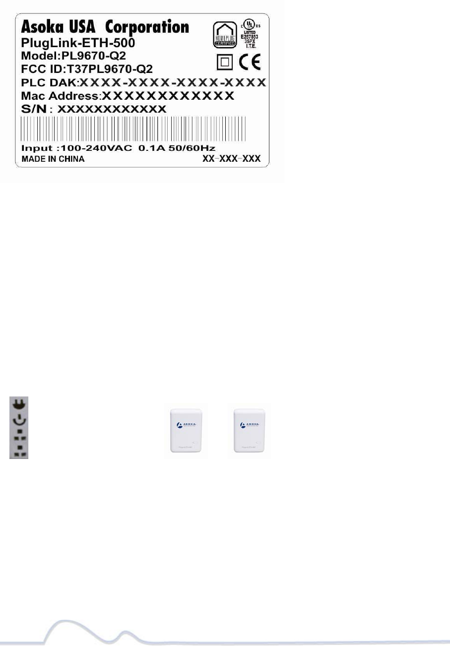
The label on the rear panel of the PlugLink-ETH-500 contains the information
listed below.
MAC address
Model number
Part number
Serial number
PLC DAK
32 of 38
Note: Write this information down in your Warranty Support Information card for future
reference.
Buttons
The PlugLink-ETH-500 device has two hardware push buttons:
FW RST (FirmwareDefaultReset)button – Resets the PlugLink-ETH-500 back to factory default
settings. Press and hold the button with a pin or sharp object for about 2 seconds until you see
the lights on the device flash briefly.
SECURITY (Network ID) button – All PlugLink-ETH-500 devices have a default password
Network Encryption Key (NEK) set to “HomePlugAV” allowing them to communicate to each
other. The SECURITY button allows you to set a devices’ password to a randomized Network
Encryption Key (NEK) for maximum security. You can then set other devices to the same NEK by
using their SECURITY button. Only units with the same NEK can communicate to each other.
SETTING A RANDOMIZED NETWORK PASSWORD
Select a PlugLink-ETH-500 (Device A) and plug into an AC outlet. The POWER light indicator
should be lit solid green.
Press the SECURITY button BRIEFLY (1 second) and release. The POWER light should now be
blinking green.
IMPORTANT: If the POWER light is not blinking green, repeat Step “a” until the power light
blinks green.
This unit is now ready to create a new randomized NEK (Net Encryption Key) network. This unit
will remain in this “adder” mode for about 2 minutes.
Select another PlugLink-ETH-500 (Device B) and plug into a second outlet.
Press the SECURITY button BRIEFLY (1 second) and release. The POWER light should now be
blinking green.
DeviceADeviceB
PLCACTlight
Powerlight
Ethernetlight
Ethernetlight
33 of 38
IMPORTANT: If the power light is not blinking green, repeat Step “a” until the power light is
blinking green.
In about 15 seconds the POWER light will change from flashing green to solid green and the PLC
ACT (Power line Communication Activity) light will turn solid green (flashing green when there
is data traffic) indicating they are synchronized with the same NEK.
Congratulations, you are done!
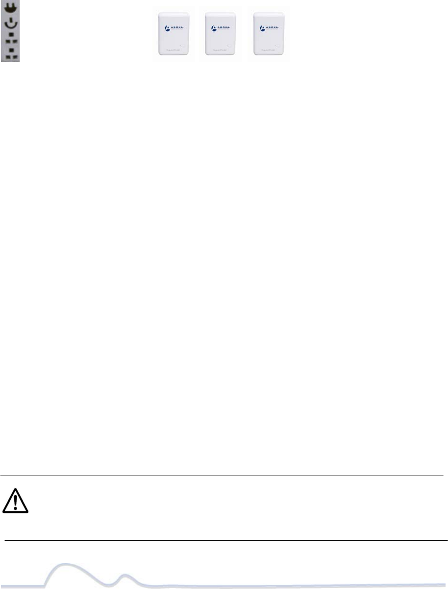
ADDING A THIRD OR MORE PLUGLINK HD AV DEVICES
Plug your new PlugLink-ETH-500 (Device C) into an AC outlet. The POWER light indicator should
be lit solid green.
Press the SECURITY button BRIEFLY (1 second) and release. The POWER light should now be
blinking green.
IMPORTANT: If the POWER light is not blinking green, repeat Step “a” until the power light is
blinking green.
This unit is now ready to join the existing HD AV network. This unit will remain in this “adder”
mode for about 2 minutes.
From your existing devices (either device A or device B) press the SECURITY button BRIEFLY (1
second) then release. The POWER light should now be blinking green.
IMPORTANT: If the power light is not blinking green, repeat Step “2” until the power light is
blinking green.
In about 15 seconds the POWER light will change from flashing green to solid green and the PLC
ACT (Power line Communication Activity) light will turn solid green (flashing green when there
is data traffic) indicating they are synchronized with the same NEK.
To add more PlugLink devices; simple repeat this process per device.
Congratulations, you are done!
Notes:
The other devices already in the Power line network with the proper NEK are not
affected and do not need to be reconfigured.
If you disconnect power from any device, its NEK value will remain and will not
default back to “HomePlugAV” NEK.
An adapter can only generate a private key once. To replace a private key, first
reset the unit back to its factory defaults by pressing the Firmware Default Reset
(FW RST) button for 1 second, then follow the procedure above
The use of the SECURITY (Network ID) button is optional. You may also use the
application software described in the manual to set NEK's as well.
DeviceADeviceBDeviceC
PLCACTlight
Powerlight
Ethernetlight
Ethernetlight

34 of 38
Warranty
Asoka warrants that (a) the hardware components of the product will be free from
defects in materials and workmanship under normal use from the date of purchase
when used within the limits set forth in the Specifications section of the User Guide,
and (b) the software components will perform substantially in accordance with Asoka's
published specifications for ninety (90) days from the date of purchase, but does not
warrant that the software will be error-free or free of all defects.
Should a product fail to perform as described in the User Guide, it will be repaired or
replaced with the same or functionally equivalent product by Asoka, at its discretion,
free of charge provided that you: (a) return the failed product to an Asoka designated
repair facility with shipping charge prepaid, and (b) provide Asoka with proof of the
original date of purchase. Repaired or replacement products will be returned to you
with shipping charges prepaid. Asoka warrants any replaced or repaired product or
component for the life of the product.
This warranty extends only to you, the original purchaser and is not transferable to any
subsequent purchasers.
This warranty does not apply if, in the judgment of Asoka, the product fails due to
damage from shipment, handling, storage, accident, abuse, misapplication or misuse,
or if it has been used or maintained in a manner not conforming to product manual
instructions, has been modified in any way, or has had any serial number removed or
defaced. Repair by anyone other than Asoka or an approved agent will void this
warranty. The maximum liability of Asoka under this warranty is limited to the
purchase price of the

35 of 38
product covered by the warranty. Prior to returning any defective product, the
purchaser or the authorized merchant from whom the purchaser originally bought the
product must obtain a Return Material Authorization (RMA) number from Asoka. All
defective products should be returned to Asoka with shipping charges prepaid. Asoka
will not accept collect shipments.
WHILE ASOKA HAS MADE EVERY EFFORT TO PROVIDE CLEAR AND ACCURATE TECHNICAL
INFORMATION ABOUT ITS PRODUCTS, ASOKA ASSUMES NO LIABILITY FOR ANY EVENTS
ARISING OUT OF THE USE OF THE TECHNICAL INFORMATION OR THE PRODUCT, EXCEPT
AS SPECIFICALLY PROVIDED IN THIS AGREEMENT OR AS REQUIRED BY LAW. THE
WARRANTIES AND REMEDIES STATED ABOVE ARE EXCLUSIVE AND IN LIEU OF ALL OTHERS,
ORAL OR WRITTEN, EXPRESS OR IMPLIED. ANY AND ALL OTHER WARRANTIES, INCLUDING
IMPLIED WARRANTIES OF MERCHANTABILITY, FITNESS FOR A PARTICULAR PURPOSE AND
NON-INFRINGEMENT OF THIRD PARTY RIGHTS ARE EXPRESSLY EXCLUDED. ASOKA SHALL
NOT BE LIABLE, UNDER ANY CIRCUMSTANCES, TO ANY PERSON OR ENTITY FOR ANY
SPECIAL, INCIDENTAL, INDIRECT OR CONSEQUENTIAL DAMAGES, INCLUDING WITHOUT
LIMITATION, DAMAGES RESULTING FROM THE USE OR MALFUNCTION OF THE PRODUCTS,
LOSS OF PROFITS OR REVENUES, BUSINESS INTERRUPTION, OR COSTS OF REPLACEMENT
GOODS, EVEN IF ASOKA IS INFORMED IN ADVANCE OF THE POSSIBILITY OF SUCH
DAMAGES.

36 of 38
FCC Notice
FCC Statement
This equipment has been tested and found to comply with the limits for a Class B digital
device, pursuant to part 15 of FCC Rules. These limits are designed to provide reasonable
protection against harmful interference in a residential installation. This equipment
generates and can radiate radio frequency energy and, if not installed and used in
accordance with the instructions, may cause harmful interference to radio
communications. However, there is no guarantee that interference will not occur in a
particular installation. If this equipment does cause harmful interference to radio or
television reception, which can be determined by turning the equipment off and on, the
user is encouraged to try to correct
The interference by one or more of the following measures:
Reorient or relocate the receiving antenna.
Increase the separation between the equipment and receiver.
Connect the equipment into an outlet on a circuit different from that to which the
receiver is connected.
Consult the dealer or an experienced radio/TV technician for help
This device complies with Part 15 of FCC Rules.
Operation is subject to the following two conditions:
This device may not cause harmful interference, and
This device must accept any interference received, including interference that may
cause undesired operation.

37 of 38
Note: The manufacturer is not responsible for any radio or TV interference caused by
unauthorized modifications to this equipment. such modifications could void the user’s
authority to operate this equipment.

Asoka USA Corporation
2620 Augustine Drive Suite 230
230 Santa Clara, California 95054
USA Phone: (408) 550–8167
Fax: (408) 884–2390
www.asokatech.com
66-0376-01Rev.001
38
of 3
8