ASSALOY Global Solutions Norway AS 683081118C1 Zigbee router RT3 User Manual Enter the help project title here
ASSA ABLOY Hospitality AS Zigbee router RT3 Enter the help project title here
Users Manual

1
ASSA ABLOY Hospitality 66 8003 015-3
User Manual
Orion High Voltage Thermostat
DRAFT

2
ASSA ABLOY Hospitality 66 8003 015-3
Copyrights
The information in this document is subject to change at the sole discretion of
ASSA ABLOY without notice.
Any use, operation or repair in contravention of this document is at your own risk.
ASSA ABLOY does not assume any responsibility for incidental or consequential
damages arising from the use of this manual.
All information and drawings in this document are the property of ASSA ABLOY.
Unauthorized use and reproduction is prohibited.
VingCard and Elsafe are registered trademarks of ASSA ABLOY.

3
ASSA ABLOY Hospitality 66 8003 015-3
Table of contents
.................................................................................................5
FCC and ISED (IC) statements
........................................................................................................................ 5FCC statements
........................................................................................................................ 6ISED (IC) statements
................................................................................................................................................ 6
End product labeling
.................................................................................................7
1. Introduction
........................................................................................................................ 81.1 Orion EMS devices
........................................................................................................................ 91.2 Terminology
........................................................................................................................ 111.3 General about Orion Service
........................................................................................................................ 111.4 General about alarms
........................................................................................................................ 121.5 Events and commands
................................................................................................................................................ 13
1.5.1 Thermostat event report
........................................................................................................................ 141.6 Basic EMS logic
................................................................................................................................................ 14
1.6.1 Room occupied
................................................................................................................................................ 14
1.6.2 Room unoccupied
....................................................................................................................................... 15
1.6.2.1 Door open in 'room unoccupied' mode
................................................................................................................................................ 15
1.6.3 Room unsold
....................................................................................................................................... 15
1.6.3.1 Door open in 'room unsold' mode
................................................................................................................................................ 16
1.6.4 Staff entry
....................................................................................................................................... 16
1.6.4.1 Door monitored by RF door switch
....................................................................................................................................... 16
1.6.4.2 Door monitored by electronic lock
................................................................................................................................................ 16
1.6.5 Operating states
....................................................................................................................................... 16
1.6.5.1 One interior door
....................................................................................................................................... 17
1.6.5.2 One exterior door
....................................................................................................................................... 17
1.6.5.3 One exterior and one interior door
................................................................................................................................................ 18
1.6.6 Thermostat control chart
........................................................................................................................ 191.7 Orion EMS parameters
........................................................................................................................ 231.8 Operator templates
................................................................................................................................................ 24
1.8.1 Operator template X-reference
........................................................................................................................ 251.9 Setback override
.................................................................................................27
2. Thermostat buttons and display
........................................................................................................................ 272.1 Thermostat buttons
........................................................................................................................ 282.2 Thermostat display
.................................................................................................29
3. Energy management summary
and alarm list
........................................................................................................................ 293.1 Energy management summary
........................................................................................................................ 313.2 Alarm list
.................................................................................................31
4. Real time room status
.................................................................................................32
5. Thermostats list

4
ASSA ABLOY Hospitality 66 8003 015-3
.................................................................................................37
6. Occupancy report
.................................................................................................38
7. Energy statistics report
.................................................................................................39
8. Tools/Options
........................................................................................................................ 398.1 General
........................................................................................................................ 408.2 Maintenance
........................................................................................................................ 418.3 Housekeeping
.................................................................................................42
9. Orion EMS in SysMon
........................................................................................................................ 439.1 Thermostats
........................................................................................................................ 449.2 Online commands
........................................................................................................................ 459.3 Broadcasts
........................................................................................................................ 469.4 Room events
.................................................................................................47
10. Maintenance
........................................................................................................................ 4710.1 To disassemble a thermostat
........................................................................................................................ 4810.2 To replace a fuse
.................................................................................................49
Appendix A: Quick reference of
technical data
.................................................................................................51
Appendix B: Troubleshooting
........................................................................................................................ 51A/C unit not blowing hot/cold air
........................................................................................................................ 51Fan speed not working
........................................................................................................................ 52Thermostat has no power
........................................................................................................................ 52Room is not going into Occupied state
........................................................................................................................ 53A/C unit cooling when calling for heat (and vice versa)
........................................................................................................................ 53Fan continues to run even when the thermostat is turned off
.................................................................................................54
Appendix C: Read more
.................................................................................................54
Revision history

5
ASSA ABLOY Hospitality 66 8003 015-3
FCC and ISED (IC) statements
FCC (Federal Communications Commission) statements
These devices comply with Part 15 of the FCC Rules. Operation is subject to the following
two conditions:
(1) these devices may not cause harmful interference, and
(2) these devices must accept any interference received, including interference that may
cause undesired operation.
Important note: To maintain compliance with FCC´s RF exposure guidelines, this equipment
should be installed and operated with minimum distance 20 cm between the radiator and your
body. Use only the supplied antenna.
This equipment complies with FCC radiation exposure limits set forth for an uncontrolled environment.
These transmitters must not be co-located or operating in conjunction with any other antennas
or transmitters.
Changes or modifications not expressly approved by the party responsible for compliance could
void the user's authority to operate the equipment.
Note: This equipment has been tested and found to comply with the limits for a Class B digital
device, pursuant to part 15 of the FCC Rules. These limits are designed to provide reasonable
protection against harmful interference in a residential installation. This equipment generates,
uses and can radiate radio frequency energy and, if not installed and used in accordance with
the instructions, may cause harmful interference to radio communications. However, there is
no guarantee that interference will not occur in a particular installation. If this equipment does
cause harmful interference to radio or television reception, which can be determined by turning
the equipment off and on, the user is encouraged to try to correct the interference by one or
more of the following measures:
- Reorient or relocate the receiving antenna.
- Increase the separation between the equipment and receiver.
- Connect the equipment into an outlet on a circuit different from that to which the
receiver is connected.
- Consult the dealer or an experienced radio/TV technician for help.
The concerned end product must be labeled to say 'Contains FCC ID: Y7V-683081118C1'.
The concerned end product must be labeled to say 'FCC ID: Y7V-TZENHV'.
6
ASSA ABLOY Hospitality 66 8003 015-3
ISED (IC) statements
These devices comply with Industry Canada licence-exempt RSS standard CAN ICES-3 (B)/NMB-3(B) B.
Operation is subject to the following two conditions:
(1) these devices may not cause interference, and
(2) these devices must accept any interference, including interference that may cause undesired
operation of the devices.
Les présents appareils sont conformes aux CNR d’Industrie Canada applicables aux appareils radio
exempts de licence. L’exploitation est autorisée aux deux conditions suivantes:
(1) les appareils ne doivent pas produire de brouillage, et
(2) l’utilisateur des appareils doit accepter tout brouillage radioélectrique subi,
même si le brouillage est susceptible d’en compromettre le fonctionnement.
Important note: To comply with Industry Canada RF radiation exposure limits for general population,
the antennas used for these transmitters must be installed such that a minimum separation distance
of 20 cm is maintained between the radiator (antenna) and all persons at all times and must not be
co-located or operating in conjunction with any other antenna or transmitter.
Under Industry Canada regulations, these radio transmitters may only operate using an antenna of a type
and maximum (or lesser) gain approved for the transmitter by Industry Canada. To reduce potential radio
interference to other users, the antenna type and its gain should be so chosen that the equivalent
isotropically radiated power (e.i.r.p.) is not more than that necessary for successful communication.
These radio transmitters IC9514A-683081118C1 and IC9514A-TZENHV have been approved by Industry
Canada to operate with the antenna types listed below with the maximum permissible gain and required
antenna impedance for each antenna type indicated. Antenna types not included in this list, having
a gain greater than the maximum gain indicated for that type, are strictly prohibited for use with
these devices.
Name/Model
Gain
Impedance
Inverted F-antenna
3.0 dBi
50 ohm
The term "IC" before the equipment certification number only signifies that the Industry Canada technical
specifications were met.
Le terme "IC" devant le numéro de certification signifie seulement que les specifications techniques
Industrie Canada ont été respectées.
End product labeling
The radio module is labeled with its own IC Certification Number. If the IC Certification Number is not visible
when a module is installed inside another device, then the outside of the device into which the module is
installed must also display a label referring to the enclosed module. In that case, the final end product must
be labeled in a visible area with the following:
'Contains IC: 9514A-683081118C1'
'IC: 9514A-TZENHV'

7
ASSA ABLOY Hospitality 66 8003 015-3
1. Introduction
Energy is a large cost for hotels, and an EMS (Energy Management System) is a way
of achieving energy savings in guest rooms. With the Orion EMS software option to
Visionline it is possible to
view the Orion EMS status of different rooms
modify the configurable parameters for a room (or group of rooms/
the entire property)
provide alarm conditions
provide energy savings reports
provide preventative maintenance reports
Note: For mounting of Orion EMS devices, installation of the software option etc,
see Installation manual Orion High VoltageThermostat.
Note: This thermostat is an independently mounted control for surface mounting.
A main task for Orion EMS is to determine whether or not a guest room is physically
occupied. When a room is not occupied, Orion EMS controls the HVAC (Heating
Ventilation and Air Conditioning) systems based on the configurable settings of the
system.
Note: For information about what firmware to use in different Orion EMS
configurations, see the document Upgrading an RFID lock for an Orion EMS offline
scenario.
Note: The best conditions for Orion EMS are obtained if also the locks are online and
commissioned to the same ZigBee network as the thermostat and the motion sensor.
Certain Orion EMS operations cause alarms; see chapter Energy management
summary and Alarm list for details. Occupancy status is included in all alarms. This
allows the staff to fix the problem that caused the alarm without bothering the guest.
8
ASSA ABLOY Hospitality 66 8003 015-3
1.1 Orion EMS devices
The devices used together with Orion EMS are:
digital thermostat Orion High Voltage Thermostat; from now on in this document
simply called 'thermostat'
Note: The thermostat has a built-in motion sensor, but in some cases (depending
on the location of the thermostat in the room)
it can be necessary to use an external motion sensor in addition.
door monitoring device; lock, RF door switch
Note: It is also possible to use a wired door switch without radio, but this
manual mainly describes the RF door switch. For more information about wired
door switches, see Installation manual Orion High Voltage Thermostat.
gateway (the same as is used for online doors; requires the Online option)
Note: The gateway is not used in offline scenarios.
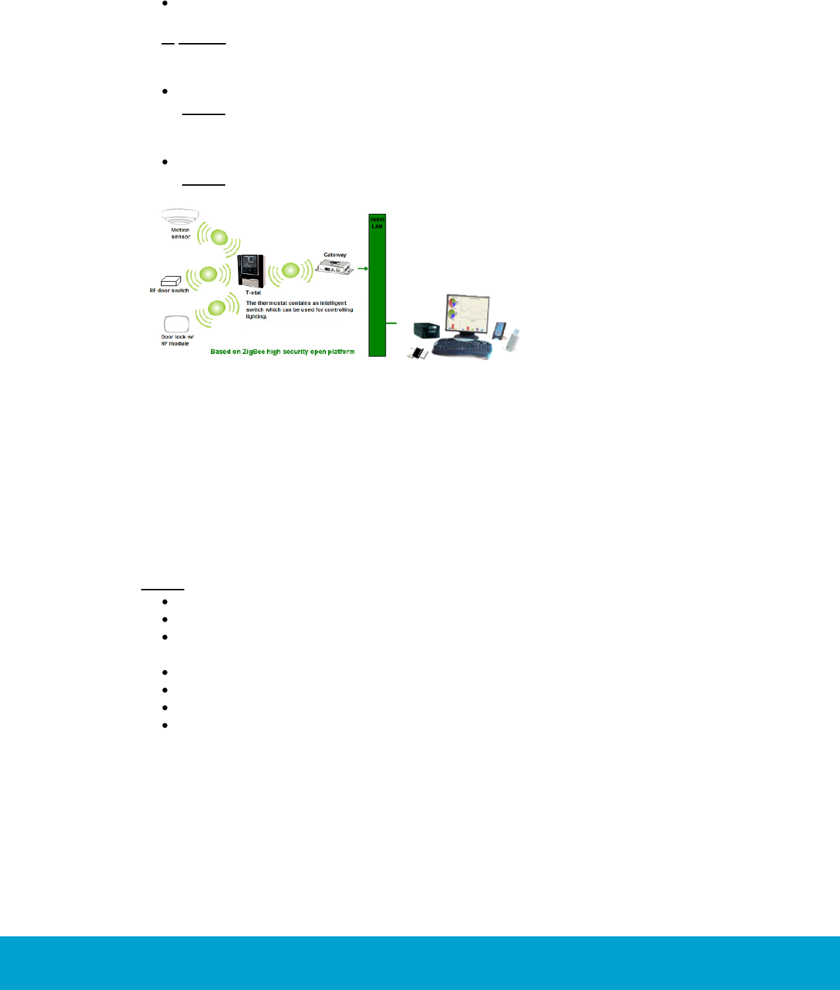
Figure 1: Orion EMS example configuration
The thermostat has a built-in ZigBee router via which it communicates to the software
and the devices within the room. The thermostat stores all parameters needed for Orion
EMS; if the thermostat controller is used as well, the parameters (with a few exceptions;
see Installation manual Orion High Voltage Thermostat for details) are instead stored in
the thermostat controller. The parameters are either transferred online from the software
or from the Orion Service software; see Quick reference guide Orion Service for more
information about the latter.
Note: For each room number, it is possible to have either
one wired thermostat
up to five motion sensors
up to five door switches
OR one thermostat controller
up to five battery thermostats
up to five motion sensors
up to five door switches
9
ASSA ABLOY Hospitality 66 8003 015-3
1.2 Terminology
Deadband
The range the temperature is allowed to drift before heating or
cooling is activated.
Default setpoint
Default setpoint is the temperature which the thermostat is set to
until a guest changes the temperature. The thermostat will also
return to the default setpoint after guest check-out.
Dynamic setback
The dynamic setback temperatures are configured as
a set number of degrees above or below the guest setting.
For example, if the guest setting is 68 ºF (20 ºC) and the
unoccupied setback is configured to 7 ºF (4 ºC) above the
guest setting, the system will allow the temperature to drift
to 75 ºF (24 ºC) when the room is unoccupied.
EMS
Energy Management System
Exterior door
timeout
The time that will pass before the HVAC is turned off after
an exterior door is left open.
FCU
Fan Coil Unit
Freeze guard
If the temperature in any room with a thermostat goes
below 39 ºF (4 ºC), there will be an alarm and the HVAC
will start heating.
HVAC
Heating Ventilation and Air Conditioning
Intelligent switch
The intelligent switch is an output for lighting control which works
according to the occupancy status. The available alternatives for
intelligent switch are:
disabled; default
use RV output
use G2 output
If intelligent switch is applicable, normally 'Use RV output' should
be marked unless the air handler is a heat pump. In the latter
case, mark 'Use G2 output' instead.
Motion sensor
A device that detects a person's movement in an area.
Occupied
Someone is physically in the room; see section Room occupied
for more information.
Occupied limits
Limits the Set temperature range, i.e. the temperature
which the guest can set the thermostat to.
PTAC
(Package Terminal
Air Conditioner)
A PTAC is a fully self contained system that is typically
located on the exterior wall of a hotel room. These units
come in standard control or heat pump models.
Pre-condition time
Note: This
parameter
requires that the
Online option has
been set in
Visionline.
Number of hours the thermostat shall run at the default
setpoint after check-in. If no entry has been done when
this time expires, the unoccupied setback will be assumed.
The pre- condition time can be 1-12 hours or 'disabled';
default is 2 hours.
10
ASSA ABLOY Hospitality 66 8003 015-3
Pulse length
The welcome scene can be set up to have a pulse length:
0 = welcome scene always off
chosen length in the interval 1-255 seconds
Refresh cycle
The Orion EMS system can, in setback control, run the A/C unit
every 25 minutes for a period of 2 minutes to re-circulate the
air in the room; the optional function is only for cooling mode.
Setback
The temperature the room is allowed to drift to when the room
is unoccupied. Also see dynamic setback and static setback.
Setback override
The Orion EMS features can be overridden until the room is
unsold again, or until a certain time. If desired, the time can
be set far ahead so that the setback override is in practice
until further notice.
Setpoint
The temperature which the guest has set on the thermostat.
Static setback
The static setback temperatures are configured in the system
and do not change based on the guest settings. For example,
if the unoccupied upper setback temperature is 79 ºF (26 ºC),
the system will allow the temperature to drift to 79 ºF (26 ºC)
when the room is unoccupied regardless of the thermostat
setting (this example assumes that it is summertime) when
the room becomes unoccupied. As soon as the guest returns
to the room, the temperature is returned to the guest setting.
Unoccupied
No one is physically in the room although the room
may be currently rented; see section Room unoccupied
for more information.
Unsold
The room is not currently rented and no one is in the room.
In this case, a deeper setback is implemented for greater
energy savings. See section Room unsold for more information.
Welcome scene
If desired, it is possible to have a welcome scene which it is
activated when the occupancy state for a room changes from
unsold to unoccupied. The available alternatives for welcome
scene are (default is 'disabled'):
disabled
use RV output
use G2 output
use solid state relay
Table 1

11
ASSA ABLOY Hospitality 66 8003 015-3
1.3 General about Orion Service
A service device and the Orion Service software are used for:
initializing thermostats (setting room number and loading configurable
parameters)
commissioning the thermostat and the motion sensor in the network so
the messages are routed correctly
retrieving and displaying the event log from the thermostat
upgrading module firmware in thermostat and motion sensor
performing diagnostic operations, e.g.
-simulating inputs - e.g. door switch, motion/temperature
-reading out status of thermostat (the status of the motion sensor is
also shown)
-showing the output to the HVAC
-making a functionality test including fast clock mode; the thermostat
will raise the time one minute per second to test e.g. the room not
occupied timer
See Quick reference guide Orion Service for more information about how the above
operations are performed.
1.4 General about alarms
All Orion EMS alarms are shown in the dialog Energy management summary; see
chapter 3 for more information. In addition, they are shown in the alarm list. Unless
Orion EMS is installed as a separate client, the alarm list will also show other types
of alarms not related to Orion EMS, e.g. housekeeping failed.
If the Communication option is set in the software, notifications about Orion EMS
alarms can be sent via e-mail or SMS and reports can be sent by e-mail. The reports
that can be sent concern e.g.
energy savings
preventative maintenance schedules
occupancy (the report shows the number of occupied rooms each night; a room is
regarded as occupied for the night if it is physically occupied and there is at least
four hours of occupancy between 8 PM and 6 AM)
occupancy trend (the report is combined with the energy savings report and
shows occupancy during each time of the day; it is also possible to make as
an average for a longer period)
battery warnings
events for a selected room
offline rooms
These reports are sent via e-mail at the selected period to users that have been set
up in the user notification list of the software to receive the reports; see Installation
instruction Communication option for further information.

12
ASSA ABLOY Hospitality 66 8003 015-3
1.5 Events and commands
To the guest, the thermostat appears and operates as a standard digital thermostat;
however, this device also receives entry and exit information from the door lock or
switch as well as motion detected information from the motion sensor. This information
is used to determine the occupancy status of the room and implement energy savings
strategy based on this information.
In order for the locks to send door events to the thermostats, EMI events must
be enabled. This is achieved by presenting an Enable EMI events card at each lock.
The card is one of the ZigBee configuration cards that can be issued in Visionline;
see Installation manual Orion High Voltage Thermostat for details. The following
events are sent to the thermostat from the motion sensor:
motion detected
battery status
If the lock is online, the following events are sent to the thermostat from the lock:
door open – staff card
door open – guest card; includes check-out date/time, suite rooms and
first time use
door open from inside
door closed
deadbolt thrown/released
The thermostat stores the 75 latest events in a log.
Note: In addition to the relevant events from the lock to the thermostat, additional
events are sent from the lock to
the hotel system.
There are also commands sent from the thermostat to the lock (if online) and the
motion sensor:
to the lock: the optional auto-DND, which functions as privacy; no staff cards
will be able to open the door (only guest cards and emergency cards will open)
to the motion sensor: to turn off the motion sensor when the room is occupied
and the door is closed, and to turn on the motion sensor again when the door
is opened
Note: The commands from the thermostat to lock and motion sensor are not logged
as events.
13
ASSA ABLOY Hospitality 66 8003 015-3
1.5.1 Thermostat event report
The thermostat event report shows all events that have been sent online from the
thermostats or been transferred to the server via Orion Service; see Quick reference
guide Orion Service for details. The housekeeping function keeps the list size limited
by removing events that are older than a user defined number of days; default is
7 days. To look at a thermostat event report:
1. Double click on Thermostat events under the Reports tab in the
navigation window.
2. Enter the applicable search filter(s) under the tabs Events, Door or Miscellaneous
(see more information below) before pressing the Enter key or clicking OK.
Note: At least one of the following requirements must be met:
- a room is selected
- one or two event sub groups are selected
3. It is also possible to reload a previous search filter: click the Load… button in
the Events - Search filter dialog, browse to the desired file, mark it and click
Open. If you want to save a search filter for future searches: click the Save…
button, browse to where you want to save the file, give it a name and click Save.
If the filter should be shown under Custom in the Reports tab, it must be saved
in any of the following locations:
- the folder ’Custom Reports’ in the software installation folder
- the public documents folder
- the documents folder
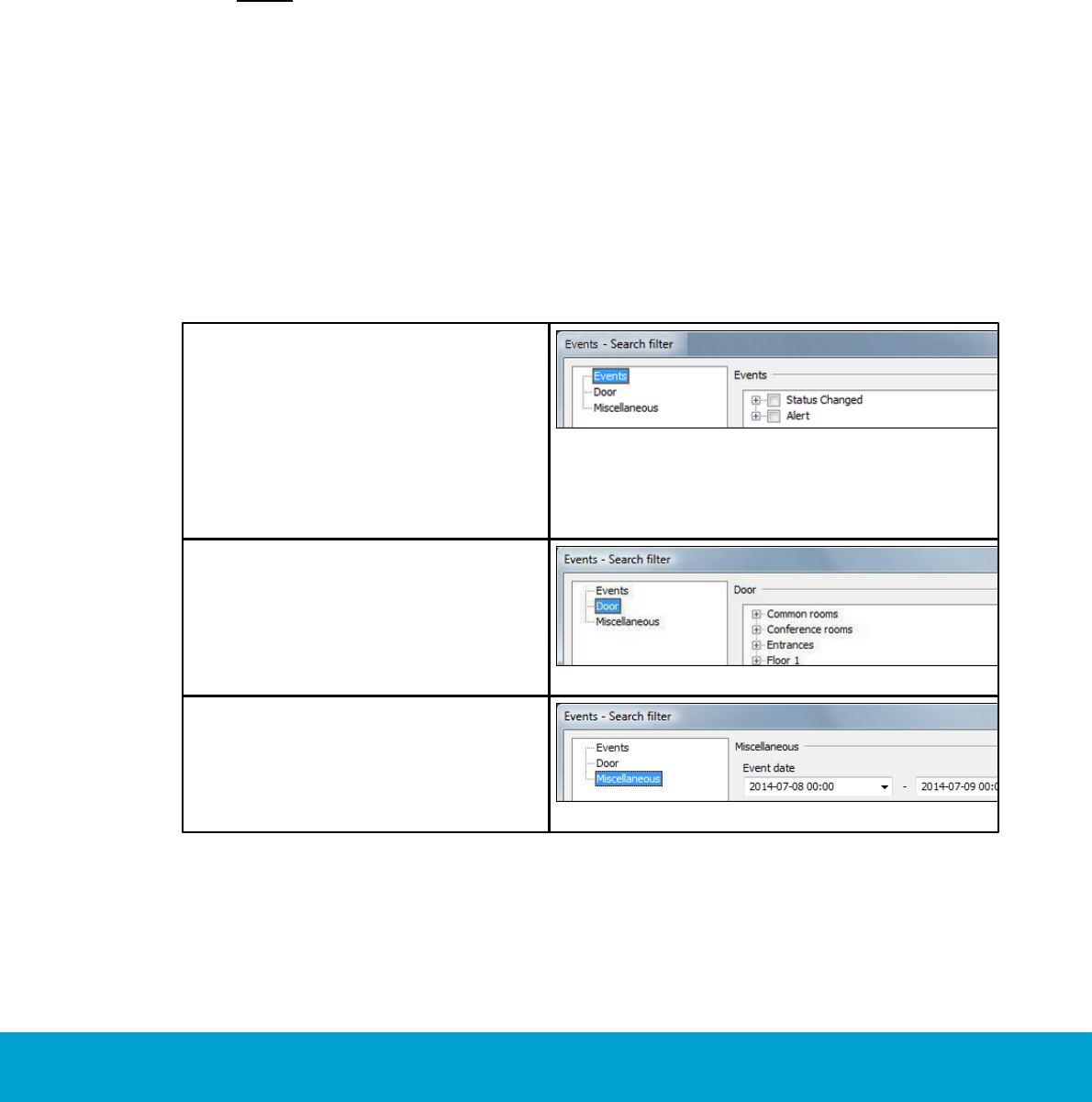
The search filters that can be applied on thermostat events are:
Events – with this filter you can pick
out a specific event, or certain types
of events. The main types are Status
Changed and Alert. Within each main
type, there are event sub groups
which can be divided further into
specific events. If needed, use the
Check all/Uncheck all buttons at
the bottom of the dialog.
Figure 2
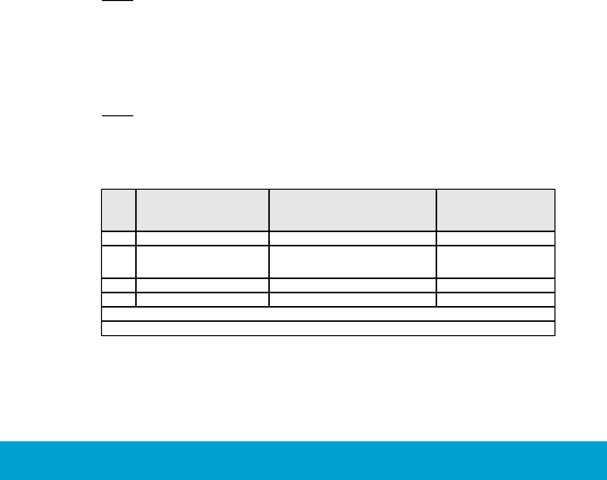
Door – with this filter you can pick
out events for a certain room. Click
the plus sign to expand a door area
and mark the applicable door.
Figure 3
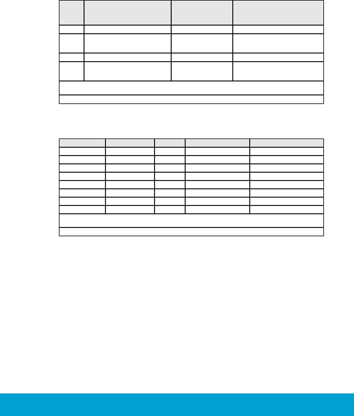
Miscellaneous – with this filter
you can pick out events from certain
event dates.
Figure 4

14
ASSA ABLOY Hospitality 66 8003 015-3
1.6 Basic EMS logic
The thermostat along with the motion sensor, lock and/or RF door switches, monitors
the occupancy state of the room and operates based on this information. When the
room is occupied, the guest is given control and can set the desired temperature.
The thermostat will then heat or cool the room as necessary to meet the guest setting.
When the room is not occupied, the thermostat will operate based on the configurable
parameters of the system. The three occupancy states are occupied, unoccupied
and unsold. The following events are considered as in-room events:
motion
deadbolt engaged
thermostat key pressed
1.6.1 Room occupied
When the room is occupied, control of the HVAC system is given to the guest.
The guest sets the desired temperature and the HVAC system will control the room
based on this setting. The Orion thermostat will enter the occupied state only when
the door is closed and in-room events are detected (motion, deadbolt engaged,
thermostat key pressed). At this point, the guest has full control of the room
temperature.
Note: 'Occupied limits' may be used to restrict the guest setting limits.
1.6.2 Room unoccupied
When the room is not occupied, the energy management logic takes control of the
room based on the configurable parameters of the system. The system will set back
the temperature to the unoccupied setting. The system has both an upper setback and
a lower setback. The unoccupied setbacks may be static or dynamic; for unsold rooms,
only a static setback is used. See section Terminology for more information about static
and dynamic setback.
The thermostat will enter the unoccupied state upon the door opening or closing. If no
in-room event such as motion is detected, the thermostat will remain in the unoccupied
mode. The thermostat will continue to operate at the guest setting for the duration of
the configurable 'Room not occupied' timer, at which point it maintains the room
temperature based on the unoccupied setback temperatures.

15
ASSA ABLOY Hospitality 66 8003 015-3
1.6.2.1 Door open in 'room unoccupied' mode
If the door is left open, the occupancy state will remain as unoccupied regardless of
whether or not motion or another in-room event is detected. There is however also
a run state in the thermostat which is based on the set-point/guest setting. The run
state works differently depending on whether the open door is interior or exterior,
see details below.
If the open door is configured as an interior door (i.e., opens to another air conditioned
space), the thermostat will operate based on the guest setting as long as motion
or another in-room event is detected. Each time an in-room event is detected, the
‘Room not occupied’ timer will restart. If the ‘Room not occupied’ timer elapses without
motion or another in-room event being detected, the thermostat will maintain the room
temperature based on the unoccupied setback temperatures.
If the open door is an exterior door (i.e., opens to a non-climate controlled space),
the thermostat will turn off after the ‘Room not occupied’ timer expires regardless
of whether or not motion is detected.
Note: If the exterior door timeout is set to ‘Short’, the thermostat will turn off the
air handler after 20 seconds. See chapter 4 Thermostat profiles list, section Under
the Timeout tab, for details about setting the exterior door timeout.
1.6.3 Room unsold
To achieve more energy savings when the room is not rented, the setback is deeper
than when the room is rented but unoccupied. The system will enter the unsold setting
when the room has been unoccupied for the duration of the configurable ’Room not
sold’ timer. In the unsold mode, the temperature is based on the unsold setback
temperatures.
Note: If using an online system, the room will immediately enter the unsold mode upon
receiving a check-out command from the property management system (PMS) or at
guest card expiration.
Note: The unsold mode gives the greatest potential for energy savings. For this reason,
the online system allows for maximum energy savings as the room does not need to
wait until the ‘Room not sold’ timer elapses to enter the deep setback mode.
1.6.3.1 Door open in 'room unsold' mode
Similar to the door open condition in the unoccupied state, the thermostat will control
the temperature based on the guest setting when an interior door is open and motion
(or any other in-room event) is detected for a period of time equal to the ‘Room not
occupied’ timer. If the timer elapses with no further detection of in-room events,
the thermostat will revert to maintaining the room temperature at the unsold setback.
If an exterior door is left open, the thermostat will turn the air handler off.
16
ASSA ABLOY Hospitality 66 8003 015-3
1.6.4 Staff entry
In order to maximize energy savings, certain considerations must be taken into
account when staff members enter the room.
1.6.4.1 Door monitored by RF door switch
If the position of the door is monitored by an RF door switch, the staff member
must leave the door open to avoid interrupting the ‘Room not sold’ timer. If the staff
member allows the door to close, the room will enter the occupied state upon motion
detection. As long as the door is left open, the ‘Room not sold’ timer will not be reset.
1.6.4.2 Door monitored by electronic lock
If the door position is monitored by the electronic lock and a staff key unlocks the door,
the room will not enter the occupied state even if motion is detected while the door is
closed. However, if a thermostat key is pressed or the deadbolt is engaged while the
door is closed, the room will enter the occupied state.
Note: If a staff member lets a guest into a room with the door position monitored by
an electronic lock, the room will remain unoccupied until the deadbolt is engaged or a
button on the thermostat is pressed.
1.6.5 Operating states
The following series of tables shows the operation of the system in various scenarios.
Note: The scenarios consider that the unoccupied (or exterior door open) timers have
expired if applicable.
1.6.5.1 One interior door
Door
In-room Event
(Motion/
Thermostat Key Pressed/
Deadbolt Engaged)
HVAC
State
Closed
Yes
Per guest setting
Occupied
Open
Yes
Per guest setting if opened by guest.
Setback if opened by staff.
If no lock interface, per guest setting.
Unoccupied or Unsold
Closed
No
Setback
Unoccupied or Unsold
Open
No
Setback
Unoccupied or Unsold
Table 2
17
ASSA ABLOY Hospitality 66 8003 015-3
1.6.5.2 One exterior door
Door
In-room Event
(Motion/
Thermostat Key Pressed/
Deadbolt Engaged)
HVAC
State
Closed
Yes
Per guest setting
Occupied
Open
Yes
OFF (20 seconds or
standard unoccupied
time)
Unoccupied or Unsold
Closed
No
Setback
Unoccupied or Unsold
Open
No
OFF (20 seconds or
standard unoccupied
time)
Unoccupied or Unsold
Table 3
1.6.5.3 One exterior and one interior door
Interior Door
Exterior Door
Motion
HVAC
State
Closed
Closed
Yes
Per guest setting
Occupied
Open
Closed
Yes
Per guest setting
Unoccupied or Unsold
Closed
Open
Yes
OFF
Unoccupied or unsold
Open
Open
Yes
OFF
Unoccupied or Unsold
Closed
Closed
No
Setback
Unoccupied or Unsold
Open
Closed
No
Setback
Unoccupied or Unsold
Closed
Open
No
OFF
Unoccupied or Unsold
Open
Open
No
OFF
Unoccupied or Unsold
Table 4
18
ASSA ABLOY Hospitality 66 8003 015-3
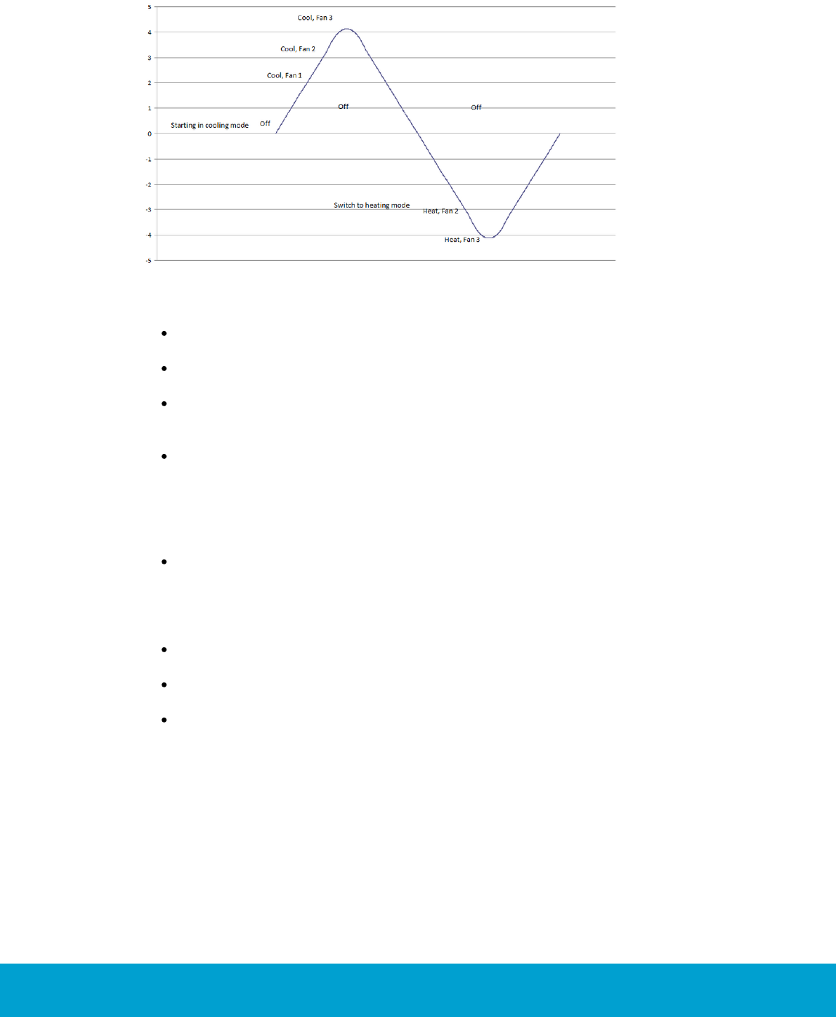
1.6.6 Thermostat control chart
Figure 5
The thermostat control can be illustrated in a control chart, see example above.
If the temperature drifts above the setpoint or setback (depending on occupancy
mode), the HVAC starts in cooling mode.
The thermostat deadband is in this case 2 ºF, so when the temperature is within
2 ºF from the setpoint the HVAC is off (from 0 to 2 in the picture).
If the temperature continues to rise, the thermostat output for ‘Fan 1/Low’
is triggered, then the output for ‘Fan 2/Medium’ and finally the output for
‘Fan 3/High’.
If the temperature starts dropping, the HVAC then switches to heating mode.
There is however a heat/cool switch deadband which in this example is 3 ºF,
so the temperature is allowed to drift 3 ºF from the setpoint before the HVAC
switches from cooling mode to heating mode. From 0 to -3 in the picture the
HVAC is off; the output for ‘Fan 1/Low’ is therefore not triggered, since this
would have been at -2.
If the temperature continues to drop, first the output for ‘Fan 2/Medium’ is
triggered and then the output for ‘Fan 3/High’.
The Orion EMS devices strive towards different temperatures depending on if the
room is occupied, unoccupied or unsold.
For ‘occupied mode’ the goal is the setpoint, i.e. the temperature which the
guest has set on the thermostat.
For ‘unoccupied mode’ the temperature drifts to the unoccupied setback,
which can be static or dynamic.
For ‘unsold mode’ the temperature drifts to the unsold setback.

19
ASSA ABLOY Hospitality 66 8003 015-3
1.7 Orion EMS parameters
There are a number of Orion EMS parameters whose values can be modified in the
software. Different operator templates can be given different authorities to modify
the parameters. Some parameters are considered as basic and some as advanced.
Note: In the parameter column below, it is also stated in what software dialog the
parameter is found.
Note: The parameter dwell-off time is a setting that will guard against short-cycling
and its value is 5 minutes. The parameter is not visible in the software and cannot be
changed, not even by the distributor. Default is that the dwell-off time is off; it is only
applicable when 'heat pump' is chosen as HVAC type. In the 'heat pump' case, the
thermostat will automatically force the dwell-off time to be on.
Parameter
Description
Available choices
Default setting
Default set point
(Thermostat profile
details dialog, Misc tab)
The temperature which the
thermostat is set to until a guest
changes it. The thermostat will
also return to the Default set point
after check-out.
64-75 ºF
70 ºF
Enable lights during
pre-condition time
(Thermostat profile
details dialog, Misc tab)
Note: This parameter
requires that the Online
option has been set in
Visionline.
The lights are enabled according to
the chosen intelligent switch setting
during the pre-condition time.
Disabled
Enabled
Enabled
Exterior door timeout
(Thermostat profile
details dialog,
Timeout tab)
If the exterior door is open and the
default 'Normal' is used, the HVAC
will - regardless of room occupancy
status - turn off after the number
of minutes entered at 'Room not
occupied'. Default is 8 minutes; see
Room not occupied timer in Table 6.
If the exterior door is open and
'Short' is used, the HVAC will turn
off after 20 seconds.
Normal/short
Normal
Exterior input behaves
as window
(Thermostat profile
details dialog, Misc tab)
The HVAC will be shut off after a
configured time (short or normal),
but the thermostat does not change
the occupancy status. The exterior
door timeout is triggered by the
wired input for exterior door open
(EX1) on the thermostat.
Disabled
Enabled
Disabled
Fan control
(Thermostat profile
details dialog, Fan tab)
The thermostat has a button which
allows the user to select from up
to three fan speeds, or to choose
‘Automatic’ (AUTO) if the thermostat
Auto/manual
Max fan cool
(low, mid, high)
Manual
High
High

20
ASSA ABLOY Hospitality 66 8003 015-3
should determine the appropriate
fan setting.
Note: The ability to control fan
speeds depends on the capability
of the air handler, as some systems
do not have three fan speeds.
Max fan heat
(low, mid, high)
Fan on when satisfied
(Thermostat profile
details dialog, Fan tab)
When enabled, the low fan speed
will continue to run even when the
setpoint has been reached. This
only applies to an occupied room.
Disabled
Enabled
Disabled
Freeze guard
(Thermostat profile
details dialog, Misc tab)
There will be an alarm and the
HVAC will start heating if the
temperature in any room with
thermostat goes below 39 ºF (4 ºC).
Disabled
Enabled
Enabled
Heat/cool switch
deadband
(Thermostat profile
details dialog,
Deadband tab)
This parameter is only applicable
if auto switching mode has been
chosen under the HVAC tab in the
Thermostat profile details dialog.
The heat/cool switch deadband is
the range the temperature is allowed
to drift before switching from heat to
cool or cool to heat.
2-4 ºF
3 ºF
Humidity control
(Thermostat profile
details dialog, Misc tab)
When the humidity control option
is checked, the thermostat will
implement control measures if the
humidity in the room gets too high.
Note: The control measures will
only be implemented when the
room is unoccupied or unsold.
Disabled
Enabled
Disabled
HVAC control
(Thermostat profile
details dialog, HVAC tab)
See available choices to the right.
'Heat pump reversed valve (Type B)'
means that the reversing valve
output is on when heating.
'Heat pump reversed valve (Type O)'
means that the reversing valve
output is off when heating.
For 'HVAC heating'
and 'HVAC cooling':
n/a
4-pipe fan coil
2-pipe fan coil
2-pipe fan coil with
automatic switching
Proportional
Floating valve
For 'HVAC heating' only:
Heat pump reversed
valve (Type B)
For 'HVAC cooling' only:
Heat pump reversed
valve (Type O)
n/a
Intelligent switch
(Thermostat profile
details dialog, Misc tab)
The intelligent switch is an output
for lighting control which works
according to the occupancy status.
The intelligent switch is an output
for lighting control which works
according to the occupancy status.
Disabled
Use RV output
Use G2 output
Disabled

21
ASSA ABLOY Hospitality 66 8003 015-3
Maintenance intervals
(Tools/Options dialog,
expand Energy
management and
choose Maintenance)
Number of hours before the three
different maintenance alarms
should be triggered.
- Maintenance counter 1 is for
fan time/total HVAC time
- Maintenance counter 2 is
for 'cooling'
- Maintenance counter 3 is for
'cooling or heating'
Names for the three
maintenance alarms.
Maintenance 1:
0-65535 hours
Maintenance 2:
0-65535 hours
Maintenance 3:
0-65535 hours
Maintenance 1:
0 hours
Maintenance 2:
0 hours
Maintenance 3:
0 hours
Max HVAC runtime
(Tools/Options dialog,
expand Energy
management
and choose General)
An alarm is triggered if a HVAC runs
this long without turning off.
30-300 minutes
120 minutes
Max setback override
(Tools/Options dialog,
expand Energy
management
and choose General)
The Orion EMS features may be
overridden when needed, e.g. for
VIP guests where no setbacks
should apply; click here for details.
If a number of hours is entered at
'Max setback override', an alarm will
be triggered if the setback override
exceeds this number of hours. If the
default 0 hours is used, no alarm
will be triggered.
0-99 hours
0 hours
Occupied limits
(Thermostat profile
details dialog, Limits tab)
With this parameter, it is possible
to limit the allowed temperature
range when the room is occupied.
If this is the case, mark the
checkbox 'Use occupied limits' and
enter the values for upper limit and
lower limit.
On/off
Upper limit
(75-90 ºF)
Lower limit
(62-72 ºF)
Off
84 ºF
68 ºF
On exterior open,
keep lights on
(Thermostat profile
details dialog, Misc tab)
The lights will be left on if the
exterior door timeout has been
triggered by
- the wired input for exterior door
open on the thermostat
OR
- a non-wired door switch configured
as exterior
Disabled
Enabled
Disabled
Pre-condition time
(Thermostat profile
details dialog, Misc tab)
Note: This parameter
requires that the Online
option has been set in
Visionline.
Number of hours the thermostat
shall run at the default setpoint
after check-in. If no entry has
been done when this time expires,
the unoccupied setback will
be assumed.
Disabled
1-12 hours
2 hours
Pulse length
(Thermostat profile
details dialog, Misc tab)
The welcome scene can be set up
to have a pulse length.
0 = welcome scene
always off
chosen length
in the interval
1-255 seconds
0 seconds
22
ASSA ABLOY Hospitality 66 8003 015-3
Refresh cycle
(Thermostat profile
details dialog, Misc tab)
The Orion EMS system can in
setback control run the A/C unit
every 25 minutes for a period of
2 minutes to re-circulate the air
in the room; this optional function
is only for cooling mode.
Enable/disable
Disable
Room not occupied
timer
(Thermostat profile
details dialog,
Timeout tab)
This is the amount of time the
thermostat maintains the guest
setting after the room has entered
the unoccupied state.
1-120 minutes
8 minutes
Room not sold timer
(Thermostat profile
details dialog,
Timeout tab)
When the room has been
unoccupied for this number
of hours, it will enter unsold mode.
12-24 hours
16 hours
Set door state
to closed when
ajar alarm received
(Thermostat profile
details dialog, Misc tab)
If the checkbox Set door state
to closed when door ajar alarm
received is marked, the door state
is set to closed once the door
ajar timeout has been triggered.
This allows the thermostat to go
to occupied state even if the door
is not physically closed.
Note: This checkbox is applicable
if you have a malfunctioning
door switch.
Disabled
Enabled
Disabled
Temperature display
(Thermostat profile
details dialog, Misc tab)
The thermostat will show either
the room temperature or the
temperature that has been set
by the guest.
Room temperature/
set temperature
Room
temperature
Thermostat deadband
(Thermostat profile
details dialog,
Deadband tab)
The range the temperature is
allowed to drift from the setpoint
before the heat or air conditioner
is turned on
1-3 ºF
2 ºF
Unoccupied setbacks
(Thermostat profile
details dialog, Limits tab)
The applicable number of degrees
as upper limit and lower limit for
setback if a room is unoccupied.
Static/dynamic
Static upper
(72-90 ºF)
Static lower
(55-70 ºF)
Dynamic upper
(2-8 ºF offset)
Dynamic lower
(2-8 ºF offset)
Static:
78 ºF
68 ºF
Dynamic:
4 ºF
4 ºF
Unsold setback
(Thermostat profile
details dialog, Limits tab)
The applicable number of degrees
as upper limit and lower limit for
setback if a room is unsold.
Summer
(74-90 ºF)
Winter
(55-70 ºF)
84 ºF
64 ºF
Welcome scene
(Thermostat profile
details dialog, Misc tab)
If desired, it is possible to have a
welcome scene which it is activated
when the occupancy state for a
room changes from unsold to
unoccupied.
Disabled
Use RV output
Use G2 output
Use solid state
relay
Disabled
Table 5
23
ASSA ABLOY Hospitality 66 8003 015-3
1.8 Operator templates
The operator templates decide the level of authority for different Orion EMS
operations. To change the authority for handling thermostat parameters:
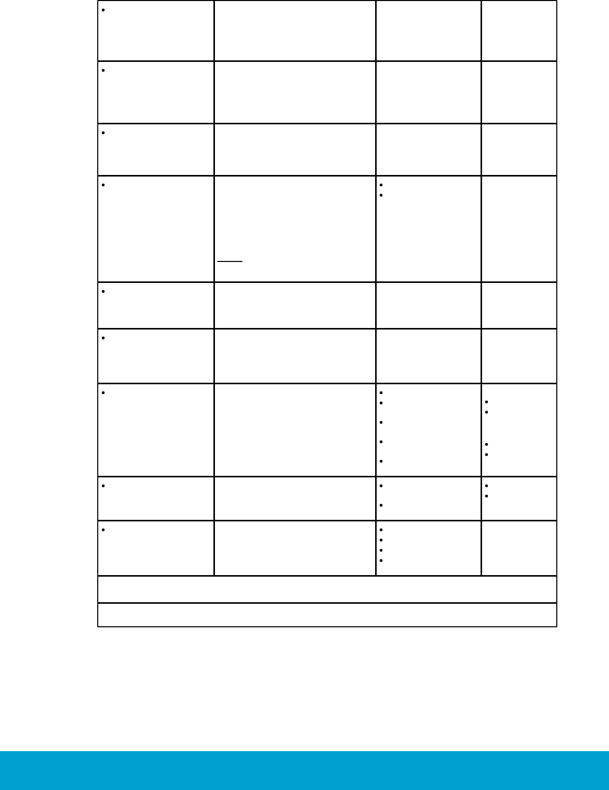
1. Double click on Operator
templates under the Lists
tab in the navigation window.
2. In the Operator templates
dialog, mark the applicable
operator template and click
Properties; or click Add
if a new operator template
should be added.
Figure 6
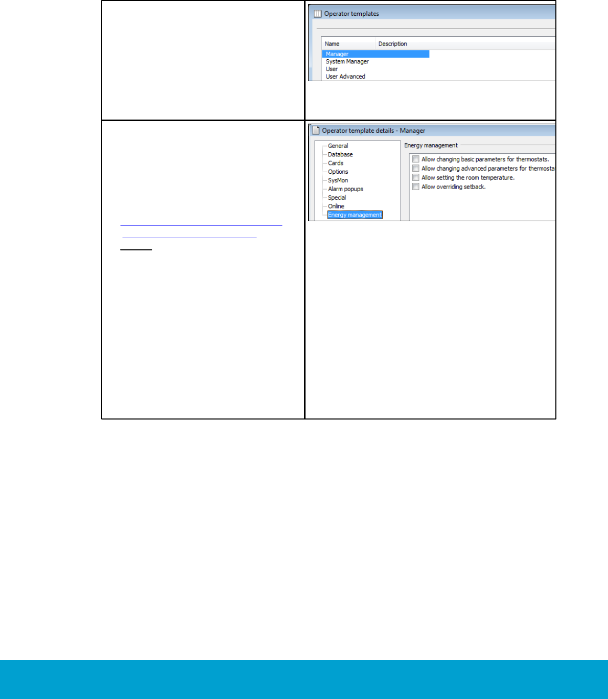
3. In the Operator template details
dialog, choose the tab Energy
management in the left part
of the dialog. Make the desired
changes regarding
- changing basic parameters
- changing advanced parameters
- setting the room temperature
- overriding setback mode
Note: By default, all four items
above are marked for system
manager but unmarked for
other operator templates.
4. If a new operator template was
added, go through the other tabs
in the left part of the Operator
template details dialog and fill
in the applicable information;
see Setup manual Visionline
for detailed information.
5. Click Update (or Save if a new
operator template was added)
and Close.
Figure 7
24
ASSA ABLOY Hospitality 66 8003 015-3
1.8.1 Operator template X-reference
At Tools/Operator template X-reference, it is possible to change the operator
template authorities for thermostat events, thermostats, thermostat profiles and
EMS summary. By default, all default operators (manager, system manager, user and
user advanced) can view the concerned dialogs. System manager can by default also
add, update and remove thermostats and thermostat profiles. To change the authority
for system manager, a distributor must be logged on. New operator templates (e.g.
Test Template in the example screenshots below) will by default neither be able to
view the concerned dialogs, nor add, update or remove items in the dialogs where this
is applicable. To modify the authorities:
1. Go to Tools/Operator template X-reference.
Figure 8
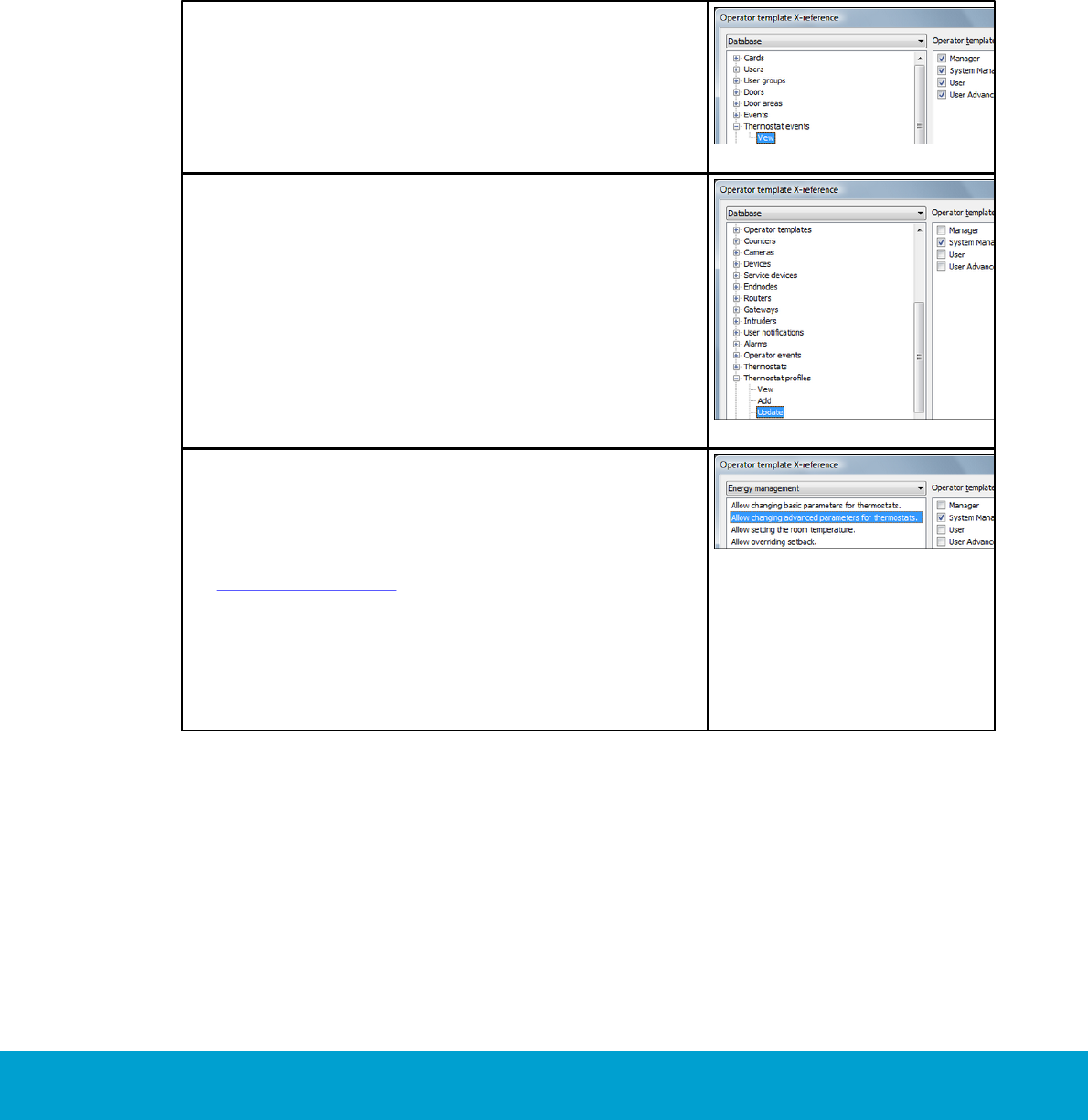
2. Under the Database alternative in the drop-down-
menu, click the plus sign in front of the concerned
item. For the items Thermostat events and EMS
summary, the only available alternative is View
(see Figure 8). For the items Thermostats and
Thermostat profiles, the alternatives View, Add,
Update and Remove are available; see examples
in the screenshots to the right. Mark the applicable
alternative to the left and unmark/mark the
concerned operator template(s) in the right
part of the dialog.
Figure 9
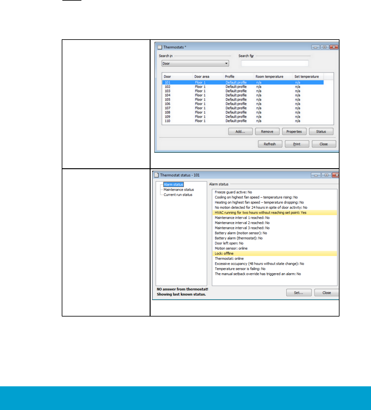
3. Under the Energy management alternative in the
drop-down-menu, mark the applicable choice in the
left part of the dialog. The checkboxes to the right
will reflect anything that has been saved in the
Operator template details dialog; see section
Operator templates for details. In the right part
of the dialog, mark/unmark the applicable
operator template(s).
4. If applicable, repeat step 3 with other alternatives
in the left part of the dialog.
5. When all applicable changes according to steps 2-4
above have been performed, click OK.
Figure 10
25
ASSA ABLOY Hospitality 66 8003 015-3
1.9 Setback override
The Orion EMS features may be overridden when needed, e.g. for VIP guests where
no setbacks should apply. Setback override may be enabled until the room is unsold or
until a certain time; if desired, until further notice.
Note: Override mode can also be set from Orion Service; see Quick reference guide
Orion Service for details. If the override mode has been set from Orion Service, it must
also be cleared from Orion Service. If the override mode has been set from the Change
thermostat settings dialog as below in this section, it can however be cleared either
from Orion Service or from the Change thermostat settings dialog.
1. Double click on
Thermostats under
the Lists tab in the
navigation window.
2. Mark the applicable
thermostat and click
Status.
Figure 11
3. In the Thermostat
status dialog, click
the Set button.
Figure 12
26
ASSA ABLOY Hospitality 66 8003 015-3
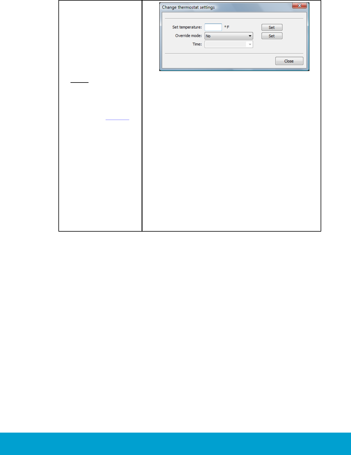
4. In the Change
thermostat settings
dialog, change the
Override mode to
the applicable one of
‘Manual (until unsold)’
or ‘Manual (until
time)’. If the latter is
chosen, enter the
applicable Time.
Note: If ‘Manual (until
time)’ is chosen, the
time is limited by the
parameter ‘Max
setback override’;
see section General for
details. If ‘Max setback
override’ is 0 (default),
there is however no
limitation in time and
the Orion EMS features
can be overridden until
further notice.
5. Click the Set button
next to the Override
mode drop-down
menu. The information
will be transferred
online to the
thermostat.
6. Click Close.
Figure 13
To set the room temperature:
1. Enter the desired temperature at Set temperature in the Change thermostat
settings dialog, and click the Set button next to that field. The information will
be transferred online to the thermostat.
27
ASSA ABLOY Hospitality 66 8003 015-3
2. Thermostat buttons and display
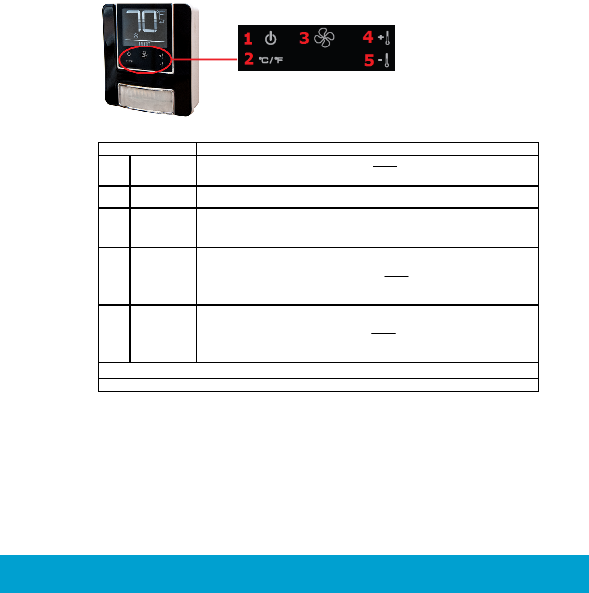
2.1 Thermostat buttons
The hotel guest controls the thermostat using the five buttons shown on the right side of the unit in
Figure 14.
Figure 14
Button
Description
1
On/Off
Toggles the thermostat power on and off. Note: Even when the unit is turned
off, the energy management logic will take over when the room is unoccupied,
to manage the temperature accordingly.
2
°C/°F
Controls the temperature display. Pressing this button will toggle the
temperature display between Celsius and Fahrenheit.
3
Fan control
Allows the user to select from up to three fan speeds or choose 'Automatic'
to let the thermostat determine the applicable fan setting. Note: The ability
to control fan speeds depends on the capability of the air handler as some
systems do not have three fan speeds.
4
Increase
temperature
Used for increasing the temperature which is set on the thermostat.
The thermostat will automatically choose between heat and cool, so there is
no need for the guest to select the function. Note: Some systems are unable to
switch between the heating and cooling functions. This does not change the way
the guest uses the system, but the thermostat is programmed accordingly and
will not call for a function that is not available.
5
Decrease
temperature
Used for decreasing the temperature which is set on the thermostat. The
thermostat will automatically choose between heat and cool, so there is no
need for the guest to select the function. Note: Some systems are unable
to switch between the heating and cooling functions. This does not change
the way the guest uses the system, but the thermostat is programmed
accordingly and will not call for a function that is not available.
Table 6
28
ASSA ABLOY Hospitality 66 8003 015-3
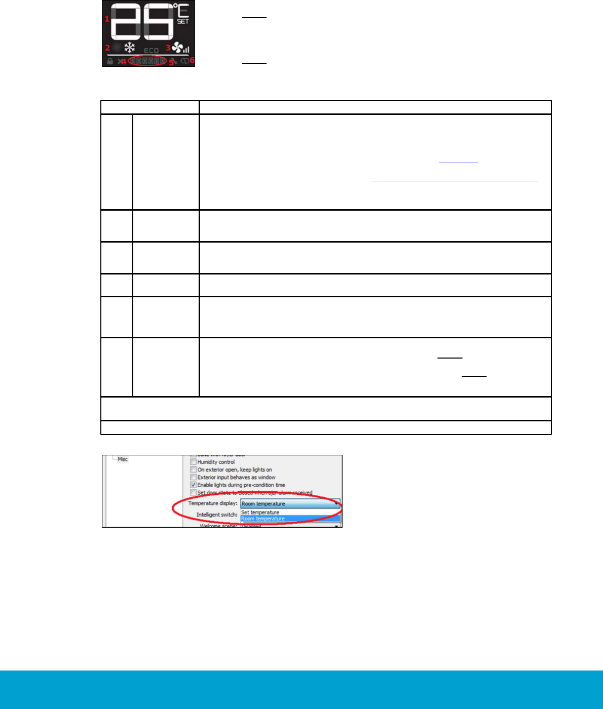
2.2 Thermostat display
The thermostat displays settings and operation details to the guest, e.g. room temperature and heat/
cool indications.
Figure 15
Note: After some seconds of inactivity of the thermostat buttons,
the display will shut down. The first key press of any button will activate
the display again, and then the buttons work as normal until the next
inactivity timeout occurs.
Note: Some of the indicators are not yet implemented in the thermostat
firmware and therefore not described in the below table.
Display indicator
Description
1
Temperature
The temperature display area shows the actual room temperature or the setpoint
temperature as well as the indication of Fahrenheit or Celsius. What to display is
configured when setting up the thermostat profile for the concerned thermostat;
choose 'Set temperature' or 'Room temperature' under the Misc alternative in
the Thermostat profile details dialog of Visionline, see Figure 16. If 'Room
temperature' is chosen, the thermostat will still display the set temperature for
a few seconds when the guest uses the Increase/Decrease temperature buttons.
The thermostat will then revert to show the room temperature again. When the
displayed temperature is the guest setting and not the actual room temperature,
the SET indicator is also displayed.
2
Heat/Cool
The thermostat displays universal icons for heating and cooling. The snow star
is the symbol to indicate the unit is in cooling mode and the sun is the symbol
to indicate heating mode.
3
Fan
The Fan indicator shows the fan speed of the unit. As the fan speed increases,
additional segments or the indicator are displayed. When in AUTO fan mode,
the word AUTO will appear at the Miscellaneous indicator, see below.
4
Miscellaneous
The Miscellaneous indicator is a multi-purpose indicator; it e.g. displays
the word AUTO when the automatic fan mode is enabled.
5
Wrench
The Wrench indicator is displayed when maintenance is required on any of the
Orion EMS devices in the room or on the HVAC unit. This icon is only displayed
to hotel staff. To get the details of the maintenance needed, connect the service
cable to the thermostat and choose the Status alternative in Orion Service.
6
Battery
The Battery indicator is displayed to hotel staff when the batteries are low
(on battery powered units) and in need of replacement. Note: This is a low
indicator only, not a segmented icon that displays the battery level. As soon as
this indicator is displayed, the batteries need to be replaced. Note: If the lock is
not used to monitor the door status, the service indicators will only be displayed
when the service cable is connected to the thermostat and Orion Service is used.
Table 7
Figure 16
29
ASSA ABLOY Hospitality 66 8003 015-3
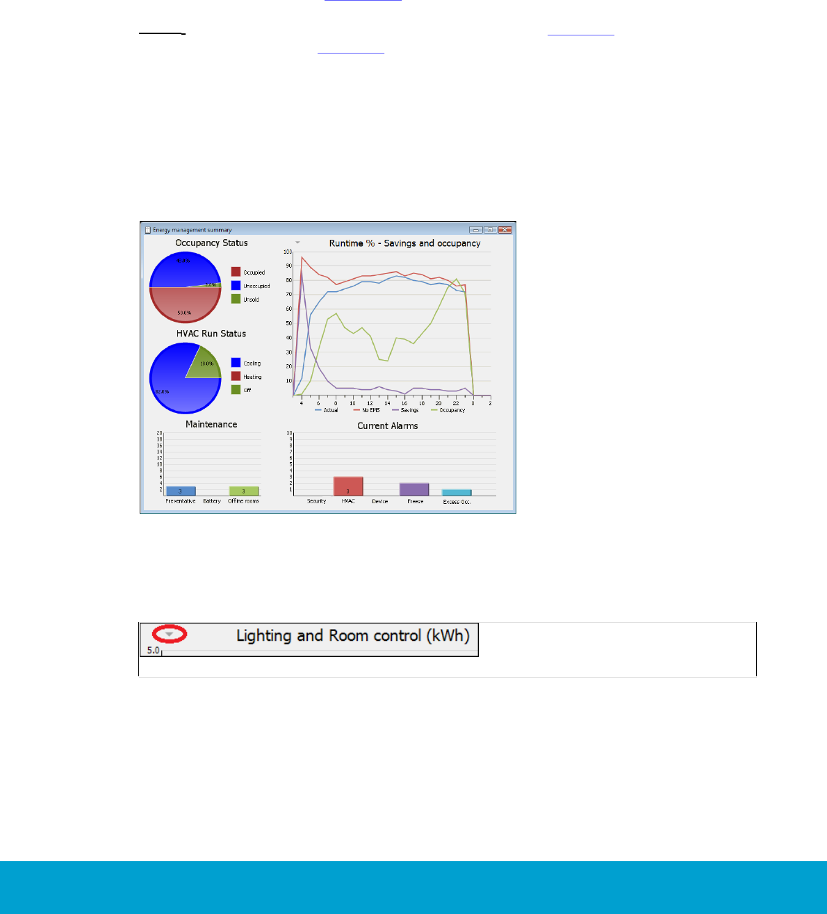
3. Energy management summary and alarm list
An EMS overview is shown in the dialog Energy management summary. The dialog
shows Occupancy Status and HVAC Run Status in circle diagrams, and Runtime %,
Maintenance and Current Alarms in xy diagrams. The current alarms are also shown
in the Alarms dialog, see section 3.2.
Note: It is also possible to get reports for occupancy (see chapter 6 for details) and
for energy statistics (see chapter 7 for details).
3.1 Energy management summary
1. Double click on EMS summary in the Lists navigation window. A dialog as in
the example below is shown.
Figure 17
By clicking the arrow to the left of the heading ’Runtime % - Savings and occupancy’,
it is possible to choose that the diagram should instead show ‘Lighting and Room
control (kWh)’.
Figure 18

30
ASSA ABLOY Hospitality 66 8003 015-3
Note: By clicking on any of the pie charts Occupancy Status or HVAC Run Status,
the corresponding Real time room status dialog will be shown. By clicking on any of
the bars in the Maintenance or Current Alarms bar chart, more information about
the alarms will be shown.
The Occupancy Status diagram shows how large share of the total number of
guest rooms that are:
occupied
unoccupied
unsold
See section Basic EMS logic for more information about the different states above.
The HVAC Run Status diagram shows how large share of the HVAC systems that are:
cooling
heating
off
The Runtime % diagram shows:
actual energy consumption in runtime
energy consumption if no EMS had been used
savings in energy consumption when EMS is used; Actual curve minus
no EMS curve
occupancy
The Maintenance diagram shows the number of:
preventative maintenance schedules; maintenance intervals 1-3
battery alarms from motion sensor
offline rooms (motion sensor/lock offline; thermostat offline)
The Current Alarms diagram shows the number of alarms related to:
security; door left open
HVAC
- thermostat cooling on highest fan speed – temperature rising
- thermostat heating on highest fan speed – temperature dropping
- HVAC running longer than maximum runtime (default 120 minutes)
without reaching setpoint
- too long duration of setback override
device; no motion detected for 24 hours in spite of door activity
freeze; the temperature in a room goes below 39 ºF = 4 ºC
excessive occupancy; if a room has had occupancy without door movement
for 48 hours
Note: When any of the alarms for maintenance 1-3 has been taken care
of, the concerned maintenance counter must be reset from Orion Service;
see section about configuring thermostat in Quick reference guide Orion Service.

31
ASSA ABLOY Hospitality 66 8003 015-3
3.2 Alarm list
The bar charts Maintenance and Current Alarms which are shown in the Energy
management summary dialog are also shown in the Alarms dialog. The dialog
contains two modes:
‘Runtime’ with callback data
‘Filtered’ with historical data
When an alarm is triggered, it first appears in a popup window down to the right
on the screen. See User manual Visionline for details about the different modes,
e.g. more about alarm popups for the runtime mode and what filters that can be
applied in the ‘Filtered’ mode.
To open the Alarms dialog:
1. Double click on Alarms under the Lists tab in the navigation window.
By default, the ‘Runtime’ mode of the Alarms dialog will be shown. By clicking on
any of the alarm bars ‘Preventative’ etc in the bar chart, all non-completed alarms
in the clicked alarm category will be shown in the alarm list.
Note: The Alarms dialog will also show alarms that are not related to Orion EMS;
except for in the separate Orion EMS client, where only Orion EMS alarms are shown.
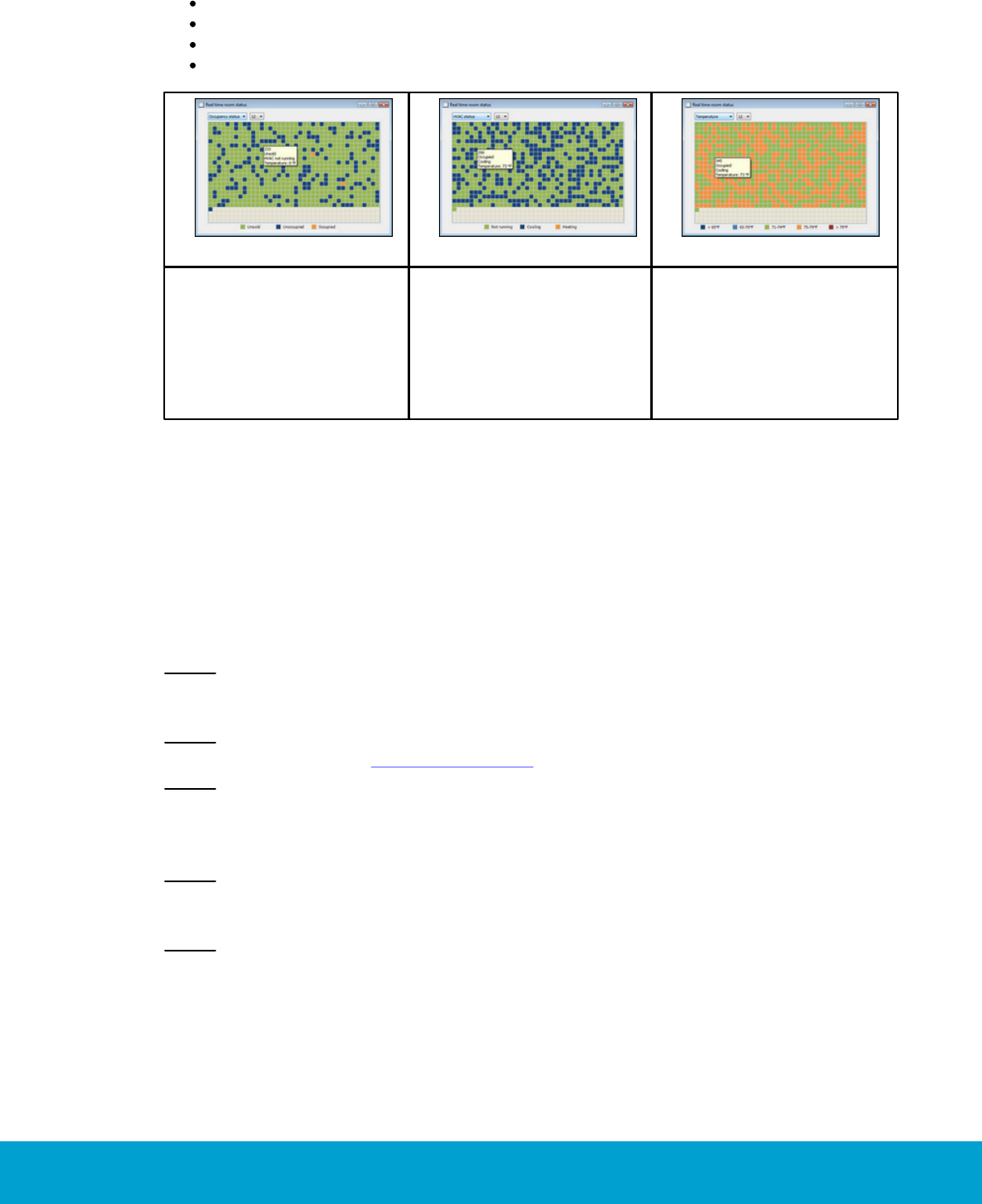
4. Real time room status
The dialog Real time room status shows occupancy status, HVAC status and
temperature for Orion EMS rooms in real time.
Note: It is also possible to get reports for occupancy (see chapter 6 for details) and for
energy statistics (see chapter 7 for details).
To open the Real time room status dialog:
1. Double click on Room status in the Lists navigation window (or click on any of
the circle diagrams in the EMS summary dialog, which is found by double clicking
on EMS summary under the Lists tab).
2. The size of the squares can be changed in the combobox to the right;
default is 12 pixels.
32
ASSA ABLOY Hospitality 66 8003 015-3
By hovering with the cursor over a room in any Real time room status graph,
the tooltip will show:
occupancy status; unsold/unoccupied/occupied
HVAC status; not running/cooling/heating
room temperature
triggered Orion EMS alarms, if any
Figure 19
Figure 20
Figure 21
If Occupancy status is
chosen (default) in the
drop-down menu in the
upper left corner of the
dialog, a screenshot as
in the example to the
right is shown.
If HVAC status is chosen
in the drop-down-menu in
the upper left corner of the
dialog, a screenshot as in
the example to the right
is shown.
If Temperature is chosen
in the drop-down menu in
the upper left corner of the
dialog, a screenshot as in
the example to the right
is shown.
5. Thermostats list
All digital thermostats are set up in the Thermostats list. When one or more new
thermostat has been added, or if the properties of an existing thermostat has been
modified, a * is shown in the Thermostats dialog caption.
Note: Some thermostat parameters are considered as basic and some as advanced; it is
possible to set up in the operator template if operators belonging to the template should
be able to change basic or advanced parameters, or both.
Note: Different operator templates have got different authorities to handle thermostat
parameters; see section Operator templates for more information.
Note: When an online thermostat is moved from one thermostat profile to another,
parameters for the new profile are automatically sent to the thermostat. When one
or more parameters of a thermostat profile are updated, these new parameters are
automatically sent to all concerned thermostat.
Note: If several thermostats should be moved from one thermostat profile to another,
mark the concerned thermostats in the Thermostats dialog and click Properties.
Choose the applicable thermostat profile and click Update.
Note: If the room to which a thermostat belongs is removed from the system,
the thermostat is automatically also removed from the system.
33
ASSA ABLOY Hospitality 66 8003 015-3
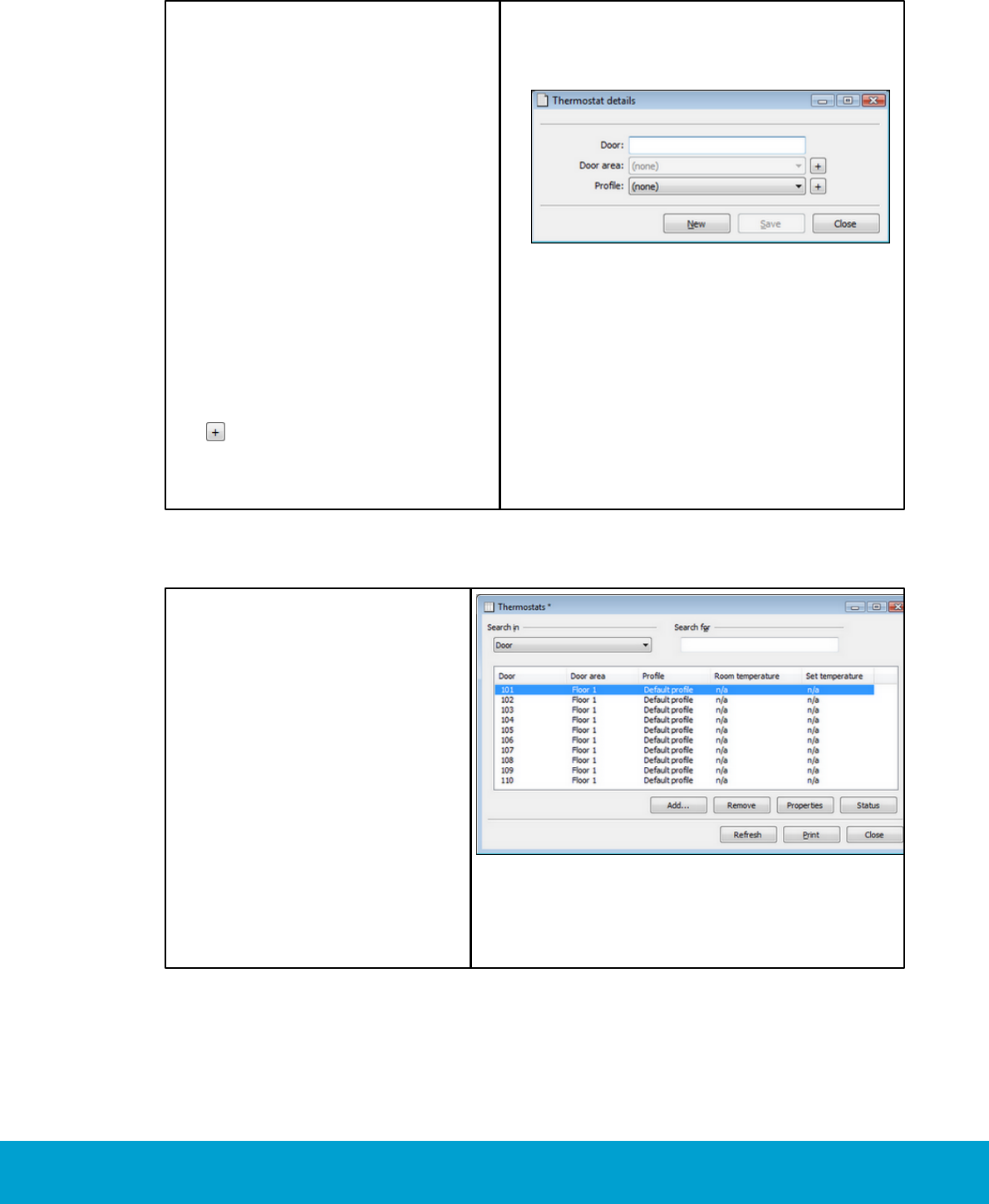
To add/modify a thermostat:
1. Double click on Thermostats
under the Lists tab in the
navigation window.
2. Click Add to add a new thermostat,
or Properties to modify an
existing thermostat.
3. At Door, enter the number of the
guest room where the thermostat
is located. If the same thermostat
properties should be valid for
thermostats in several rooms, add
all concerned room numbers (e.g.
101-103). If the concerned rooms
are not in sequence, separate them
with commas (e.g. 101-103, 105,
108-109).
4. At Profile, choose the applicable
thermostat profile in the
combobox. If no applicable
profile is available, click the
button to create a new one.
5. Click Save and Close, or New if
the Door field should be emptied
and a new thermostat be added.
Figure 22
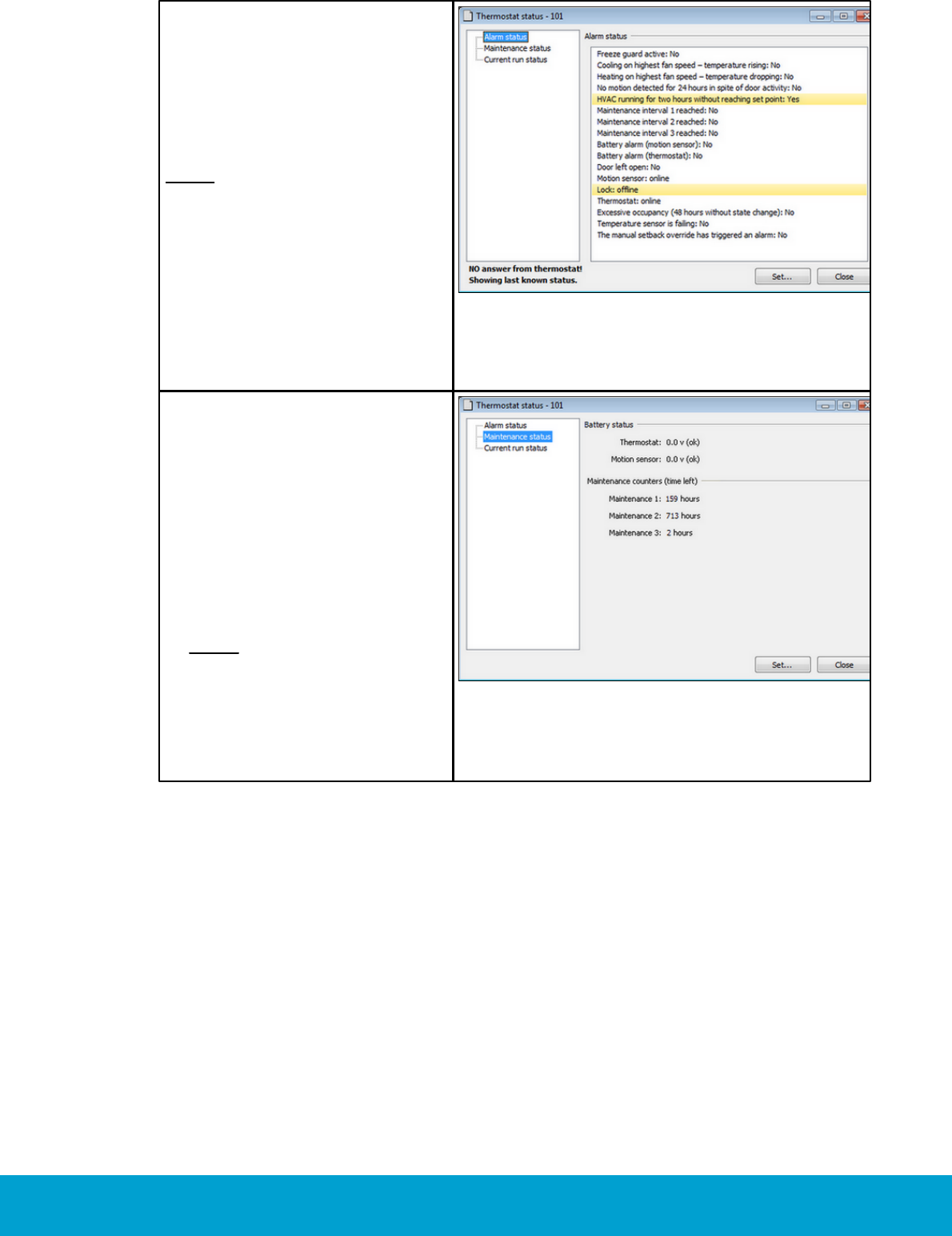
To check the status of a thermostat:
1. Double click on Thermostats
under the Lists tab in the
navigation window.
2. Mark the applicable thermostat
and click Status.
Figure 23
34
ASSA ABLOY Hospitality 66 8003 015-3
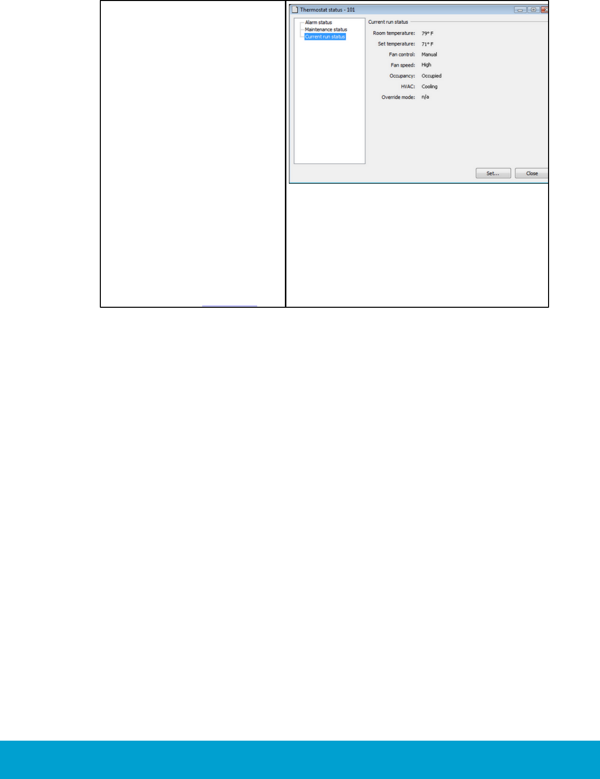
Under the Alarm
status tab:
3. Any alarms that have been
triggered for the concerned
thermostat are marked
with yellow.
Note: If the thermostat has not
answered with its current alarm
status, the last known status will
be shown instead (if there is one).
Figure 24
Under the Maintenance
status tab:
4. At Battery status, the
battery status of thermostat
(if battery operated) and
motion sensor is shown.
5. At Maintenance counters,
the time left for maintenance
counter 1, 2 and 3 respectively
are shown.
Note: The total numbers of
hours before the three different
maintenance alarms should be
triggered are specified at
Tools/Options/Energy
management/Maintenance.
Figure 25
35
ASSA ABLOY Hospitality 66 8003 015-3
Under the Current run
status tab:
6. At Room temperature,
the current room temperature
is shown.
7. At Set temperature, the
temperature which the guest
has set on the thermostat
is shown.
8. At Fan control, it is shown
whether the fan control is
‘auto only’ or ‘manual’.
9. At Fan speed, the current
fan speed (low, mid, high)
is shown.
10.At Occupancy, the occupancy
status is shown.
11.At HVAC, it is shown whether
the HVAC is ‘not running’,
‘cooling’ or ‘heating’.
12.At Override mode, it is
shown whether the thermostat
parameters are overridden.
Figure 26
36
ASSA ABLOY Hospitality 66 8003 015-3
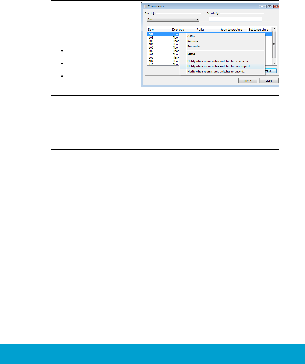
To notify users about room status:
If the Communication option is used, one or more users can be notified by e-mail and/
or SMS when the status of a room switches to occupied, unoccupied or unsold.
1. Double click on Thermostats
under the Lists tab in the
navigation window.
2. Right click on one or more
rooms in the thermostats list
and choose the applicable
one of
notify when room status
switches to occupied
notify when room status
switches to unoccupied
notify when room status
switches to unsold
Figure 27
3. In the Users <Thermostats> dialog that is shown, mark a user and click Select.
Only users which have been set up with e-mail address and/or cell phone number
in the User details dialog will be shown in the Users <Thermostats> dialog.
If the chosen user has been set up with both e-mail address and cell phone
number, you will get a question about what media that should be used; e-mail,
SMS or both.
4. If more users should be notified about the same room, repeat steps 2-3 for
the room.
See Installation instruction Communication option for more information about
the option.
37
ASSA ABLOY Hospitality 66 8003 015-3
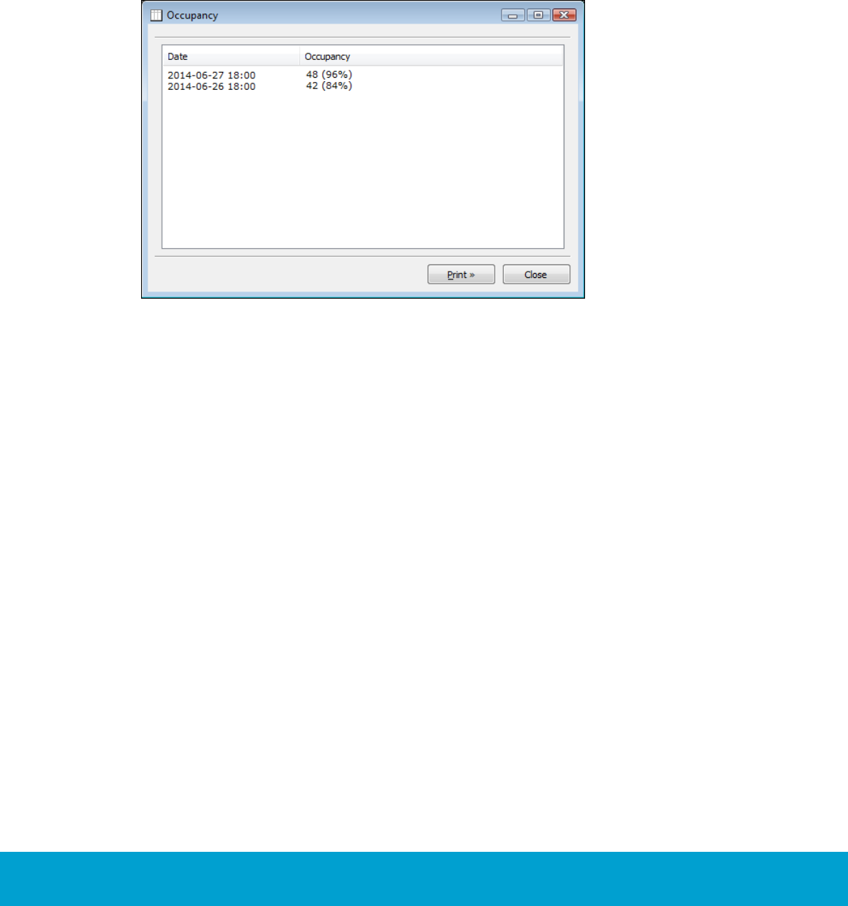
6. Occupancy report
The Occupancy report shows the number of rooms that are rented per day;
as a number and also as a percentage of the total number of rooms.
1. Double click on Ocupancy under the Reports tab in the navigation window.
Figure 28
38
ASSA ABLOY Hospitality 66 8003 015-3
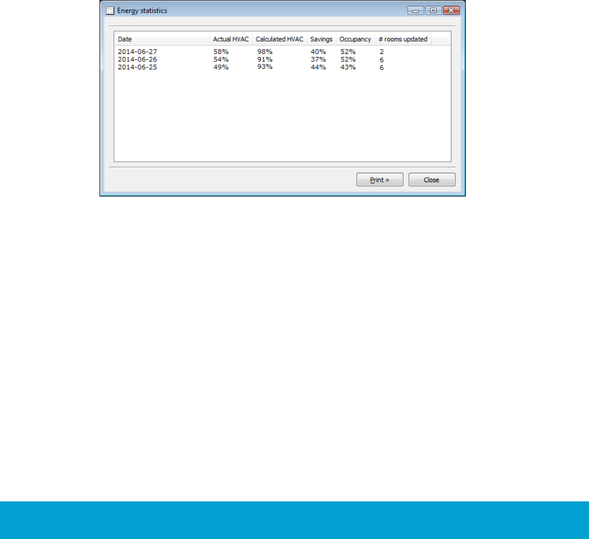
7. Energy statistics report
The Calculated HVAC column shows how much the HVAC units would run if the Orion
EMS option had not been used, i.e. if Orion EMS had not saved energy when the rooms
are unoccupied. The Calculated HVAC is continuously calculated every hour as the
total runtime for all HVAC units in occupied rooms divided by the total time these
rooms have been occupied.
The # rooms updated column shows how many rooms that have reported that they
run HVAC, i.e. events with runtime are sent from the room.
1. Double click on Energy statistics under the Reports tab in the
navigation window.
Figure 29
39
ASSA ABLOY Hospitality 66 8003 015-3
8. Tools/Options
At Tools/Options, there is a tab for Energy management, in turn containing the
tabs General, Maintenance and Housekeeping.
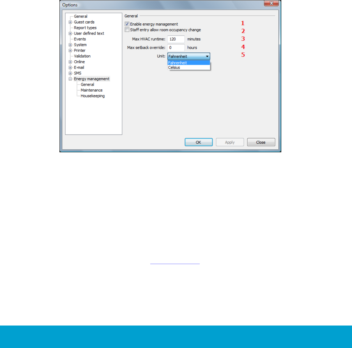
8.1 General
At Tools/Options/Energy management/General, the below parameters can be
modified; enter the applicable value(s) and click OK:
Figure 30
1. Enable energy management: This checkbox is automatically marked when the
Orion EMS option is set in the Visionline software. If the Orion EMS option should
temporarily be turned off, unmark 'Enable energy management' and click OK.
2. Staff entry allow room occupancy change: If this checkbox is marked, the room
will go to occupied state when motion is triggered if staff is in the room, i.e. when
a staff card has opened the room.
3. Max HVAC runtime: An alarm is triggered if a HVAC runs this long without
reaching the set temperature, i.e. the temperature which the guest has set
on the thermostat. Default is 120 minutes; the valid range is 30-300 minutes.
4. Max setback override: The setback override cannot exceed the number of hours
specified here; the valid range for ‘Max setback override’ is 0-99 hours. If the
40
ASSA ABLOY Hospitality 66 8003 015-3
default 0 hours is used, there is no limitation in time for the setback override
and it can be set until further notice.
5. Unit: The temperature unit (Fahrenheit/Celsius).
Note: Changes to the temperature unit will be broadcasted to all thermostats.
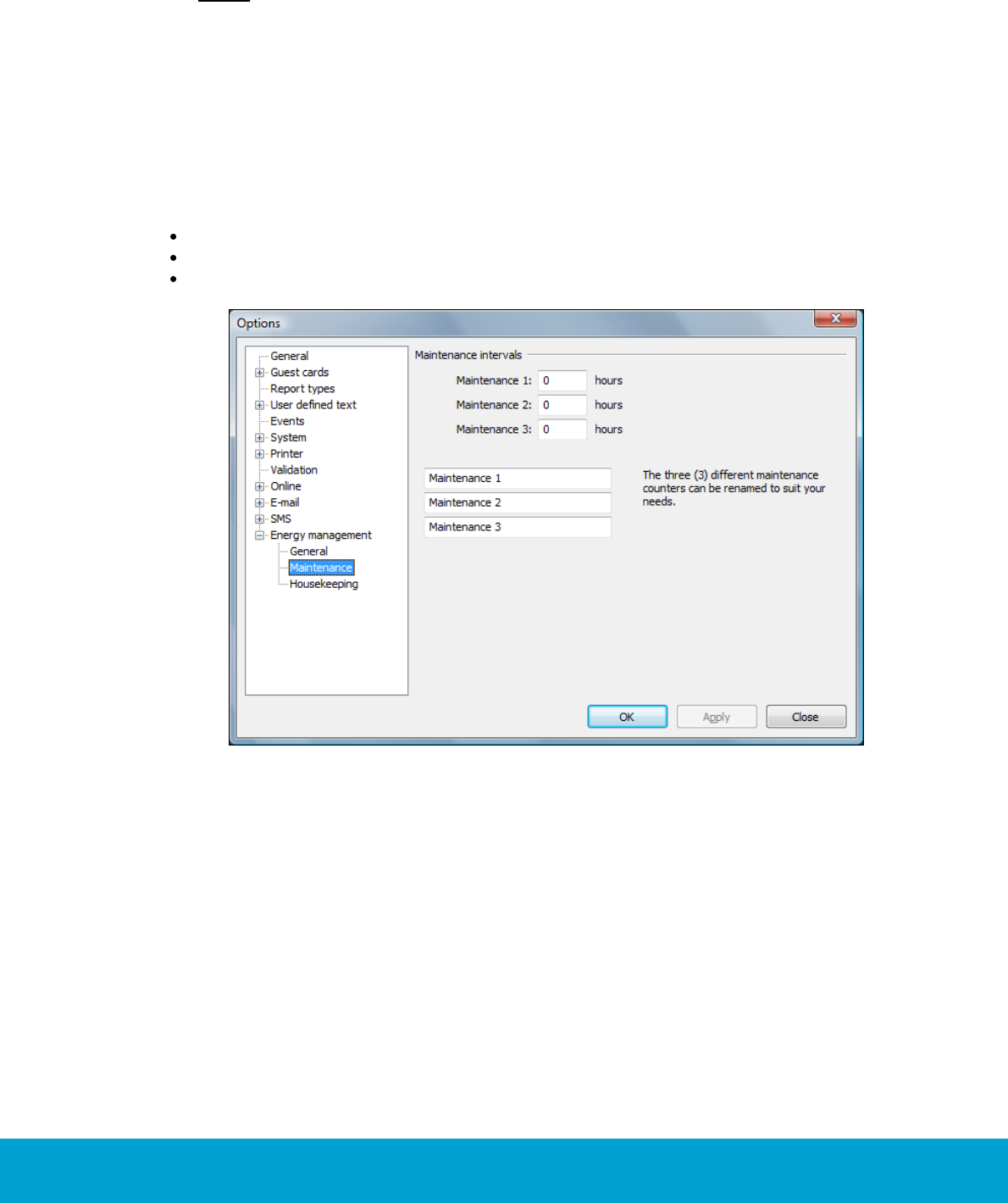
8.2 Maintenance
At Tools/Options/Energy management/Maintenance, it is possible to specify
three different thermostat maintenance intervals in hours; 0-65535 hours. This is
the number of hours of runtime that should pass before an alarm is triggered. It is also
possible to rename the three maintenance intervals.
Maintenance counter 1 is for fan time/total HVAC time
Maintenance counter 2 is for ‘cooling’
Maintenance counter 3 is for ‘cooling or heating’
Figure 31
1. Enter the applicable maintenance value(s) in hours.
2. If applicable, rename the three maintenance counters to your needs.
3. Click OK.
41
ASSA ABLOY Hospitality 66 8003 015-3
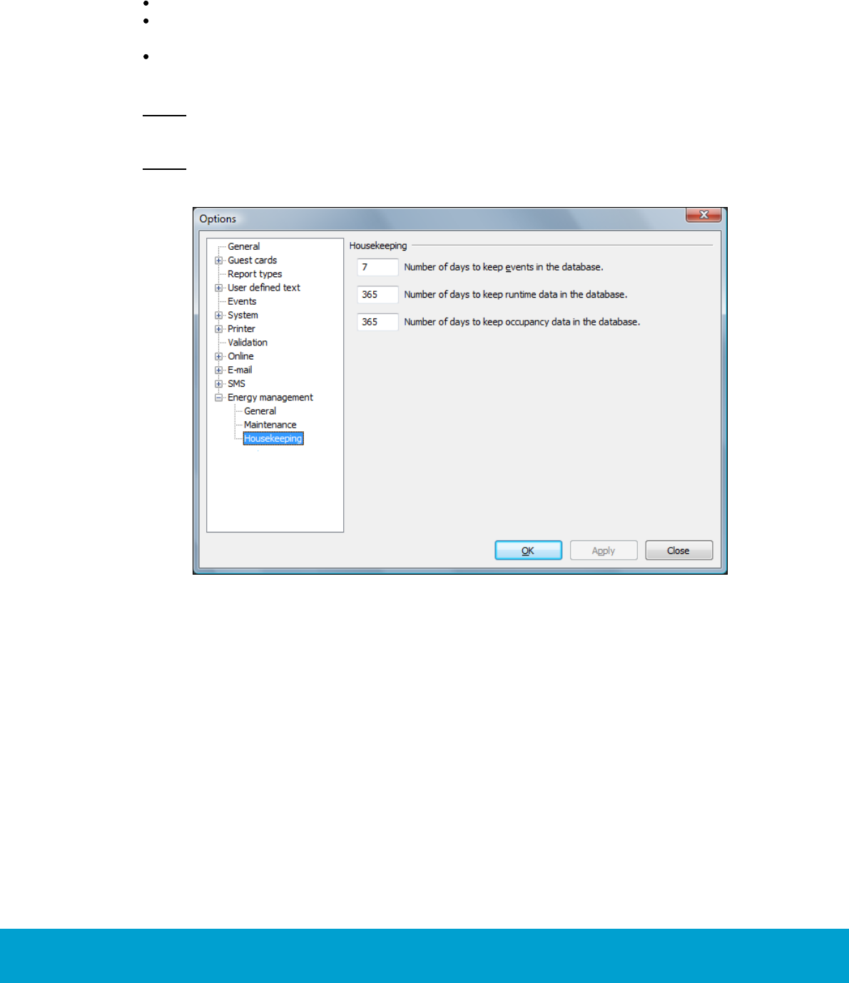
8.3 Housekeeping
At Tools/Options/Energy management/Housekeeping, it is possible to change
the default values for
number of days to keep events in the database (default 7; valid range 1-9999)
number of days to keep runtime data in the database (default 365;
valid range 1-9999)
number of days to keep occupancy data in the database (default 365;
valid range 1-9999)
Note: Events use a considerable amount of disk space, so the number of days to keep
events should be kept low.
Note: In the separate Orion EMS client, the housekeeping items are found at Tools/
Options/System/Housekeeping.
Figure 32
1. Enter the applicable values and click OK.

42
ASSA ABLOY Hospitality 66 8003 015-3
9. Orion EMS in SysMon
The maintenance software SysMon (System Monitor) is found in the Visionline
installation folder and also in the installation folder for the separate Orion EMS,
if the latter is applicable. It contains several dialogs, of which the ones below
are applicable for Orion EMS:
thermostats
online commands
broadcasts
room events
To open SysMon:
1. Double click on SysMon.exe in the installation folder. Tip: Make a shortcut to
SysMon since this will be extensively used. Note: The Broadcasted commands
dialog is not automatically updated; press F5 to refresh it manually.
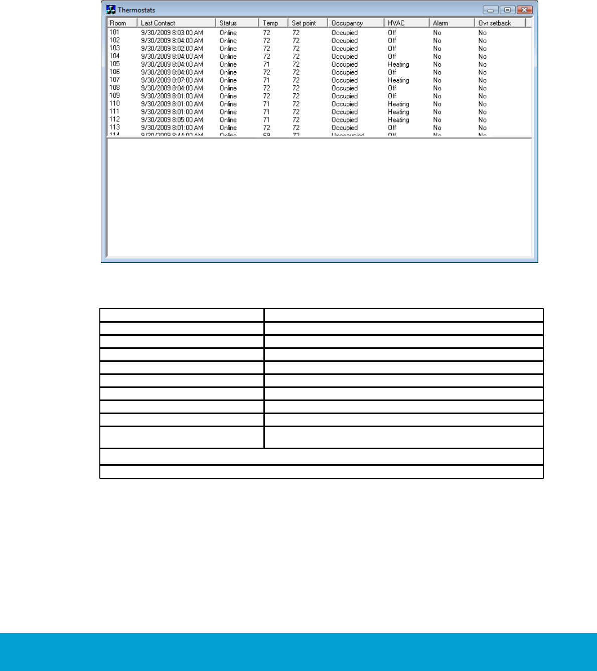
43
ASSA ABLOY Hospitality 66 8003 015-3
9.1 Thermostats
The Thermostats dialog of SysMon gives a good overview of all thermostats;
if there are any alarms, if any thermostats have been overridden etc.
1. Go to View/Thermostats.
Figure 33
Column
Description
Room
Room number
Last contact
Time when last telegram was sent from the thermostat
Status
Online/Offline
Temp
Room temperature
Setpoint
The temperature which the guest has set on the thermostat
Occupancy
Unsold/Unoccupied/Occupied
HVAC
Off/Cooling/Heating
Alarm
Yes/No
Ovr setback
This column shows if the thermostat in the concerned room has
been overridden; Yes/No
Table 8
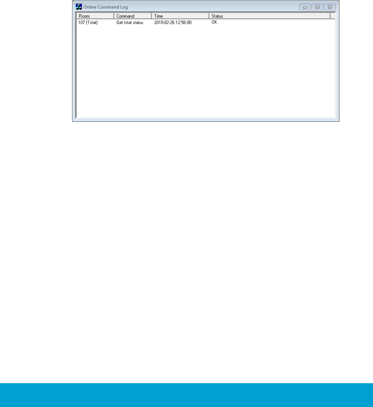
44
ASSA ABLOY Hospitality 66 8003 015-3
9.2 Online commands
The Online Command Log dialog of SysMon shows commands that have been sent to
the thermostats. The online commands are listed in reverse chronological order.
1. Go to View/Online Commands.
Figure 34
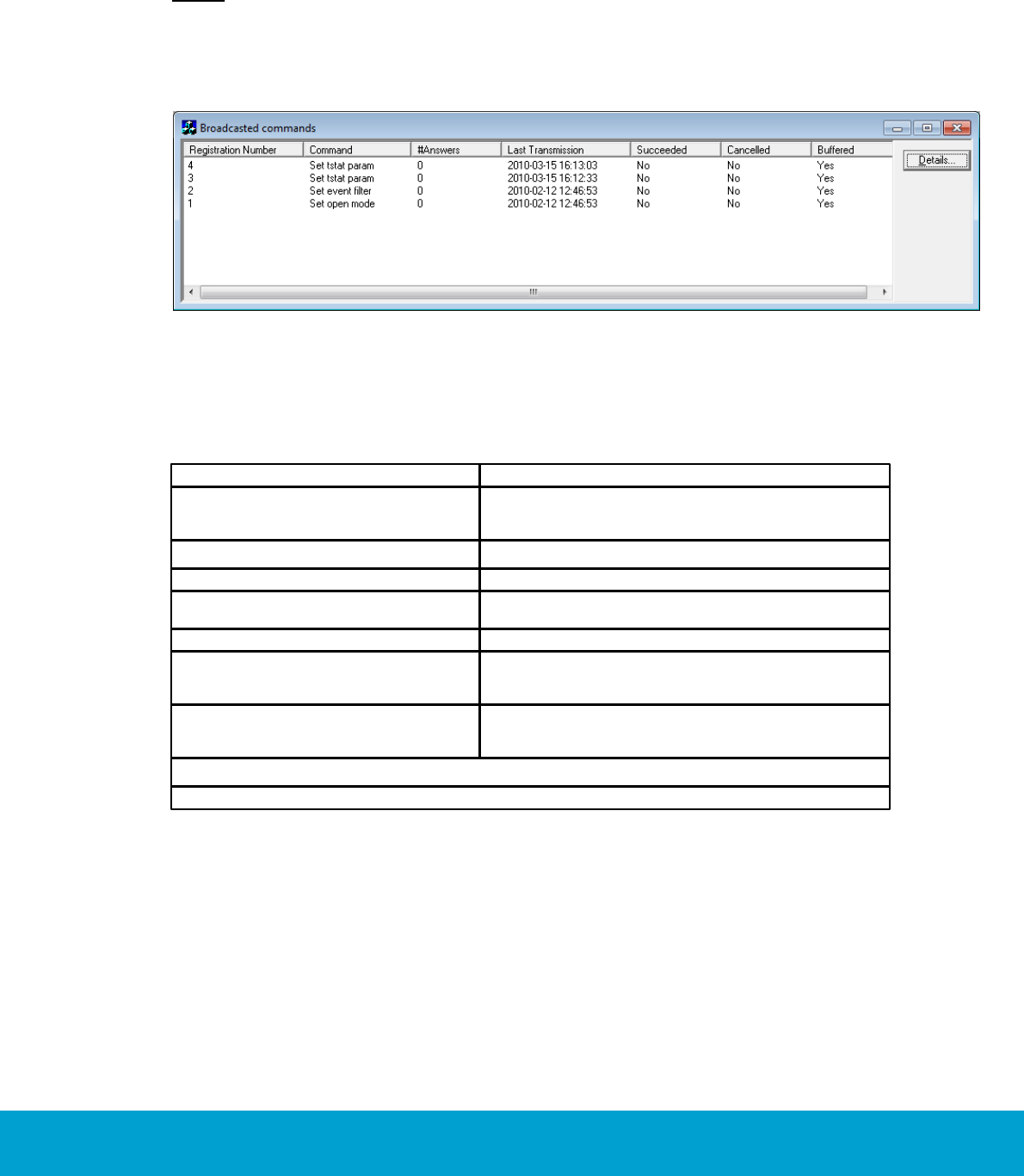
45
ASSA ABLOY Hospitality 66 8003 015-3
9.3 Broadcasts
The Broadcasted commands dialog shows all commands that have been broadcasted
to the thermostats. The broadcast commands are listed in reverse chronological order.
Note: The Broadcasted commands dialog is not automatically updated; press F5 to
refresh it manually.
1. Go to View/Broadcasts.
Figure 35
2. To see details for a certain command, mark it in the list and click Details.
3. A Broadcast Answers dialog will be shown, with the concerned thermostats
or locks (depending on command) and their answer time.
Column
Description
Registration Number
Uniquely identifies the broadcasted command. The
registration number will be shown in the events the
command generates.
Command
# Answers
The number of locks that have answered the command
Last Transmission
Timestamp when the command was last broadcasted;
originally or due to a retry.
Succeeded
Yes if all locks answered
Cancelled
Yes if the command was cancelled by another broadcast;
e.g. a new Set-Time command cancels any previous
Set-Time command.
Buffered
Yes if the command has timed out. It has then been
buffered as a single-cast command for all locks that
have not answered.
Table 9
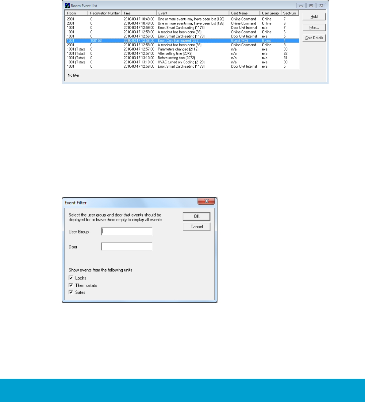
46
ASSA ABLOY Hospitality 66 8003 015-3
9.4 Room events
The Room Event list dialog shows events related to the lock or to the in-room devices
such as thermostat or motion sensor.
1. Go to View/Room events.
Figure 36
2. If large amounts of events are continuously presented, there is a possibility to
"freeze" the presentation of events to be able to look closer at a certain event.
In this case, click the Hold button.
To filter the room events:
1. Click the Filter button in the Room Event List dialog; the dialog to the right
will be shown.
2. Enter the applicable filtering information and click OK. The result is presented
in a room event list.
Figure 37
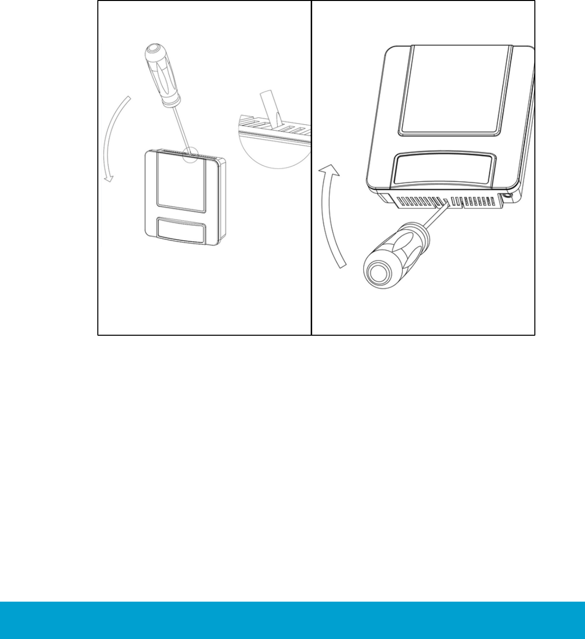
47
ASSA ABLOY Hospitality 66 8003 015-3
10. Maintenance
10.1 To disassemble a thermostat
1. Use a flathead screw driver to loosen the
thermostat; bend the locking arms and in the
same time pull carefully.
Figure 38
2. Use the flathead screw driver to bend the
locking arm at the bottom of the thermostat;
at the same time pull carefully.
Figure 39
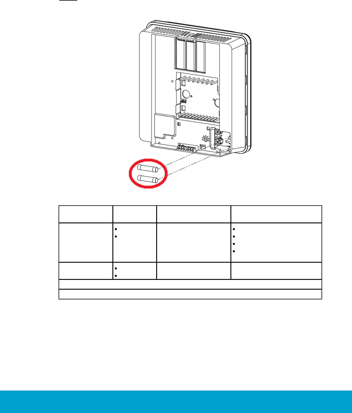
48
ASSA ABLOY Hospitality 66 8003 015-3
10.2 To replace a fuse
The thermostat has two fuses which are located as in Figure 40.
Note: To replace a fuse, the thermostat must be disconnected from the wall plate.
Figure 40
How do I know if
the fuse has blown?
What does the
fuse protect?
Upper fuse
5x20mm
2.0AF
The thermostat
appears to be dead.
Reversing valve output
Cool output
Heat output
Internal power supply
of the thermostat
Lower fuse
5x20mm
6.3AT
The fan outputs
stop working.
The fan outputs
Table 10

49
ASSA ABLOY Hospitality 66 8003 015-3
Appendix A: Quick reference of technical data
Note: If external motion sensor is applicable, see Installation manual Orion High Voltage
Thermostat for technical data and information about installation.
Dimensions (WxHxD)
112 x 117 x 35 mm (4 13/32" x 4 19/32" x 1 3/8")
Mains voltage input
Universal voltage input 100VAC-277VAC; 50/60Hz;
rated impulse voltage: 4kV
Switch input
Door switch - 1 exterior/1 interior
Multifunction input
Motion sensor/card switch/pipe temp sensor
High voltage outputs
- G1 (Fan 1): Type 1.B action. Max load 3A (3FLA/18LRA)
- G2 (Fan 2): Type 1.B action. Max load 3A (3FLA/18LRA)
- G3 (Fan 3): Type 1.B action. Max load 3A (3FLA/18LRA)
- RV (reversing valve): Type 1 action. Max load 0.5A
- Y (cooling/compressor): Type 1 action. Max load 0.5A
- W (heating): Type 1 action. Max load 0.5A
Low voltage outputs
- Proportional 0-10V; heating
- Proportional 0-10V; cooling
- Switch output (max 24V AC/DC, SELV, max 0.1A)
Temperature sensor
Integrated in thermostat
Temperature display
Configurable: room temperature (default) or
guest setting
Temperature display range
2-digit display
Adjustable setpoint
temperature range
17°C - 32°C / 62F - 90F
Environment
Normal indoor environment - Pollution degree 2
Operating temperature range 0°C - 55°C / 32F -130F
Temperature sensor
Integrated in thermostat
Service device
Orion Service software and
service cable RJ12 to 3.5mm stereo jack
Radio (RF) signals
ZigBee 2006
Lock to thermostat:
Door open - staff card
Door open - guest card
Door open from inside
Door closed
Deadbolt thrown/released
Thermostat to lock:
Room occupied
Motion sensor to thermostat:
Motion detected
Battery status
Thermostat to motion sensor:
Turn off when the room is occupied and door is closed
Turn on when the door is opened again
50
ASSA ABLOY Hospitality 66 8003 015-3
Appendix A: Quick reference of technical data
Thermostat deadband
Configurable 1-3 °F; default is 2 °F
Heat/cool switching deadband
Configurable 2-4 °F; default is 3 °F
Freeze guard
39 °F / 4 °C
Refresh cycle
Optional
Humidity
Optional
Intelligent switch
Configurable: Disabled/use RV output/use G2 output;
default is disabled
Room not occupied timer
Configurable 1-120 minutes; default is 8 minutes
Room not sold timer
Configurable 12-24 hours; default is 16 hours
Compressor delay
(dwell-off time)
Default is that the dwell-off time is off; it is only applicable
when 'heat pump' is chosen as HVAC type.
In the 'heat pump' case, the thermostat will automatically
force the dwell-off time to be on - it is then 5 minutes and
cannot be changed. The dwell-off time prevents short-cycling
of the compressor.
Required Visionline version
1.15.0 or higher for full functionality of
thermostat profiles
Required Orion Service version
1.3.0 or higher
Table A1

51
ASSA ABLOY Hospitality 66 8003 015-3
Appendix B: Troubleshooting
FCU = fan coil unit
PTAC = Package Terminal Air Conditioner
A/C Unit not blowing hot/cold air
A/C unit not blowing hot/cold air
1. Confirm at the thermostat that the heat or cool symbol is displayed.
a. If the symbol is on, the call has been sent from the thermostat
to the FCU/PTAC.
b. If the symbol is not on, change the set temperature to be more than
2 degrees different from the actual temperature to engage the heat/cool call.
Note: For cool, there is a 5 minute compressor delay after the unit is turned
on, to prevent short-cycling.
2. Confirm that voltage is applied at the HVAC unit heat/cool inputs.
a. If accurate voltage is applied to the correct inputs and outputs,
additional troubleshooting must be done at the FCU/PTAC.
b. If no voltage is applied to the correct inputs, a voltage drop has
occurred between the thermostat and the FCU/PTAC. Check the wiring.
Note: See Installation manual Orion High Voltage Thermostat for information about
the heat/cool relays used.
Fan speed not working
1. Confirm the configuration of the thermostat profile with fan speeds. Make sure
that the wiring is in accordance with these settings. Change from Auto and test
the individual fan speeds.
a. If one of the fan speeds is not working, confirm that voltage is applied at
the FCU/PTAC for that fan speed. If voltage is applied to the correct fan speed,
additional troubleshooting must be done at the FCU/PTAC.

52
ASSA ABLOY Hospitality 66 8003 015-3
Appendix B: Troubleshooting
Thermostat has no power
1. Confirm that the thermostat has power applied to the correct wires. If the correct
power is applied, make sure that the thermostat is connected correctly. If the
thermostat is plugged in incorrectly, it can be damaged and needs replacement.
Room is not going into Occupied state
1. Was a staff card used to open the door (for systems with locks monitoring the
door)? If so, the room will not enter occupied state on motion. Press a key on
the thermostat and check the occupied status again.
2. Check the online status of the lock and the motion sensor.
a. If the door lock or the motion sensor is offline, use an Orphan Join card for
the lock and recycle the power for the motion sensor.
b. If the door is still offline, follow the necessary steps to discover the lock back
to the thermostat.
c. If the motion sensor is still offline, replace the batteries.
d. If the motion sensor is still offline after this, follow the necessary steps to
discover the motion sensor back to the thermostat.
3. If the RF door switch is applicable, confirm that door open and door closed events
are logged at the thermostat. Also use the Diagnostics feature in Orion Service
to confirm that the door position is shown correctly; Open and Closed.
4. Make sure that the configuration settings at the thermostat are accurate, including
correct relay configuration for internal door switch and external door switch. If
neither is used, make sure that Normally Closed is selected.

53
ASSA ABLOY Hospitality 66 8003 015-3
Appendix B: Troubleshooting
A/C unit cooling when calling for heat (and vice versa)
1. If the unit is a heat pump, make sure that the thermostat is properly configured to
control the heat pump. See Daily use manual Orion High Voltage Thermostat for
proper configuration of a heat pump.
2. If the unit is not a heat pump, or if the thermostat is correctly configured, check the
outputs of the thermostat to ensure that it is calling for heat or cool properly.
a. First check the outputs at the thermostat.
i. If OK, check the outputs of the thermostat at the connection to the HVAC
unit. It is possible that the wiring is crossed or somehow incorrect.
ii. If all is OK, the property needs to have their HVAC technician check the unit.
b. If the thermostat outputs are incorrect:
i. First check the configuration of the thermostat by using Orion Service to read
out the parameters of the thermostat; do not just rely on looking at the
parameters in the Visionline or Orion EMS software. If the parameters are
incorrect, make the necessary changes.
ii. Connect a new thermostat to see if the problem disappears. If it does, replace
the thermostat. If the problem stays, there is a problem with the wiring or
parameters that must be fixed.
Fan continues to run even when the thermostat is turned off
1. First, wait a couple of minutes to see if the fan does eventually turn off. Some air
handlers have a built-in function that keeps the fan running for a time after the
heating or cooling function is turned off.
2. Secondly, use Orion Service to check the parameters of the thermostat – ensure
that the ‘Fan on when satisfied’ function is set to ‘no’.
3. Finally, test the outputs of the thermostat to see which ones that are on. If a fan
output is active and the thermostat is not calling for fan (use the Diagnostics
feature of Orion Service to confirm that the thermostat is not calling for fan),
change the thermostat as it has a stuck relay. If no fan output is active, check all
other outputs to find out if any are active. It is possibly a crossed or shorted wire.

54
ASSA ABLOY Hospitality 66 8003 015-3
Appendix C: Read more
Document name:
Document number:
Installation instruction Communication option
66 5013 026
Installation manual Orion High Voltage Thermostat
66 8003 016
Revision history
Date
Change
By
November 7, 2014
First release
KG
January 11, 2016
Updated layout
KG
October 12, 2016
Modified maximum value for 'room not
occupied timer' to 120 minutes
KG

55
ASSA ABLOY Hospitality 66 8003 015-3
E-mail: apac.hospitality@assaabloy.com
ASSA ABLOY Hospitality APAC
Phone: +65 6305 7670
ASSA ABLOY Hospitality EMEA
ASSA ABLOY Hospitality North America
Phone: +47 69 24 50 00
E-mail: emea.hospitality@assaabloy.com
E-mail: lam.hospitality@assaabloy.com
Phone: +1 972 907 2273
ASSA ABLOY Hospitality Latin America
E-mail: northam.hospitality@assaabloy.com
Phone: +52 55 36 40 12 00
www.assaabloyhospitality.com