ASSALOY Global Solutions Norway AS 7001CC1 PCBA 7001 User Manual Installation instruction option Auto update
ASSA ABLOY Hospitality AS PCBA 7001 Installation instruction option Auto update
Users Manual
1 66 1402 203-5
66 1402 203-1
FCC (Federal Communications Commission) statements
This device comply with Part 15 of the FCC Rules. Operation is subject to the following two conditions:
1) The BLE Module may not cause harmful interference, and
2) The BLE Module must accept any interference received, including interference that may cause undesired operation.
Important note: To maintain compliance with FCC´s RF exposure guidelines, this equipment should be installed and operated with minimum distance 20 cm between the radiator and your body.
Use only the supplied antenna.
This equipment complies with FCC radiation exposure limits set forth for an uncontrolled environment. This transmitter must not be co-located or operating in conjunction with any other antennas or transmitters.
Changes or modifications not expressly approved by the party responsible for compliance could void the user's authority to operate the equipment.
Note: This equipment has been tested and found to comply with the limits for a Class B digital device, pursuant to Part 15 of the FCC Rules. These limits are designed to provide reasonable protection against harmful
interference in a residential installation. This equipment generates, uses and can radiate radio frequency energy and, if not installed and used in accordance with the instructions, may cause harmful interference to radio
communications. However, there is no guarantee that interference will not occur in a particular installation. If this equipment does cause harmful interference to radio or television reception, which can be determined by
turning the equipment off and on, the user is encouraged to try to correct the interference by one or more of the following measures:
- Reorient or relocate the receiving antenna.
- Increase the separation between the equipment and receiver.
- Connect the equipment into an outlet on a circuit different from that to which the receiver is connected.
- Consult the dealer or an experienced radio/TV technician for help.
The concerned end product must be labeled to say ‘Contains FCC ID: Y7V-7001CC1’.
IC (Industry Canada) statements
This device comply with Industry Canada licence-exempt RSS standard CAN ICES-3 (B)/NMB-3(B) B. Operation is subject to the following two conditions:
1) The BLE Module may not cause interference, and
2) The BLE Module must accept any interference, including interference that may cause undesired operation of the device.
Important note: To comply with Industry Canada RF radiation exposure limits for general population, the antennas used for these transmitters are exempted from Routine Evaluation
Limits – SAR Evaluation in accordance with RSS-102 section 2.5.1.
Under Industry Canada regulations, this radio transmitter may only operate using an antenna of a type and maximum (or lesser) gain approved for the transmitter by Industry Canada. To reduce potential radio
interference to other users, the antenna type and its gain should be so chosen that the equivalent isotropically radiated power (e.i.r.p.) is not more than that necessary for successful communication. This BLE Module
‘IC: 9514A-7001CC1’ has been approved by Industry Canada to operate with the antenna type listed below with the indicated maximum permissible gain and required antenna impedance. Antenna types not included
in this list, having a gain greater than the maximum gain indicated for that type, are strictly prohibited for use with this device.
Name/Model
Gain
Impedance
Inverted F-antenna
3.0 dBi
50 ohm
The term "IC" before the equipment certification number only signifies that the Industry Canada technical specifications were met. The concerned end product must be labeled to say ‘Contains IC: 9514A-7001CC1’.
Déclarations d’Industry Canada
Cet équipement est conforme aux normes d’exemption de licence RSS d’Industry Canada CAN ICES-3 (B)/NMB-3(B) B. Son utilisation est soumise aux deux conditions suivantes:
1) Le module BLE ne doit pas provoquer d’interférence, et
2) Le module BLE doit accepter toute interférence, y compris des interférences susceptibles de provoquer un fonctionnement indésirable de l’équipement.
Remarque importante: Pour respecter les limites d’exposition aux radiofréquences d’Industry Canada pour le grand public, les antennes utilisées pour ces émetteurs-transmetteurs sont exemptées des limites
d’évaluation de routine – évaluation SAR, conformément à la norme RSS-102 section 2.5.1.
Conformément aux réglementations d’Industry Canada, cet émetteur radio peut uniquement fonctionner à l’aide d’une antenne dont le type et le gain maximal (ou minimal) pour ces émetteurs-transmetteurs sont
approuvés par Industry Canada. Pour réduire le risque d'interférence éventuelle pour les autres utilisateurs, le type et le gain de l'antenne doivent être choisis de manière à ce que la puissance isotrope rayonnée
équivalente (p.i.r.e.) ne soit pas supérieure à la puissance nécessaire à une bonne communication. Ce module BLE ‘IC: 9514A-7001CC1’ a été approuvé par Industry Canada pour une utilisation avec les types
d’antenne indiqués ci-dessous avec le gain maximum autorisé indiqué et l’impédance d’antenne requise. Il est strictement interdit d’utiliser avec cet appareil un type d’antenne ne figurant pas dans cette liste ou ayant
un gain supérieur au gain maximum indiqué pour ce type.
Appellation/Modèle
Gain
Impédance
Antenne F inversée
3.0 dBi
50 ohm
Le terme « IC » devant le numéro de certification de l’équipement signifie seulement que les spécifications techniques d’Industry Canada ont été respectées. Le produit final concerné doit porter une étiquette avec la
mention: ‘Contient IC: 9514A-7001CC1’.
Quick installation guideline – Signature lock with housing BLE
2 66 1402 203-5
66 1402 203-1
Introduction
With the Mobile Access option set in the Visionline software, the BLE technology (Bluetooth® Low Energy) is used for exchanging data. Instead of using
cards for access, mobile keys are used. The guest must have a Bluetooth® telephone which is registered with an Endpoint ID, and an app for opening the door.
A 3G RFID Signature lock is upgraded to BLE usage by following the steps in this instruction.
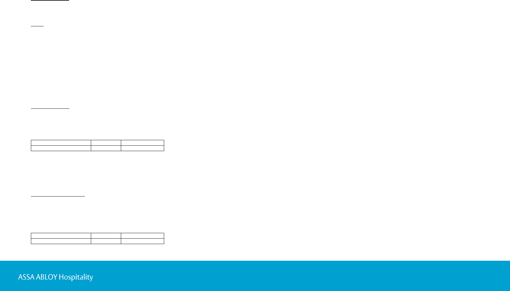
Parts for the upgrade
Pos
Description
Quantity
1
Y-cable ZigBee&BLE for Classic
1
2
Housing BLE
1
3
Shield BLE
1
4
Screw standoff
2
5
Cable sleeve
1
Tools for the upgrade
Screwdriver Torx TR20
Lock Service 3G; minimum version 1.1.1
USB interface 3G; complete ordering name
is cable RJ12 to USB adapter (for 3G)
Service cable; complete ordering name
is service cable RJ12 for 3G RFID LCU
& E-cylinder
Figure 1: Signature kit, housing BLE
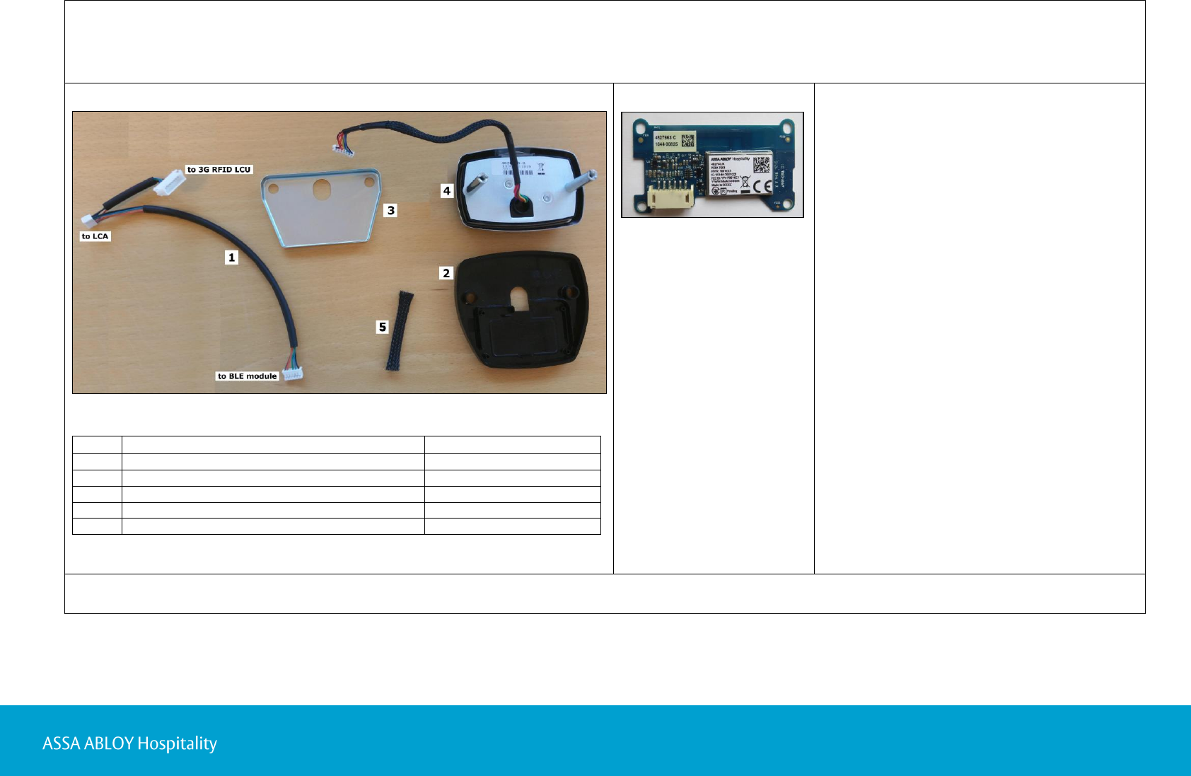
Figure 2: BLE module
Table 1: Contents of ’Signature kit, housing BLE’
The information in this document is subject to change at the sole discretion of ASSA ABLOY without notice. Any use, operation or repair in contravention of this document is at your own risk. ASSA ABLOY does not assume any responsibility
for incidental or consequential damages arising from the use of this document. All information and drawings in this document are the property of ASSA ABLOY. Unauthorized use and reproduction is prohibited. VingCard and Elsafe are registered
trademarks of ASSA ABLOY. For R&TTE statements for the BLE module, see ‘Installation instruction Mobile access option’.
3 66 1402 203-5
66 1402 203-1
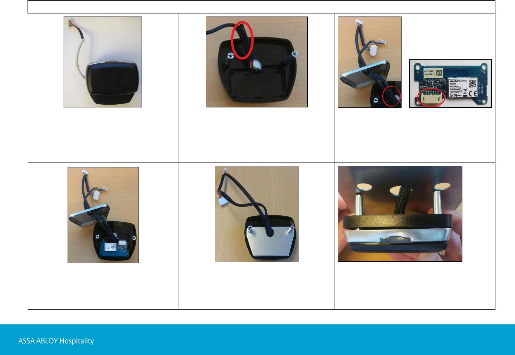
3. Thread the cable sleeve onto
the 3G RFID LCU reader cable.
4. Thread the Y-cable ZigBee&BLE for Classic (from
now on called ‘Y-cable’) through the shield BLE
and through the cable sleeve, which will now
contain two cables (3G RFID LCU reader cable
and Y-cable).
5. Connect the Y-cable to the BLE module.
6. Mount the BLE module in the housing BLE.
7. Push the cable sleeve all the way down
to the housing BLE.
8. Thread the shield BLE over the spacers (or
screws standoff if applicable) and all the way
down to the housing BLE.
9. Thread the cable sleeve through the middle hole
of the door cut-out and the spacers (or screws
standoff if applicable) through the outer holes
of the door cut-out.
Figure 4
1. If the door thickness requires it: exchange
the regular spacers on the back of the
LCU Signature RFID assy with the screws
standoff (item number 4 in Figure 1).
2. Mount the LCU Signature RFID assy (3G)
in the housing BLE.
Figure 5
Figure 9
Figure 10
Figure 4
Figure 6
Figure 7
Figure 8
Procedure
4 66 1402 203-5
66 1402 203-1
10. Mount the housing BLE including
the LCU Signature RFID assy (3G)
on the door; the spacers (or the
screws standoff) on the back of
the LCU Signature RFID assy (3G)
are in step 11 fastened together
with the mounting frame (full name
mounting frame inside Signature).
11. Use a screwdriver Torx TR20
(or Torx T20) to fasten the mounting
frame with two screws on the back of
the door.
Note: Make sure to align the mounting
frame on both sides before fastening it.
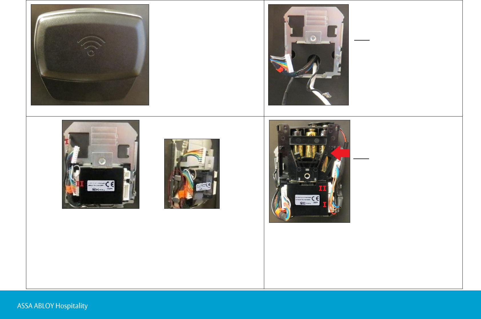
12. Snap the LCA 6343 onto the mounting frame (hide the
lock motor cable and the 3G RFID LCU reader cable behind it).
13. Connect the cables according to Figure 13. Use the tabs on the sides
of the mounting plate to keep the cables in place; see Figure 14.
I. Connect the ground cable to the connector at the mounting frame.
II. Connect the lock motor cable to the 10-pin connector on the left side
of the LCA 6343.
14. Snap the battery protection (marked with an arrow in Figure 15)
onto the mounting frame.
15. Connect the LCA part of the Y-cable to the 7-pin connector on
the right side of the LCA 6343; marked ‘I’ in Figure 15.
16. Load the battery holder 4.5V with 3 AA batteries.
17. Mount the battery holder 4.5V in the battery protection with the
batteries standing as shown in Figure 15.
18. Connect the battery cable (full name: battery cable Signature/
19. Classic 4.5V/Classic 9V) to the 2-pin connector on the right side
of the LCA 6343; marked ‘II’ in Figure 15.
Figure 11
Figure 12
Figure 13
Figure 14
Figure 15
Note: The plug parking on the left side
of the battery protection cannot be used
since the cables are too short.
5 66 1402 203-5
66 1402 203-1
20. Use the tabs on the sides of the mounting plate
to keep the cables in place; see Figure 16.
Figure 17
21. Thread the battery cover
Signature onto the
mounting frame.
22. Use a screwdriver Torx TR20
to fasten the battery cover
Signature.
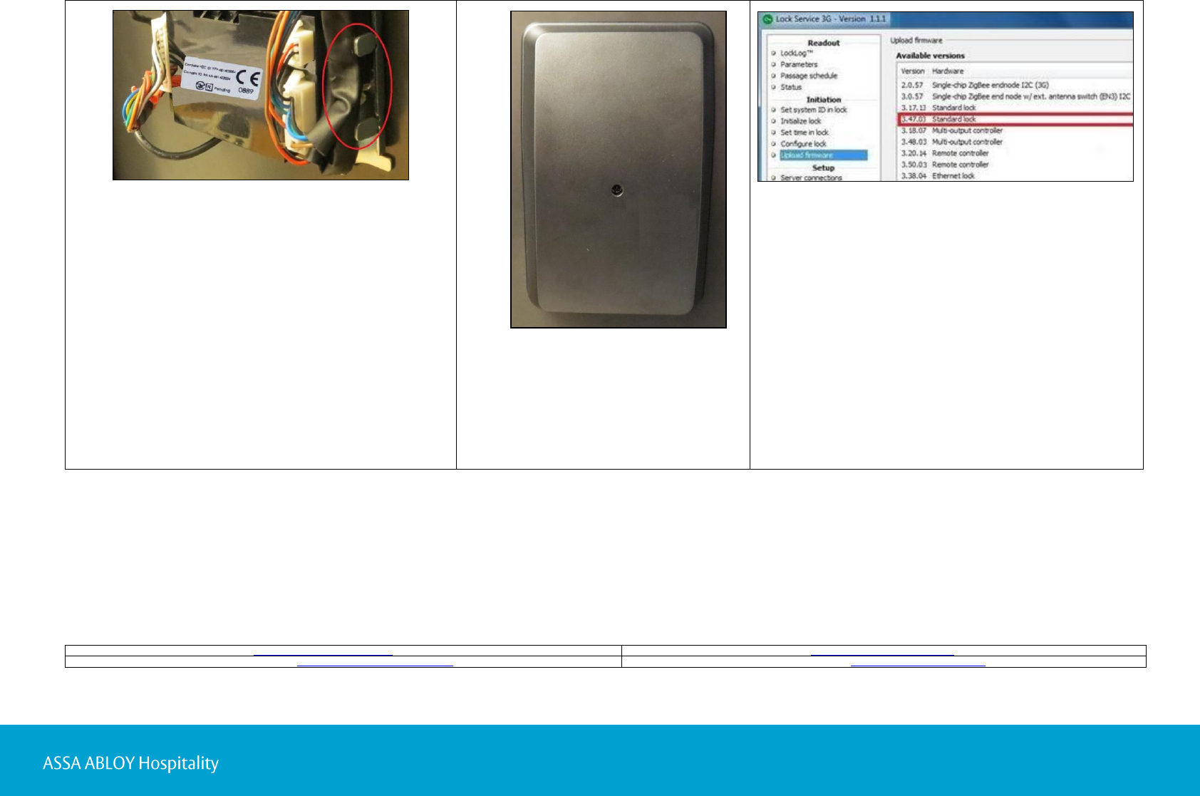
23. Use a service cable and Lock Service 3G
to upload the BLE lock firmware, 3.47.XX.
The firmware is included under the Upload
firmware alternative in Lock Service 3G;
see Quick reference guide Lock Service 3G
for details. If a later firmware version is
available, first use the Download firmware
alternative; see Quick reference guide Lock
Service 3G for details.
ASSA ABLOY Hospitality APAC: e-mail apac.hospitality@assaabloy.com, phone +65 6305 7670
ASSA ABLOY Hospitality EMEA: e-mail emea.hospitality@assaabloy.com, phone +47 69 24 50 00
ASSA ABLOY Hospitality North America: e-mail northam.hospitality@assaabloy.com, phone +1 972 907 2273
ASSA ABLOY Hospitality Latin America: e-mail lam.hospitality@assaabloy.com, phone +52 55 36 40 12 00
Figure 18
Figure 16