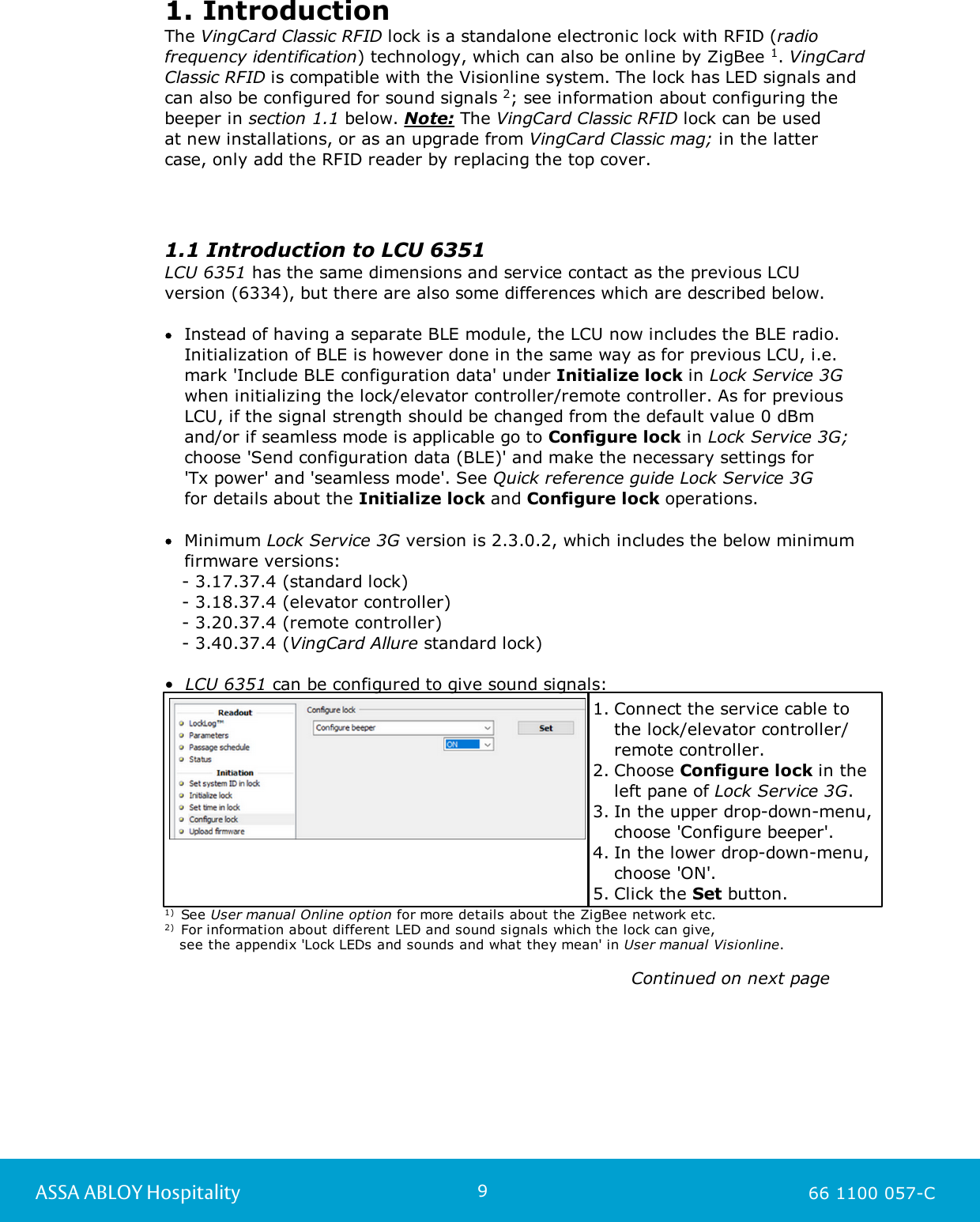
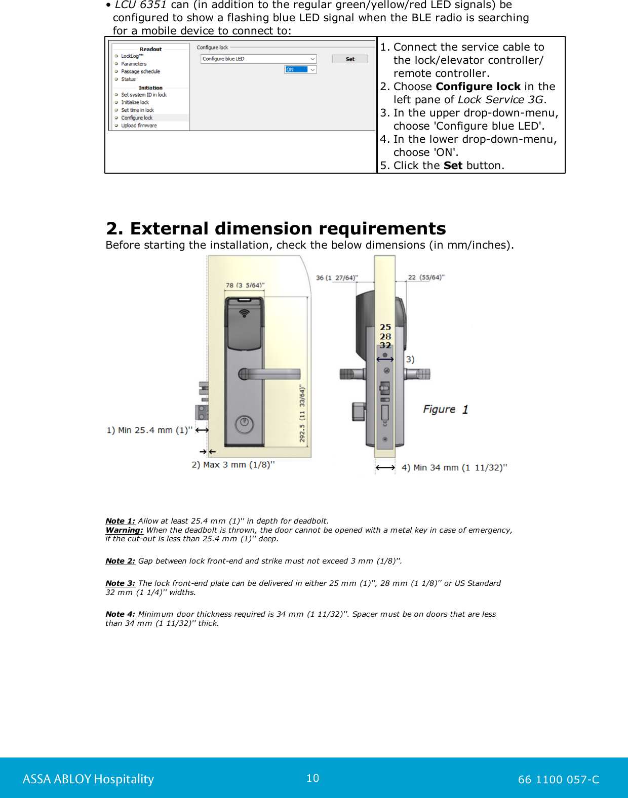
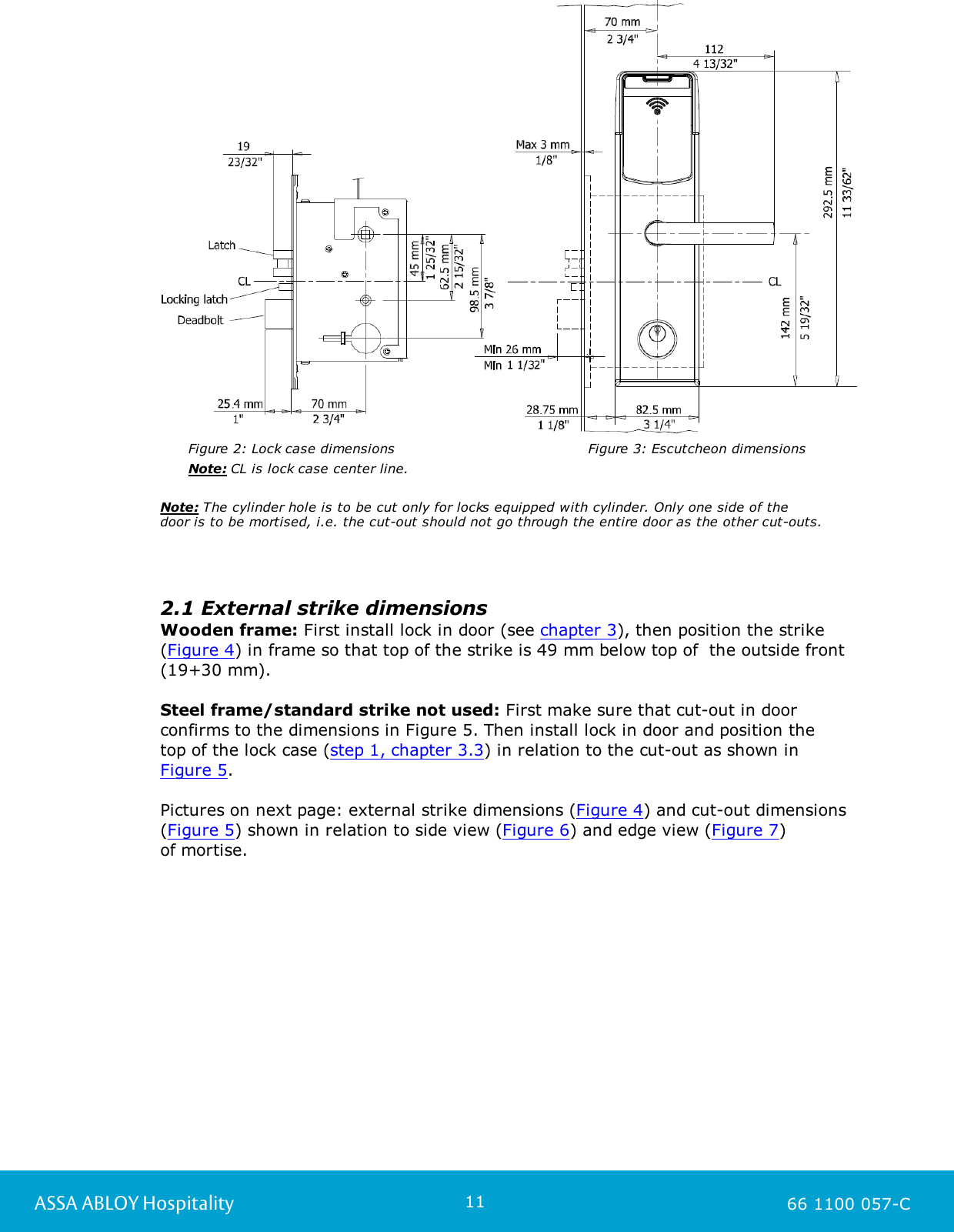
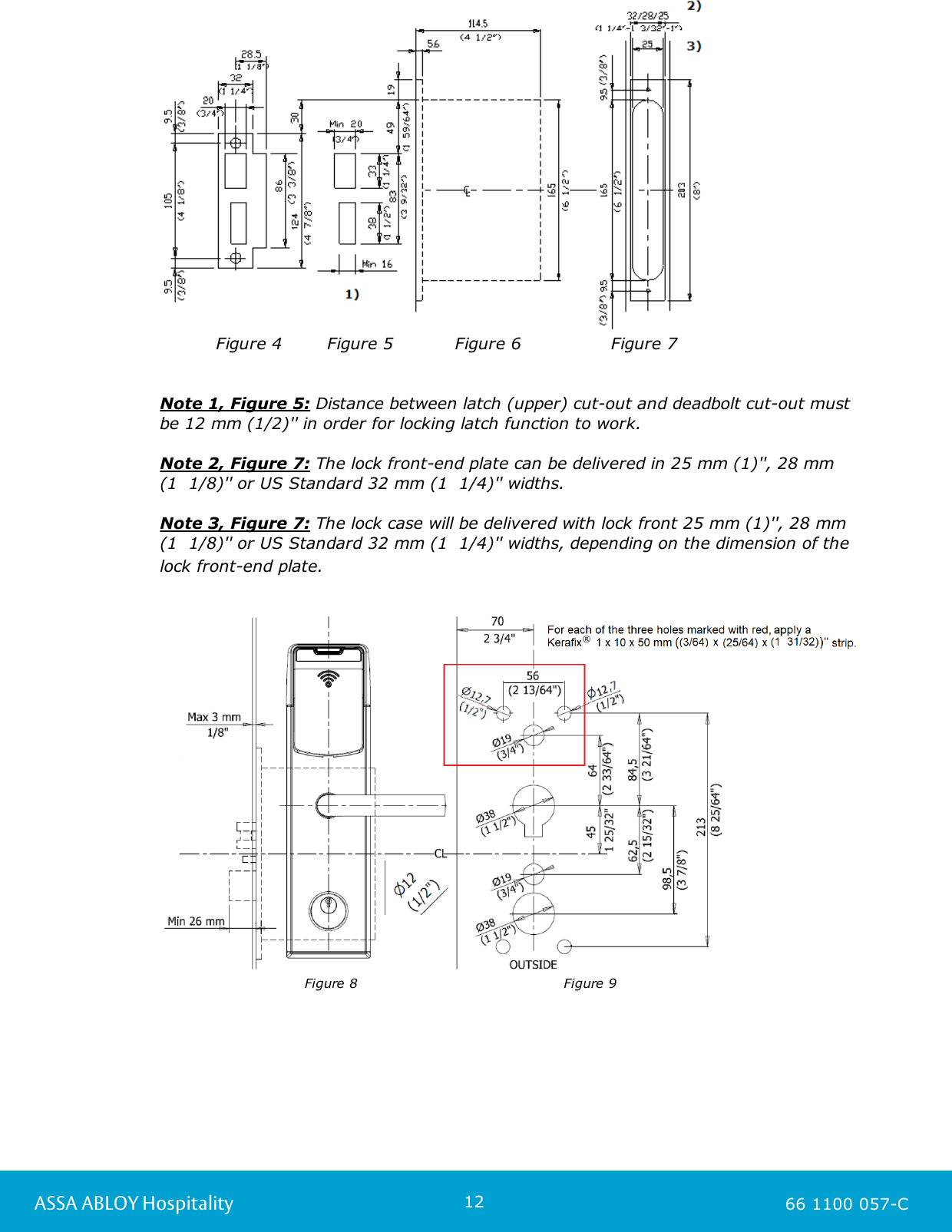
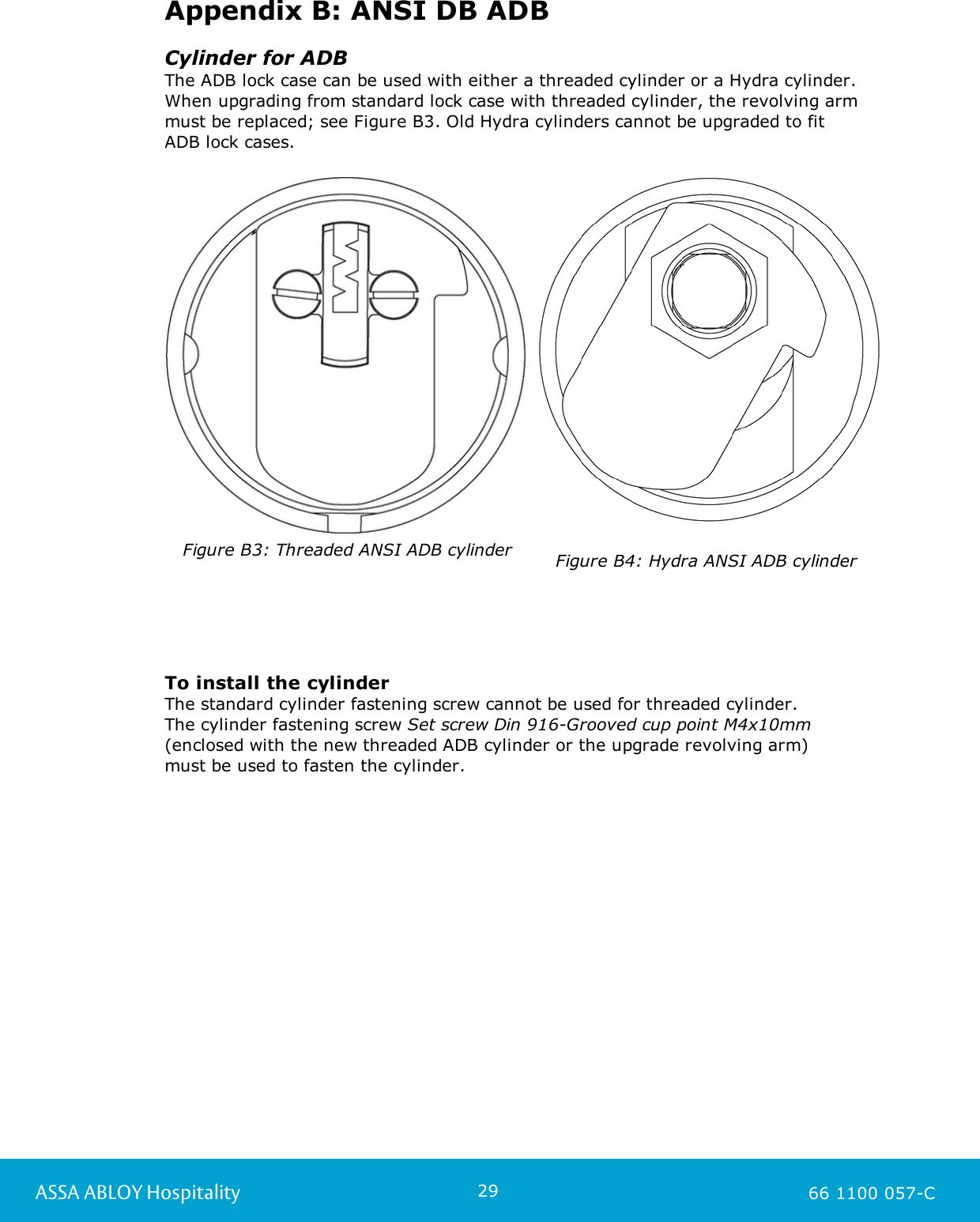
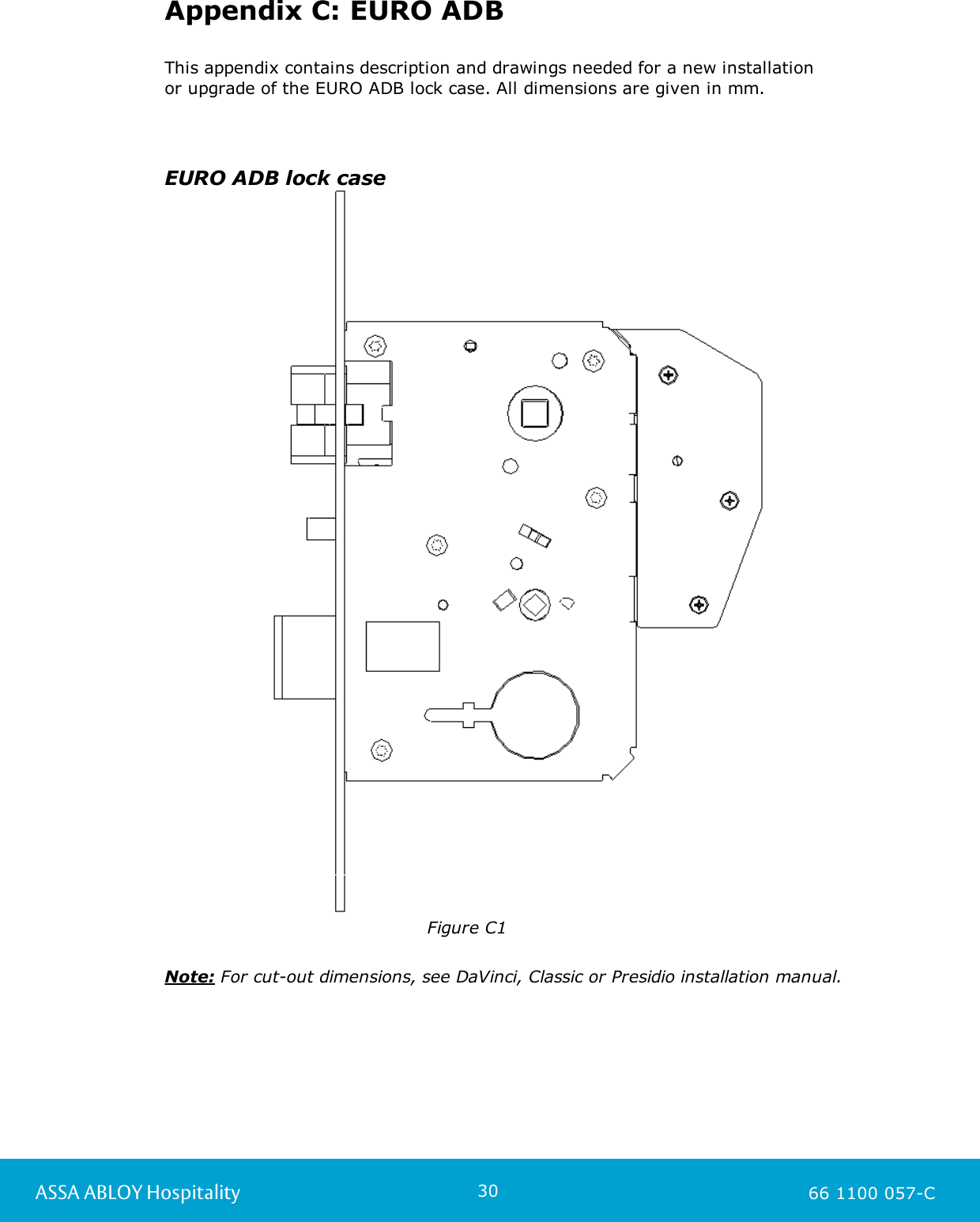
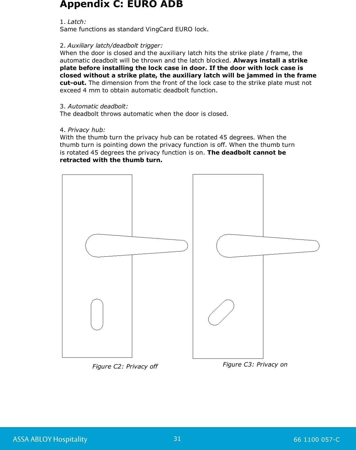
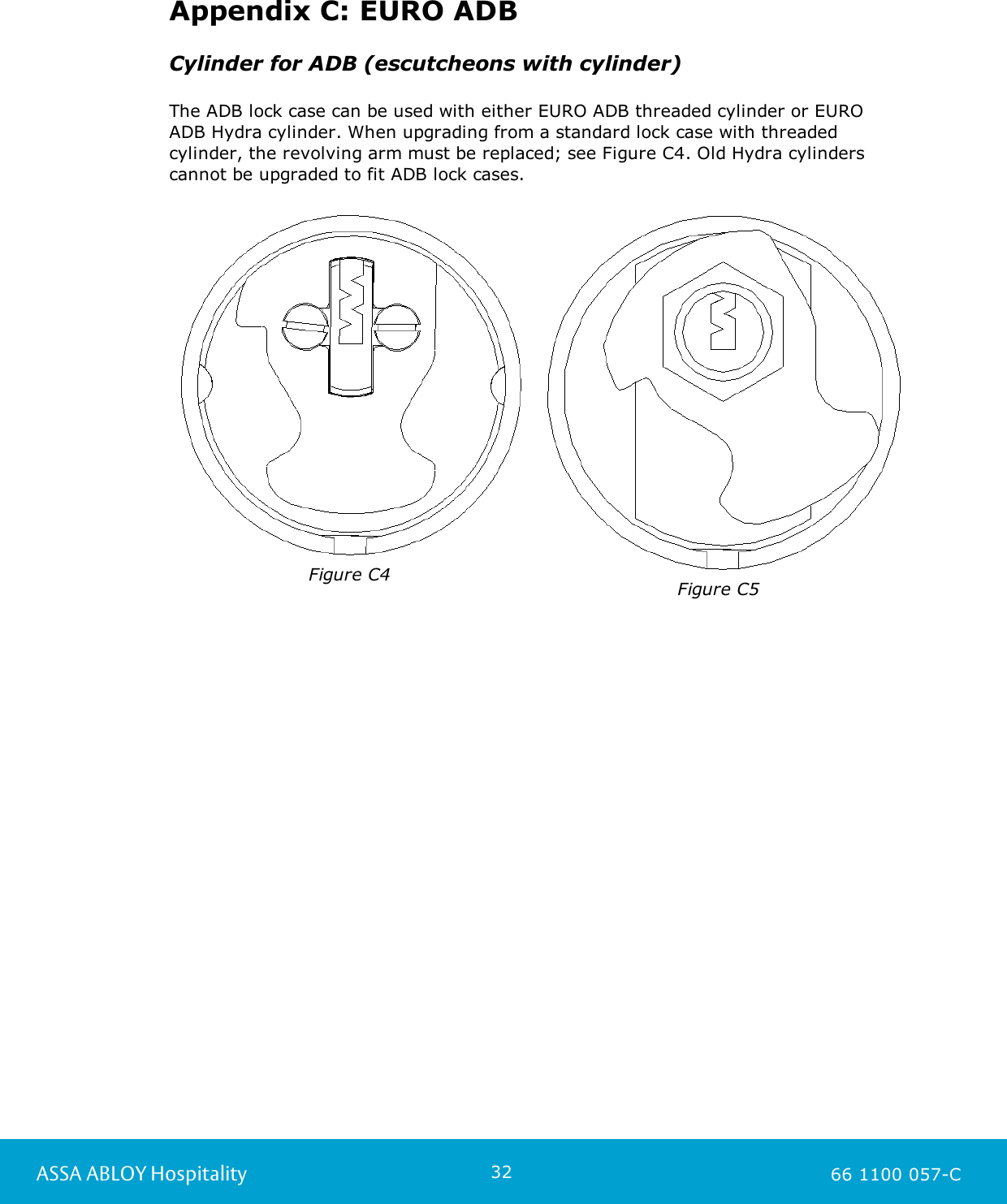
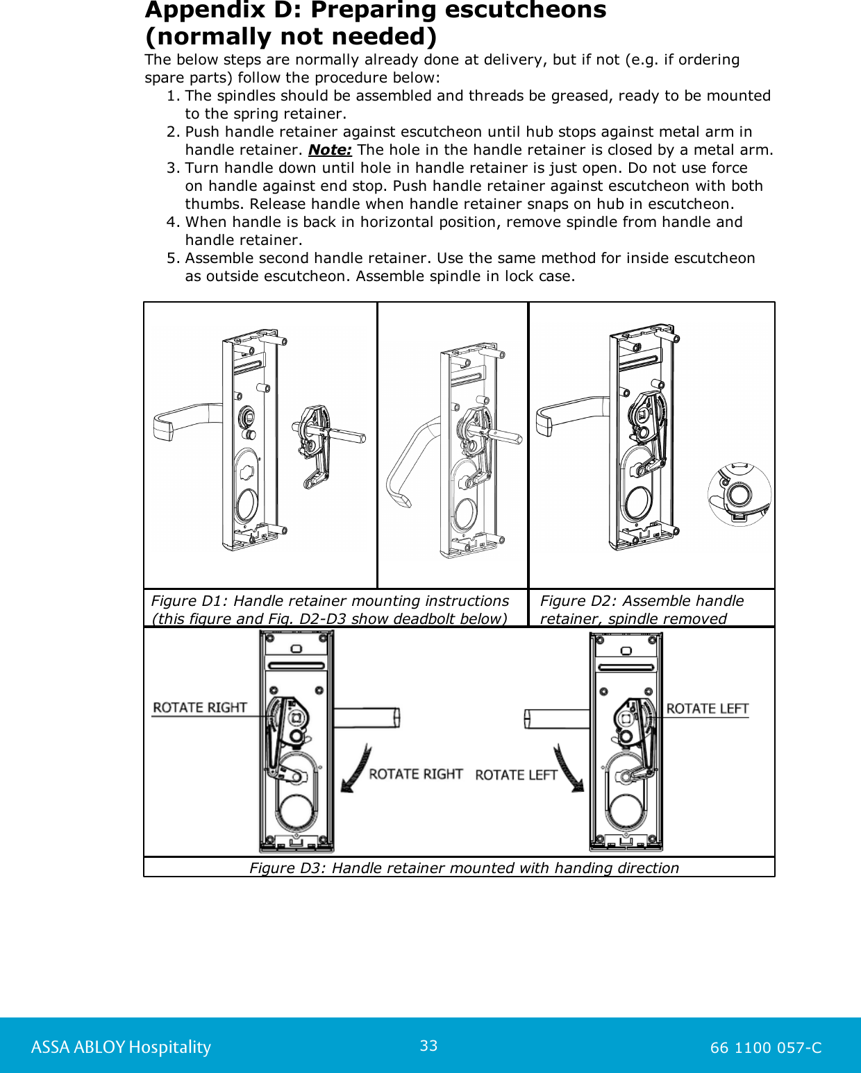
ASSALOY Global Solutions Norway AS LCU6351C1 RFID and BLE reader LCU 6351 User Manual Classic RFID

ASSA ABLOY Hospitality AS RFID and BLE reader LCU 6351 Classic RFID

User Manual

1ASSA ABLOY HospitalityTechnical ManualVingCard Classic RFID
2ASSA ABLOY HospitalityCopyrightsThe information in this document is subject to change at the sole discretion ofASSA ABLOY without notice.Any use, operation or repair in contravention of this document is at your own risk.ASSA ABLOY does not assume any responsibility for incidental or consequentialdamages arising from the use of this manual.All information and drawings in this document are the property of ASSA ABLOY.Unauthorized use and reproduction is prohibited.VingCard and Elsafe are registered trademarks of ASSA ABLOY.
3ASSA ABLOY HospitalityTable of contents.................................................................................................5 FCC/IC statements................................................................................................................. 5FCC statements for LCU ................................................................................................................. 5ISED (IC) statements for LCU ................................................................................................................. 7FCC statements for ZigBee endnode ................................................................................................................. 7ISED (IC) statements for ZigBee endnode ............................................................................................................................. 8OEM responsibilities .................................................................................................9 1. Introduction................................................................................................................. 91.1 Introduction to LCU 6351  .................................................................................................10 2. External dimension requirements................................................................................................................. 112.1 External strike dimensions ................................................................................................................. 132.2 Direction of opening ................................................................................................................. 132.3 Cut-outs .................................................................................................14 3. To install the lock................................................................................................................. 143.1 Exploded view  ............................................................................................................................. 143.1.1 RFID cut-out ............................................................................................................................. 153.1.2 Mag cut-out (for upgrade from mag) ............................................................................................................................. 163.1.3 RFID specific parts ............................................................................................................................. 163.1.4 Upgrade kits ............................................................................................................................. 173.1.5 Online by ZigBee ................................................................................................................. 173.2 To install the lock .................................................................................................21 4. Installation checklist................................................................................................................. 214.1 Installation check ................................................................................................................. 214.2 Operational check ................................................................................................................. 214.3 Security function check .................................................................................................22 5. Commissioning.................................................................................................23 6. Maintenance................................................................................................................. 236.1 To release the cover from the RFID module .................................................................................................23 7. Service functions.................................................................................................24 Appendix A: ANSI DA ADB................................................................................................................. 24ADB strike ............................................................................................................................. 25All frames (wooden and steel frames) ............................................................................................................................. 25Mortise ................................................................................................................. 26Cylinder for ADB ............................................................................................................................. 26To install the cylinder
4ASSA ABLOY Hospitality.................................................................................................27 Appendix B: ANSI DB ADB................................................................................................................. 27ADB strike ............................................................................................................................. 28All frames (wooden and steel frames) ............................................................................................................................. 28Mortise ................................................................................................................. 29Cylinder for ADB ............................................................................................................................. 29To install the cylinder .................................................................................................30 Appendix C: EURO ADB................................................................................................................. 30EURO ADB lock case ................................................................................................................. 32Cylinder for ADB (escutcheons with cylinder) .................................................................................................33 Appendix D: Preparing escutcheons (normallynot needed)
5ASSA ABLOY Hospitality 66 1100 057-CFCC/IC statementsFCC (Federal Communications Commission) statements for LCUThis device complies with Part 15 of the FCC Rules. Operation is subject to the following two conditions:    (1) this device may not cause harmful interference, and    (2) this device must accept any interference received, including interference that may cause undesired operation.Exposure statement:This portable device with its antenna complies with FCC RF exposure limits for general population /uncontrolled exposure. The antenna used for this device must not be co-located or operating inconjunction with any other antenna or transmitter. Use only the supplied antenna.  This equipment complies with FCC radiation exposure limits set forth for an uncontrolled environment.This transmitter must not be co-located or operating in conjunction with any other antennas or transmitters.Changes or modifications not expressly approved by the party responsible for compliance could void the user's authority to operate the equipment.Note: This equipment has been tested and found to comply with the limits for a Class B digital device, pursuant to part 15 of the FCC Rules. These limits are designed to provide reasonable protection against harmful interference in a residential installation. This equipment generates, uses and can radiate radio frequency energy and, if not installed and used in accordance with the instructions, may cause harmful interference to radio communications. However, there is no guarantee that interference will not occur in a particular installation. If this equipment does cause harmful interference to radio or television reception, which can be determined by turning the equipment off and on, the user is encouraged to try to correct the interference by one or more of the following measures:   - Reorient or relocate the receiving antenna.   - Increase the separation between the equipment and receiver.   - Connect the equipment into an outlet on a circuit different from that to which the       receiver is connected.   - Consult the dealer or an experienced radio/TV technician for help.The LCU must be labeled to say 'FCC ID: Y7V-LCU6351C1'. ISED (IC) statements for LCUThis device complies with Industry Canada licence-exempt RSS standard CAN ICES-3 (B)/NMB-3(B) B. Operation is subject to the following two conditions:     (1) this device may not cause interference, and     (2) this device must accept any interference, including interference that may cause undesired          operation of the device.Le présent appareil est conform aux CNR d’Industrie Canada applicables aux appareils radio exempts de licence. L’exploitation est autorisée aux deux conditions suivantes:    (1) l'appareil ne doit pas produire de brouillage, et    (2) l’utilisateur de l'appareil doit accepter tout brouillage radioélectrique subi, même si le brouillage est susceptible d’en compromettre le fonctionnement.
6ASSA ABLOY Hospitality 66 1100 057-CExposure statement:This portable device with its antenna complies with FCC RF exposure limits for general population /uncontrolled exposure. The antenna used for this device must not be co-located or operating inconjunction with any other antenna or transmitter. Use only the supplied antenna.  Under Industry Canada regulations, this radio transmitter may only operate using an antenna of a type and maximum (or lesser) gain approved for the transmitter by Industry Canada. To reduce potentialradio interference to other users, the antenna type and its gain should be so chosen that the equivalentisotropically radiated power (e.i.r.p.) is not more than that necessary for successful communication.This radio transmitter IC:9514A-LCU6351C1 has been approved by Industry Canada to operate with the antenna type listed below with the indicated maximum permissible gain and requiredantenna impedance. Antenna types not included in this list, having a gain greater than the maximum gain indicated for that type, are strictly prohibited for use with this device.Name/ModelGainImpedanceInverted F-antenna3.0 dBi50 ohmThe term "IC" before the equipment certification number only signifies that the Industry Canadatechnical specifications were met.Le terme "IC" devant le numéro de certification signifie seulement que les specifications techniquesIndustrie Canada ont été respectées.
7ASSA ABLOY Hospitality 66 1100 057-CFCC (Federal Communications Commission) statements for ZigBee endnodeThis device complies with Part 15 of the FCC Rules. Operation is subject to the following two conditions:    (1) this device may not cause harmful interference, and    (2) this device must accept any interference received, including interference that may cause undesired operation.Exposure statement:This portable device with its antenna complies with FCC RF exposure limits for general population /uncontrolled exposure. The antenna used for this device must not be co-located or operating inconjunction with any other antenna or transmitter. Use only the supplied antenna.  This equipment complies with FCC radiation exposure limits set forth for an uncontrolled environment.This transmitter must not be co-located or operating in conjunction with any other antennas or transmitters.Changes or modifications not expressly approved by the party responsible for compliance could void the user's authority to operate the equipment.Note: This equipment has been tested and found to comply with the limits for a Class B digital device, pursuant to part 15 of the FCC Rules. These limits are designed to provide reasonable protection against harmful interference in a residential installation. This equipment generates, uses and can radiate radio frequency energy and, if not installed and used in accordance with the instructions, may cause harmful interference to radio communications. However, there is no guarantee that interference will not occur in a particular installation. If this equipment does cause harmful interference to radio or television reception, which can be determined by turning the equipment off and on, the user is encouraged to try to correct the interference by one or more of the following measures:   - Reorient or relocate the receiving antenna.   - Increase the separation between the equipment and receiver.   - Connect the equipment into an outlet on a circuit different from that to which the       receiver is connected.   - Consult the dealer or an experienced radio/TV technician for help.The endnode must be labeled to say 'FCC ID: Y7V-683081150C1'.ISED (IC) statements for ZigBee endnodeThis device complies with Industry Canada licence-exempt RSS standard CAN ICES-3 (B)/NMB-3(B) B. Operation is subject to the following two conditions:     (1) this device may not cause interference, and     (2) this device must accept any interference, including interference that may cause undesired          operation of the device.Le présent appareil est conform aux CNR d’Industrie Canada applicables aux appareils radio exempts de licence. L’exploitation est autorisée aux deux conditions suivantes:    (1) l'appareil ne doit pas produire de brouillage, et    (2) l’utilisateur de l'appareil doit accepter tout brouillage radioélectrique subi, même si le brouillage est susceptible d’en compromettre le fonctionnement.Exposure statement:This portable device with its antenna complies with FCC RF exposure limits for general population /uncontrolled exposure. The antenna used for this device must not be co-located or operating inconjunction with any other antenna or transmitter. Use only the supplied antenna.  Under Industry Canada regulations, this radio transmitter may only operate using an antenna of a type and maximum (or lesser) gain approved for the transmitter by Industry Canada. To reduce potential
8ASSA ABLOY Hospitality 66 1100 057-Cradio interference to other users, the antenna type and its gain should be so chosen that the equivalentisotropically radiated power (e.i.r.p.) is not more than that necessary for successful communication.This radio transmitter IC9514A-683081150C1 has been approved by Industry Canada to operate with the antenna type listed below with the indicated maximum permissible gain and requiredantenna impedance. Antenna types not included in this list, having a gain greater than the maximum gain indicated for that type, are strictly prohibited for use with this device.Name/ModelGainImpedanceInverted F-antenna3.0 dBi50 ohmThe term "IC" before the equipment certification number only signifies that the Industry Canadatechnical specifications were met.Le terme "IC" devant le numéro de certification signifie seulement que les specifications techniquesIndustrie Canada ont été respectées.OEM responsibilitiesThe endnode module has been certified for integration into products only by OEM integrators under the following conditions: 1. The antenna must be installed such that a minimum separation distance of 20cm is maintainedbetween the radiator (antenna) and all persons at all times.2. The transmitter module must not be co-located or operating in conjunction with any otherantenna or transmitter. As long as the two conditions above are met, further transmitter testing will not be required. However, the OEM integrator is still responsible for testing their end-product for any additionalcompliance requirements required with these modules installed (e.g., digital device emissions, PC peripheral requirements, etc.).Important note: In the event that these conditions can not be met (for certain configurations or co-location with another transmitter), then Industry Canada certification is no longer considered validand the IC Certification Number can not be used on the final product. In these circumstances, the OEMintegrator will be responsible for re-evaluating the end products (including the transmitter) and obtaininga separate Industry Canada authorization.The OEM of the respective module must only use the approved antenna listed above, which have been certified with this module. The OEM integrator has to be aware not to provide information to the end user regarding how to install or remove this RF module or change RF related parameters in the user’s manual of the end products.
9ASSA ABLOY Hospitality 66 1100 057-C1. IntroductionThe VingCard Classic RFID lock is a standalone electronic lock with RFID (radiofrequency identification) technology, which can also be online by ZigBee 1. VingCardClassic RFID is compatible with the Visionline system. The lock has LED signals andcan also be configured for sound signals 2; see information about configuring thebeeper in section 1.1 below. Note: The VingCard Classic RFID lock can be used at new installations, or as an upgrade from VingCard Classic mag; in the latter case, only add the RFID reader by replacing the top cover. 1.1 Introduction to LCU 6351 LCU 6351 has the same dimensions and service contact as the previous LCU version (6334), but there are also some differences which are described below. Instead of having a separate BLE module, the LCU now includes the BLE radio.Initialization of BLE is however done in the same way as for previous LCU, i.e.mark 'Include BLE configuration data' under Initialize lock in Lock Service 3Gwhen initializing the lock/elevator controller/remote controller. As for previousLCU, if the signal strength should be changed from the default value 0 dBm and/or if seamless mode is applicable go to Configure lock in Lock Service 3G;choose 'Send configuration data (BLE)' and make the necessary settings for 'Tx power' and 'seamless mode'. See Quick reference guide Lock Service 3G for details about the Initialize lock and Configure lock operations. Minimum Lock Service 3G version is 2.3.0.2, which includes the below minimumfirmware versions:   - 3.17.37.4 (standard lock)   - 3.18.37.4 (elevator controller)   - 3.20.37.4 (remote controller)   - 3.40.37.4 (VingCard Allure standard lock) •  LCU 6351 can be configured to give sound signals: 1. Connect the service cable tothe lock/elevator controller/remote controller.2. Choose Configure lock in theleft pane of Lock Service 3G.3. In the upper drop-down-menu,choose 'Configure beeper'. 4. In the lower drop-down-menu,choose 'ON'. 5. Click the Set button.  1)  See User manual Online option for more details about the ZigBee network etc.2)  For information about different LED and sound signals which the lock can give,    see the appendix 'Lock LEDs and sounds and what they mean' in User manual Visionline.                                                                                                                                                                                           Continued on next page
10ASSA ABLOY Hospitality 66 1100 057-C• LCU 6351 can (in addition to the regular green/yellow/red LED signals) be   configured to show a flashing blue LED signal when the BLE radio is searching   for a mobile device to connect to: 1. Connect the service cable tothe lock/elevator controller/remote controller.2. Choose Configure lock in theleft pane of Lock Service 3G.3. In the upper drop-down-menu,choose 'Configure blue LED'.4. In the lower drop-down-menu,choose 'ON'. 5. Click the Set button.  2. External dimension requirementsBefore starting the installation, check the below dimensions (in mm/inches). Note 1: Allow at least 25.4 mm (1)'' in depth for deadbolt. Warning: When the deadbolt is thrown, the door cannot be opened with a metal key in case of emergency, if the cut-out is less than 25.4 mm (1)'' deep.Note 2: Gap between lock front-end and strike must not exceed 3 mm (1/8)''.Note 3: The lock front-end plate can be delivered in either 25 mm (1)'', 28 mm (1 1/8)'' or US Standard 32 mm (1 1/4)'' widths.Note 4: Minimum door thickness required is 34 mm (1 11/32)''. Spacer must be on doors that are less than 34 mm (1 11/32)'' thick.
11ASSA ABLOY Hospitality 66 1100 057-C     Figure 2: Lock case dimensions                                   Figure 3: Escutcheon dimensions       Note: CL is lock case center line.                                                                              Note: The cylinder hole is to be cut only for locks equipped with cylinder. Only one side of the door is to be mortised, i.e. the cut-out should not go through the entire door as the other cut-outs. 2.1 External strike dimensionsWooden frame: First install lock in door (see chapter 3), then position the strike(Figure 4) in frame so that top of the strike is 49 mm below top of  the outside front(19+30 mm).Steel frame/standard strike not used: First make sure that cut-out in doorconfirms to the dimensions in Figure 5. Then install lock in door and position the top of the lock case (step 1, chapter 3.3) in relation to the cut-out as shown in Figure 5.Pictures on next page: external strike dimensions (Figure 4) and cut-out dimensions(Figure 5) shown in relation to side view (Figure 6) and edge view (Figure 7) of mortise.
12ASSA ABLOY Hospitality 66 1100 057-C          Figure 4        Figure 5           Figure 6                Figure 7Note 1, Figure 5: Distance between latch (upper) cut-out and deadbolt cut-out mustbe 12 mm (1/2)'' in order for locking latch function to work. Note 2, Figure 7: The lock front-end plate can be delivered in 25 mm (1)'', 28 mm (1  1/8)'' or US Standard 32 mm (1  1/4)'' widths. Note 3, Figure 7: The lock case will be delivered with lock front 25 mm (1)'', 28 mm(1  1/8)'' or US Standard 32 mm (1  1/4)'' widths, depending on the dimension of thelock front-end plate.                           Figure 8                                           Figure 9
13ASSA ABLOY Hospitality 66 1100 057-CFigure 10               Figure 8: Position of lock in relation to door cut-out and frame. Figure 9: Cut-out dimensions to be made for escutcheon. Note: The hole with diameter 38 mm (1 1/2)''is only to be made if cylinder is applicable. For the cylinder hole, only one side of the door is to bemortised, i.e. the cut-out should not go through the entire door as the other cut-outs.Figure 10: Cross-section from top, showing mortises position if door is beveled. Note: If the door isbeveled, i.e. if edge is not at 90° to door, dimensions should be based on the shortest side (upper sidein Figure 10). 2.2 Direction of openingFigure 11LHLeft handleRHRight handleRHRRight handle, reversedLHRLeft handle, reversed                                            Table 12.3 Cut-outsFor new installations of VingCard Classic RFID, the cut-out drawings named 'Classic RFID' in Table 2 are applicable. For upgrade installations from VingCard Classic mag, the cut-out drawings named 'Classic mag' are applicable. Model/version nameCut-out drawingClassic RFID ANSI DA with cylinder AN-91Classic RFID ANSI DA without cylinder AN-92Classic RFID ANSI DB with cylinder AN-59Classic RFID ANSI DB without cylinderAN-89Classic RFID EURO with cylinderAN-60Classic RFID EURO without cylinder AN-90Classic mag ANSI DA (with and without cylinder) AN-112Classic mag ANSI DB (with and without cylinder)AN-110Classic mag EURO (with and without cylinder)AN-111                                                                                                         Table 2
14ASSA ABLOY Hospitality 66 1100 057-C3. To install the lock3.1 Exploded view3.1.1 RFID cut-outPosDescriptionPosDescriptionPosDescription1RFID module (see details in pos 1-7 of section 3.1.3)8Lock case15Battery holder2Escutcheon outside9Lock front screw16Classic battery lid, large3Cylinder assy10Lock front17LCA (lock case adapter) 6343 4, 12Handle retainer11Thumb turn spindle18Adapter for LCA5Outside spindle12See 419Escutcheon screw6Inside spindle 13Escutcheon inside7Safety pin14Bracket                         Table 3
15ASSA ABLOY Hospitality 66 1100 057-C3.1.2 Mag cut-out (for upgrade from Classic mag)Figure 13PosDescriptionPosDescriptionPosDescription1RFID module (see details in pos 1-7 of section 3.1.3)8Inside spindle 15Bracket2Escutcheon outside9Lock case16Battery holder3Cylinder assy10Lock front screw17Classic battery lid, large4, 13Handle retainer11Lock front18LCA (lock case adapter) 6343 5Upgrade plate12Thumb turn spindle19Adapter for LCA6Safety pin13  See 420Escutcheon screw7Outside spindle14Escutcheon inside                             Table 4
16ASSA ABLOY Hospitality 66 1100 057-C3.1.3 RFID specific componentsFigure 14: Note that the upgrade plate shown in pos 8 is for upgrades from Classic mag installations. PosDescriptionAMS part1Front cover assyPos 1-7 are sold as AMS part 'RFID module, assy'2Screw3Frame4LCU (lock controller unit)5Light pipe6Shield plate7Screw8Upgrade plate9LCA 6343Pos 9-10 are sold as AMS part 'LCA 6343 kit'10Adapter for LCA                                                                                                                                                       Table 53.1.4 Upgrade kitsNameDescriptionVingCard Classic 4G RFID upgrade kit (new projects); LCU & LCA VingCard Classic 3G RFID upgrade kit (AMS); LCU & LCA VingCard Classic 9V conversion cable kit Required in addition to upgrade kit for all 9Vinstallations; contains 9V conversion cable + battery cableLCUt1 conversion cableRequired in addition to upgrade kit & 9V conversioncable kit when upgrading from LCUt1 installations                                                                                                                                                        Table 6
17ASSA ABLOY Hospitality 66 1100 057-C3.1.5 Online by ZigBeeA Classic RFID lock can be online by ZigBee. In this case, a ZigBee endnode is mounted in the bracket as shown in Figure 15. Figure 15 3.2 To install the lockThe bold numbers in brackets refer to the exploded views. For upgrade installations from Classic mag, remove the top cover from the outside escutcheon and then start the installation from step 19 below. Note: Gothic style escutcheon is not recommended for VingCard Classic RFID upgrades.Note: For a reliable operation:No parts should be lubricated, except for spindle threadsWhen cleaning escutcheons, use soft moist cloth without detergentIf Hydra cylinder is in use:Thread the security clip onto the lock case from bottom side, at 45° and press it upwards so the groove is aligned to the cable cover mounting screw.1. Position the lock case (RFID:8; mag:9) into the door edge and fasten it with two lock front screws (RFID:9; mag:10).    Note: Position the cable in the door before inserting the lock case.2. Normally, the handle retainers are at delivery mounted in the outside and inside escutcheons respectively. If they are not (e.g. if spare parts have been ordered), the escutcheons must be prepared according to Appendix E.3. Mount the spindle (RFID:5+6; mag:7+8) in the lock case from the outside. The safety pin (RFID:7; mag:6) is holding the handle spindle in correct position.Push the pin into the hole through the inside spindle. If plastic ring is used,
18ASSA ABLOY Hospitality 66 1100 057-Cpush the plastic ring onto the inside spindle, making sure that the ring fits into its groove. 4. Position the outside escutcheon onto the spindle.5. Insert the thumb turn spindle (RFID:11; mag:12) through the lock case until it stops against the outside escutcheon.6. Mount the inside escutcheon (RFID:13; mag:14) including handle retainer asfollows: set the thumb turn in its vertical position, while the deadbolt is retracted.7. Before mounting the inside escutcheon on the door, make sure that:    - The outside spindle and inside spindle fit correctly in their positions; make       sure that there is a 3/4 turn between them (normally fixed already at delivery).    - Inside and outside handle retainers (RFID:4 and 12; mag:4 and 13) are       correctly mounted according to door handing; see Appendix E.    - The cable to the battery is placed correctly through the notch on top of        the escutcheon.    Leave the connectors accessible on the inside of the door.8. Connect the cable from the lock case to the LCA (RFID:17; mag:18).Important: Connectors should mount easily; avoid using force. If condensation can occur (as is likely in hollow steel doors), the contacts should be filled with silicone grease.9. Fasten the outside escutcheon (2) and inside escutcheon respectively with fourescutcheon screws (RFID:19; mag:20) as shown, but do not tighten them at this point. Important: The protruding parts must fit correctly. Any bending ormisalignment may cause malfunction. Important: For lock without cylinder, never close door before lock is programmed and working with card operation.If your lock is equipped with standard cylinder (3), proceed to step 11.Hydra cylinder is used along with clips.10.Prepare the cylinder as follow:      - Insert an operational key and turn the cylinder so the cylinder arm is in        6 o’clock position.     - Insert the cylinder into the lock case and position the cylinder so it is flush        to the outside escutcheon.      - Fix the cylinder in place with the fixing–screw tool kit as follows:a) Use the L–shaped Allen key to lock the headless fixing screw to the     T–shaped tool as illustration in the box shows.b) Using the T–tool, screw the fixing–screw in place as shown to fix the cylinder     in place. When tighten the screw, put pressure on the Allen wrench, not the     T-handle, to avoid over-tightening. Make sure that the cylinder fixing–screw     is tightened in the cylinder.c) Release the T–tool from fixing–screw by holding the T–tool rigid while
19ASSA ABLOY Hospitality 66 1100 057-Cturning the Allen key counter-clockwise until the tool is released, then unscrewthe tool.If your lock is equipped with Hydra cylinder, proceed to step 12.11.Install the cylinder (3) and fasten it with the cylinder set screw using an Allenwrench. When using a standard cylinder with ADB lock case, use the optional short screw as described in the applicable Appendix A (ANSI DA), Appendix B(ANSI DB) or Appendix C (EURO). 12.Important: Check all functions for smooth operation before final tightening of the escutcheon screws. Throw the deadbolt with thumb turn and retract the latchand deadbolt by depressing the inside handle. When installing an ADB lock casethe deadbolt is thrown by pushing the trigger, and retracted by depressing theinside handle.13.Install the battery pack by connecting the battery cable to the battery. Note: Yellow light should flash once after battery is connected.14.If the battery lid is in metal, the battery cup (not shown in the exploded views  in section 3.1) must be threaded upon the battery before connecting the battery  cable (only for 9V / 6 batteries). Note: If this battery lid is used, it is not possible  to have the lock online by ZigBee. 15.Fasten the lock front (RFID:10; mag:11) with lock front screws (RFID:9;mag:10). Make sure that the anti-friction latch comes all the way out.16.Tighten the four escutcheon screws (RFID:19; mag:20), ensuring that the inside  and outside escutcheons are aligned to each other. 17.The RFID module is normally assembled with the outside escutcheon at delivery,but if it is not (e.g. if the RFID module has been ordered as a spare part), snap theRFID module (1) in place on top of the outside escutcheon and fasten it with thescrew (pos 2 in section 3.1.3) in the front; see Figure 16. An additional mountinghole is available in the top left corner of the LCU (lock controller unit), if this isneeded. Note: For upgrades, the LCU must be removed and the upgrade plate(mag:5) be mounted; see details in step 20. Figure 16
20ASSA ABLOY Hospitality 66 1100 057-C18.The cable is normally at delivery pulled through the cable leader as shown inFigure 17, but if it is not (e.g. if the RFID module has been ordered as a sparepart), pull the cable through the cable leader. Note: Be aware of sharp edges on door and escutcheon which can damage the RFID cable upon mounting.Figure 1719.When upgrading an existing ASSA ABLOY Hospitality installation with LCU (lockcontroller unit) or RM/CM (reader module/control module), the upgrade plate mustbe installed. This is a precaution which is required due to already existing holes in the door. Use the old mounting screws from the LCU/RM to fasten the upgradeplate as shown in Figure 18. Additional fire protection material must also be placedin the location of the removed LCU/RM. Figure 18    Note: At new installations with RFID Classic cut-outs, the upgrade plate is notneeded. Note: When upgrading a non-VingCard lock to VingCard Classic RFID, a cover plate with dimensions according to the guidelines given in Application Note 93(AN-93) will replace the upgrading plate. 20.The lock case adapter (LCA) (RFID:17; mag:18) is normally delivered in place in the adapter for LCA (RFID:18; mag:19), but if this is not the case (e.g. if the LCA has been ordered as a spare part), snap the LCA in place and fasten theconnectors. 21.Connect the battery cable, the lock case cable and the cable from the LCU  before the inside unit is snapped in place on the inside escutcheon.22.Install the battery lid (RFID:16; mag:17) by using the lid opener.
21ASSA ABLOY Hospitality 66 1100 057-C4. Installation checklist4.1 Installation check1. Mortise of the lock: The front–end (including the lock case cover plate) should be flush with the door edge.2. Installation of cylinder: The cylinder should be flush with the escutcheon andproperly fixed.3. Installation of escutcheon: The escutcheon should be aligned vertical to the door edge and be tightened firmly.4. Installation of strike: The depth in the frame must be sufficient, min 1” (25.4 mm),to accommodate the full thrown deadbolt.4.2 Operational check1. Outside and inside handle: Handles must return to horizontal position after being depressed (outside handle can only be depressed slightly as the lock is in locked position).2. Thumb turn: The thumb turn must throw and retract the deadbolt freely.    Note: When installing ADB lock case the thumb turn cannot retract deadbolt.     The trigger will throw the deadbolt if depressed.3. Cylinder: When using an emergency key (EMK), latch and deadbolt must freely operate.4. Latch and deadbolt: When the deadbolt has been retracted by the thumb turn and the inside handle is fully depressed, deadbolt and latch should be flush withthe lock case cover plate.5. Electronics  Note: If there is no cylinder available, it’s important to check that theelectronics works before closing the door. The lock is programmed by showing theconstruction card to the lock twice. On first presentation you will see an orangeLED and then on the second a green LED and you will be able to turn the handle to retract the door latch.4.3 Security function check1. Dead latch function: When depressing the locking latch, the latch should beblocked. Make sure the latch is not snagged by the strike when the door is closed.2. Panic release function: When the door is closed and the deadbolt is thrown, depress the inside handle. The deadbolt and the latch must be retracted.
22ASSA ABLOY Hospitality 66 1100 057-C5. CommissioningWhen the locks have been mounted and connected according to the previouschapters, the following steps should be performed:1. Make sure that each lock has got the correct firmware version, i.e. latest availableversion of lock firmware for Visionline. The version is read out with the service PCand the software Lock Service 3G 1, which is also used for uploading the correctfirmware to the lock if needed 2. 2. Each lock is set up as a door in Visionline 3. 3. Download data from the Visionline server to Lock Service 3G 4. 4. Set system ID in each lock 5.5. Initialize each lock with room number and also with parameters set up in Visionlinefor each concerned lock 6 (if applicable with 'Include BLE configuration data'marked). Note: The initialization will also set the time in the lock. 6. If applicable, make configurations for the lock (e.g. regarding beeper and/or blue LED) 7. 7. If ZigBee is applicable, this requires that the Online option has been set inVisionline and that the ZigBee network has been set up 8. 1) See the section Parameters in Quick reference guide Lock Service 3G for details. 2) See the section Upload firmware in Quick reference guide Lock Service 3G for details. 3) See the section To set up a door in Setup manual Visionline for details.  4) See the section Download data from server in Quick reference guide Lock Service 3G for details.5) See the section Set system ID in lock in Quick reference guide Lock Service 3G for details. 6) The initialization can either be done with a service cable and Lock Service 3G (see the section     Initialize lock in Quick reference guide Lock Service 3G for details), or with an initiation card     issued in Visionline (see the section Initiation card in Setup manual Visionline). 7) See the section Configure lock in Quick reference guide Lock Service 3G for details. 8) See User manual Online option for details.
23ASSA ABLOY Hospitality 66 1100 057-C6. Maintenance6.1 To release the cover from the RFID moduleIf the LCU contact needs to be reached, e.g. for firmware upgrade, the cover(front cover assy in section 3.1.3) is demounted according to below:1. Press the two wings on top of the cover (marked with arrows in the left picturebelow), and at the same time pull the cover according to the right picture below.Figure 19Figure 207. Service functionsFunctionRead moreRead-outFor information about read-out with the service PC and the software LockService 3G, see Quick reference guide Lock Service 3G. For information about read-out with a read-out card or read-out cardadvanced, see User manual Visionline. Firmware upgradeFor information about firmware upgrade with the service PC and Lock Service3G, see Quick reference guide Lock Service 3G. Cold resetFor information about cold reset, see Quick reference guide Lock Service 3G.
24ASSA ABLOY Hospitality 66 1100 057-CAppendix A: ANSI DA ADBThis appendix contains description and drawings needed for a new installation orupgrade of the ANSI DA ADB lock case. All dimensions are given in mm and inches.ADB strikeWhen doing either a fresh install or an upgrade to ANSI DA ADB lock case, the external strike plate must be installed as shown in Figure A1.Figure A1Important: When installing an ADB lock case, the ADB strike plate with curved lipmust always be used (door handing L and R).Door handingStrike LStrike RLH (Rx)XRHR (Ro)XRH (Lx)XLHR (Lo)X                              Table A1
25ASSA ABLOY Hospitality 66 1100 057-CAppendix A: ANSI DA ADBAll frames (wooden and steel frames)First install the lock in the door as shown in section 3.3. Place the ADB strike in theframe as shown in Figure A1, 49mm below the top of the lock front (30mm + 19mm).MortiseIf the frame is mortised for a standard ANSI strike, the frame must be modified asshown in Figure A2.Figure A2
26ASSA ABLOY Hospitality 66 1100 057-CAppendix A: ANSI DA ADBCylinder for ADB (escutcheons with cylinder)The ADB lock case can be used with either a threaded cylinder or a Hydra cylinder.When upgrading from standard lock case with threaded cylinder, the revolving armmust be replaced; see Figure A3. Old Hydra cylinders cannot be upgraded to fit ADB lock cases.Figure A3: Threaded ANSI ADB cylinderFigure A4: Hydra ANSI ADB cylinderTo install the cylinderThe standard cylinder fastening screw cannot be used for threaded cylinder. The cylinder fastening screw Set screw Din 916-Grooved cup point M4x10mm(enclosed with the new threaded ADB cylinder or the upgrade revolving arm) must be used to fasten the cylinder.
27ASSA ABLOY Hospitality 66 1100 057-CAppendix B: ANSI DB ADBThis appendix contains description and drawings needed for a new installation orupgrade of the ANSI DB ADB lock case. All dimensions are given in mm and inches.ADB strikeWhen doing either a fresh install or an upgrade to ANSI DB ADB lock case, the external strike plate must be installed as shown in Figure B1.Figure B1Important: When installing an ADB lock case, the ADB strike plate with curved lipmust always be used (door handing L and R).Door handingStrike LStrike RLH (Rx)XRHR (Ro)XRH (Lx)XLHR (Lo)X                              Table B1
28ASSA ABLOY Hospitality 66 1100 057-CAppendix B: ANSI DB ADBAll frames (wooden and steel frames)First install the lock in the door as shown in section 3.3. Place the ADB strike in theframe as shown in Figure B1, 49mm below the top of the lock front (30mm + 19mm).MortiseIf the frame is mortised for a standard ANSI strike, the frame must be modified asshown in Figure B2.Figure B2
29ASSA ABLOY Hospitality 66 1100 057-CAppendix B: ANSI DB ADBCylinder for ADBThe ADB lock case can be used with either a threaded cylinder or a Hydra cylinder.When upgrading from standard lock case with threaded cylinder, the revolving armmust be replaced; see Figure B3. Old Hydra cylinders cannot be upgraded to fit ADB lock cases.Figure B3: Threaded ANSI ADB cylinderFigure B4: Hydra ANSI ADB cylinderTo install the cylinderThe standard cylinder fastening screw cannot be used for threaded cylinder. The cylinder fastening screw Set screw Din 916-Grooved cup point M4x10mm(enclosed with the new threaded ADB cylinder or the upgrade revolving arm) must be used to fasten the cylinder.
30ASSA ABLOY Hospitality 66 1100 057-CAppendix C: EURO ADBThis appendix contains description and drawings needed for a new installation or upgrade of the EURO ADB lock case. All dimensions are given in mm.EURO ADB lock caseFigure C1Note: For cut-out dimensions, see DaVinci, Classic or Presidio installation manual.
31ASSA ABLOY Hospitality 66 1100 057-CAppendix C: EURO ADB1. Latch: Same functions as standard VingCard EURO lock. 2. Auxiliary latch/deadbolt trigger: When the door is closed and the auxiliary latch hits the strike plate / frame, theautomatic deadbolt will be thrown and the latch blocked. Always install a strikeplate before installing the lock case in door. If the door with lock case isclosed without a strike plate, the auxiliary latch will be jammed in the framecut-out. The dimension from the front of the lock case to the strike plate must notexceed 4 mm to obtain automatic deadbolt function. 3. Automatic deadbolt:The deadbolt throws automatic when the door is closed.4. Privacy hub:With the thumb turn the privacy hub can be rotated 45 degrees. When the thumb turn is pointing down the privacy function is off. When the thumb turn is rotated 45 degrees the privacy function is on. The deadbolt cannot be retracted with the thumb turn.Figure C2: Privacy offFigure C3: Privacy on
32ASSA ABLOY Hospitality 66 1100 057-CAppendix C: EURO ADBCylinder for ADB (escutcheons with cylinder)The ADB lock case can be used with either EURO ADB threaded cylinder or EURO ADB Hydra cylinder. When upgrading from a standard lock case with threadedcylinder, the revolving arm must be replaced; see Figure C4. Old Hydra cylinderscannot be upgraded to fit ADB lock cases.   Figure C4Figure C5
33ASSA ABLOY Hospitality 66 1100 057-CAppendix D: Preparing escutcheons (normally not needed)The below steps are normally already done at delivery, but if not (e.g. if orderingspare parts) follow the procedure below: 1. The spindles should be assembled and threads be greased, ready to be mountedto the spring retainer. 2. Push handle retainer against escutcheon until hub stops against metal arm inhandle retainer. Note: The hole in the handle retainer is closed by a metal arm.3. Turn handle down until hole in handle retainer is just open. Do not use force on handle against end stop. Push handle retainer against escutcheon with boththumbs. Release handle when handle retainer snaps on hub in escutcheon. 4. When handle is back in horizontal position, remove spindle from handle and handle retainer.5. Assemble second handle retainer. Use the same method for inside escutcheon as outside escutcheon. Assemble spindle in lock case. Figure D1: Handle retainer mounting instructions (this figure and Fig. D2-D3 show deadbolt below)   Figure D2: Assemble handle   retainer, spindle removed    Figure D3: Handle retainer mounted with handing direction
34ASSA ABLOY Hospitalitywww.assaabloyhospitality.com

Navigation menu