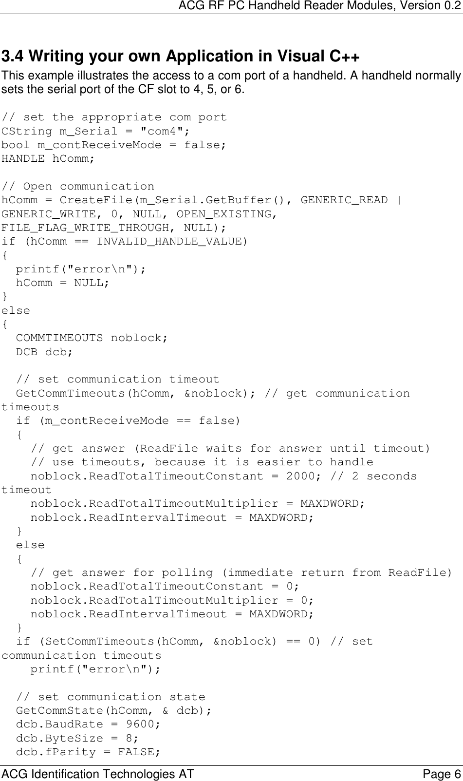
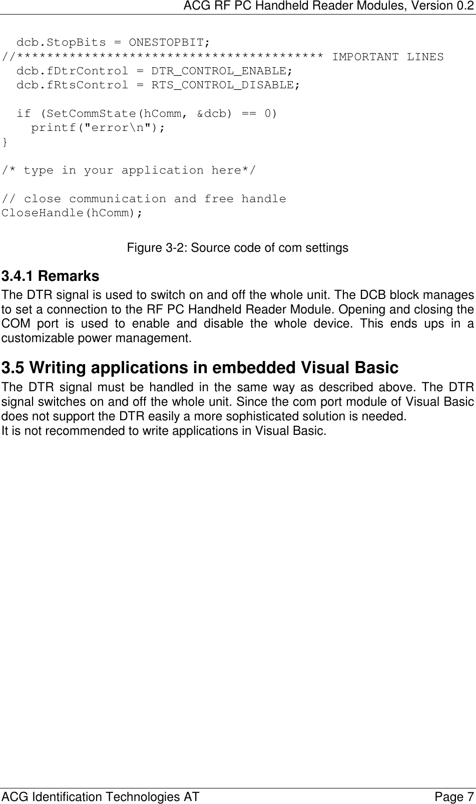
ASSALOY Identification Technologies H6160BA Inductive Tag Reader User Manual
ASSA ABLOY Identification Technologies GmbH Inductive Tag Reader Users Manual
UserManual.wiki
>
ASSALOY Identification Technologies
>
H6160BA User Manual
Users Manual
Navigation menu
Upload a User Manual
Namespaces
Wiki Guide
HTML
PDF
Info
Views
User Manual
Discussion / Help
Navigation
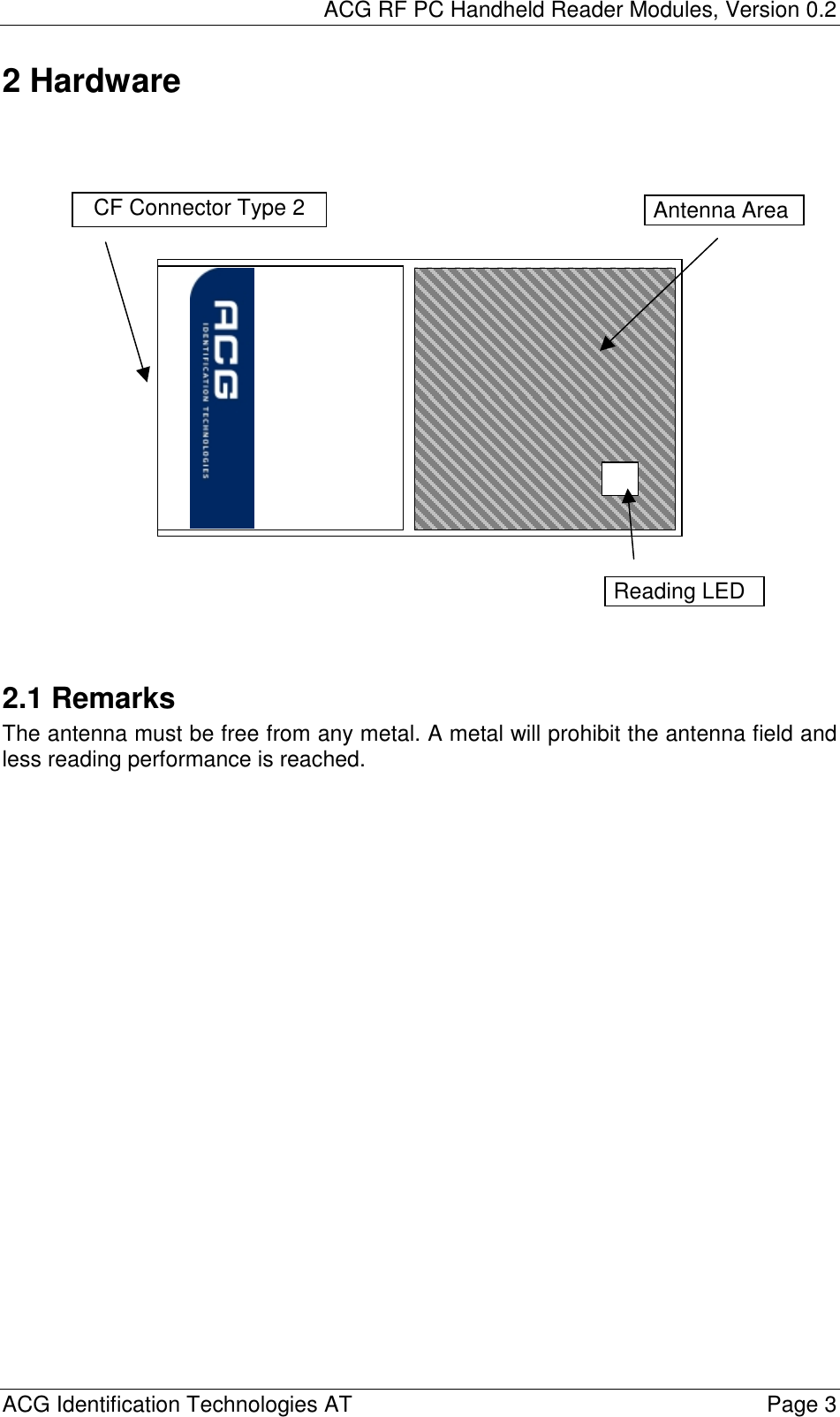
![ACG RF PC Handheld Reader Modules, Version 0.2 ACG Identification Technologies AT Page 2 1 Scope The ACG 13.56 MHz RF PC Handheld Reader Module is a read write device that supports a broad range of transponders. It is designed to communicate with ISO15693, Tagit® and Icode®. With its integrated antenna and compact flash type 2 connector it is ready to use and easily connected into a handheld, laptop or tablet PC. The ACG ISO 14443 AB RF PC Handheld Reader supports Mifare Standard, Ultralight, ProX and DESFire tags. Its open structure of the transfer command set allows to communicate with a broad range of dual processor cards based on ISO 14443-4. Using a PCMCIA adapter it can be connected into a PCMCIA slot type 2. The unit includes a device driver for Windows 98, Me, 2000, NT Service Pack 4 and XP. This document describes the installation of the device driver and an easy access to the RF PC Handheld Reader Modules. The command set of the ACG 13.56 MHz RF PC Handheld Reader Module is described in detail in the document ACG 13.56 MHz Multitag Reader Module [1] and is not listed here. The command set of the ACG ISO 14443 AB RF PC Handheld Reader Module is described in ACG Mifare Family Reader Module documentation [2]. WARNING: Some PCMCIA adapters of handheld PCs are not compatible with the RF PC Handheld Readers. Extensive testing of used hardware is needed prior to any design-ins. No problems have been reported using Compact Flash adapters so far. This product may be bundled with third party software. The warranty provisions of the document do not apply to such third party software. If a separate end user license agreement has been provided for such third party software, use of that software will be governed by that agreement. WARRANTY THIS DEVICE COMPLIES WITH PART 15 OF THE FCC RULES. OPERATION IS SUBJECT TO THE FOLLOWING TWO CONDITIONS: (1) THIS DEVICE MAY NOT CAUSE HARMFUL INTERFERENCE, AND (2) THIS DEVICE MUST ACCEPT ANY INTERFERENCE RECEIVED, INCLUDING INTERFERENCE THAT MAY CAUSE UNDESIRED OPERATION. CAUTION: ANY CHANGES OR MODIFICATIONS NOT EXPRESSLY APPROVED BY THE PARTY RESPONSIBLE FOR COMPLIANCE COULD VOID THE USER’S AUTHORITY TO OPERATE THE EQUIPMENT.](https://usermanual.wiki/ASSALOY-Identification-Technologies/H6160BA/User-Guide-367198-Page-3.png)
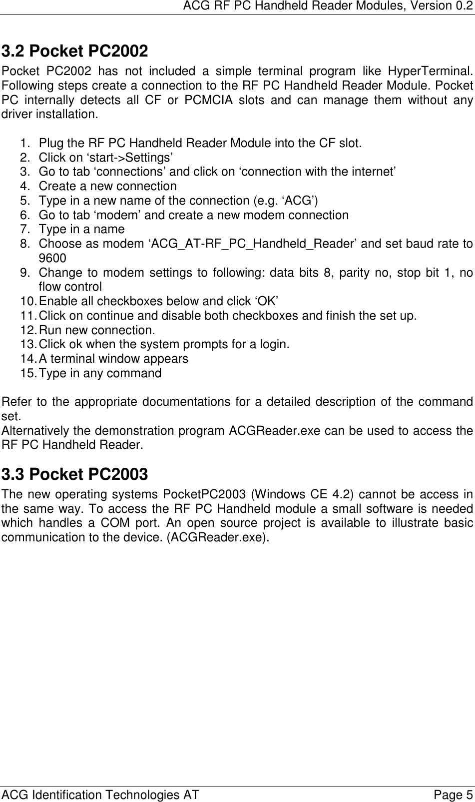
![ACG RF PC Handheld Reader Modules, Version 0.2 ACG Identification Technologies AT Page 4 3 Software The ACG 13.56 MHz RF PC Handheld Reader Module is compatible to the ACG 13.56 MHz Multitag Reader Module H102022 [1]. The ACG ISO 14443 AB RF PC Handheld Reader Module is fully compatible to the ACG ISO 14443 AB Reader Module H102024 [2]. 3.1 Installation of the PCMCIA driver The RF PC Handheld Reader Module can be connected to a laptop or a PC using an adapter of PCMCIA type 2. 1. First time the module is plugged into the slot the user will be prompt to install the correct driver. 2. Follow the instructions on the screen. 3. Click on ‘Have Disk…’ to define the driver location manually. 4. go to folder ‘RCPCHandheldACG’ and double-click on ‘RFPCHandheldACG.inf’. 5. Finish the installation The system has loaded all necessary drivers of the RF PC Handheld Reader Module. Using a terminal program (e.g. HyperTerminal) the module can be accessed by opening the appropriate COM port. 3.1.1 HyperTerminal settings First you have to connect to the correct COM port. Normally the system sets up COM 4 or COM 5 for the PCMCIA slots. The baud rate depends on the startup settings of the reader device. Default is 9600 baud. Description 8 data bits No parity bit 1 stop bit No flow control Figure 3-1: Communication settings](https://usermanual.wiki/ASSALOY-Identification-Technologies/H6160BA/User-Guide-367198-Page-5.png)
![ACG RF PC Handheld Reader Modules, Version 0.2 ACG Identification Technologies AT Page 8 4 Revision History Date Revision number 9/18/2003 0.1 10/7/2003 0.2 10/10/2003 0.3 5 References [1] ACG 13.56 MHz Multitag Reader Module Documentation, H102022 [2] ACG ISO 14443 AB Reader Module Documentation, H102024 [3] http://www.acg.de [4] http://www.microsoft.com](https://usermanual.wiki/ASSALOY-Identification-Technologies/H6160BA/User-Guide-367198-Page-9.png)