ASSALOY Identification Technologies RDHC-0202N0-0X Inductive Tag Reader Module User Manual HF Multi ISO V1 0 06
ASSA ABLOY Identification Technologies GmbH Inductive Tag Reader Module HF Multi ISO V1 0 06
UserManual.wiki
>
ASSALOY Identification Technologies
>
RDHC 0202N0 0X User Manual
Users Manual
Navigation menu
Upload a User Manual
Namespaces
Wiki Guide
HTML
PDF
Info
Views
User Manual
Discussion / Help
Navigation
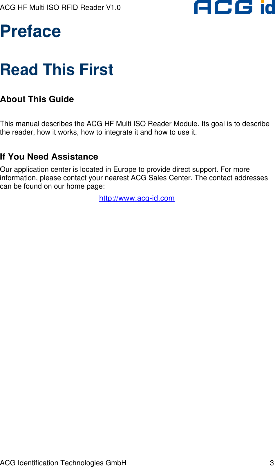
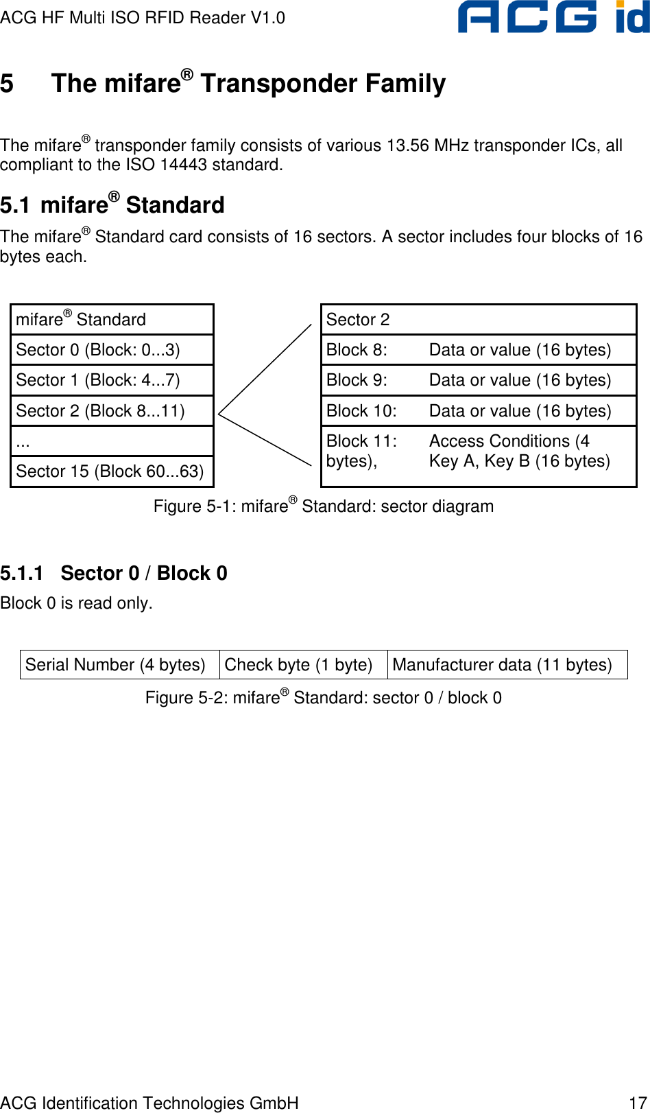
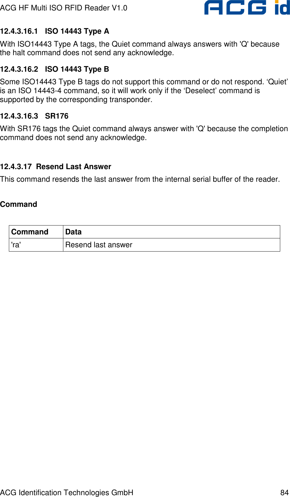
![ACG HF Multi ISO RFID Reader V1.0 ACG Identification Technologies GmbH 13 3.2 Abbreviations Abbreviation Description AID Application ID ASCII American Standard Code for Information Interchange ATR Answer to Reset ATS Answer to Select AFI Application Family Identifier block For the mifare® Standard one block contains 16 bytes CBC Cipher Block Chaining CID Card Identifier (logical card address, ISO 14443-4) CRC Cyclic Redundancy Check DES Data Encryption Standard, for more details about DES refer to [3]. DSFID Data storage format identifier EDC Error Detection Code EGT Extra Guard Time EOF End of Frame ETU Elementary time unit Hex / xxh Value in Hexadecimal notation I-block Information block KTT Key Transfer Transponder LSB Least Significant Bit or Byte MSB Most Significant Bit or Byte NAD Node Address (ISO 14443-4) OSI Open System Interconnection OTP One time programmable PCB Protocol Control Byte (ISO 14443-4) PCON Protocol Configuration byte of the reader PPS Protocol and Parameter Selection RATS Request for Answer to Select R-block Receive ready block REQA Request ISO Type A REQB Request ISO Type B RFU Reserved for Future Use](https://usermanual.wiki/ASSALOY-Identification-Technologies/RDHC-0202N0-0X/User-Guide-702035-Page-14.png)

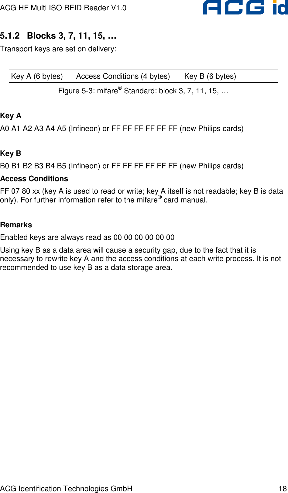
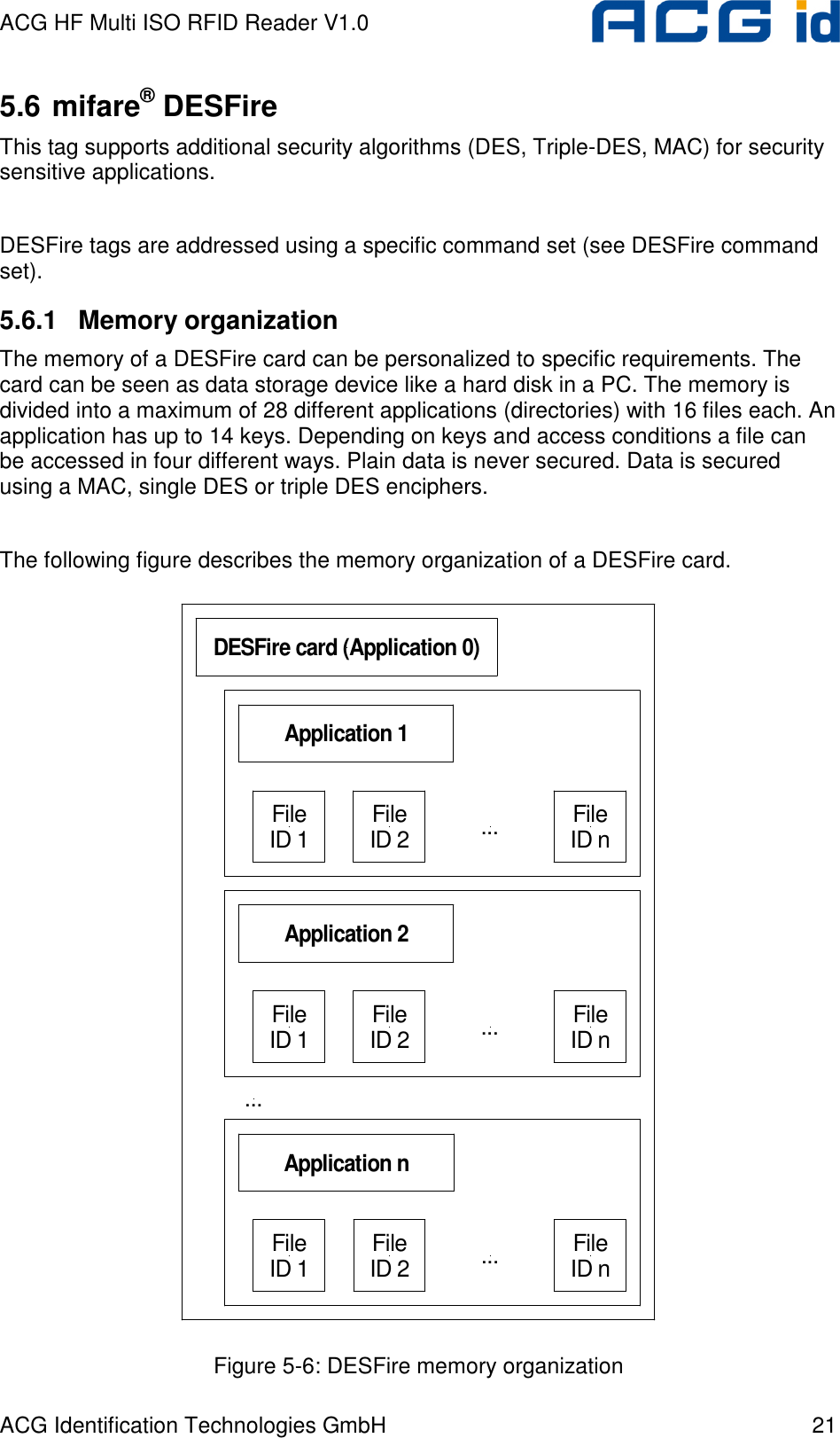
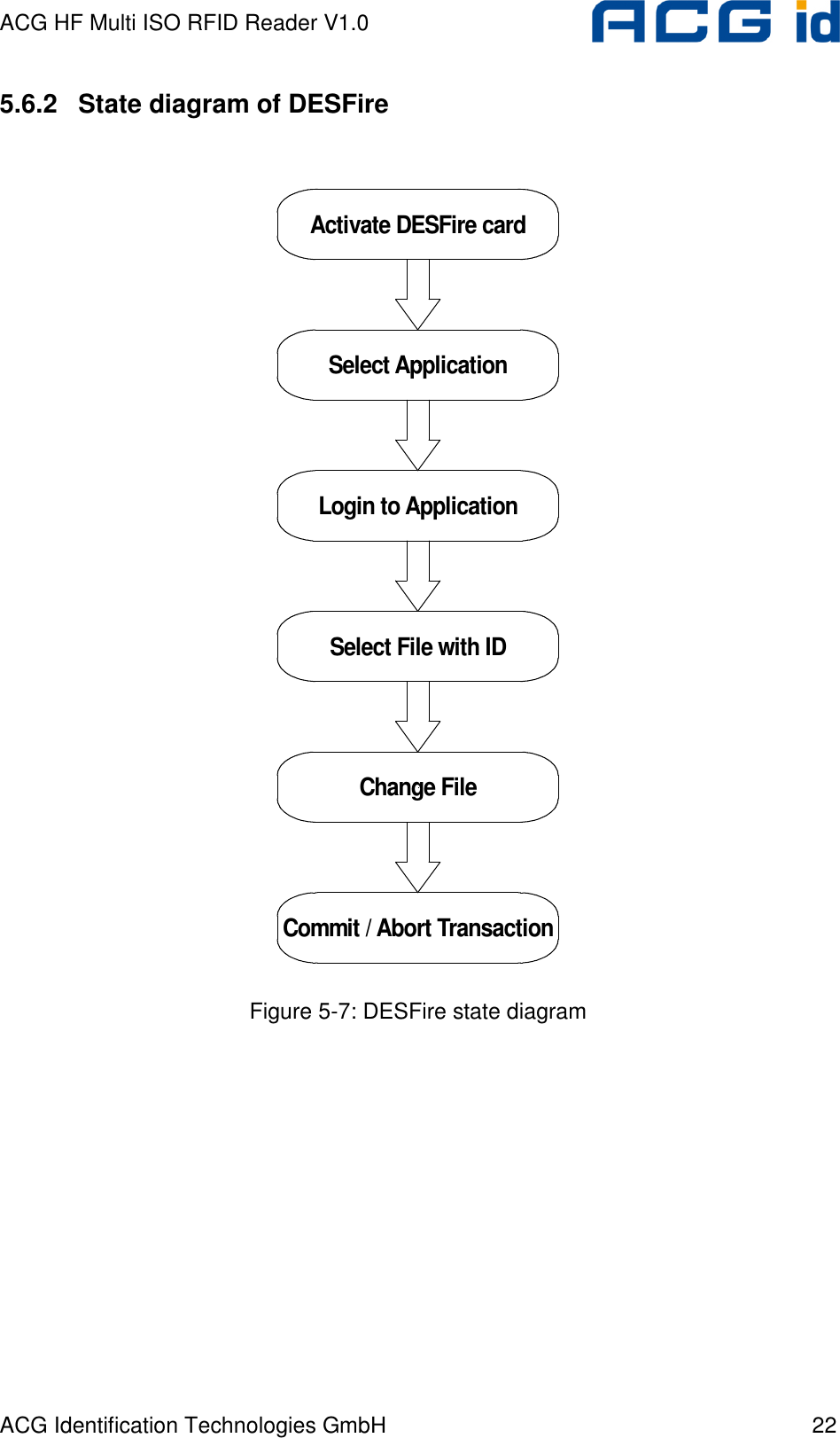
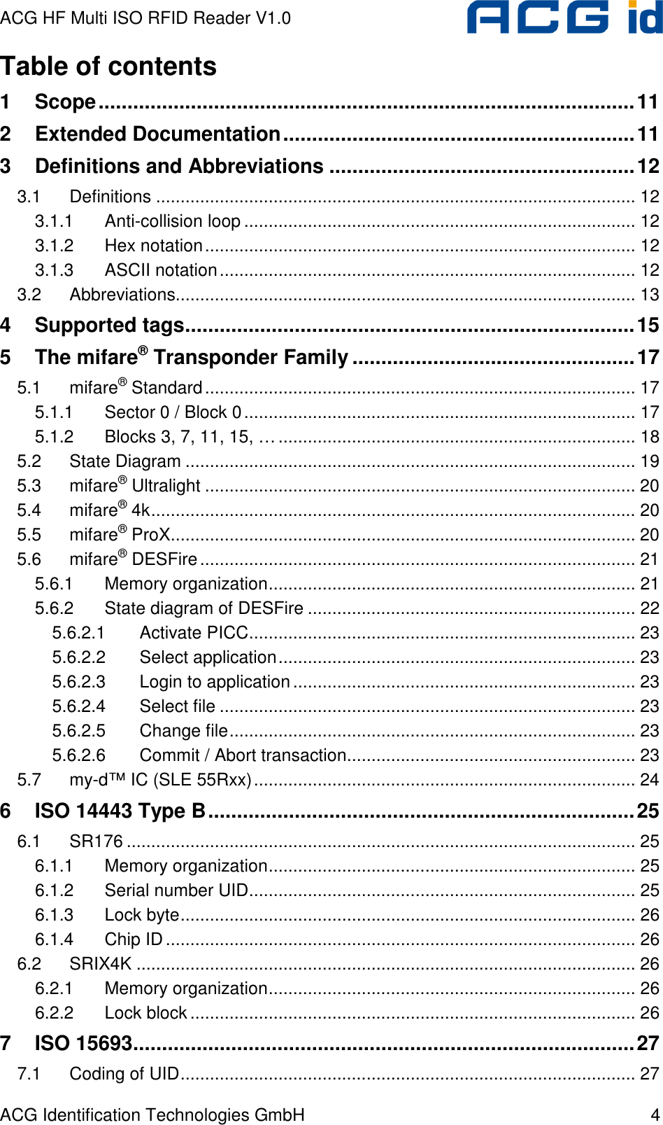
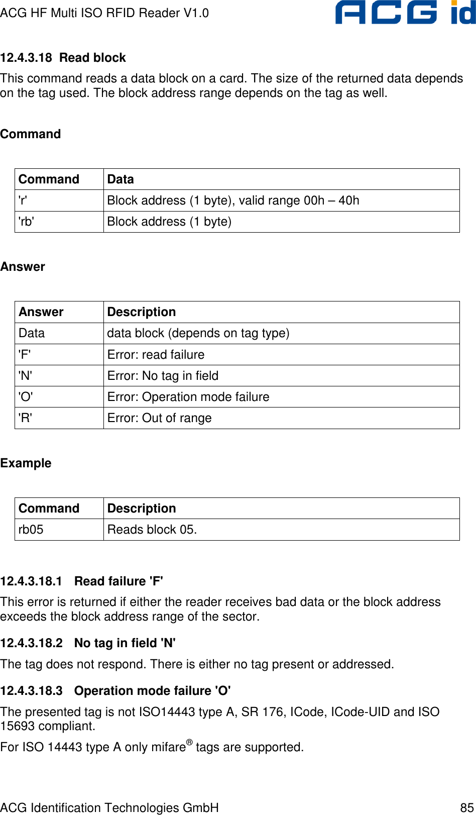
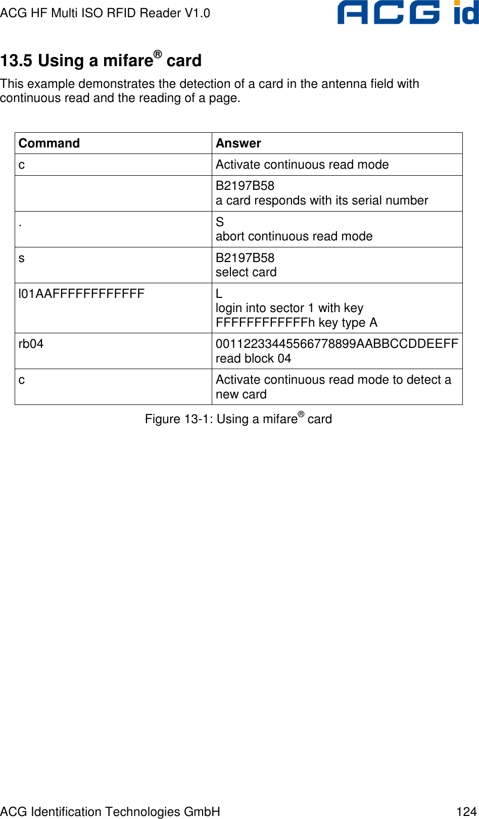
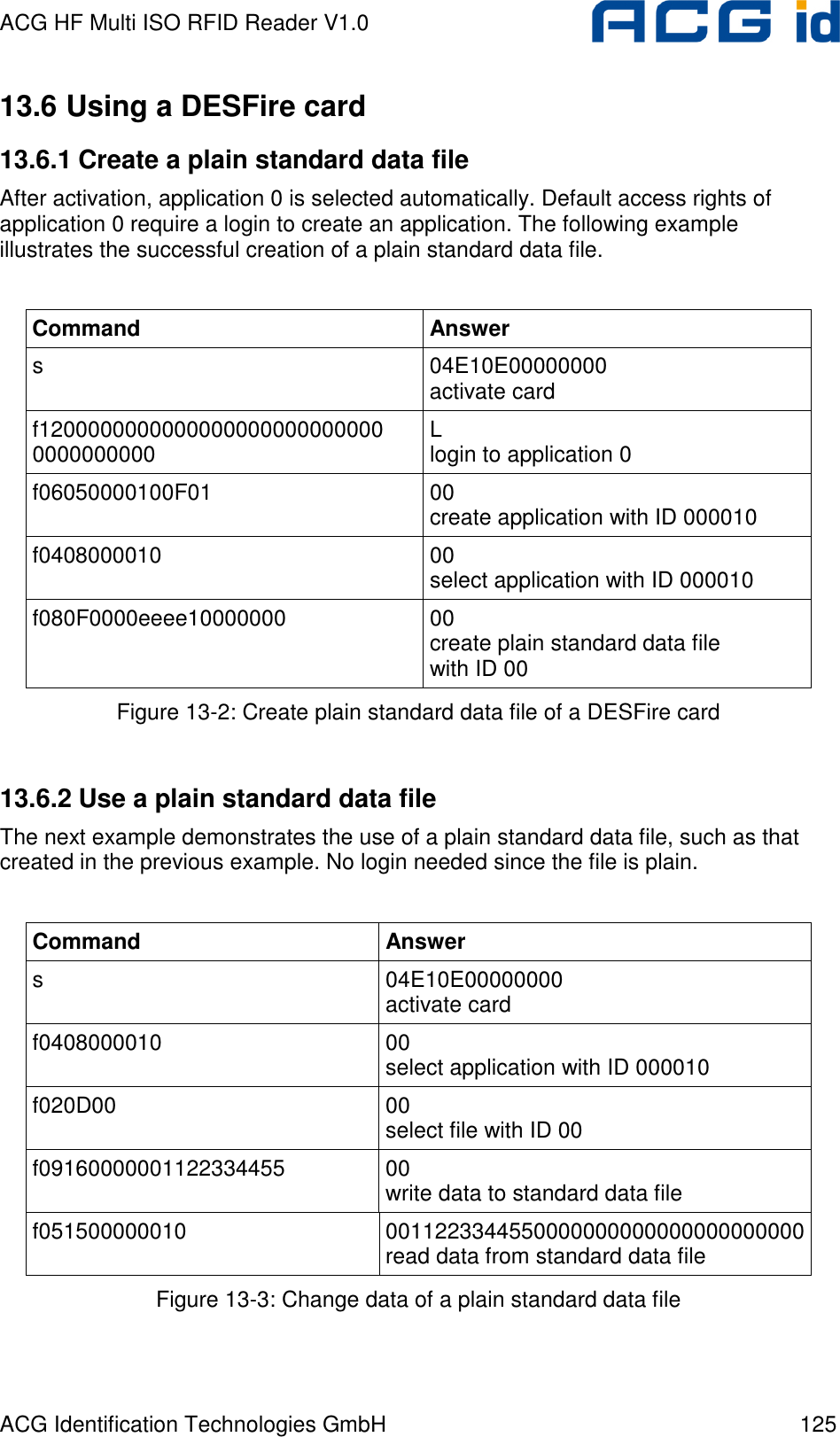
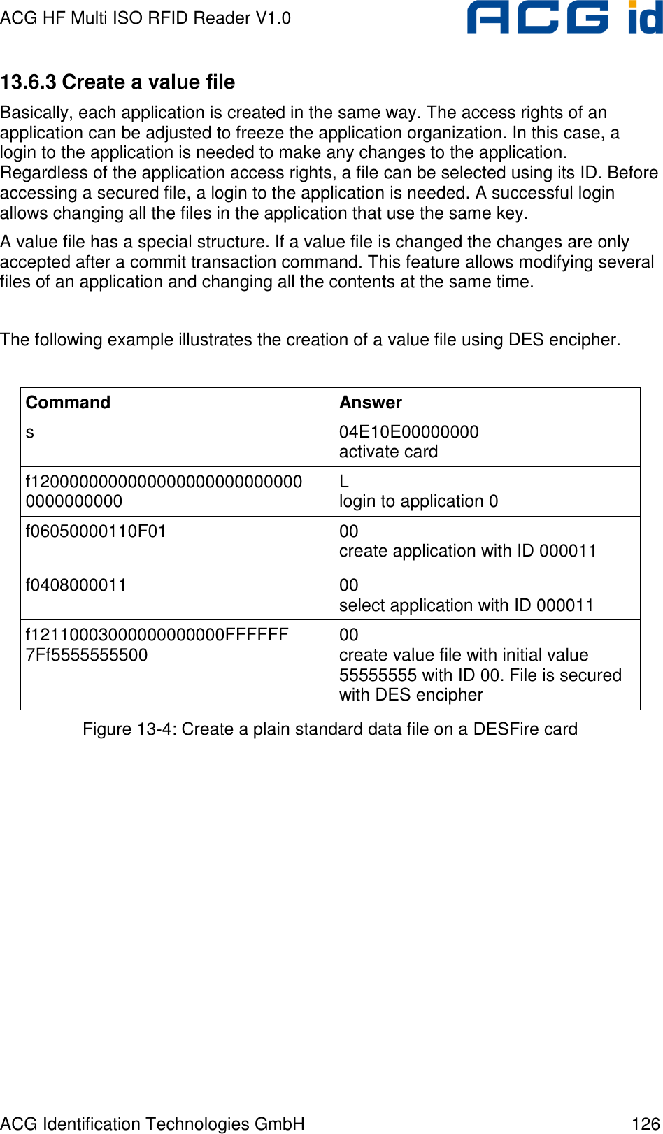
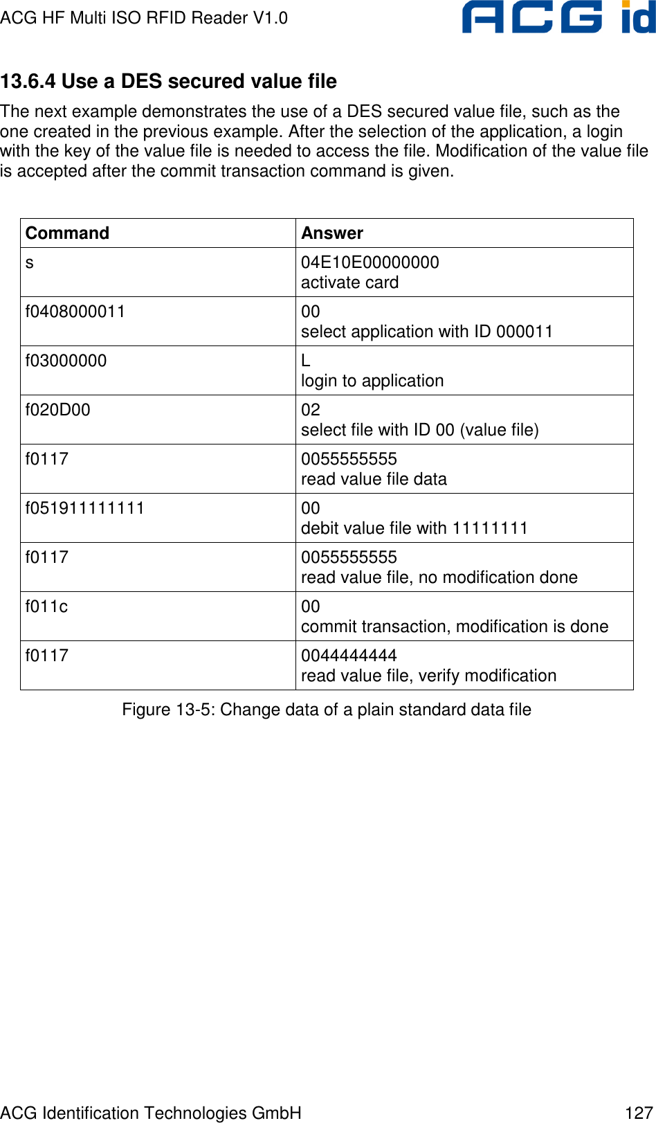
![ACG HF Multi ISO RFID Reader V1.0 ACG Identification Technologies GmbH 23 5.6.2.1 Activate PICC Before accessing a DESFire card, the card must be selected. A DESFire card has a 7 byte UID. After activation, the card is powered up and ready to accept a DESFire command. Application 0 is selected automatically. 5.6.2.2 Select application To jump into another application, the application has to be selected. An application can be seen as a directory, which contains up to 16 files. The size of the application depends on the stored files. 5.6.2.3 Login to application Specific access rights can be set for each application. Login to an application allows changing the organization of the application. Login to a file opens a secured file for access. A file can be accessed in four different ways: without any security or secured with MAC, single DES or triple DES. 5.6.2.4 Select file Before accessing a file, the file must be selected 5.6.2.5 Change file A selected file can be changed according its access rights. If a file is secured, a login is required before changes can be made. 5.6.2.6 Commit / Abort transaction Value files, backup files, linear record files and cyclic record files only adapt their values after the commit transaction command is given. Several files can be changed within an application at the same time. The abort transactions command annuls all changes within an application. Power loss will cancel all modifications too. For more details about application settings and access rights refer to [2].](https://usermanual.wiki/ASSALOY-Identification-Technologies/RDHC-0202N0-0X/User-Guide-702035-Page-24.png)
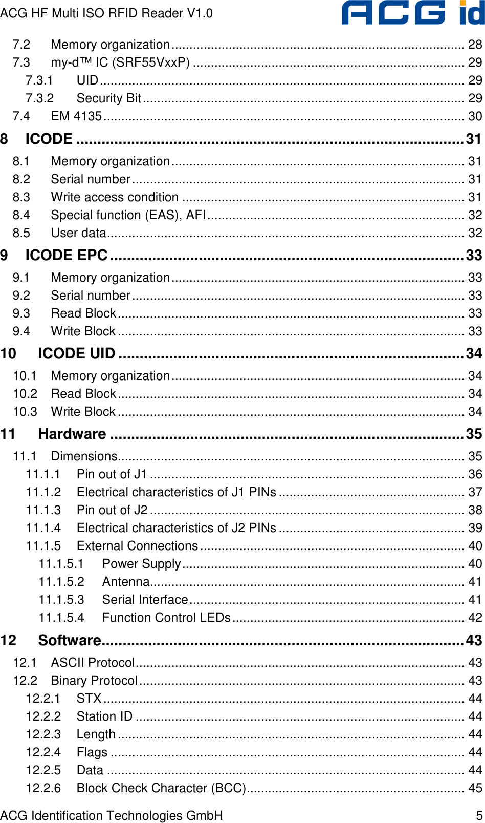
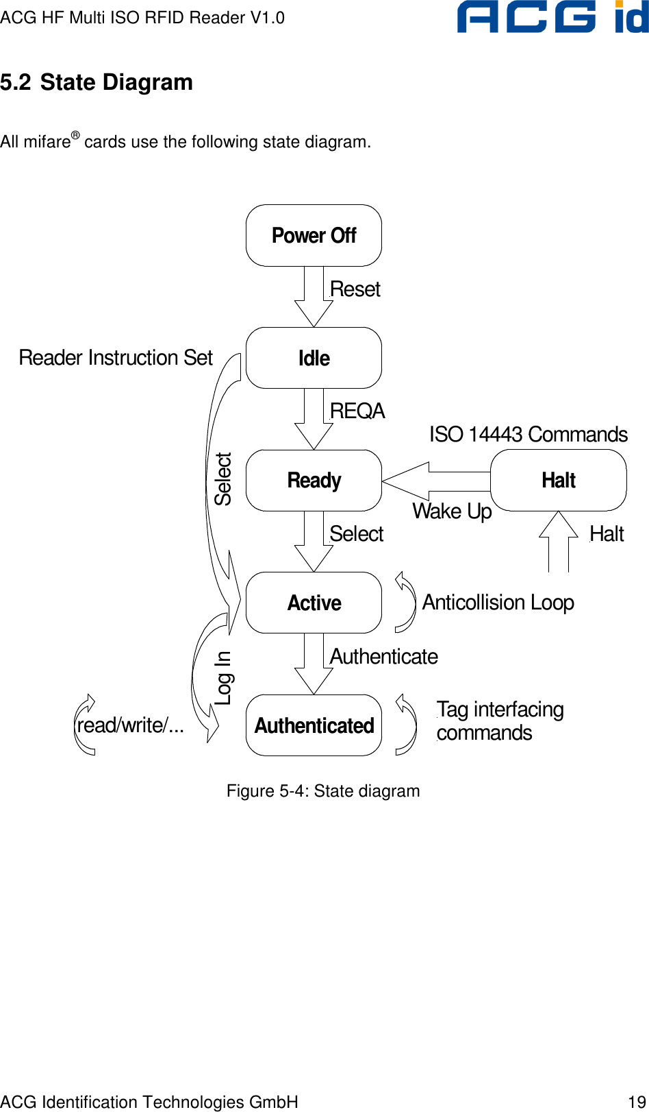
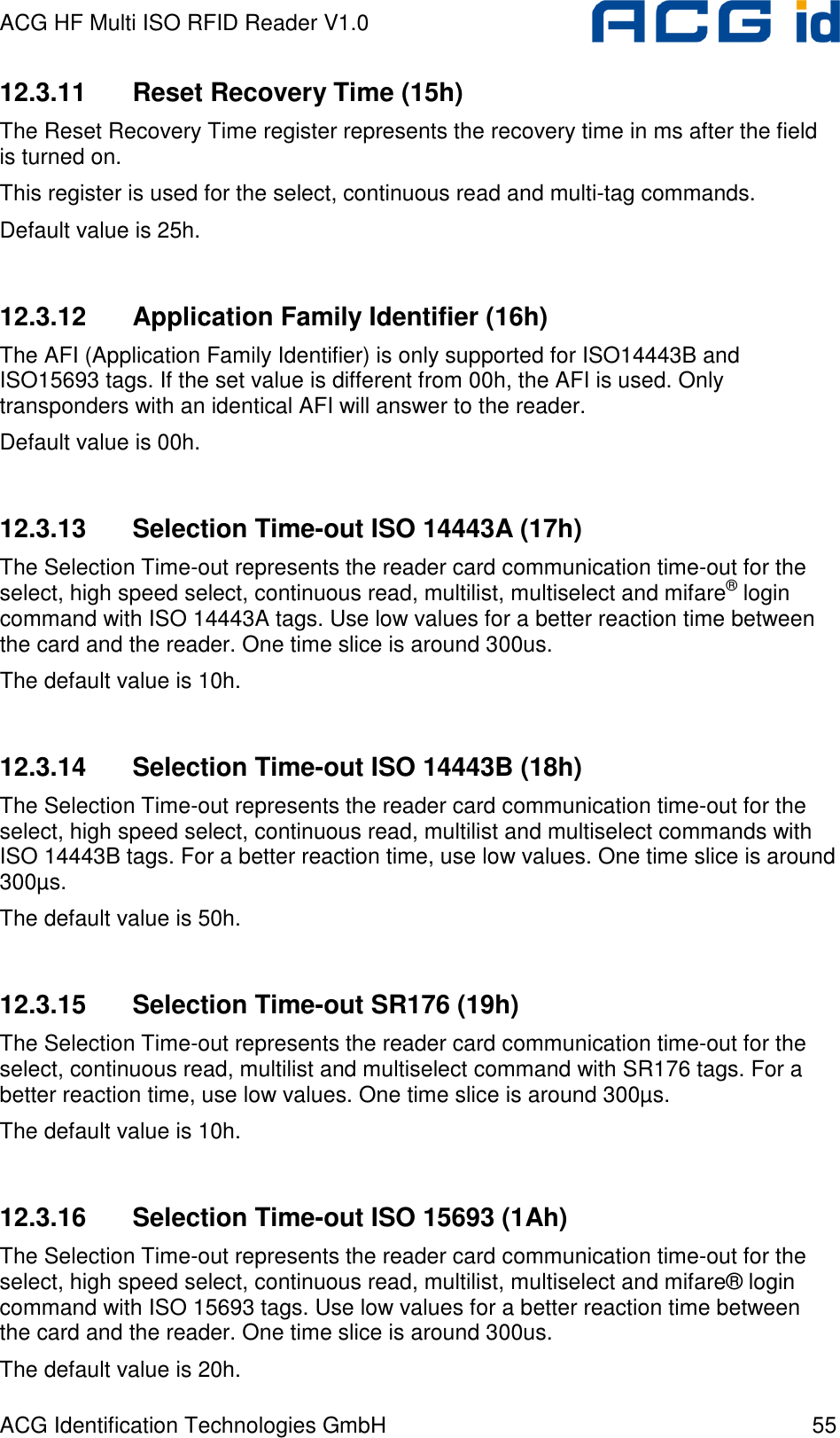
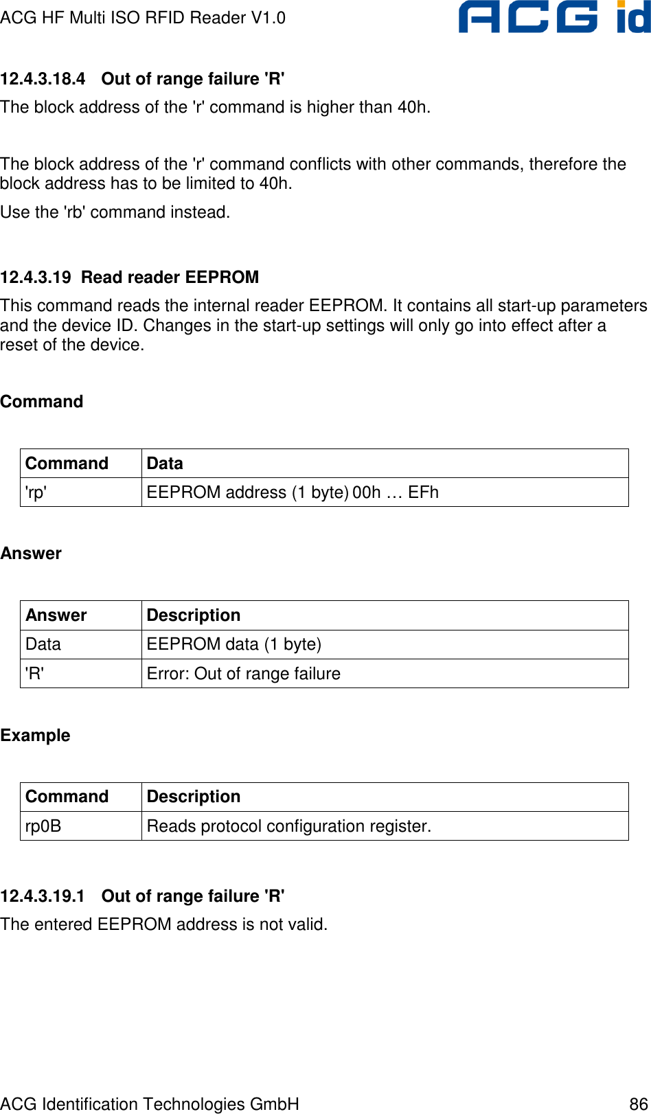
![ACG HF Multi ISO RFID Reader V1.0 ACG Identification Technologies GmbH 50 12.3.4.8 Extend ID (default 0) If Extended ID is set, the reader extends the serial number of tags with additional bytes. ISO 14443 A tags (5/8/11 bytes transmitted) Tag type Serial number 1 byte 4 / 7 / 10 bytes Figure 12-6: ISO 14443 A Extended Serial number The tag type byte indicates the type of cascade level. Tag type Description 00h Cascade level 1 transponder 01h Cascade level 2 transponder 02h Cascade level 3 transponder Figure 12-7: ISO 14443 A tag type ISO 14443 B tags (12 bytes transmitted) Serial number Application data Protocol info CID 4 bytes 4 bytes 3 bytes 1 byte Figure 12-8: ISO 14443 B Extended Serial number For detailed description of Application Data, Protocol Info and CID, refer to the ISO 14443 documentation [1].](https://usermanual.wiki/ASSALOY-Identification-Technologies/RDHC-0202N0-0X/User-Guide-702035-Page-51.png)
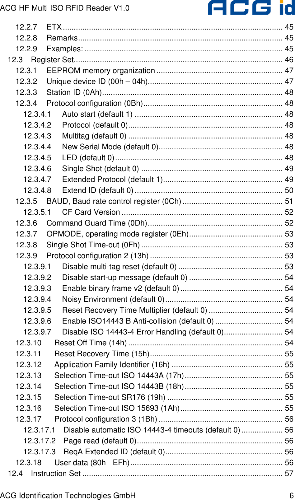
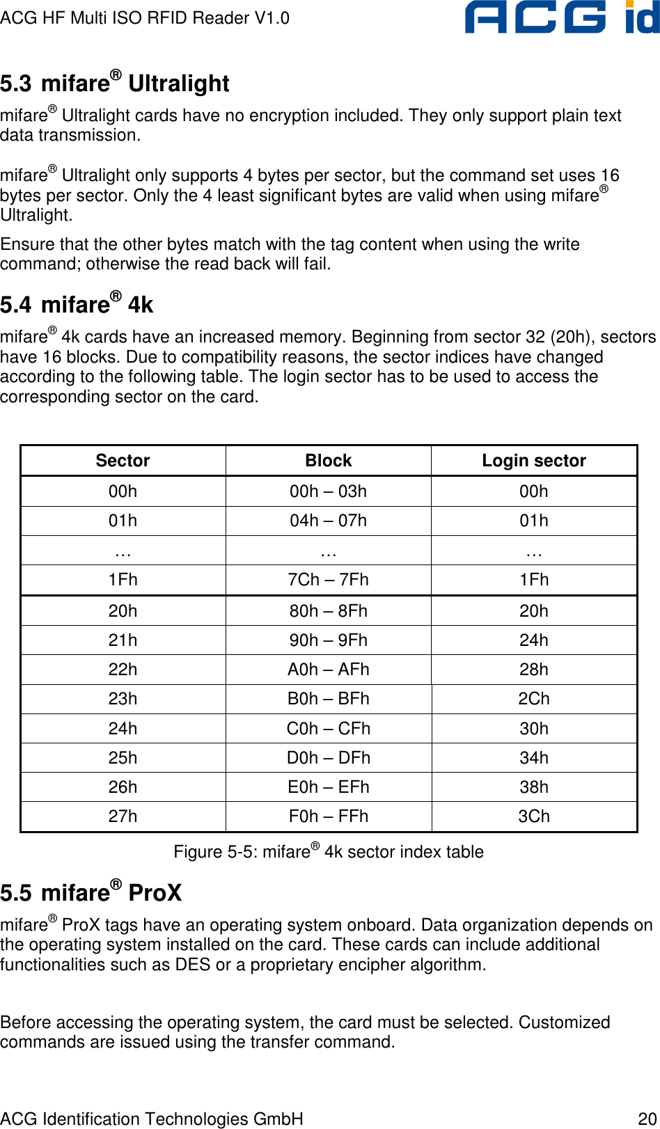
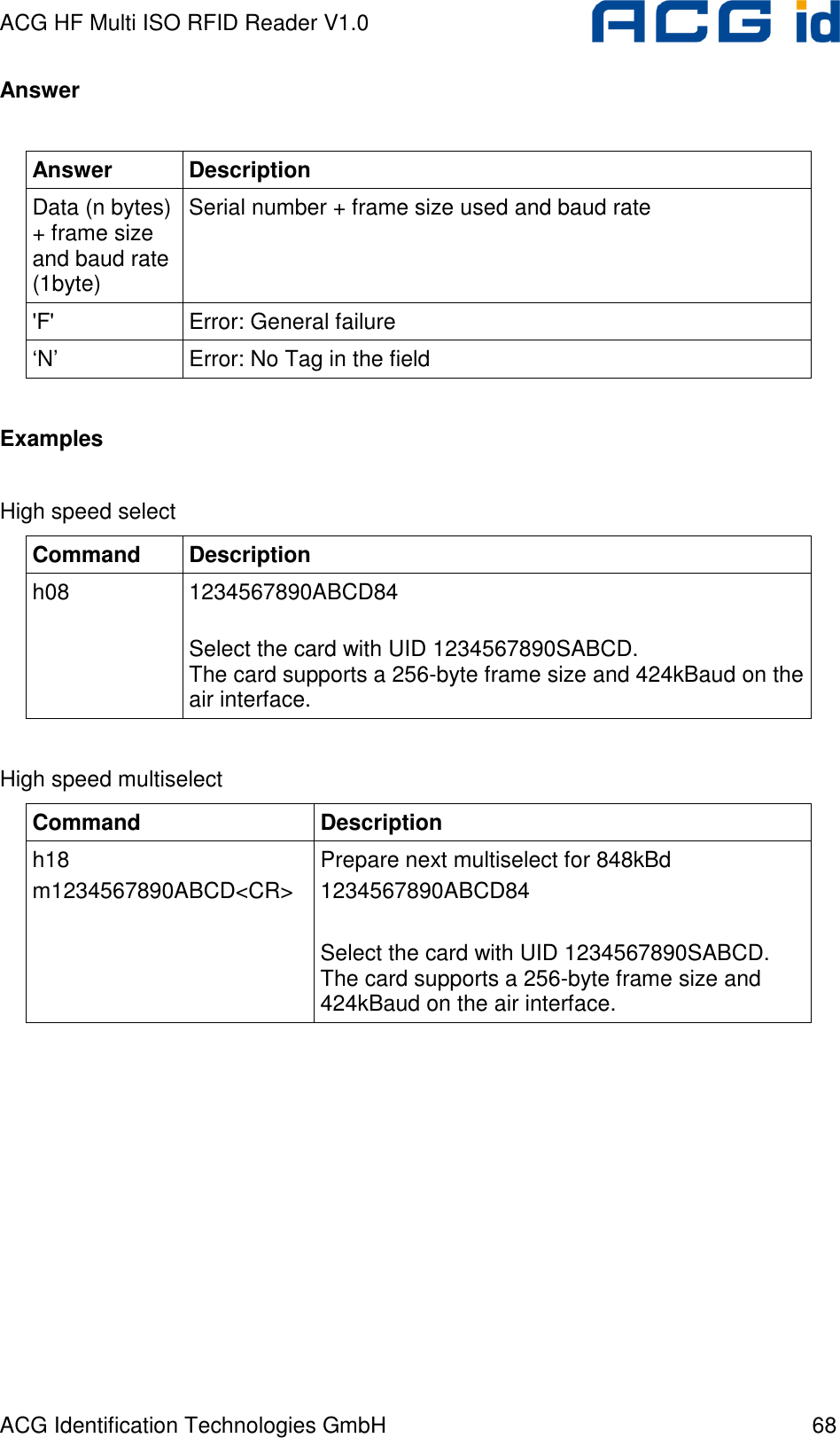
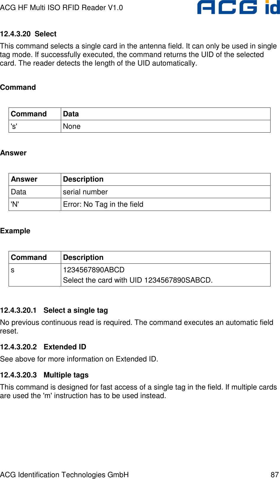
![ACG HF Multi ISO RFID Reader V1.0 ACG Identification Technologies GmbH 66 12.4.3.5.1 Time slotted answer In party line mode, more than one reader can be used simultaneously. The time slotted answer allows separating in time the answers from all connected devices. The station ID is used to determine the correct time slot. The reader supports up to 254 unique time slots. The following formula calculates the duration of one time slot (only one baud rate is supported per party line): 6*10][0BaudratesT = Figure 12-20: Time slot formula The following figure shows the timing diagram of time slotted answers. Timeslot 0 1 2 3 4 5 … 252 253 254 T0 T1 T2 T3 T4 T5 T252 T253 T254 HOST 'g' → Reader (01) ← 01 Reader (03) ← 03 Reader (04) ← 04 Reader (254) ← 254 Figure 12-21: Timing diagram of time slotted answers](https://usermanual.wiki/ASSALOY-Identification-Technologies/RDHC-0202N0-0X/User-Guide-702035-Page-67.png)
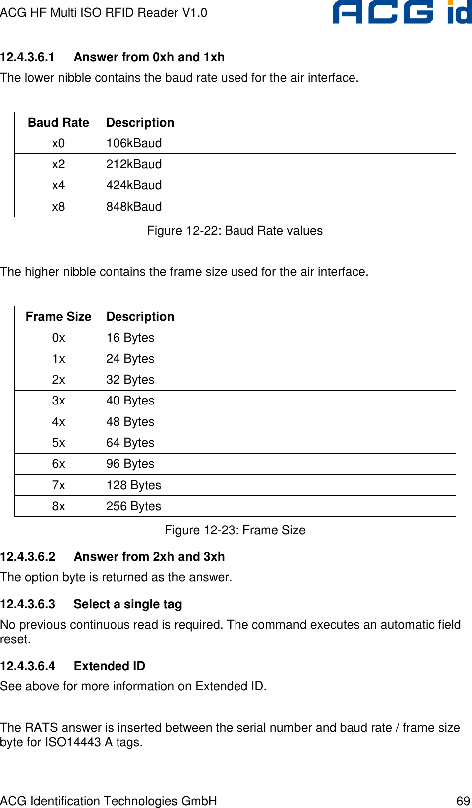
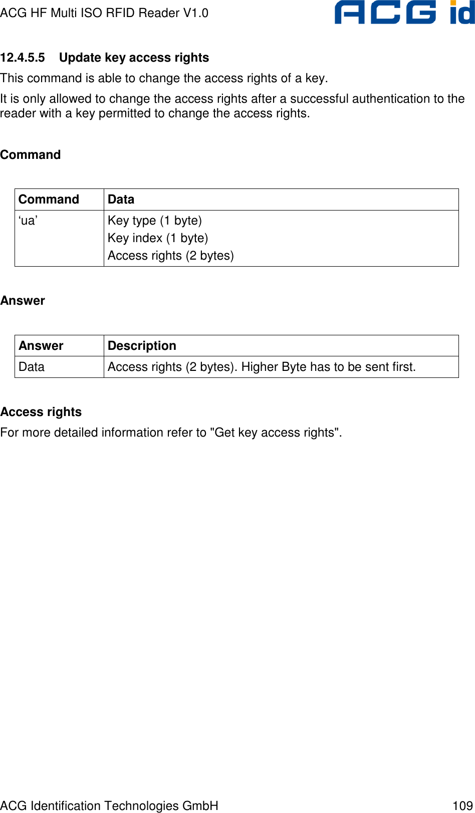
![ACG HF Multi ISO RFID Reader V1.0 ACG Identification Technologies GmbH 107 12.4.5.3 Get key status This command reports the key status of the reader. The reader lists for each key the key information. This command is used to inform the key management about the key status. The first byte of the response lists the number of stored keys. Command Command Data ‘it’ key type (1) Answer Answer Description my-d™ secure Data Number of keys (1 byte) [Key information (8 bytes)] • Free User part (1 byte) • Project ID (3 bytes) • Logical Sector ID (1 byte) • Key type (1 byte) • KVV (2 bytes) DES Data Number of keys (1 byte) [Key information (10 bytes)] • Option byte (1 byte) • Free User part (9 bytes) mifare® Data Number of keys (1 byte) [Key information 10 bytes)] • Free User part (10 bytes) More than 255 bytes If the amount of data exceeds 255 bytes, than the answer is divided into more frames. If a frame follows, the Number of keys byte is extended with a set MSB (80h).](https://usermanual.wiki/ASSALOY-Identification-Technologies/RDHC-0202N0-0X/User-Guide-702035-Page-108.png)
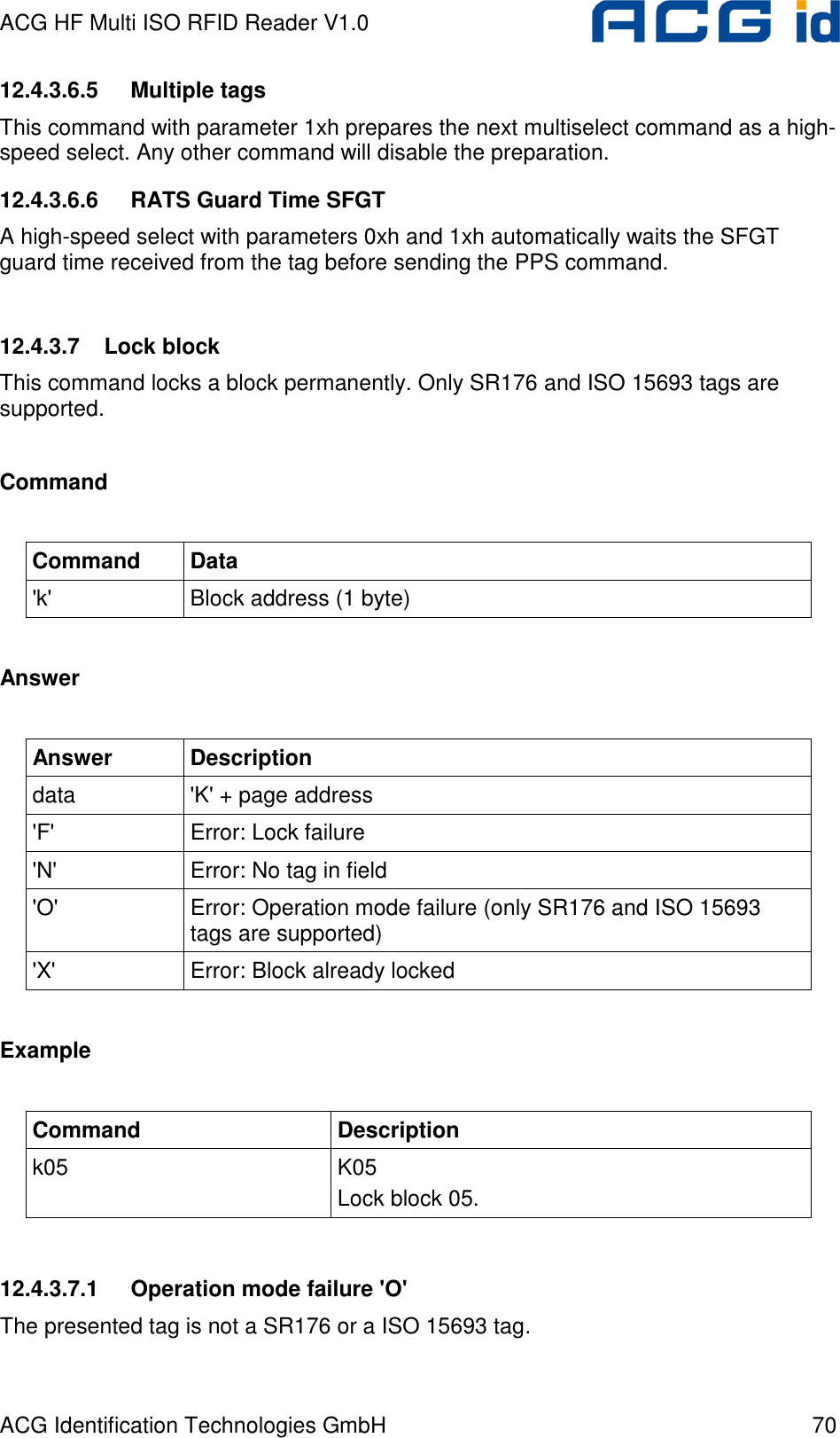
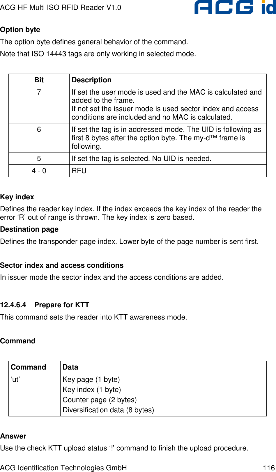
![ACG HF Multi ISO RFID Reader V1.0 ACG Identification Technologies GmbH 114 Command Command Data ‘as’ Option byte (1 byte) [UID (8 bytes)] Key page (1 byte) Key index (1 byte) Counter page (2 byte) Diversification data (8 bytes) Answer Answer Description ‘L’ In case of success Option byte The option byte defines the general behavior of the command. Note that ISO 14443 tags are only working in selected mode. Bit Description 7 RFU 6 If set the tag is in addressed mode. The UID is following as first 8 bytes after the option byte. The my-d™ frame is following. 5 If set the tag is selected. No UID is needed. 4 - 0 RFU Key page This byte defines the key page number of the transponder Key index Defines the reader key index. If the index exceeds the key index of the reader the error ‘R’ out of range is thrown. The key index is zero based. Counter page](https://usermanual.wiki/ASSALOY-Identification-Technologies/RDHC-0202N0-0X/User-Guide-702035-Page-115.png)
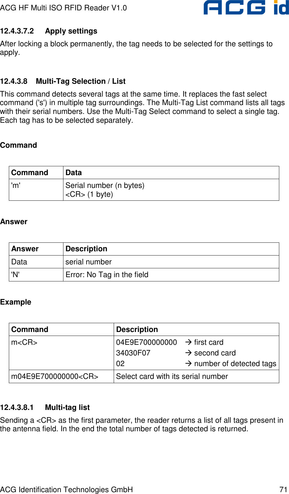
![ACG HF Multi ISO RFID Reader V1.0 ACG Identification Technologies GmbH 115 This page number points to the authentication counter page. Lower byte of the page number is sent first. Diversification data This data is used to diversify the key data. Example Command Answer / Description 'as20040103000000000000000000' 'L' Login into tag. 12.4.6.3 Issue transponder key Writes a diversified key to the transponder. This command uses the write and Reread my-d™ command. Command Command Data ‘ik’ Option byte (1 byte) [UID (8 bytes)] Key index (1 byte) Destination page (2 bytes) Diversification data (8 bytes) [Sector index and access conditions (2 bytes)] Answer Answer Description ‘IK’ Key successfully written](https://usermanual.wiki/ASSALOY-Identification-Technologies/RDHC-0202N0-0X/User-Guide-702035-Page-116.png)
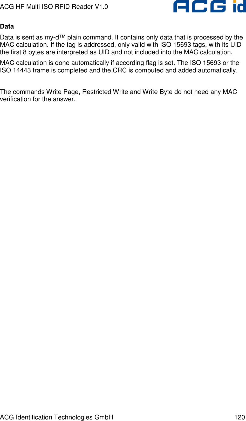
![ACG HF Multi ISO RFID Reader V1.0 ACG Identification Technologies GmbH 119 12.4.6.5 my-d™ command This command sends and receives my-d™ plain and secure commands including my-d™ secure algorithm. Command Command Data ‘z’ Downlink length (1 byte) Option byte (1 byte) [UID (8 bytes)] my-d™ data (n bytes) Answer Answer Description Data Status byte: 00h (1 byte) Data without MAC and CRC (n bytes) Downlink length This byte is mandatory. It will define the length of the my-d™ data frame sent to the reader. The MAC, CRC and the framing overhead is not included. Option byte The option byte defines general behavior of the command. Note that ISO 14443 tags are only working in selected mode. Bit Description 7 If set the MAC is calculated and added to the frame 6 If set the tag is in addressed mode. The UID is following as first 8 bytes after the option byte. The my-d™ frame is following. 5 If set the tag is selected. No UID is needed. 4 - 0 RFU](https://usermanual.wiki/ASSALOY-Identification-Technologies/RDHC-0202N0-0X/User-Guide-702035-Page-120.png)
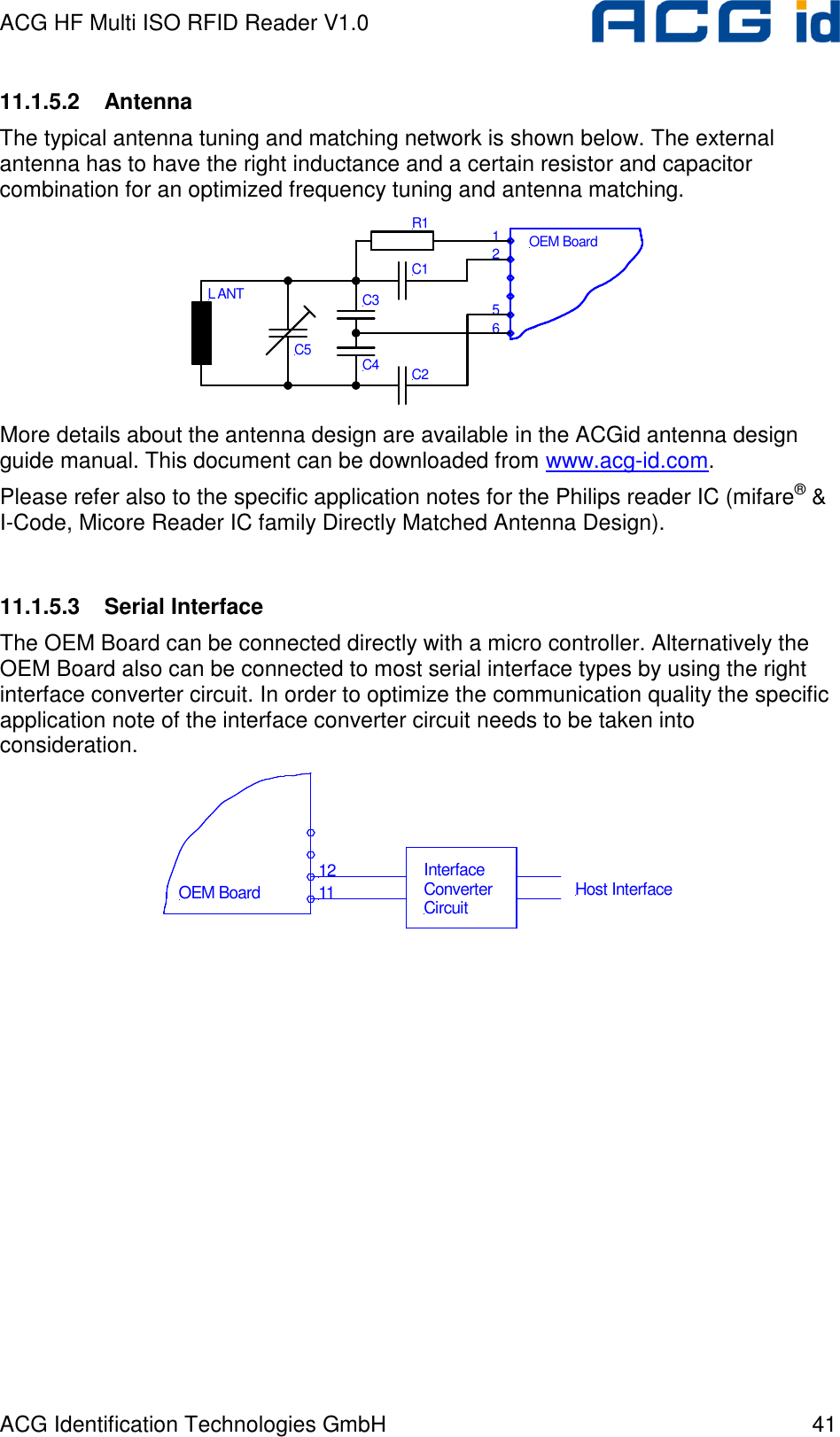
![ACG HF Multi ISO RFID Reader V1.0 ACG Identification Technologies GmbH 129 14 References [1] ISO/IEC 14443 Part 1-4, Identification Cards – Contact less integrated circuit(s) cards – Proximity cards [2] DESFire Documentation, Philips, http://www.semiconductors.philips.com [3] Data Encryption Standard (DES), FIPS PUB 46-3, Reaffirmed 1995 October 25 [4] ACG Antenna Design Guide [5] Philips; Application Note, mifare® & I-Code, Micore Reader IC family Directly Matched Antenna Design](https://usermanual.wiki/ASSALOY-Identification-Technologies/RDHC-0202N0-0X/User-Guide-702035-Page-130.png)

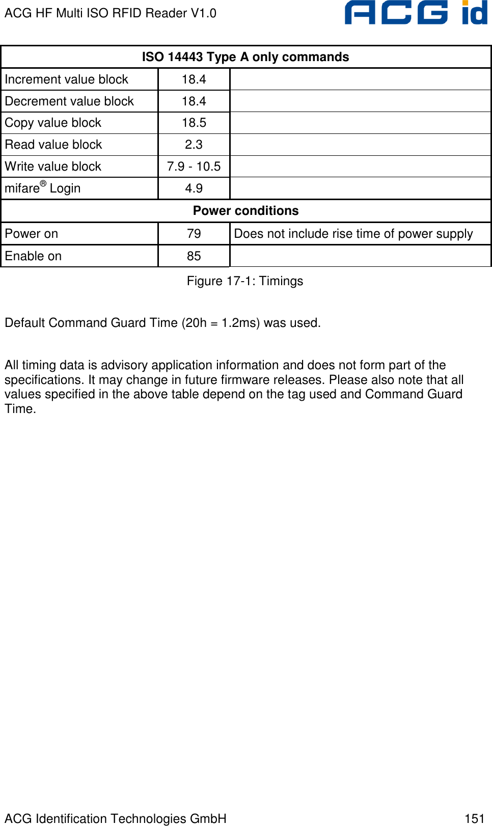
![ACG HF Multi ISO RFID Reader V1.0 ACG Identification Technologies GmbH 150 17 Appendix C: Timings tCMD tEXEC tRES PC: Request → Reader: ← Response Command tEXEC [ms] Comments Common commands Cont. read (locked tag) 2.8 – 22.6 + Reset Off and Recovery Time Cont. read (worst case) 54 + 3x Reset Off and Recovery Time DES en/decryption 9.6 – 9.7 TDES en/decryption 28.7 – 28.8 Highspeed select 'h08' (locked tag) 8.9 – 14.4 + Reset Off and Recovery Time + SFGT Highspeed select 'h08' (no tag) 15 + 3x Reset Off and Recovery Time Highspeed select 'h08' (worst case) 14.7 + 3x Reset Off and Recovery Time + SFGT Multiselect (locked tag) 5.8 – 11.4 + Reset Off and Recovery Time Multiselect (no tag) 67 + Reset Off and Recovery Time Multiselect (worst case) 67 + Reset Off and Recovery Time Antenna on 0.2 + Reset Recovery Time Antenna off 0.2 Port read 0.1 Port write 0.1 Read block 1.8 – 2.2 Write block 8.2 – 11 Reset 13.2 Select (locked tag) 5.4 – 22.8 + Reset Off and Recovery Time Select (no tag) 38 + 3x Reset Off and Recovery Time Select (worst case) 55 + 3x Reset Off and Recovery Time](https://usermanual.wiki/ASSALOY-Identification-Technologies/RDHC-0202N0-0X/User-Guide-702035-Page-151.png)