ASSALOY Identification Technologies RDHS-0404D1-0X RFID Reader User Manual
ASSA ABLOY Identification Technologies GmbH RFID Reader
UserManual.wiki
>
ASSALOY Identification Technologies
>
RDHS 0404D1 0X User Manual
User Manual
Navigation menu
Upload a User Manual
Namespaces
Wiki Guide
HTML
PDF
Info
Views
User Manual
Discussion / Help
Navigation
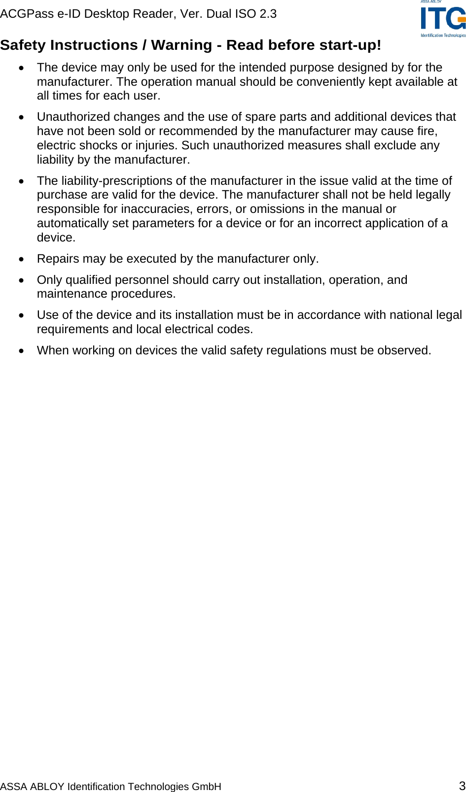
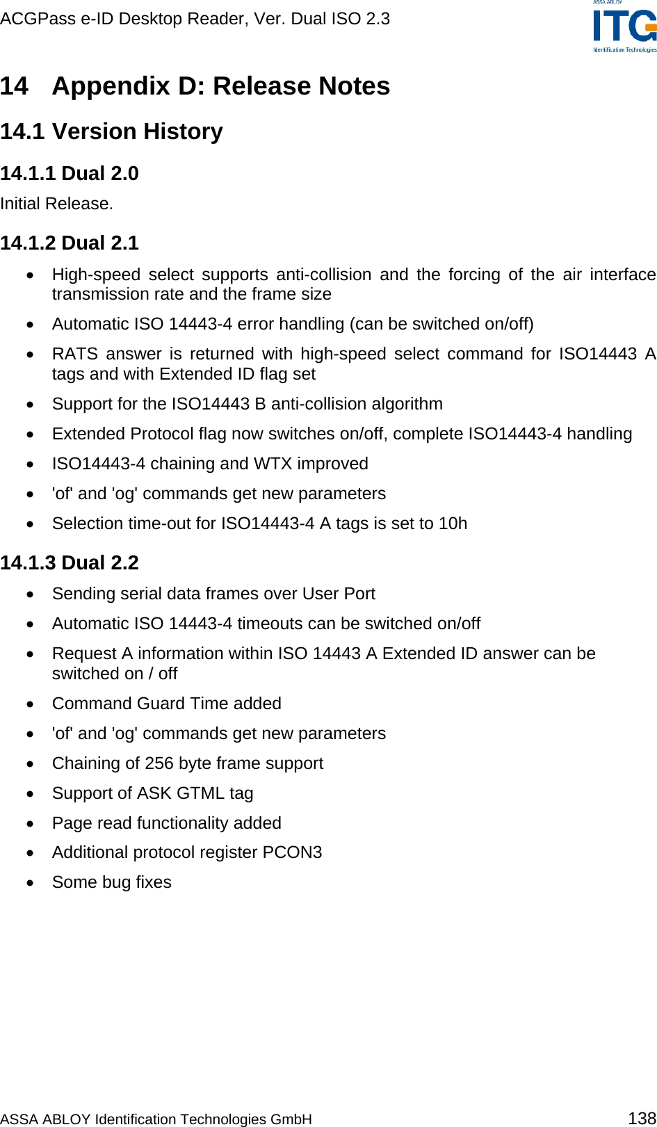
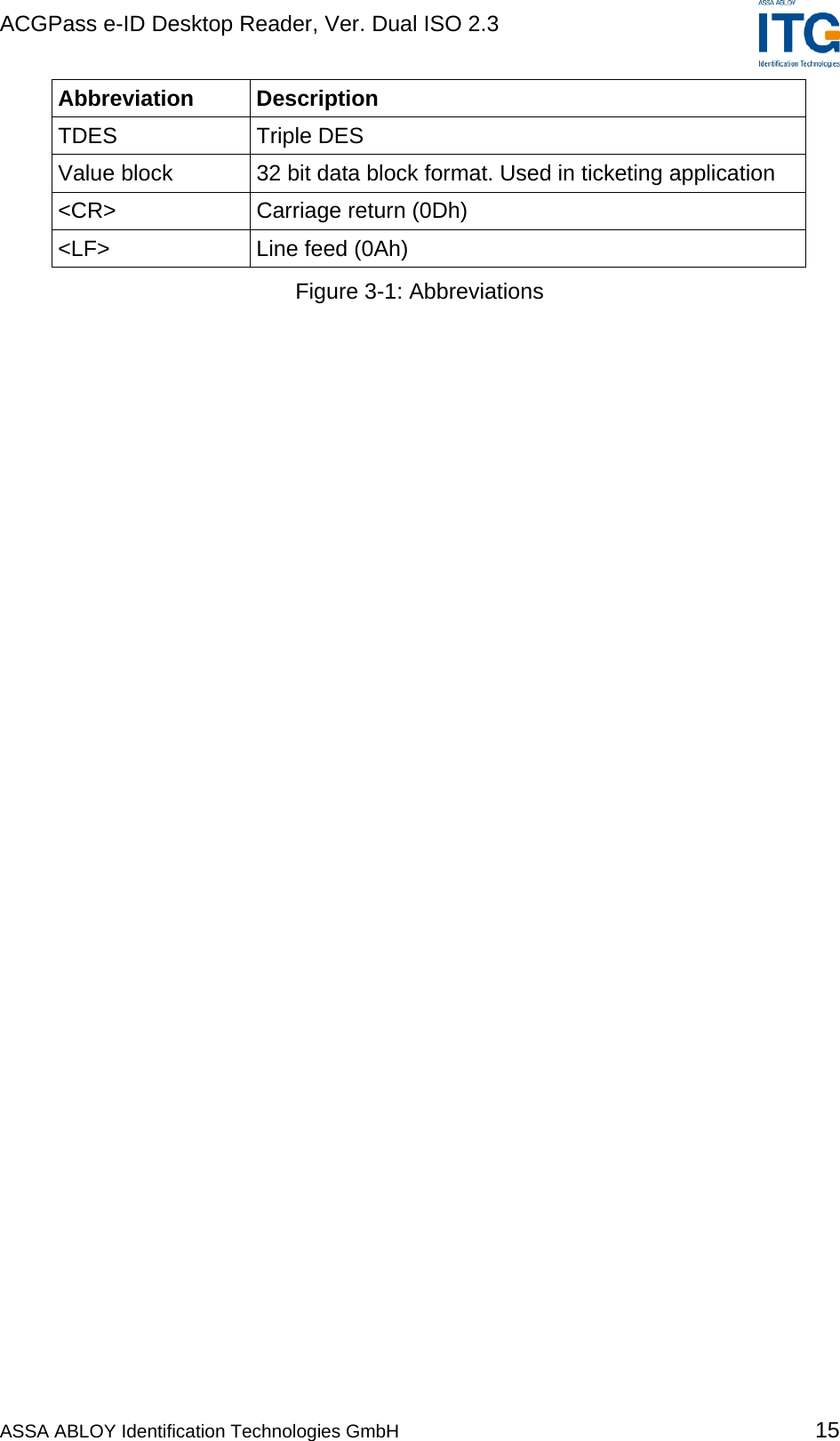
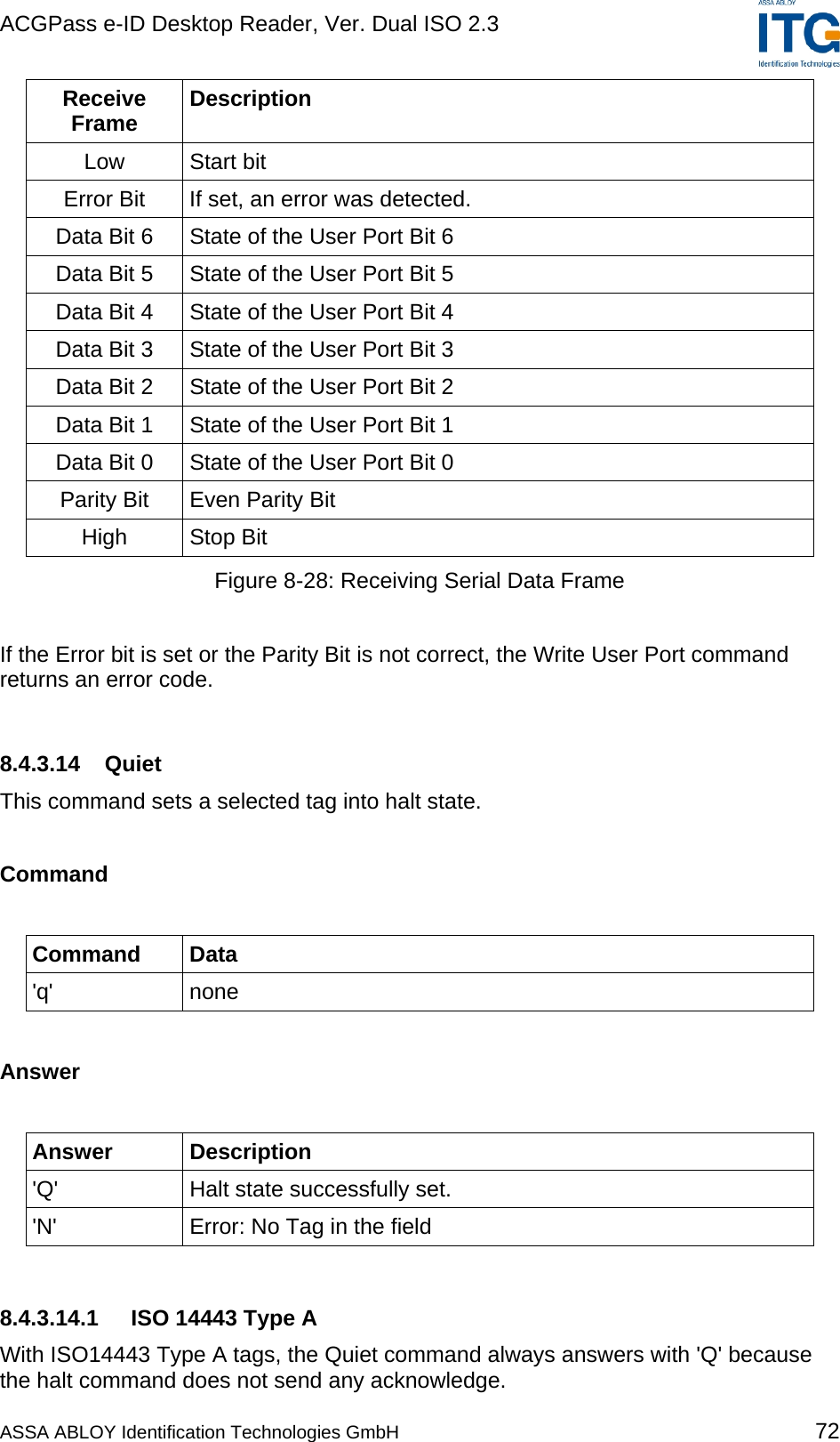
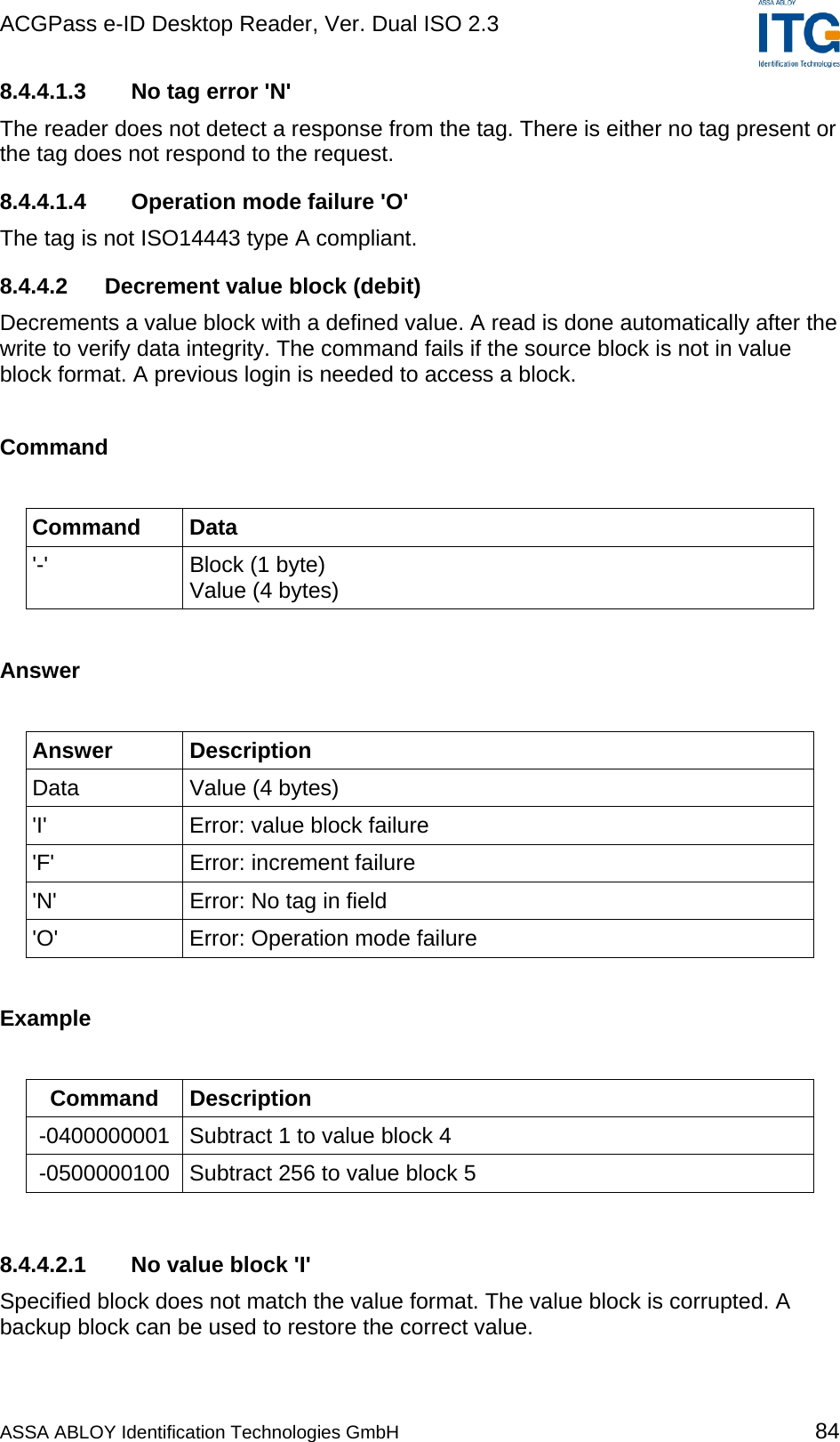
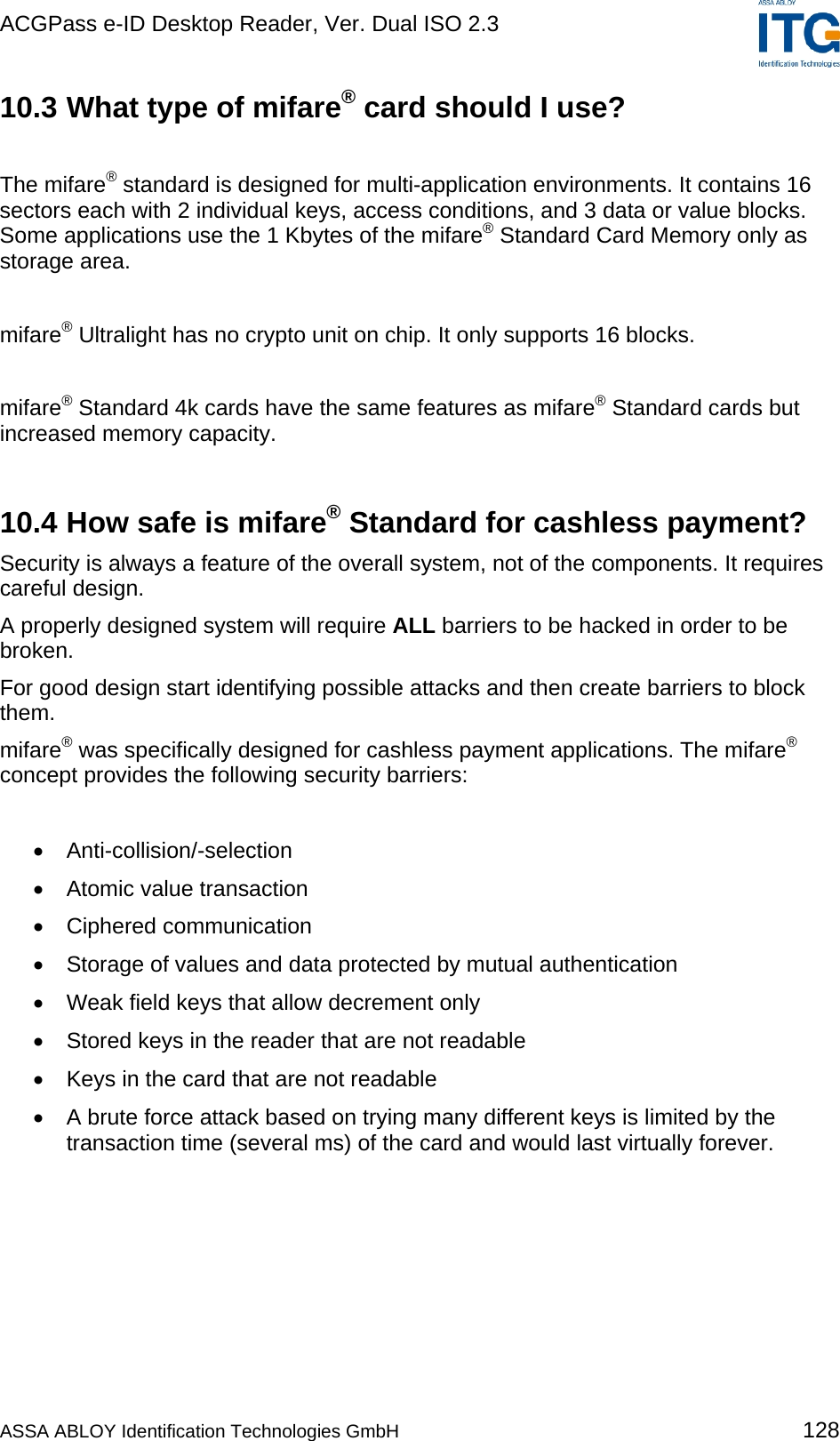
![ACGPass e-ID Desktop Reader, Ver. Dual ISO 2.3 3.2 Abbreviations Abbreviation Description AID Application ID ASCII American Standard Code for Information Interchange ATR Answer to Reset ATS Answer to Select Block For the mifare® Standard one block contains 16 bytes CID Card Identifier (logical card address, ISO 14443-4) CRC Cyclic Redundancy Check DES Data Encryption Standard, for more details about DES refer to [3]. EDC Error Detection Code EOF End of Frame Hex / xxh Value in Hexadecimal notation I-block Information block LSB Least Significant Bit or Byte MSB Most Significant Bit or Byte NAD Node Address (ISO 14443-4) OSI Open System Interconnection OTP One time programmable PCB Protocol Control Byte (ISO 14443-4) PCON Protocol Configuration byte of the reader PPS Protocol and Parameter Selection RATS Request for Answer to Select R-block Receive ready block REQA Request ISO Type A REQB Request ISO Type B RFU Reserved for Future Use S-block Supervisory block Sector For the mifare® Standard one sector contains 4 blocks SID Station ID SFGT Guard time after RATS SN Serial Number of a tag (a 32 bit number) SOF Start of frame ASSA ABLOY Identification Technologies GmbH 14](https://usermanual.wiki/ASSALOY-Identification-Technologies/RDHS-0404D1-0X/User-Guide-795138-Page-15.png)
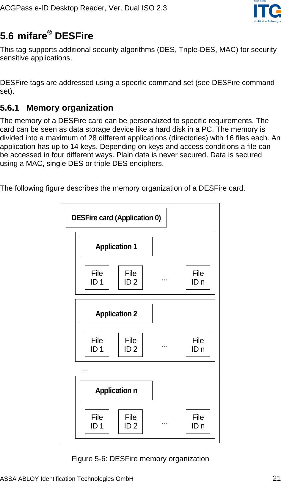
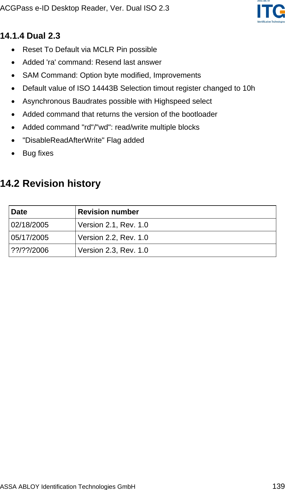
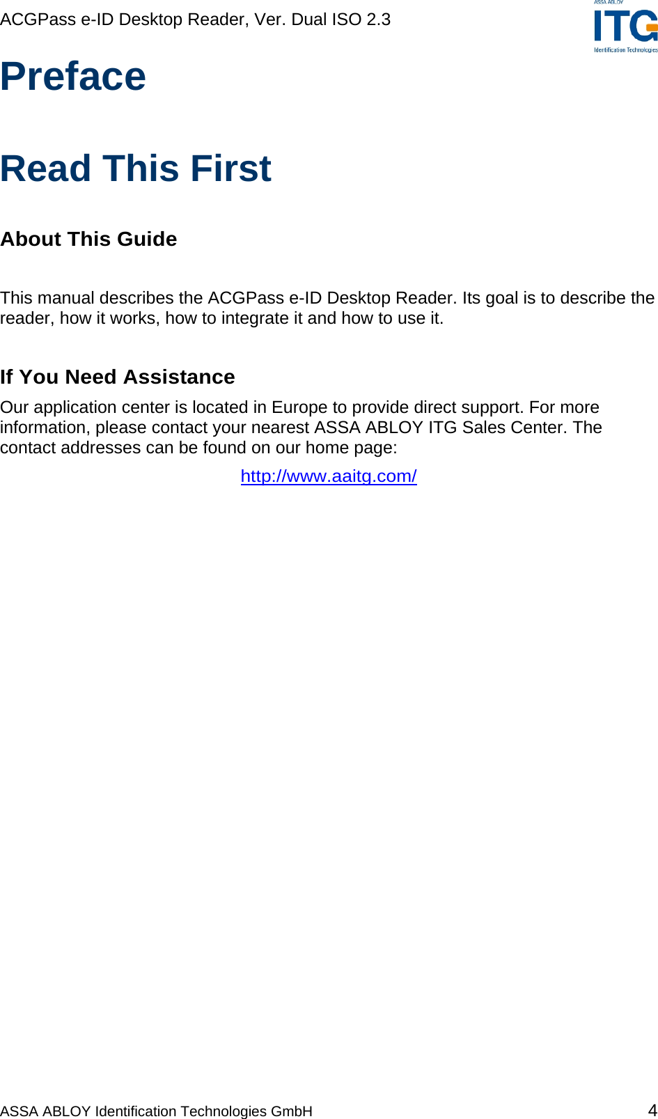
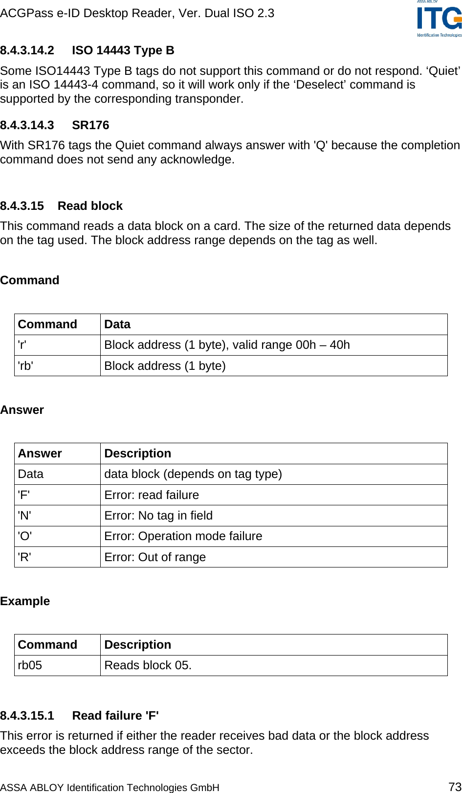
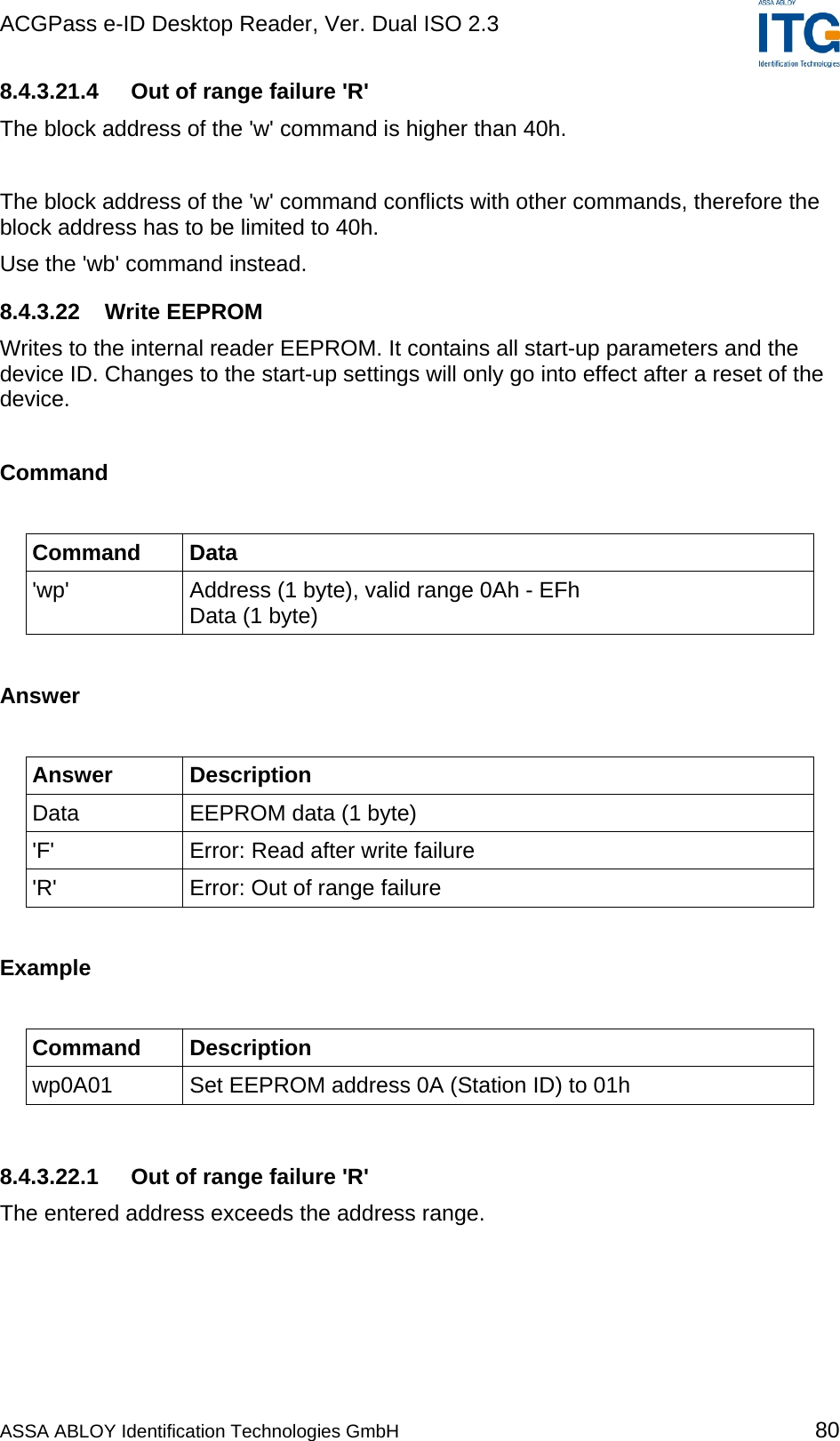
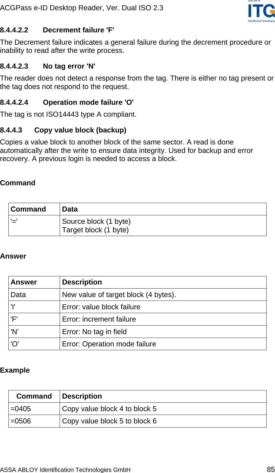
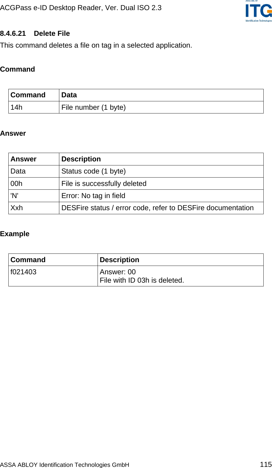
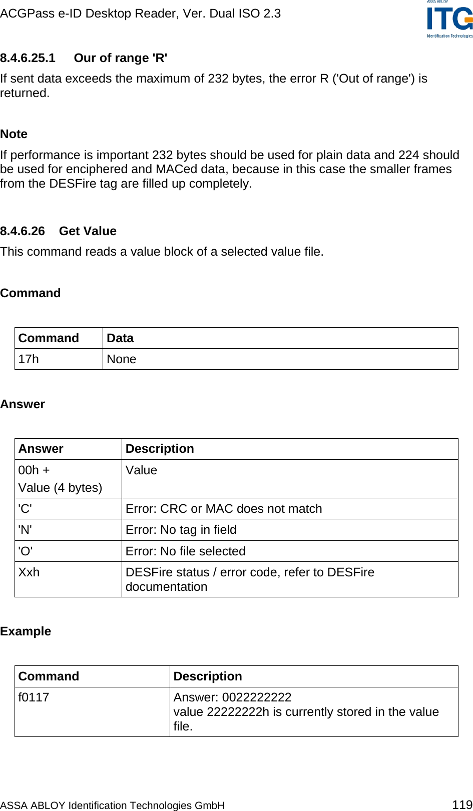
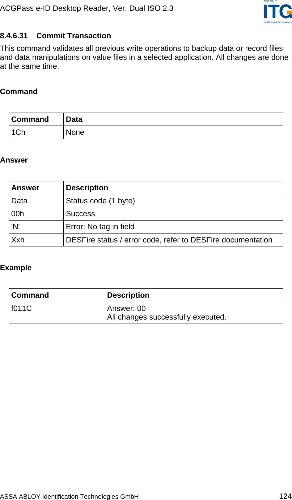
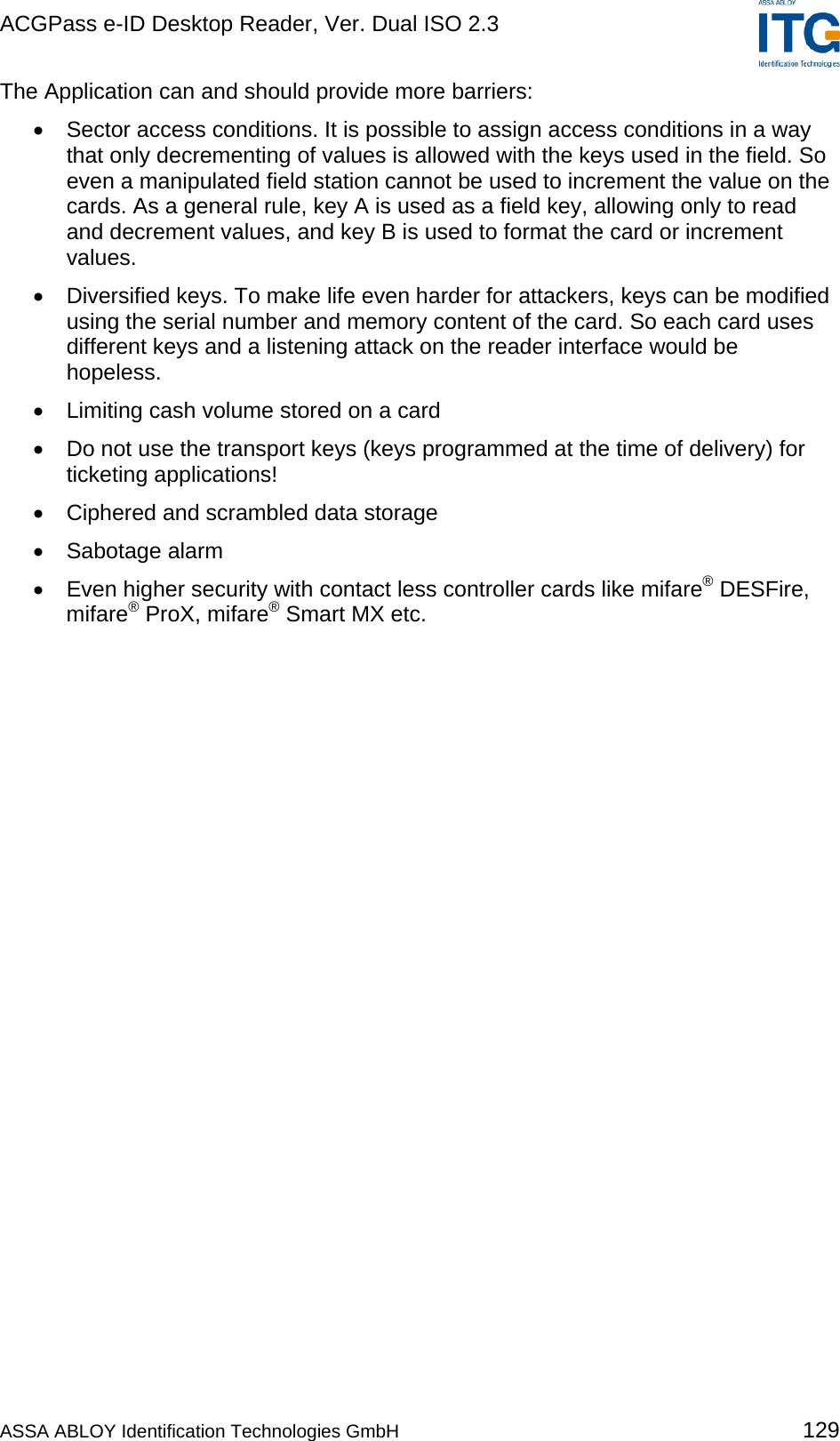
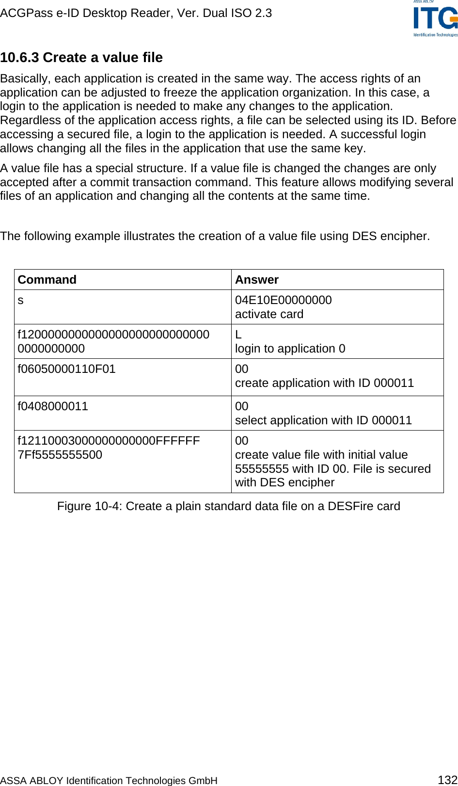
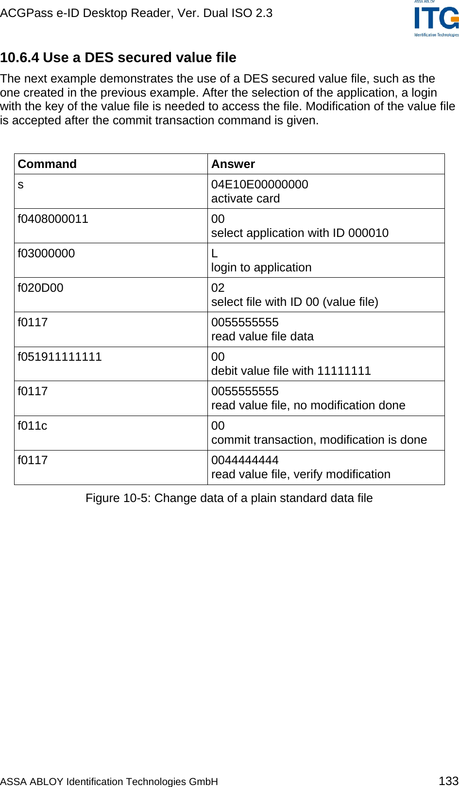
![ACGPass e-ID Desktop Reader, Ver. Dual ISO 2.3 5.6.2.1 Activate PICC Before accessing a DESFire card, the card must be selected. A mifare® DESFire card has a 7 byte UID. After activation, the card is powered up and ready to accept a mifare® DESFire command. Application 0 is selected automatically. 5.6.2.2 Select application To jump into another application, the application has to be selected. An application can be seen as a directory, which contains up to 16 files. The size of the application depends on the stored files. 5.6.2.3 Login to application Specific access rights can be set for each application. Login to an application allows to change the organization of the application. Login to a file opens a secured file for access. A file can be accessed in four different ways: without any security or secured with MAC, single DES or triple DES. 5.6.2.4 Select file Before accessing a file, the file must be selected 5.6.2.5 Change file A selected file can be changed according its access rights. If a file is secured, a login is required before changes can be made. 5.6.2.6 Commit / Abort transaction Value files, backup files, linear record files and cyclic record files only adapt their values after the commit transaction command is given. Several files can be changed within an application at the same time. The abort transactions command annuls all changes within an application. Power loss will cancel all modifications too. For more details about application settings and access rights refer to [2]. ASSA ABLOY Identification Technologies GmbH 23](https://usermanual.wiki/ASSALOY-Identification-Technologies/RDHS-0404D1-0X/User-Guide-795138-Page-24.png)
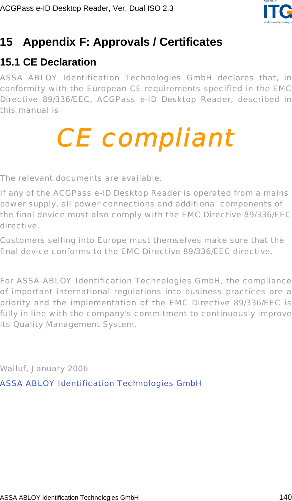
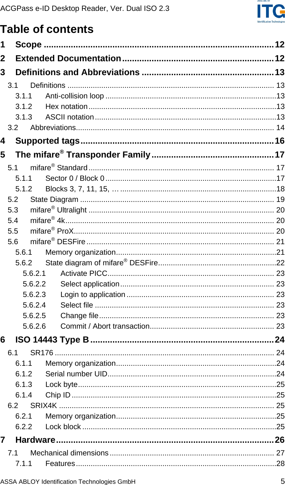
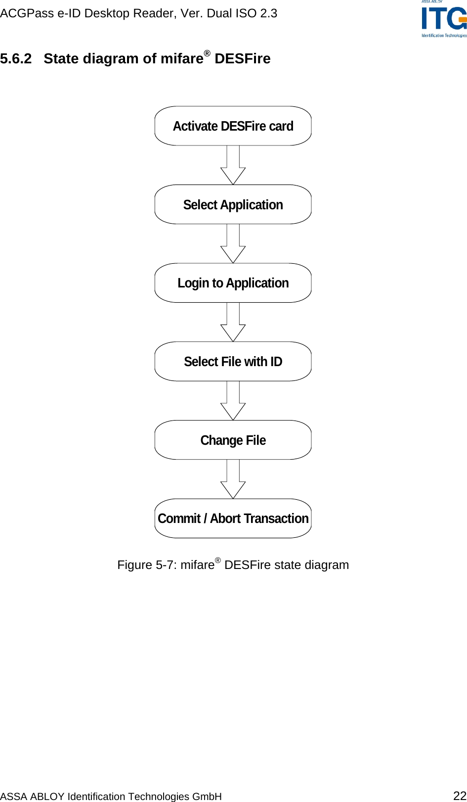
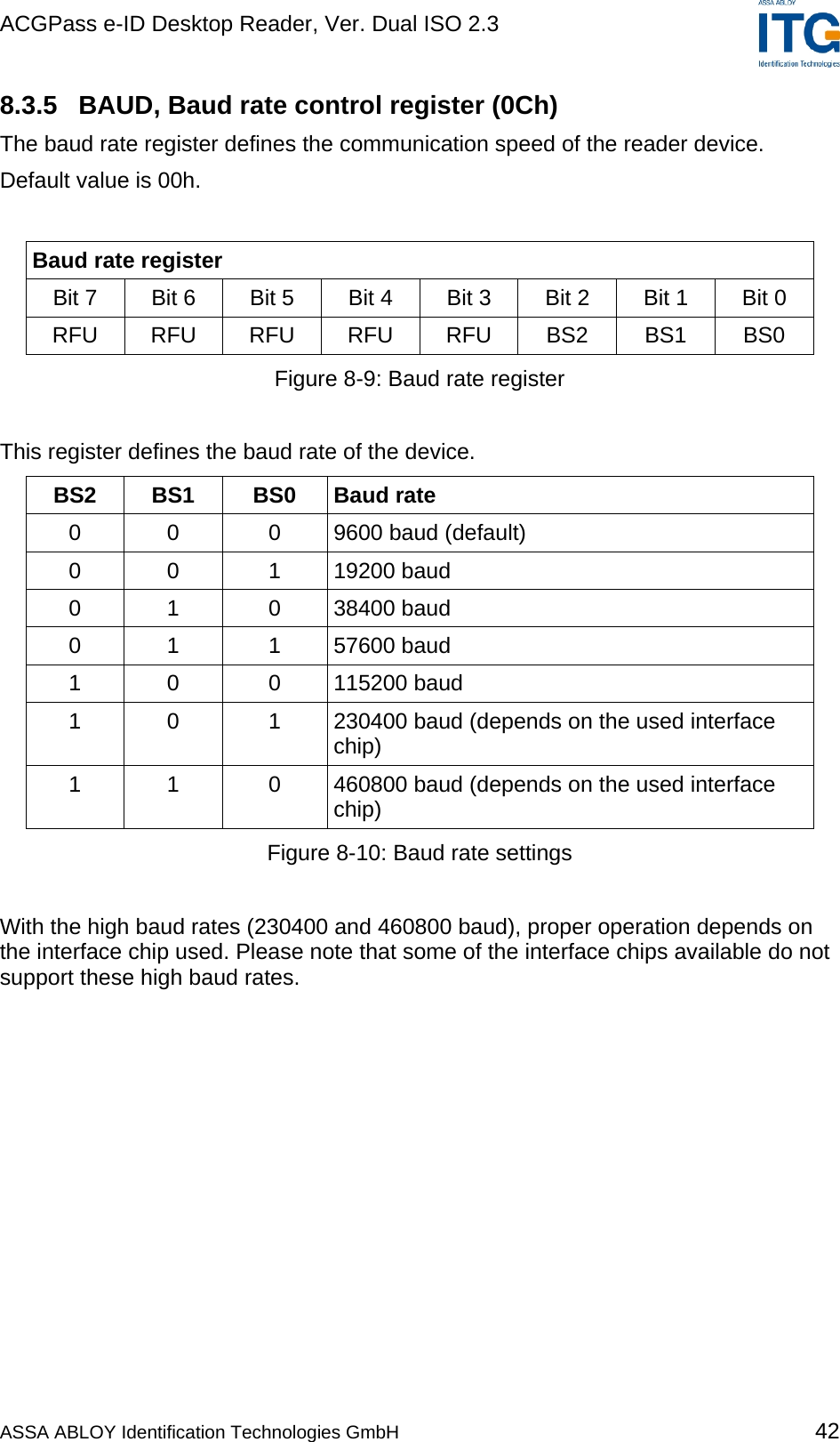
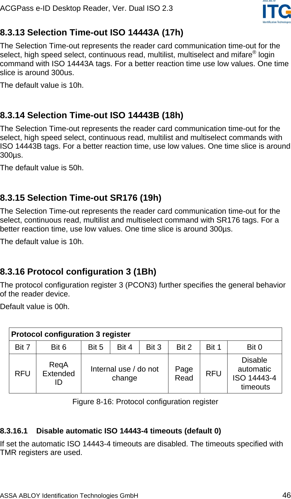
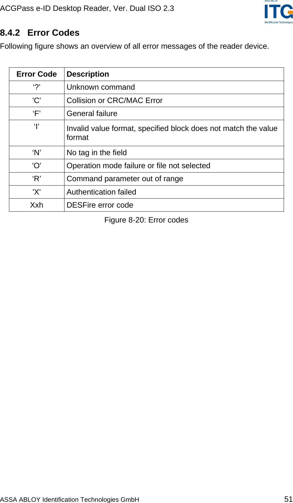
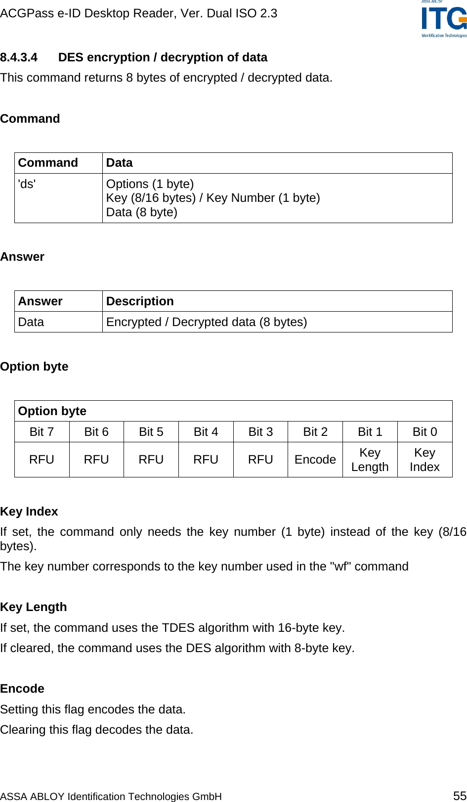
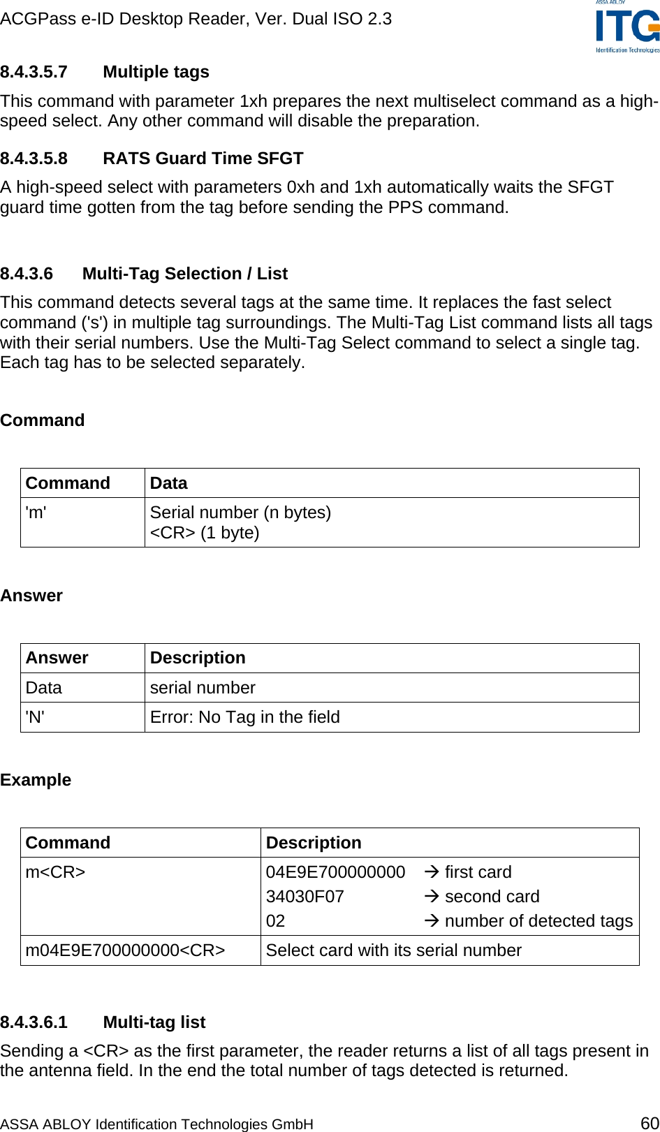
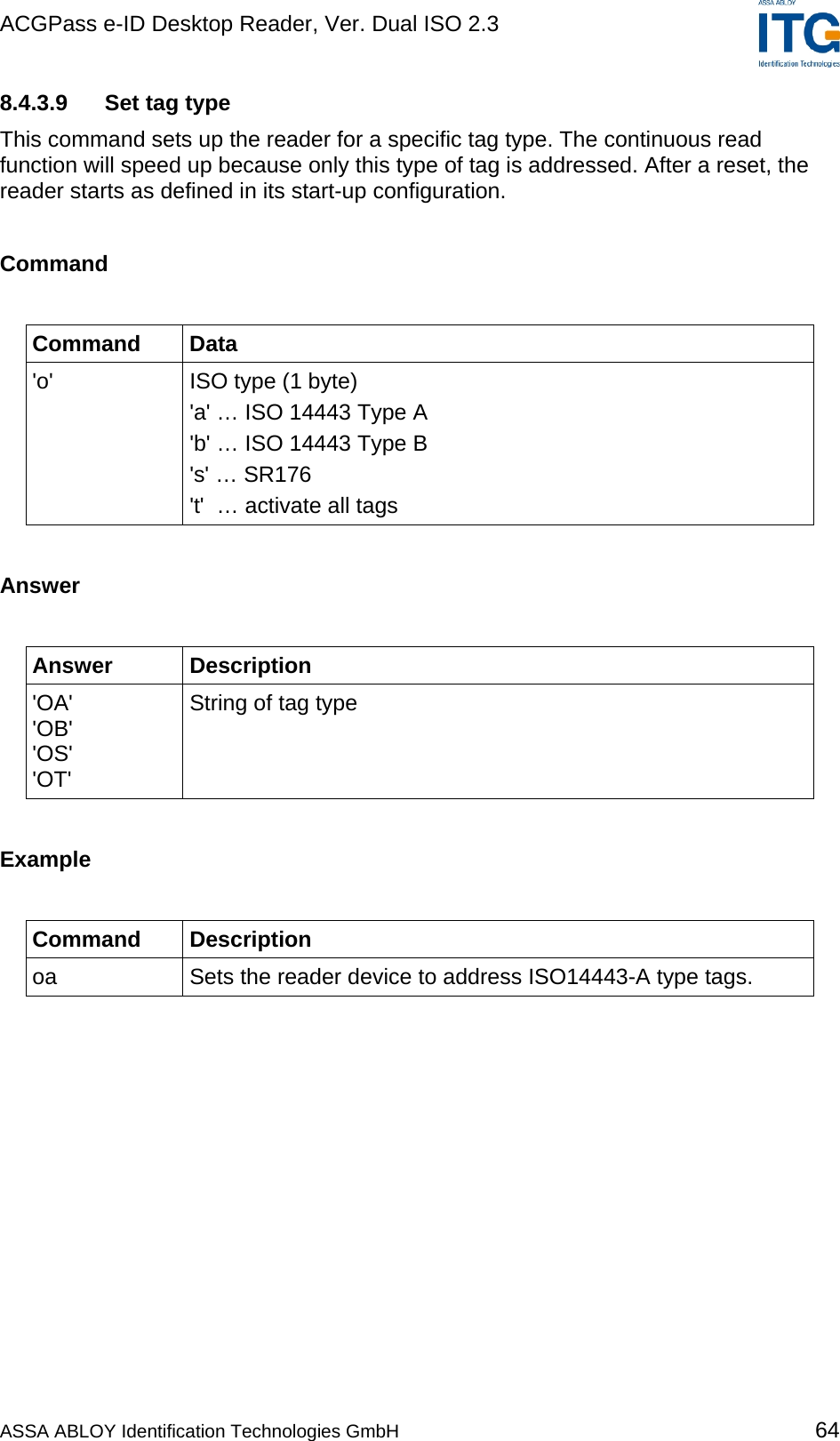
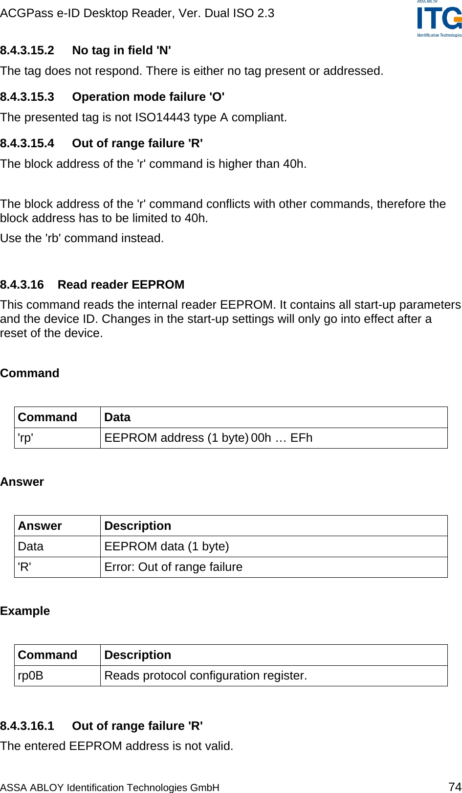
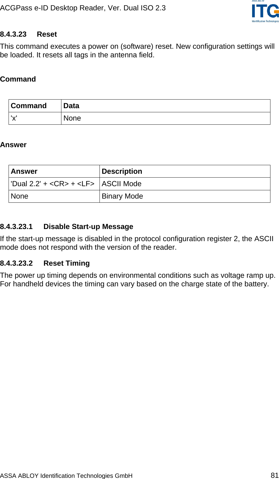
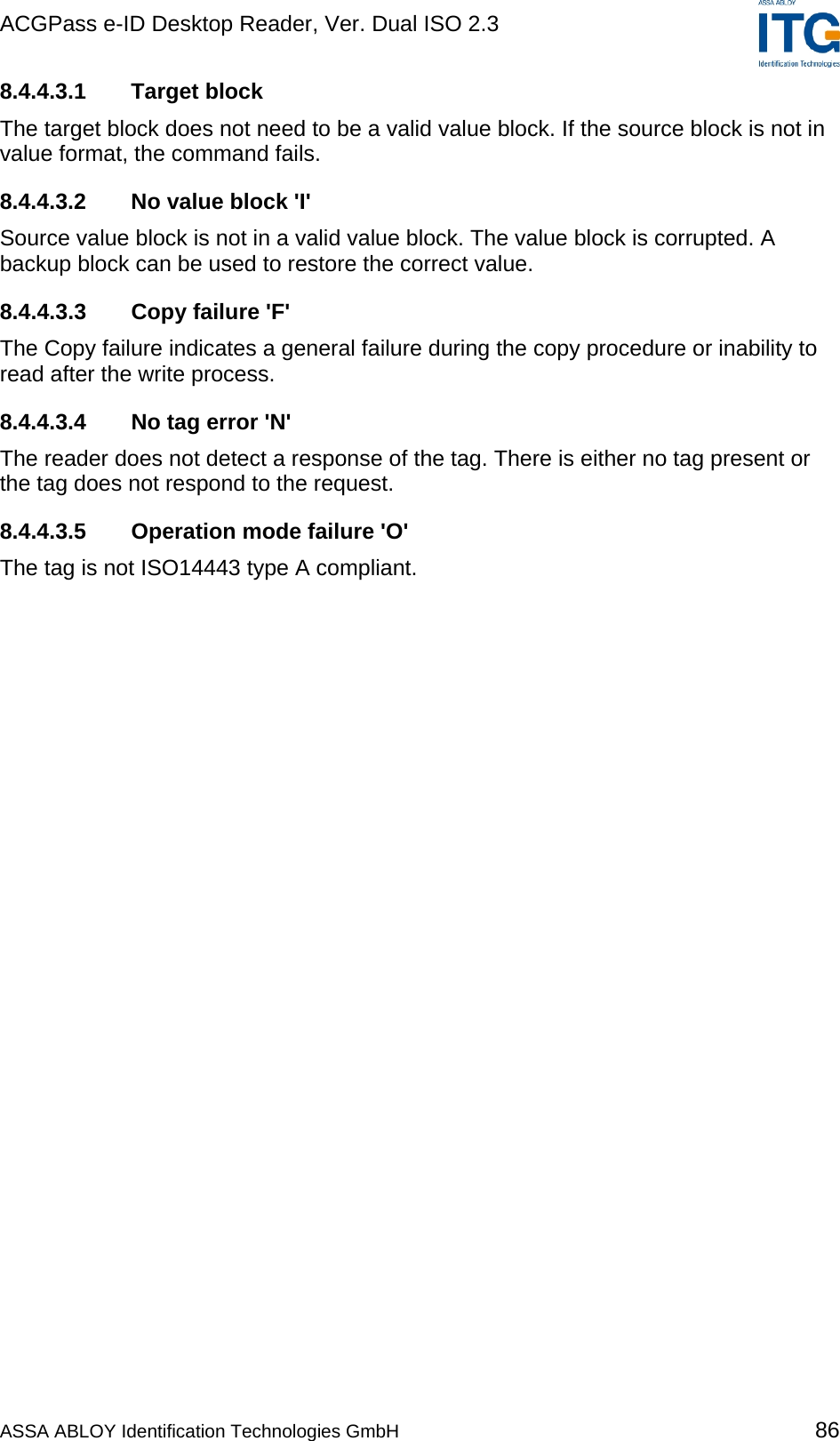
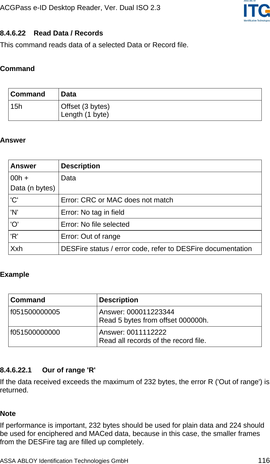
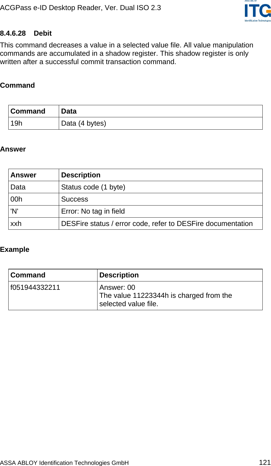
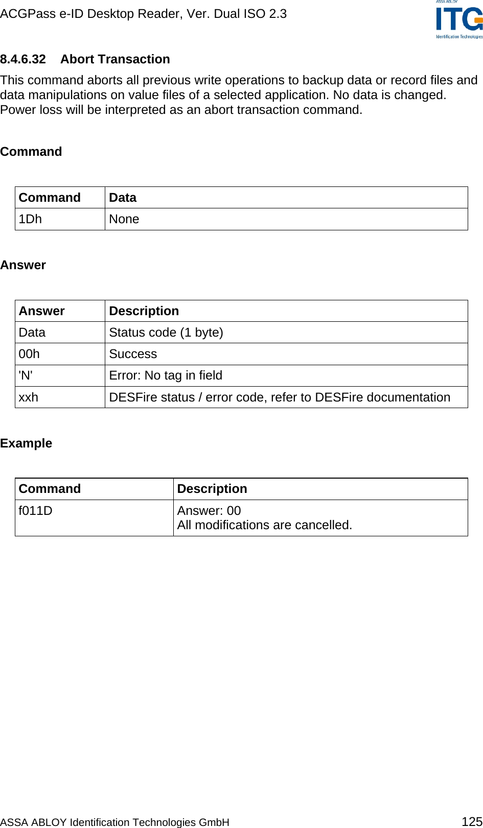
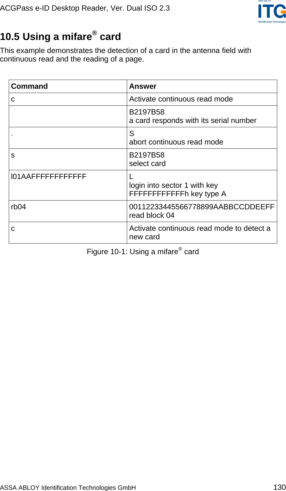
![ACGPass e-ID Desktop Reader, Ver. Dual ISO 2.3 8.3.4.8 Extend ID (default 0) If set, the reader extends the serial number of tags with additional bytes. ISO 14443 A tags (5/8/11 bytes transmitted) Tag type Serial number 1 byte 4 / 7 / 10 bytes Figure 8-6: ISO 14443 A Extended Serial number The tag type byte indicates the type of cascade level. Tag type Description 01h Cascade level 1 transponder 02h Cascade level 2 transponder 03h Cascade level 3 transponder Figure 8-7: ISO 14443 A tag type ISO 14443 B tags (12 bytes transmitted) Serial number Application data Protocol info CID 4 bytes 4 bytes 3 bytes 1 byte Figure 8-8: ISO 14443 B Extended Serial number For detailed description of Application Data, Protocol Info and CID, refer to the ISO 14443 documentation [1]. ASSA ABLOY Identification Technologies GmbH 41](https://usermanual.wiki/ASSALOY-Identification-Technologies/RDHS-0404D1-0X/User-Guide-795138-Page-42.png)
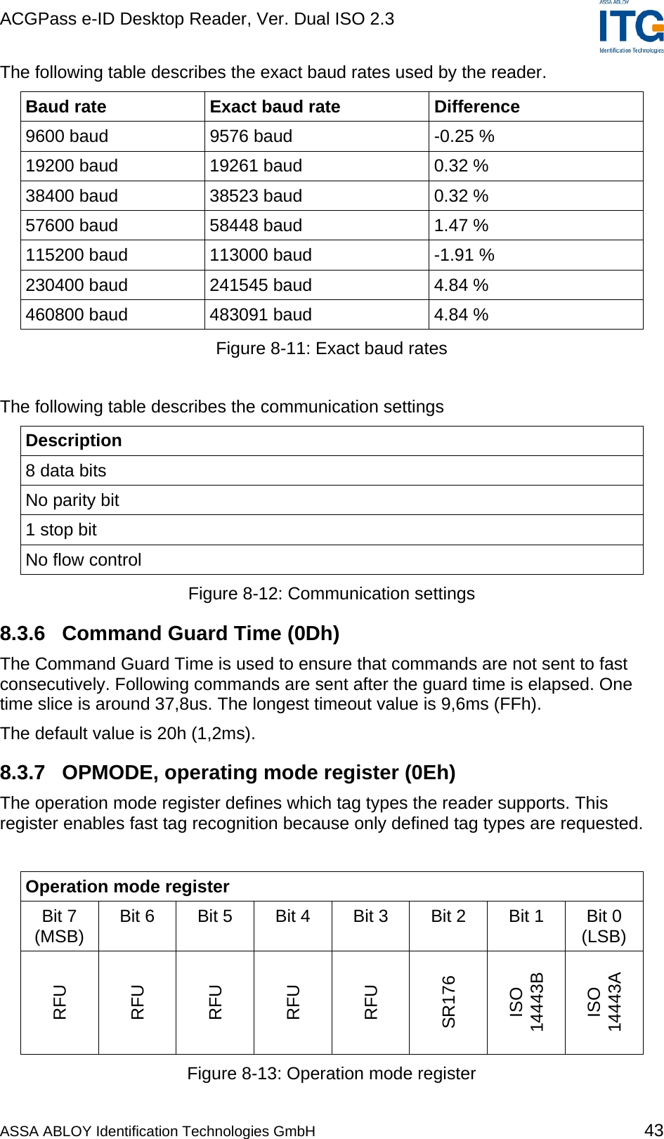
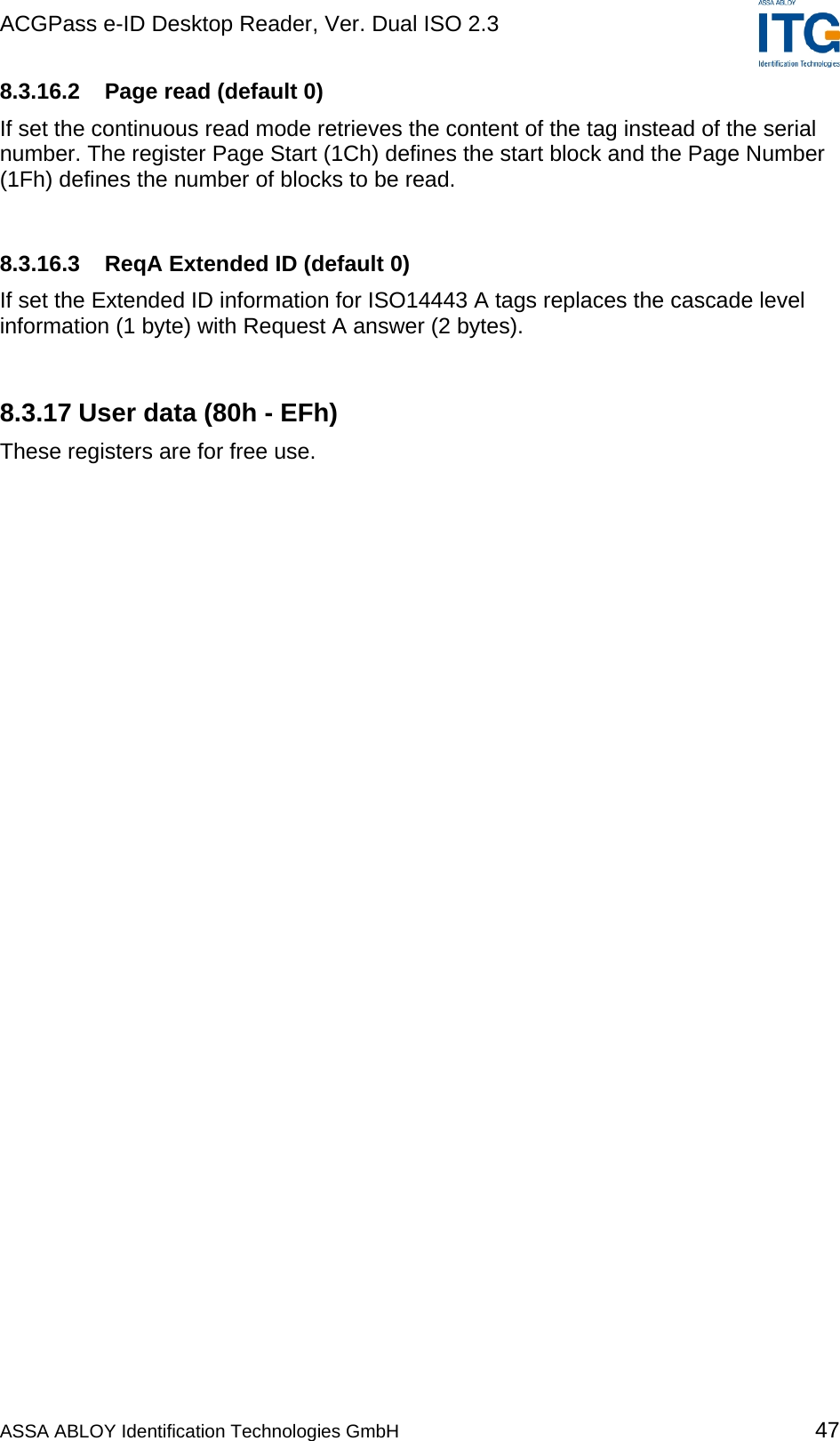

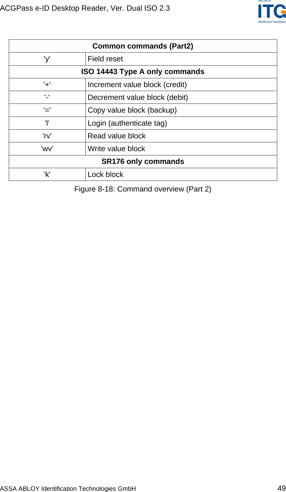
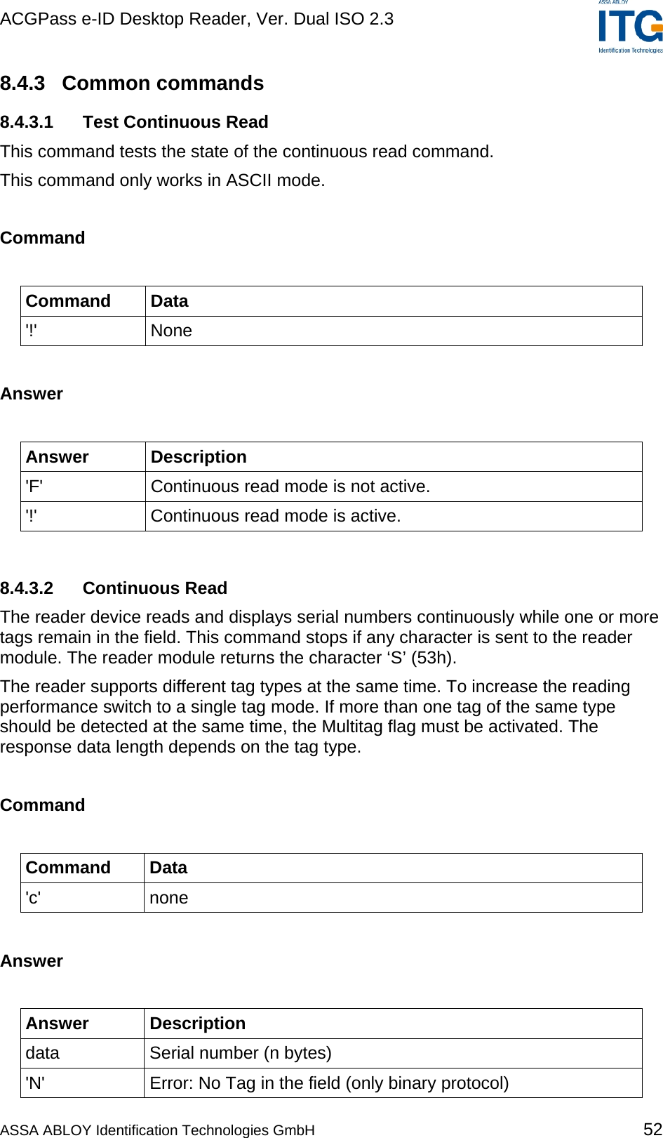
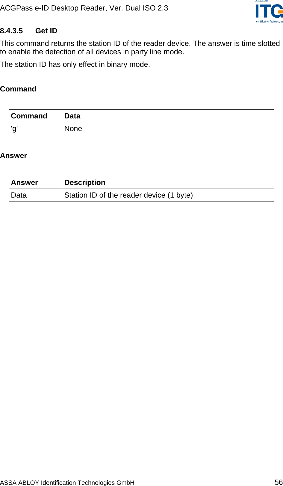

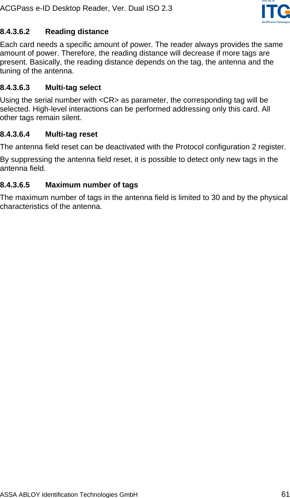
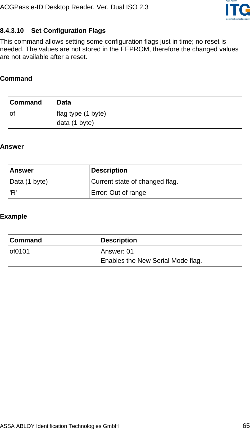
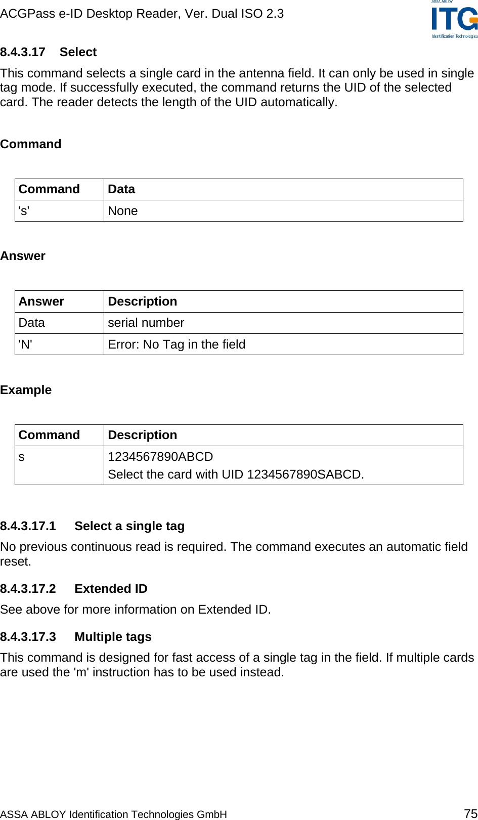
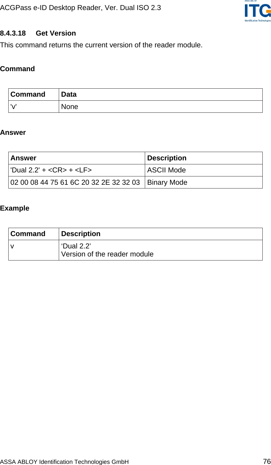
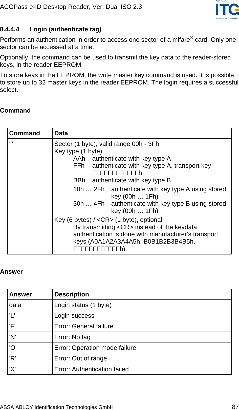
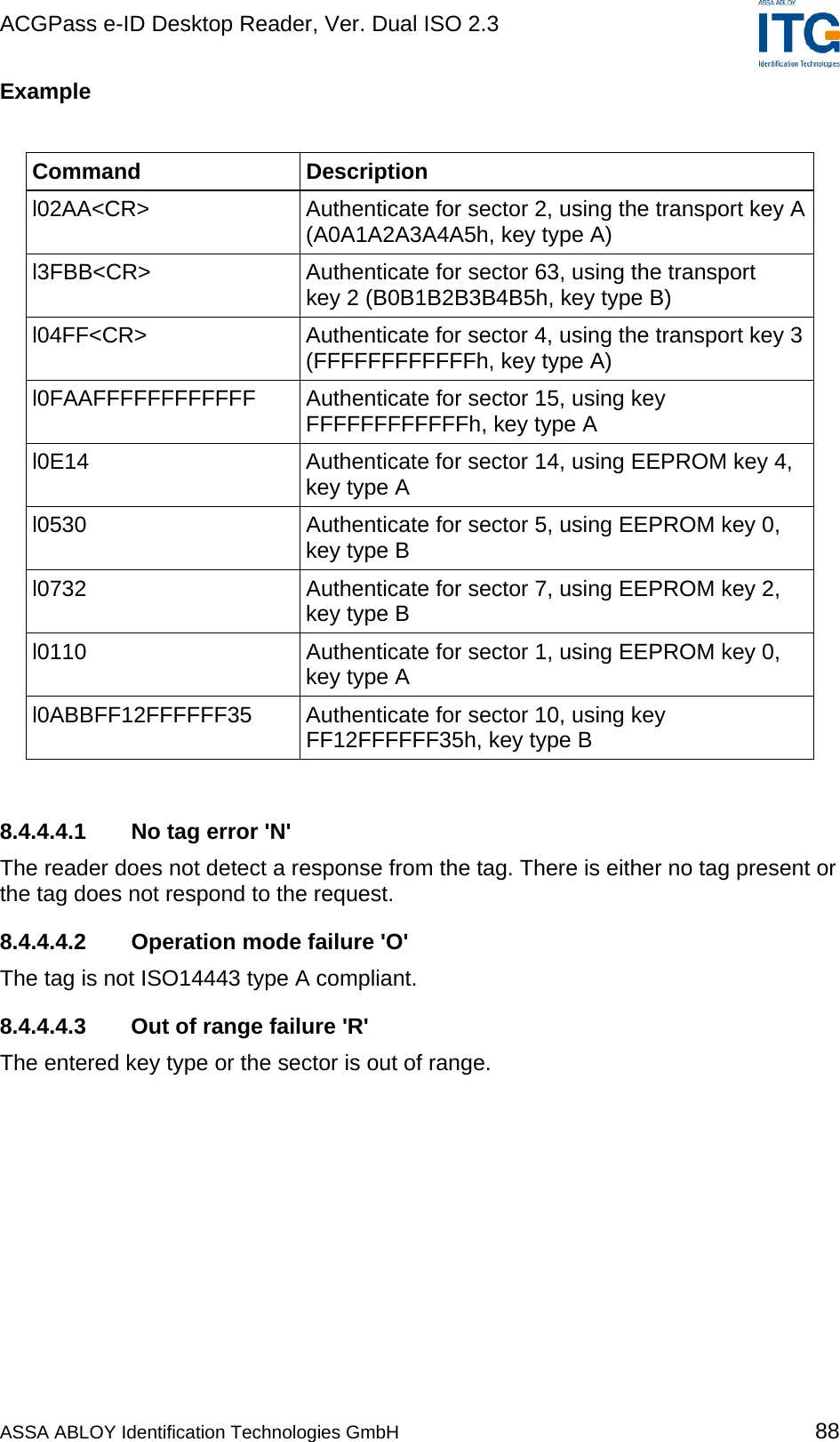
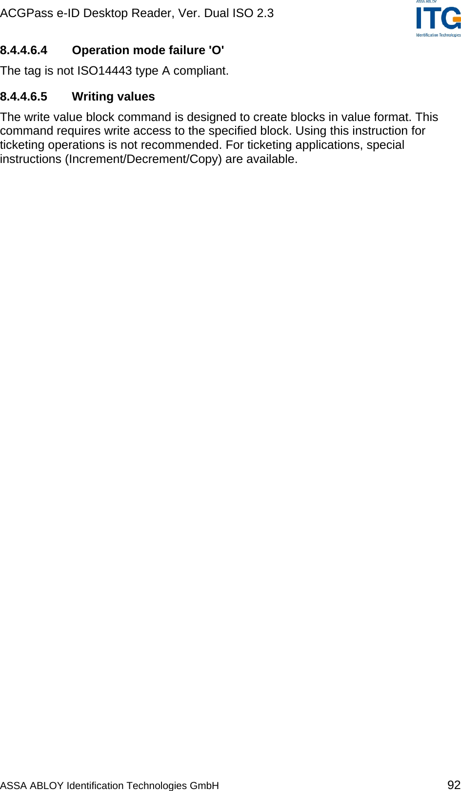
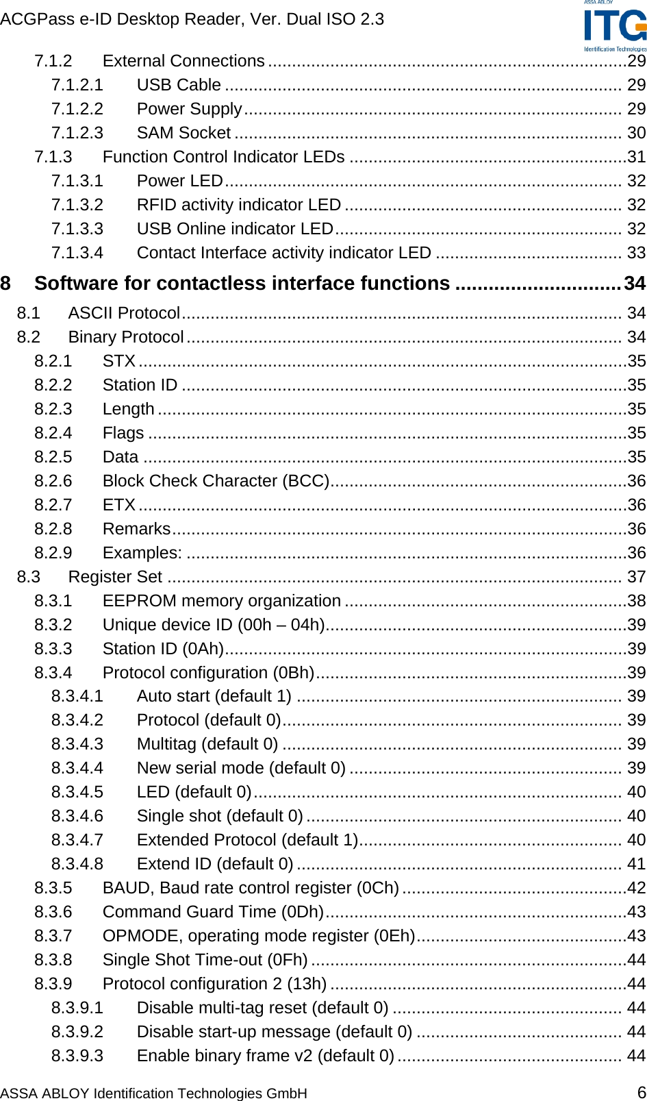
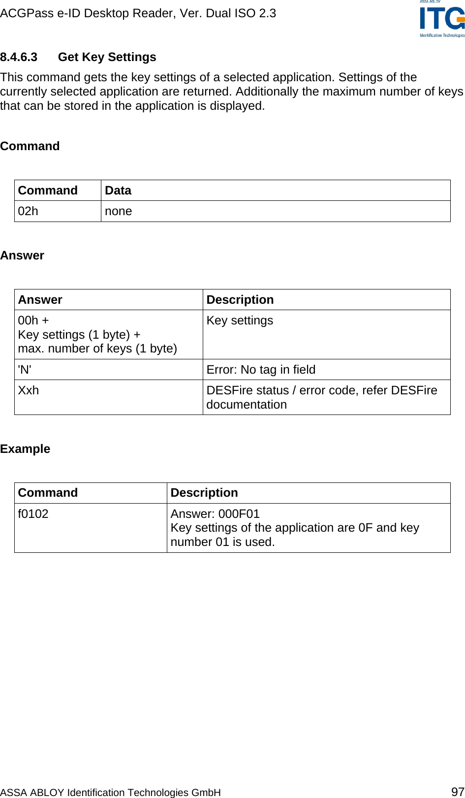
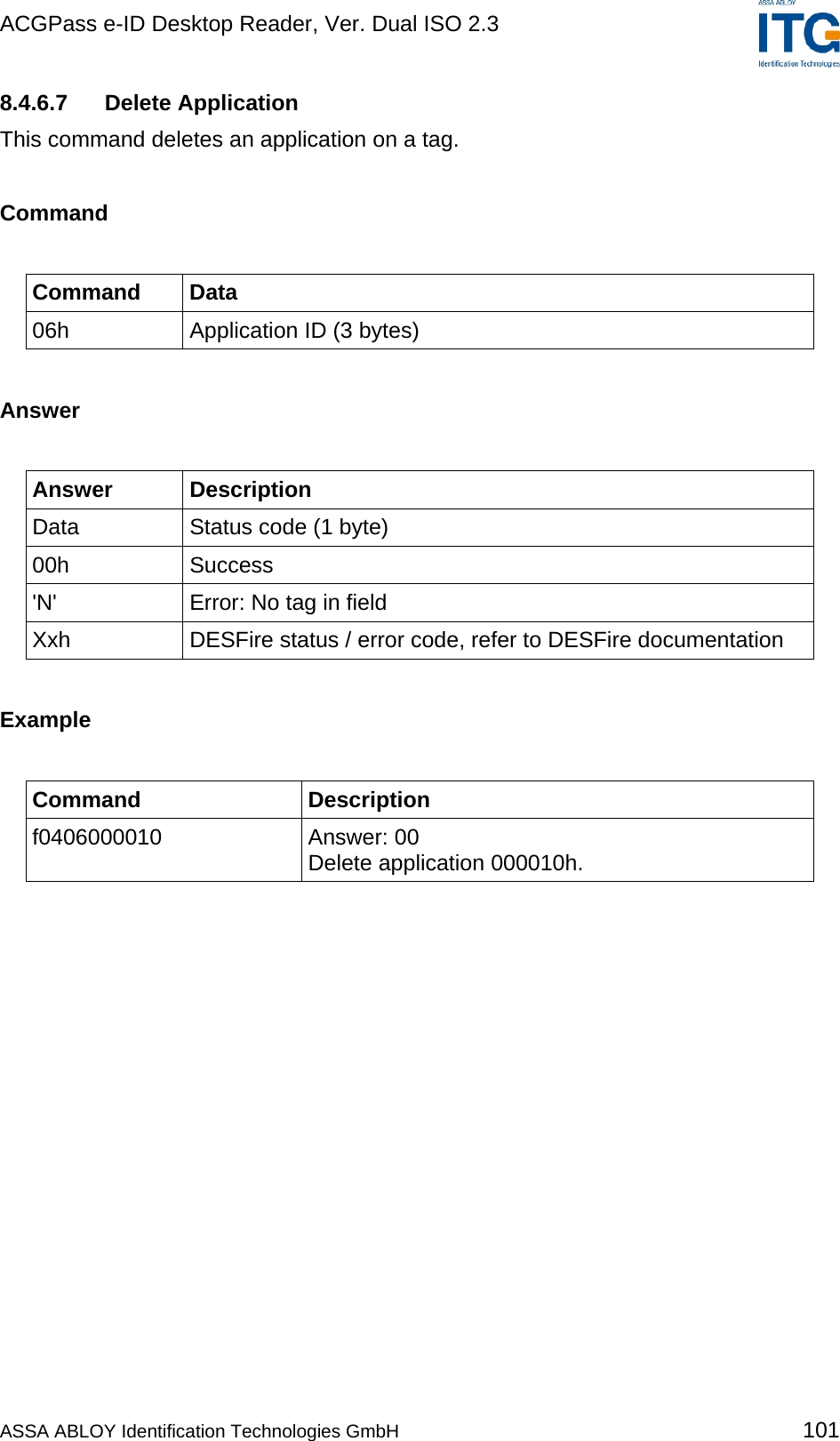
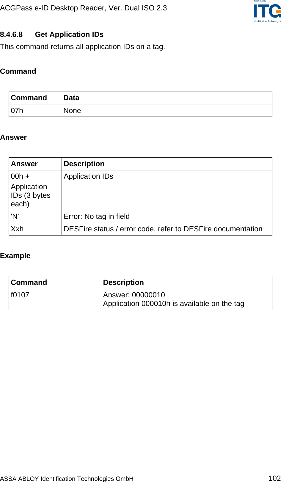
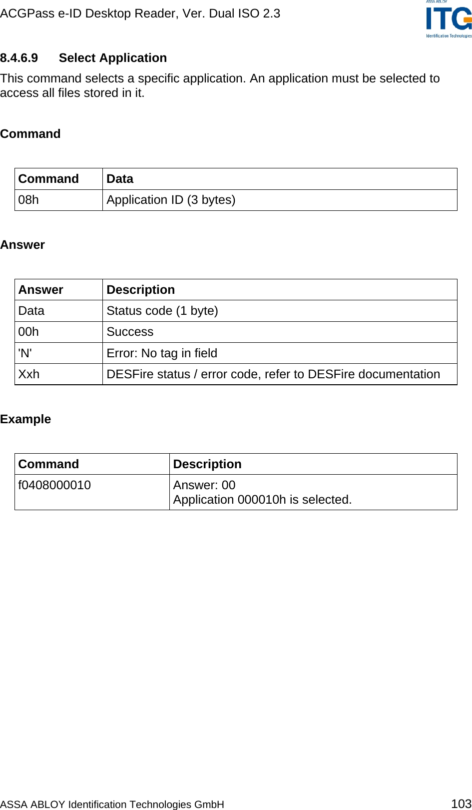
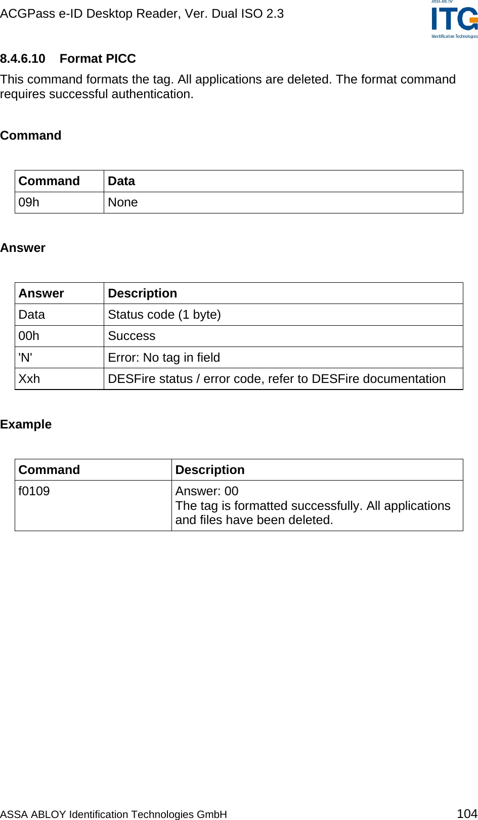
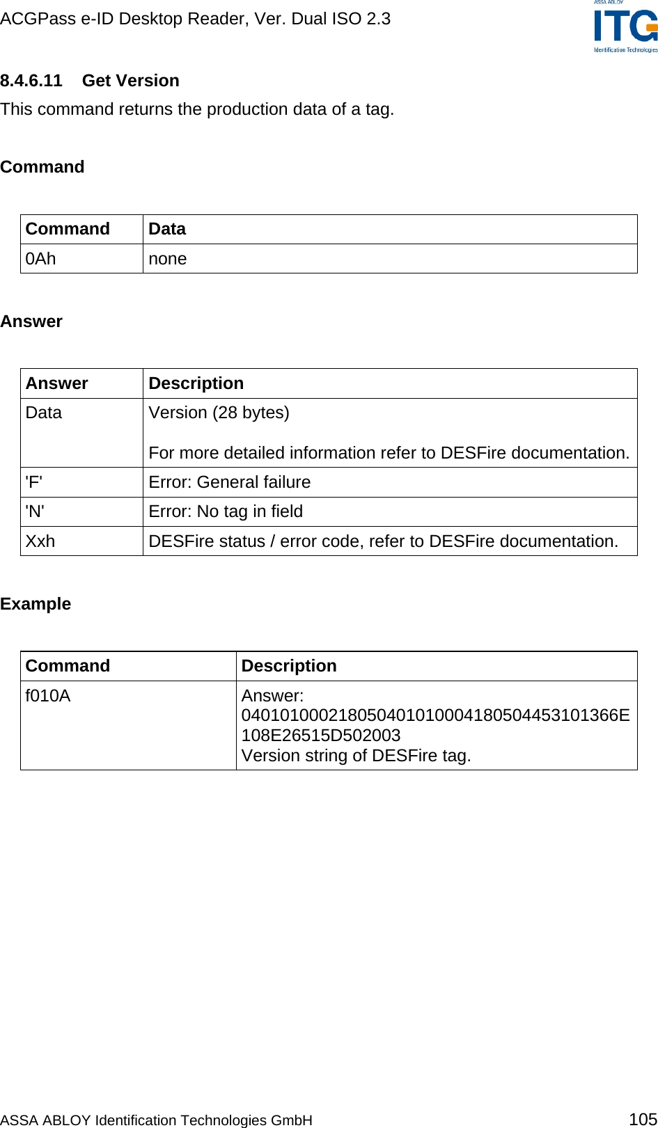
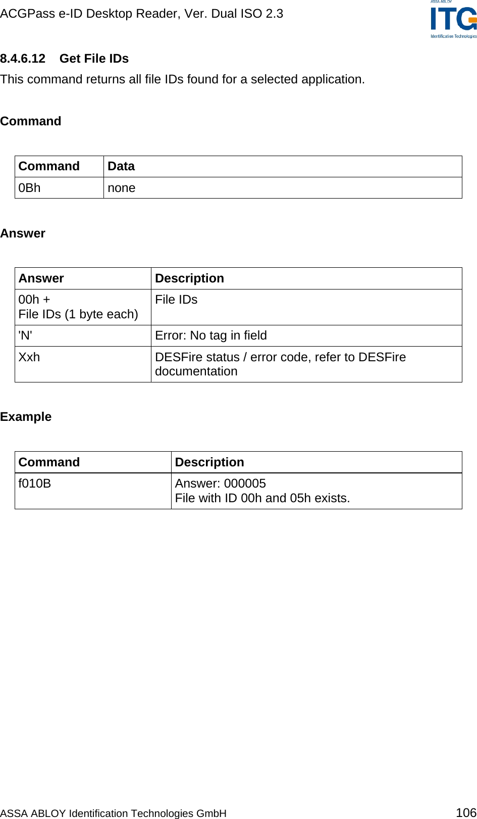
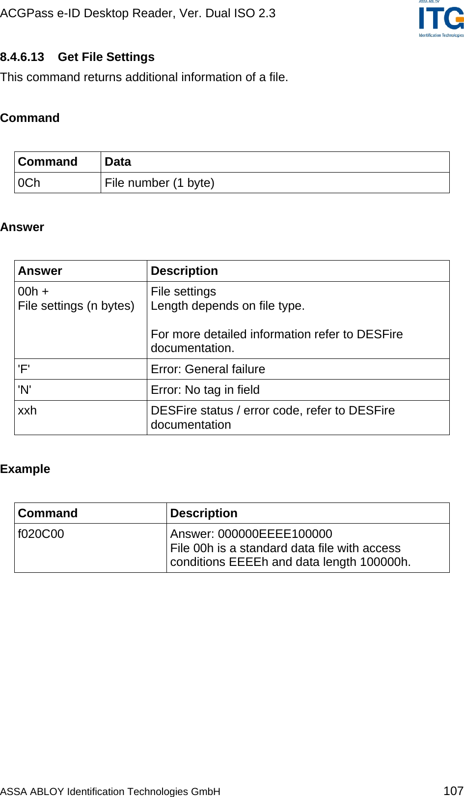
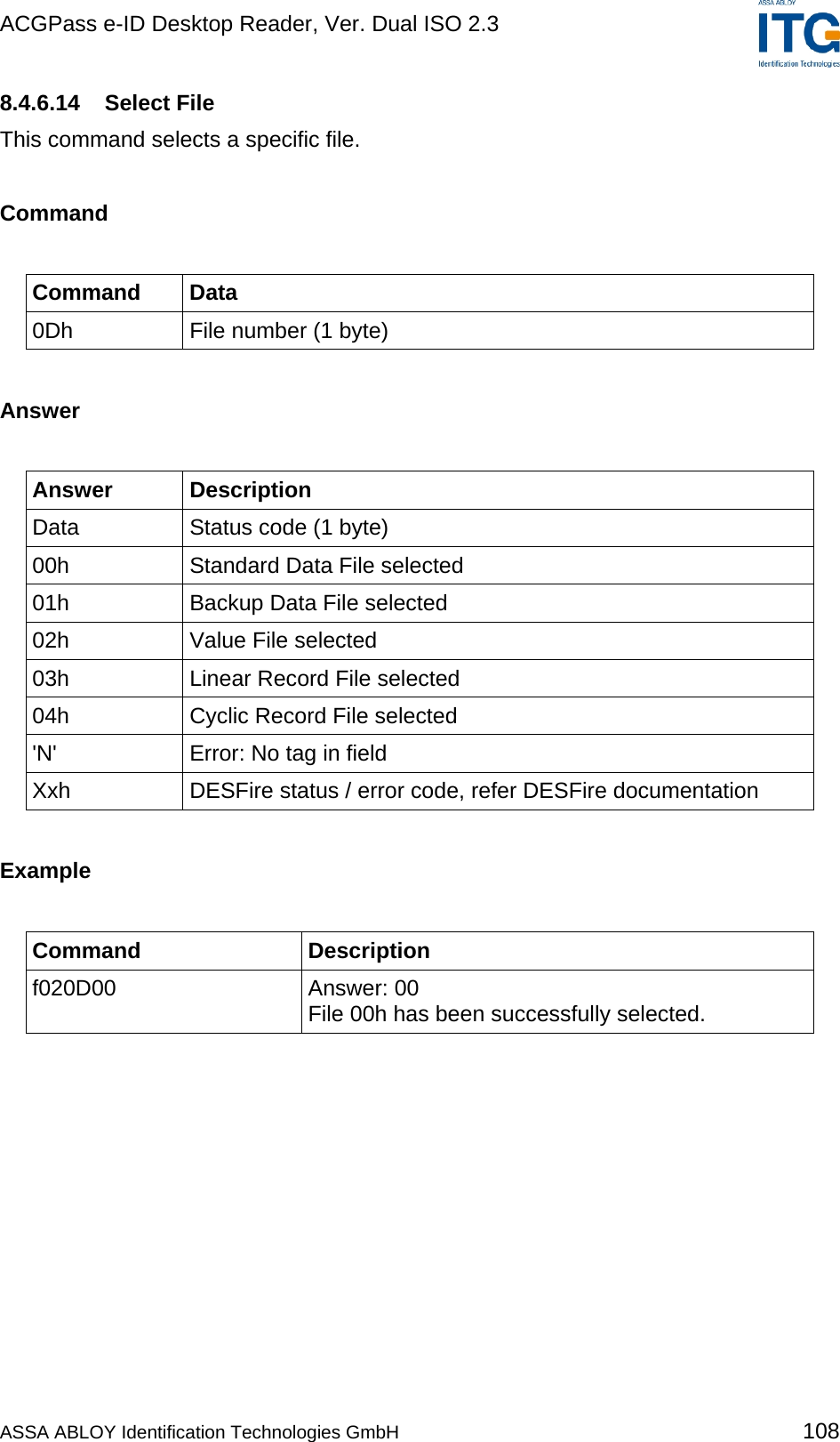
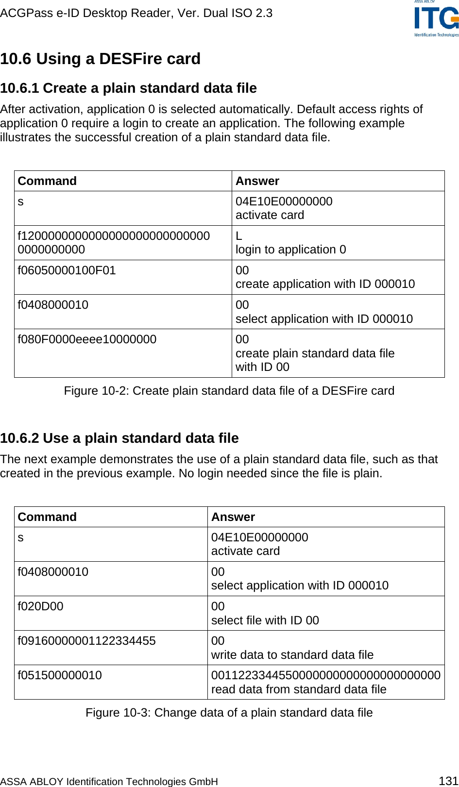
![ACGPass e-ID Desktop Reader, Ver. Dual ISO 2.3 8.4.6 DESFire command set This command set provides easy communication with DESFire tags. The reader handles all encryption and decryption automatically. The length byte includes all data and command bytes. For more information about DESFire, refer to DESFire documentation [2]. The DESFire command set is only available for ISO 14443 Type A tags; with other tags, the Error Code 'O' is returned. A DESFire command has the following syntax: Command Data 'f' Length byte (1 byte) DESFire Command Code (1 byte) Data (n bytes) Example Command Description f0107 Get Application IDs. f020D00 Select File 00h. All the following DESFire commands are listed without length byte. ASSA ABLOY Identification Technologies GmbH 94](https://usermanual.wiki/ASSALOY-Identification-Technologies/RDHS-0404D1-0X/User-Guide-795138-Page-95.png)
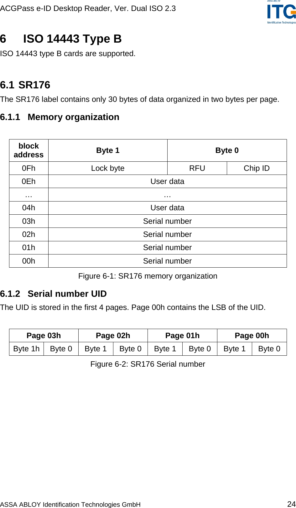
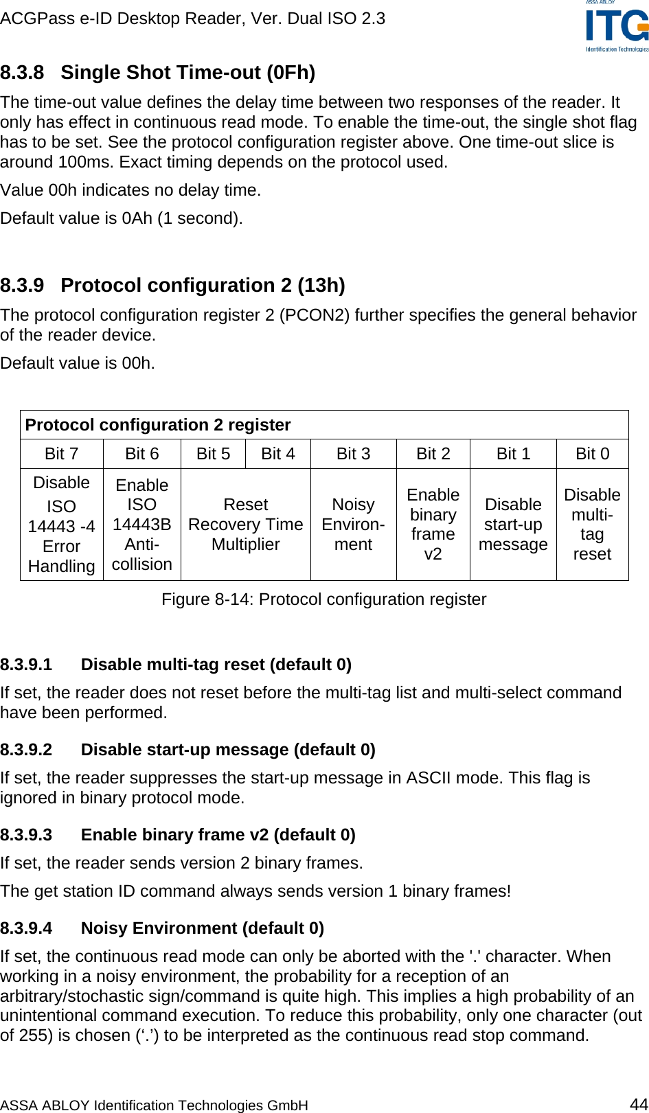
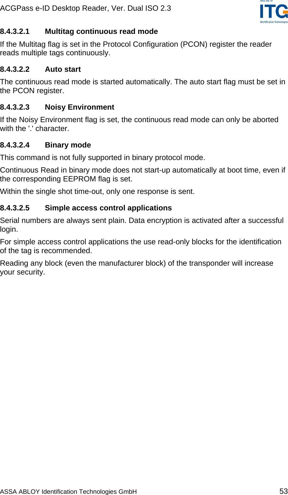
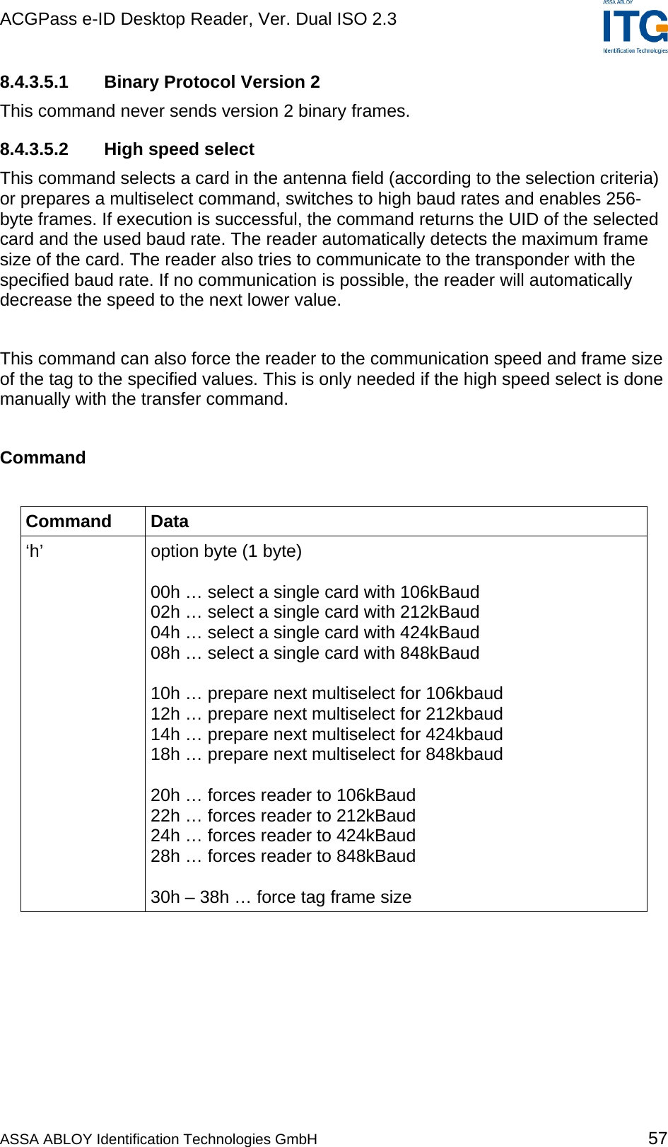
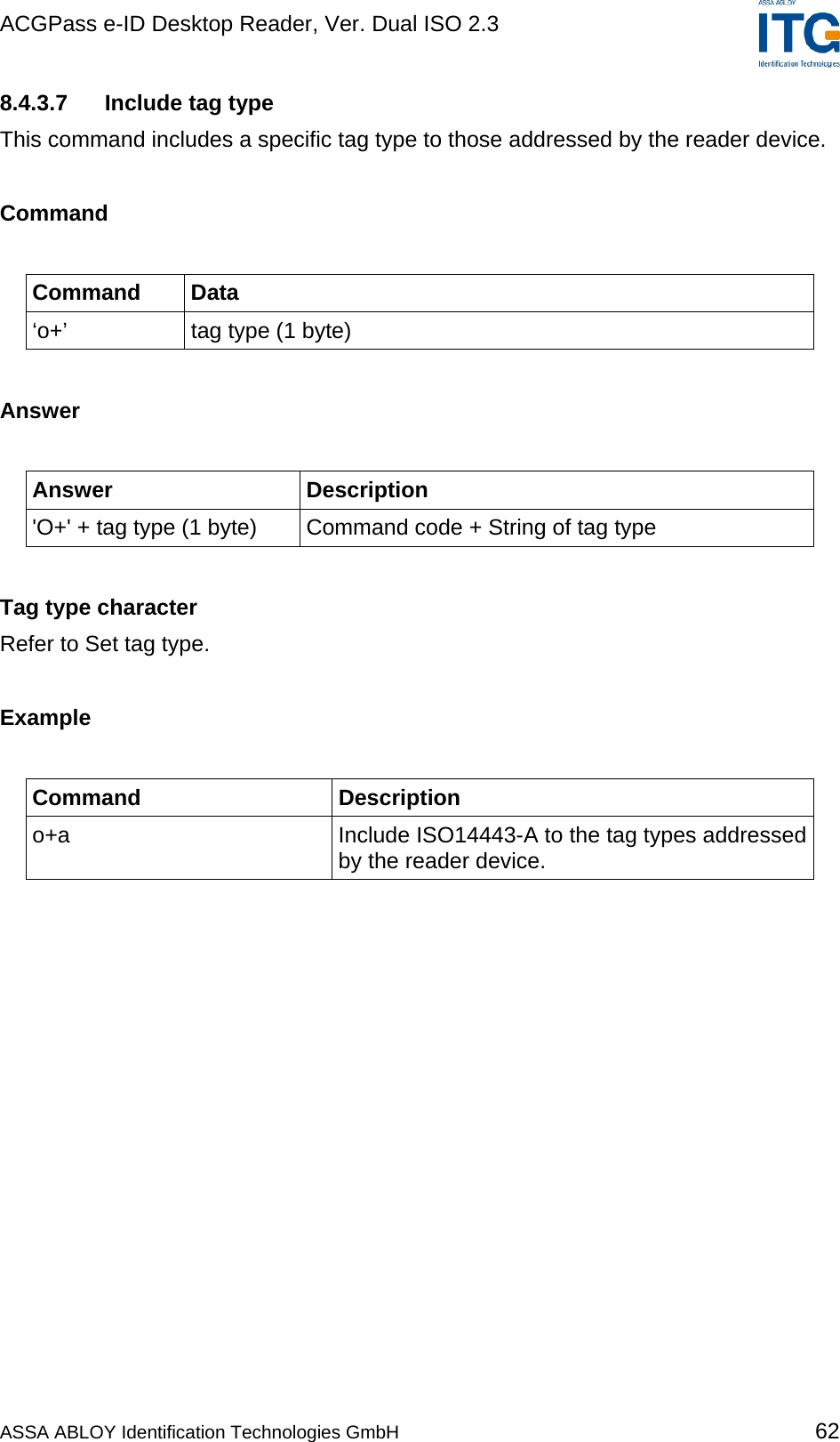
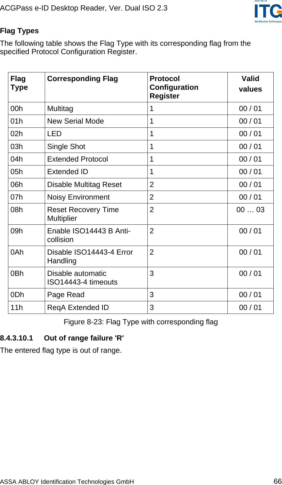
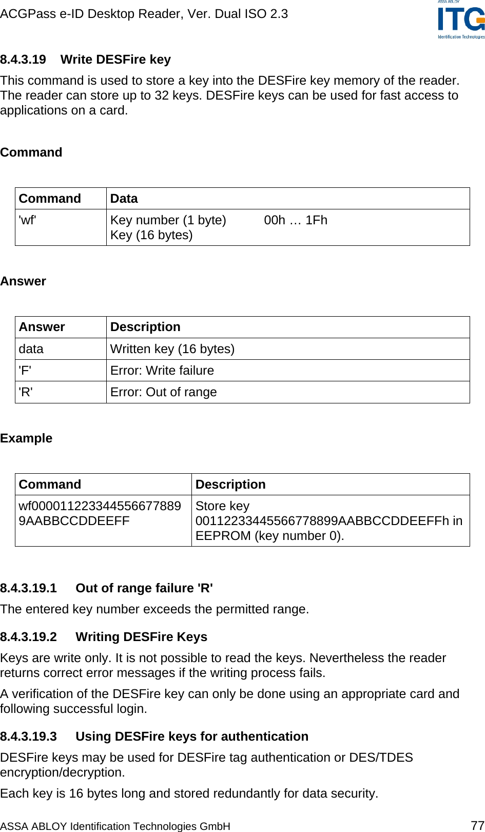
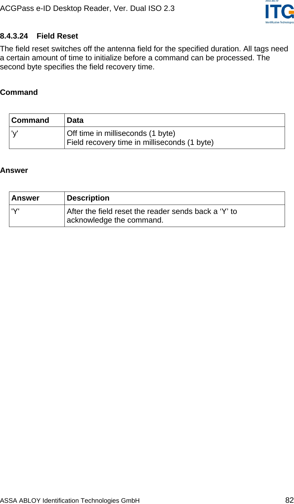
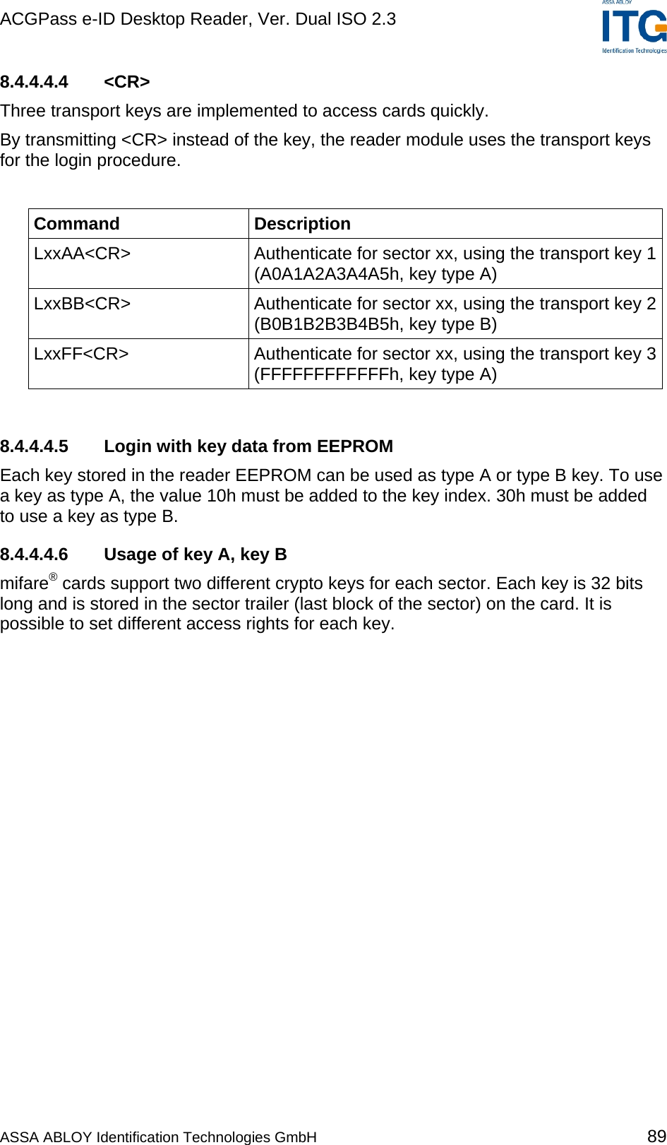
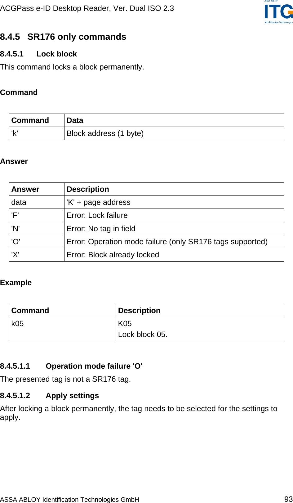
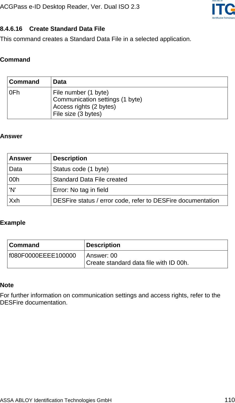
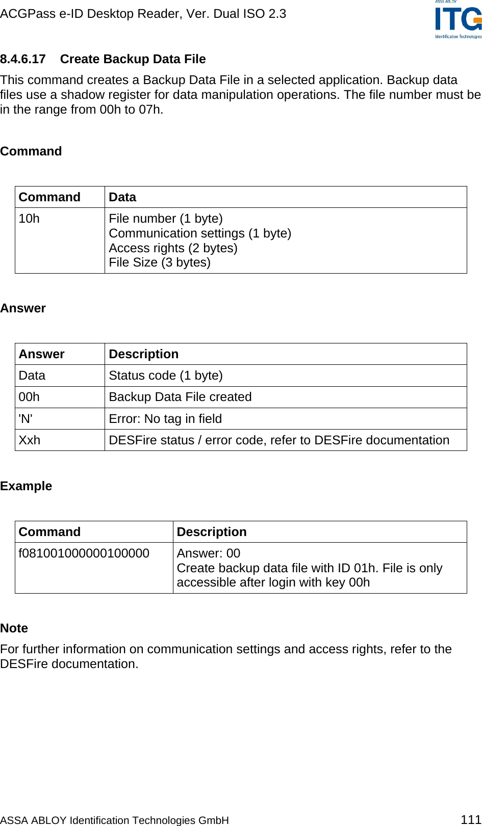
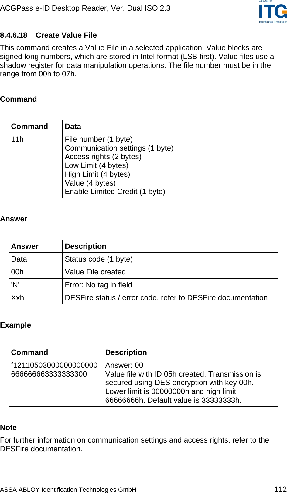
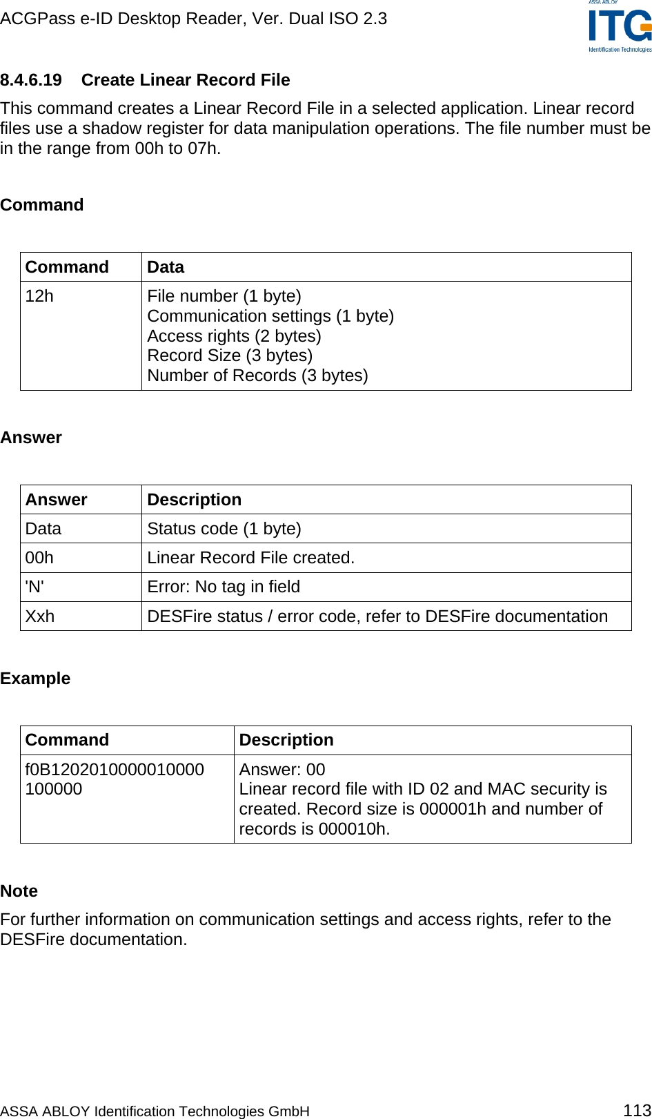
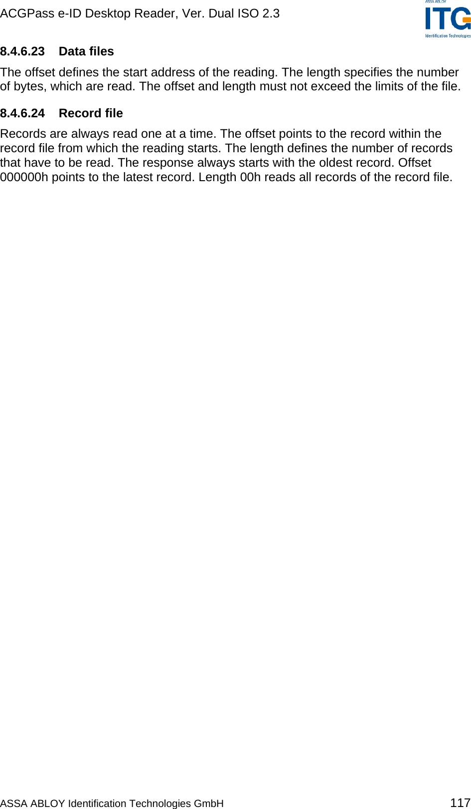
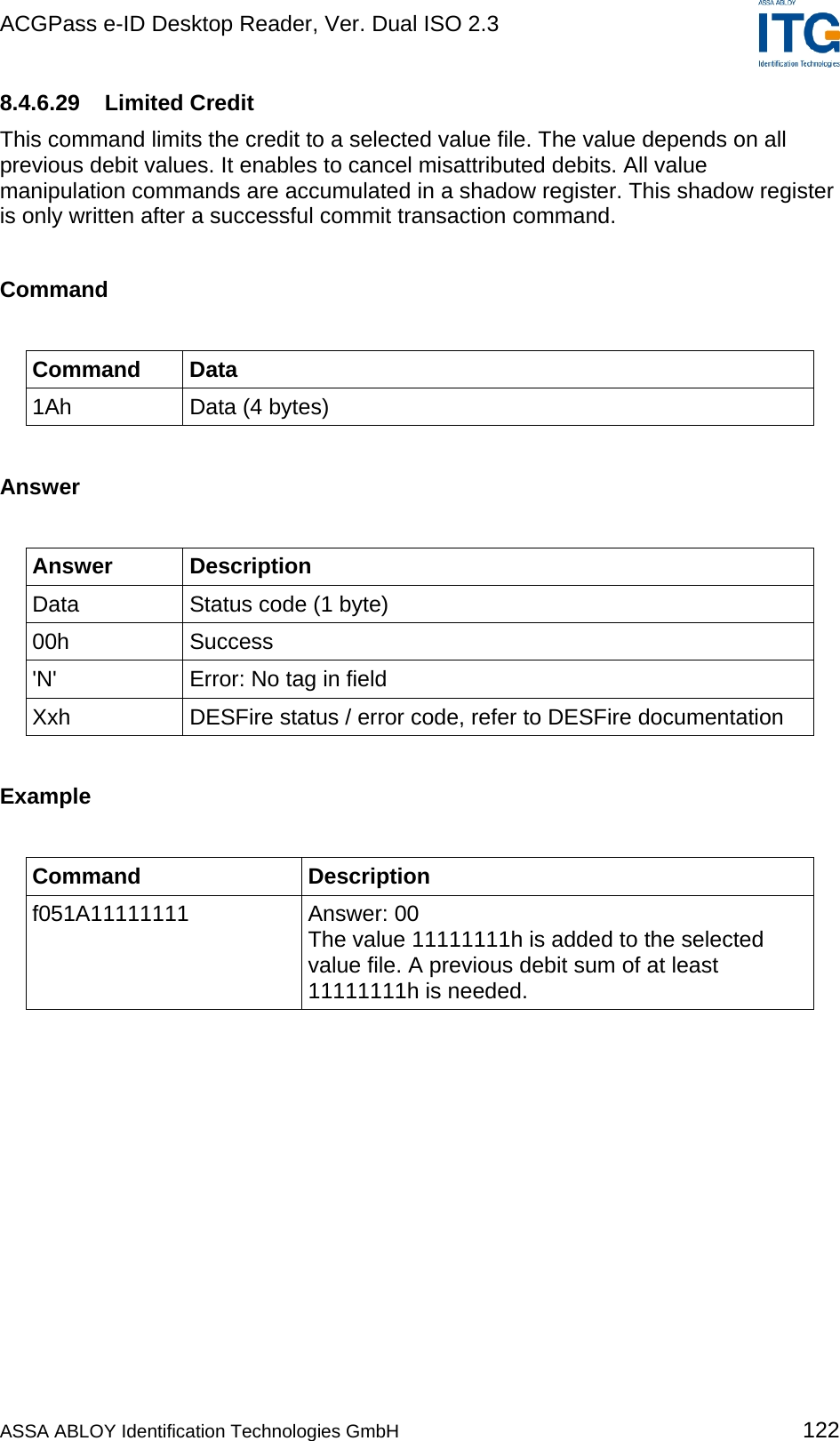
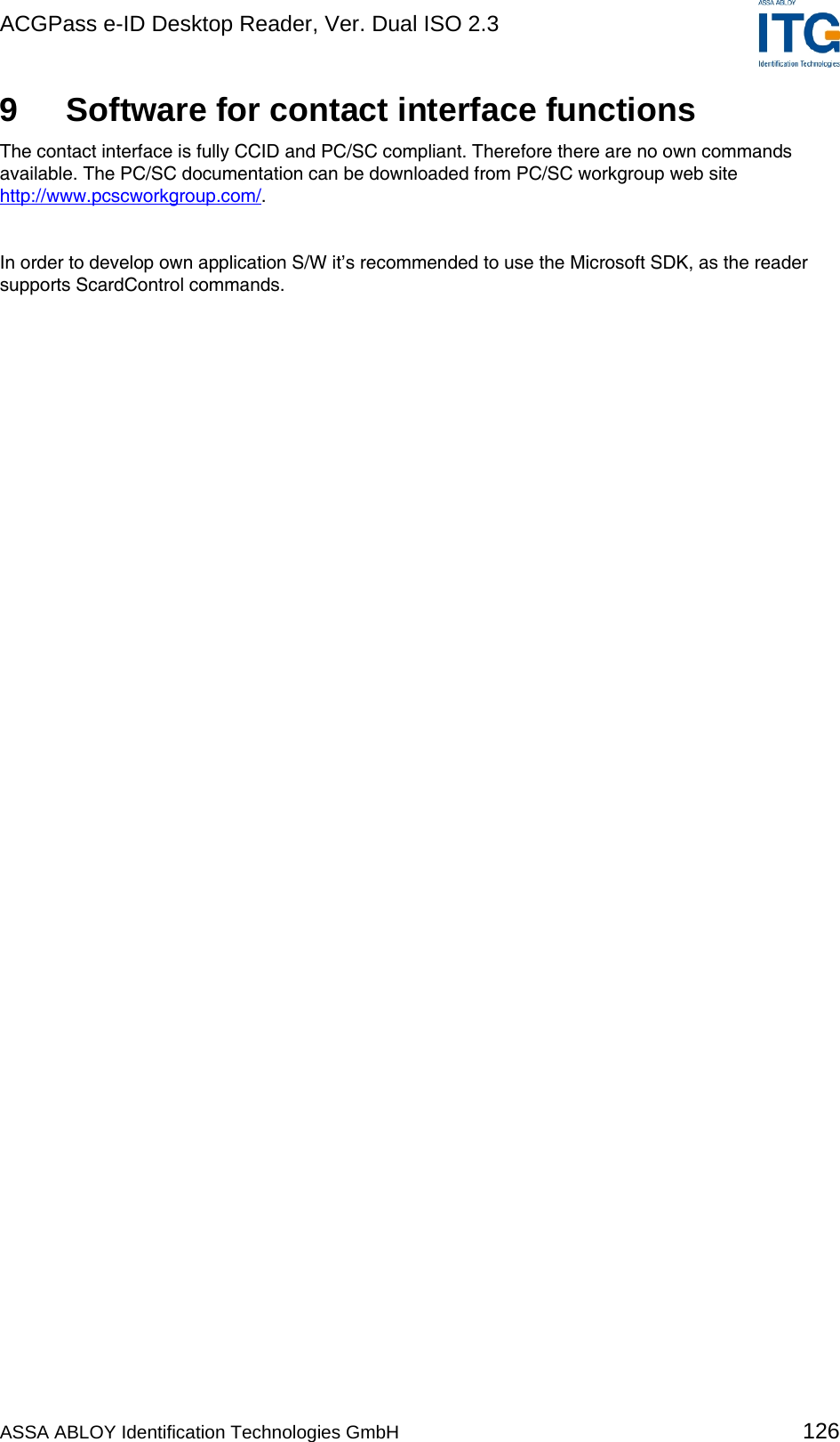
![ACGPass e-ID Desktop Reader, Ver. Dual ISO 2.3 8.4.6.15 Change File Settings This command changes the access rights of a selected file. Command Command Data 0Eh Communication settings (1 byte) Access rights (2 bytes) Answer Answer Description Data Status code (1 byte) 00h Standard Data File selected 'N' Error: No tag in field 'O' Error: No file selected Xxh DESFire status / error code, refer to DESFire documentation Example Command Description f040E010000 Answer: 00 Sets file to MAC secured with key 0000h. Note For further information on communication settings and access rights, refer to the DESFire documentation. [2] ASSA ABLOY Identification Technologies GmbH 109](https://usermanual.wiki/ASSALOY-Identification-Technologies/RDHS-0404D1-0X/User-Guide-795138-Page-110.png)


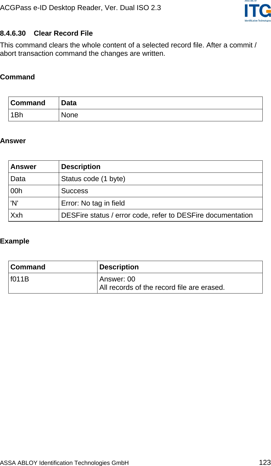
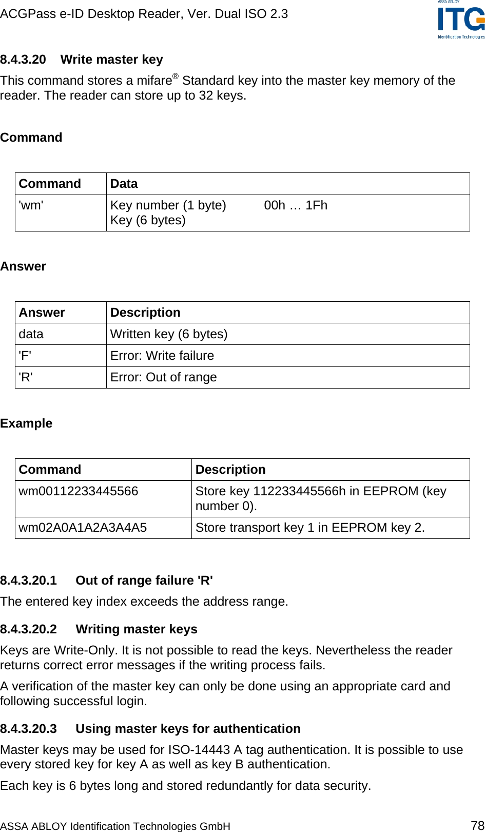
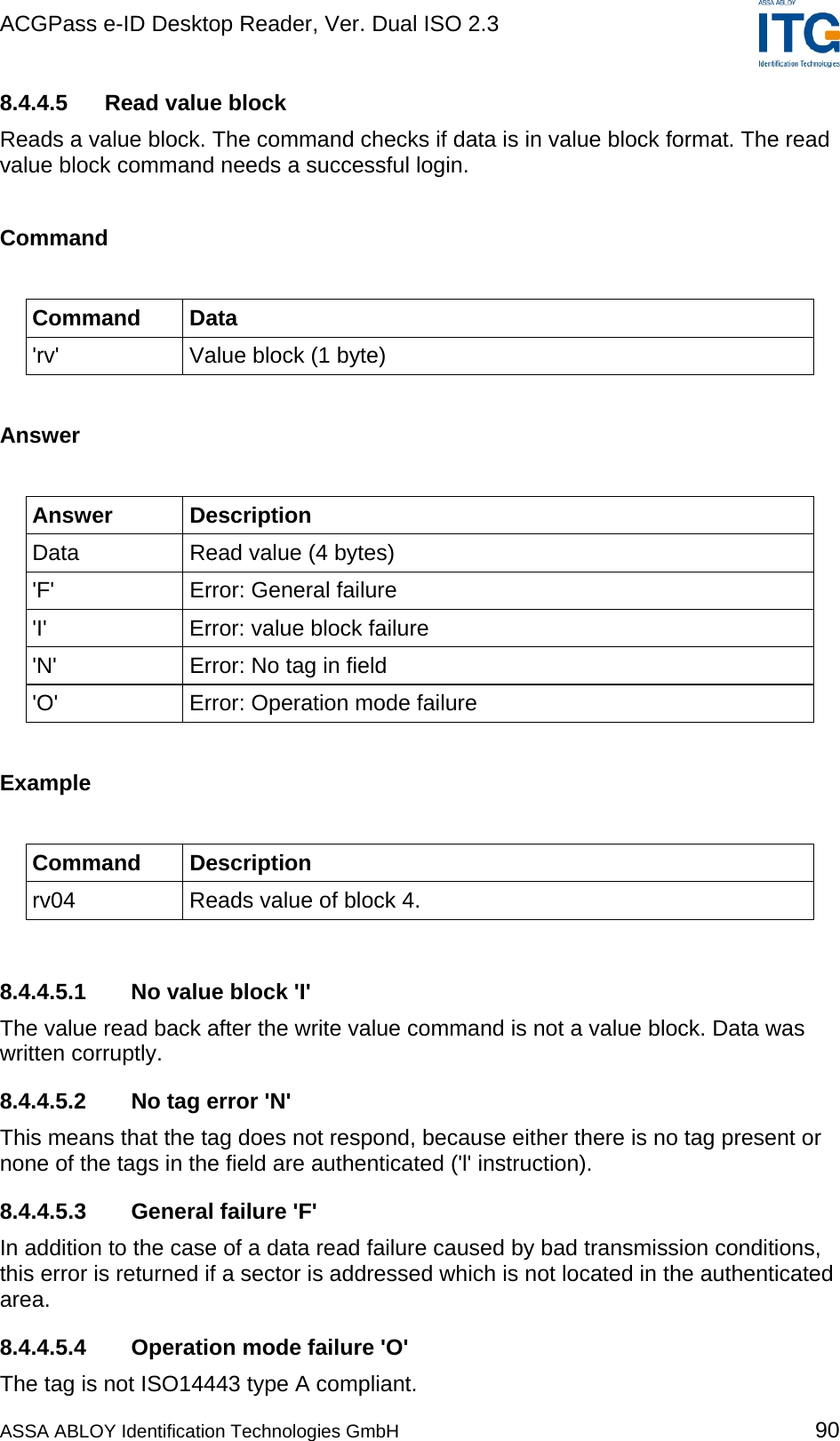
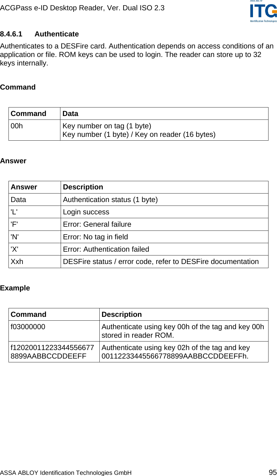
![ACGPass e-ID Desktop Reader, Ver. Dual ISO 2.3 11 References [1] ISO/IEC 14443 Part 1-4, Identification Cards – Contact less integrated circuit(s) cards – Proximity cards [2] DESFire Documentation, Philips, http://www.semiconductors.philips.com [3] Data Encryption Standard (DES), FIPS PUB 46-3, Reaffirmed 1995 October 25 [4] ASSA ABLOY ITG Antenna Design Guide [5] Philips; Application Note, mifare® & I-Code, Micore Reader IC family Directly Matched Antenna Design ASSA ABLOY Identification Technologies GmbH 134](https://usermanual.wiki/ASSALOY-Identification-Technologies/RDHS-0404D1-0X/User-Guide-795138-Page-135.png)
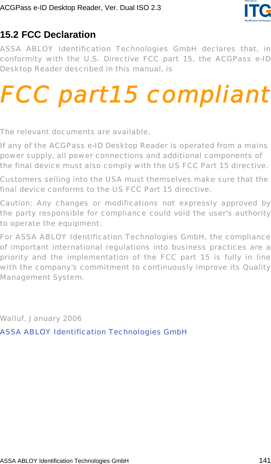
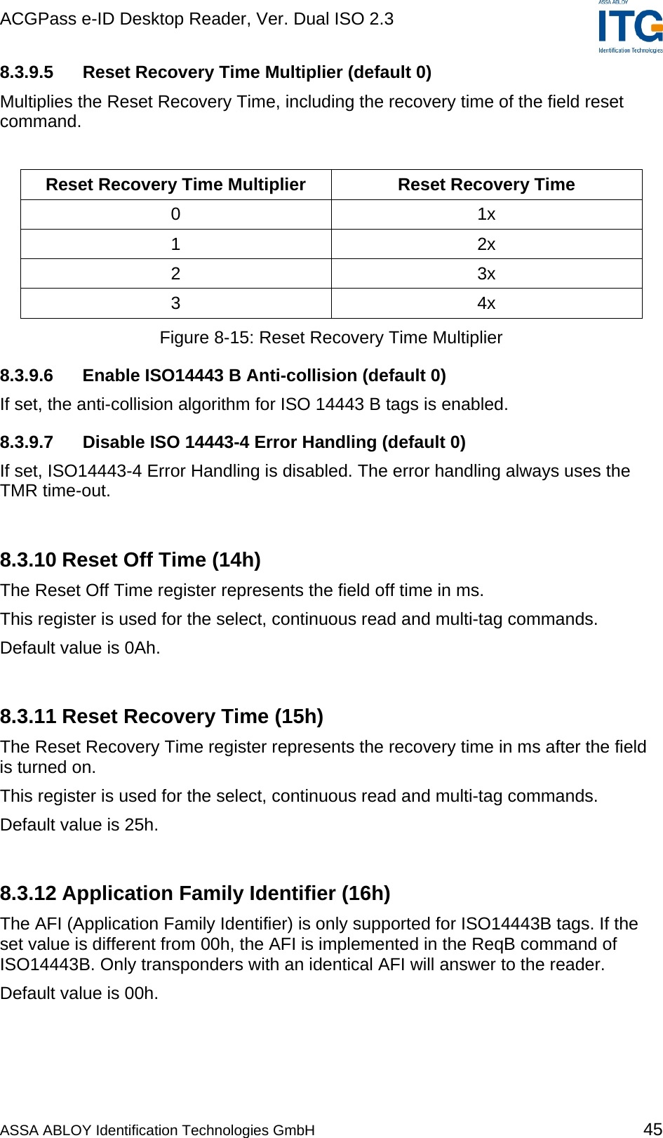
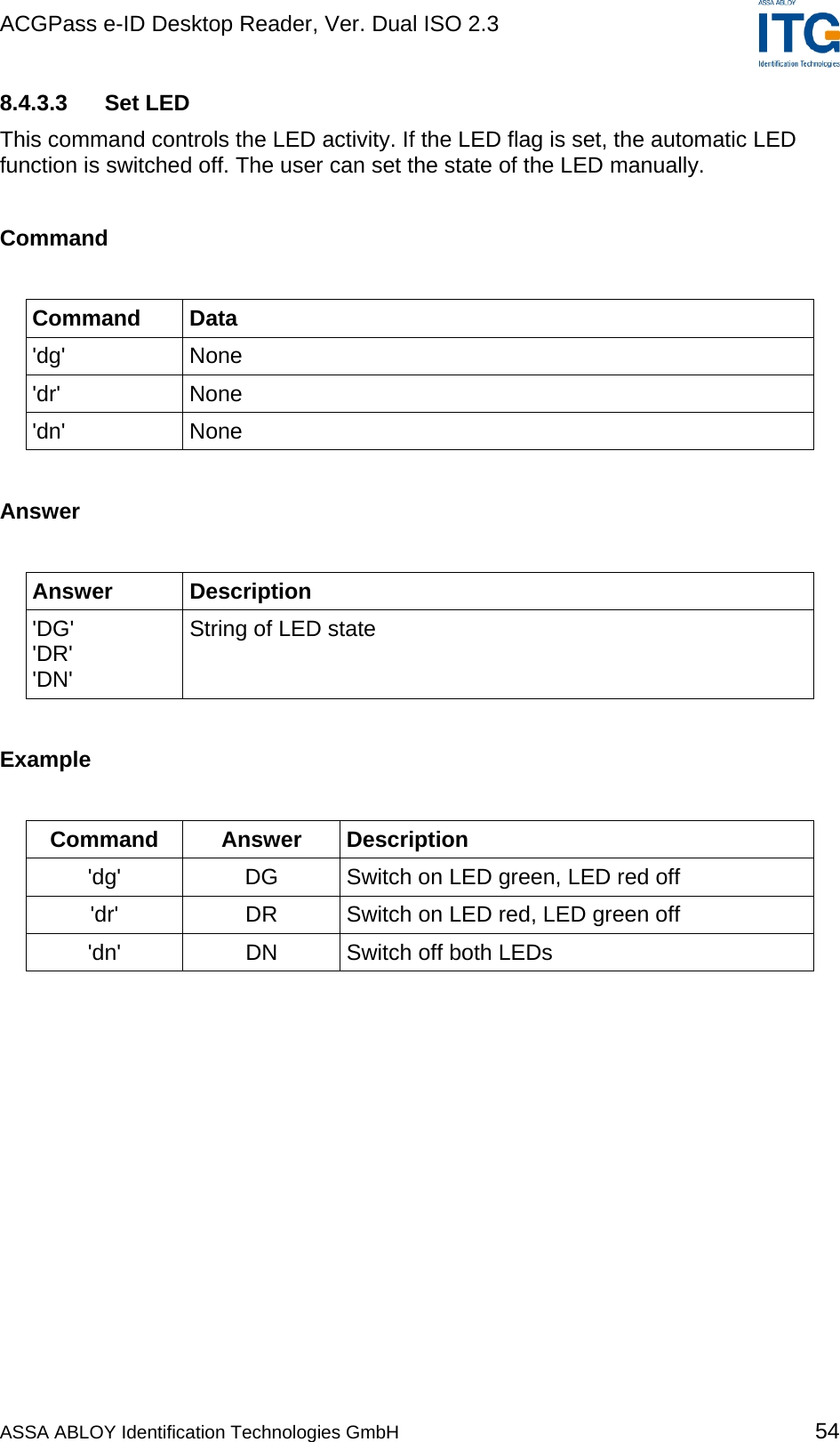
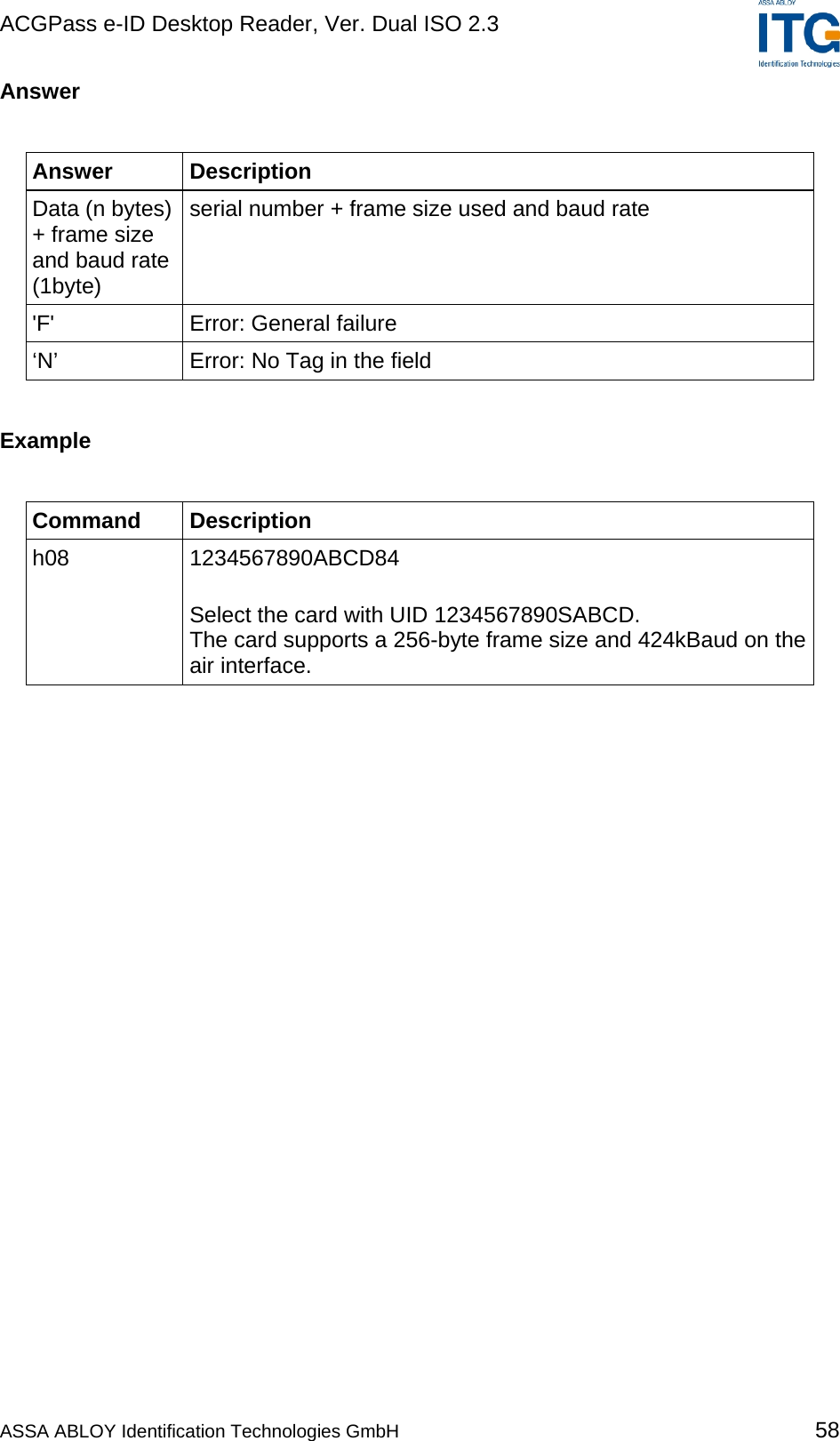
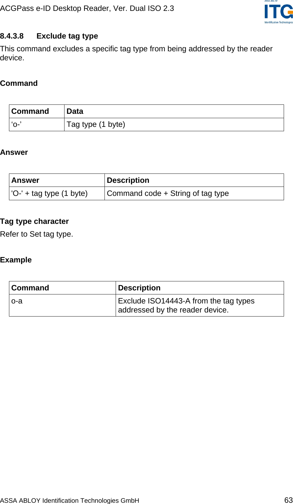
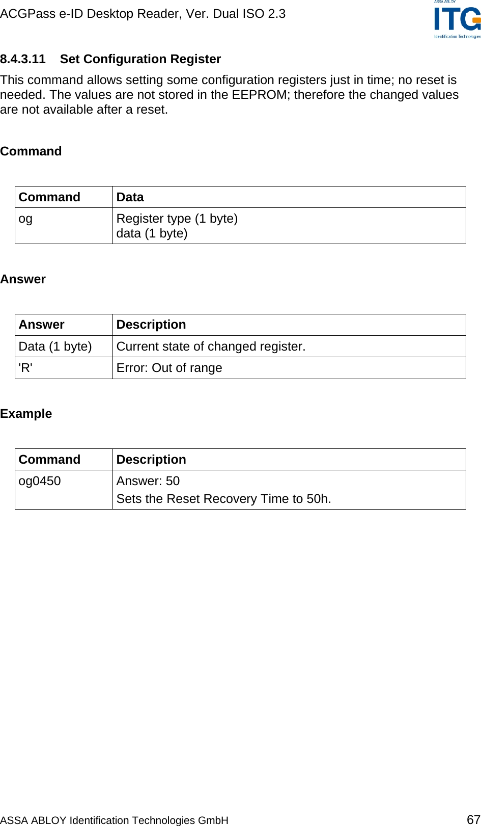
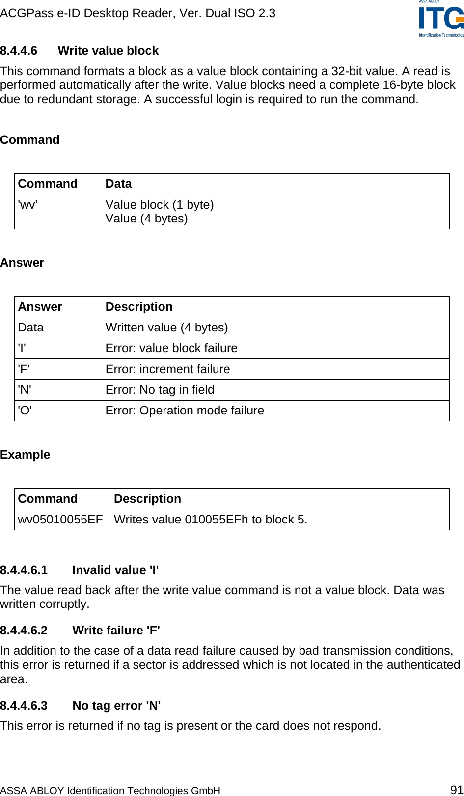
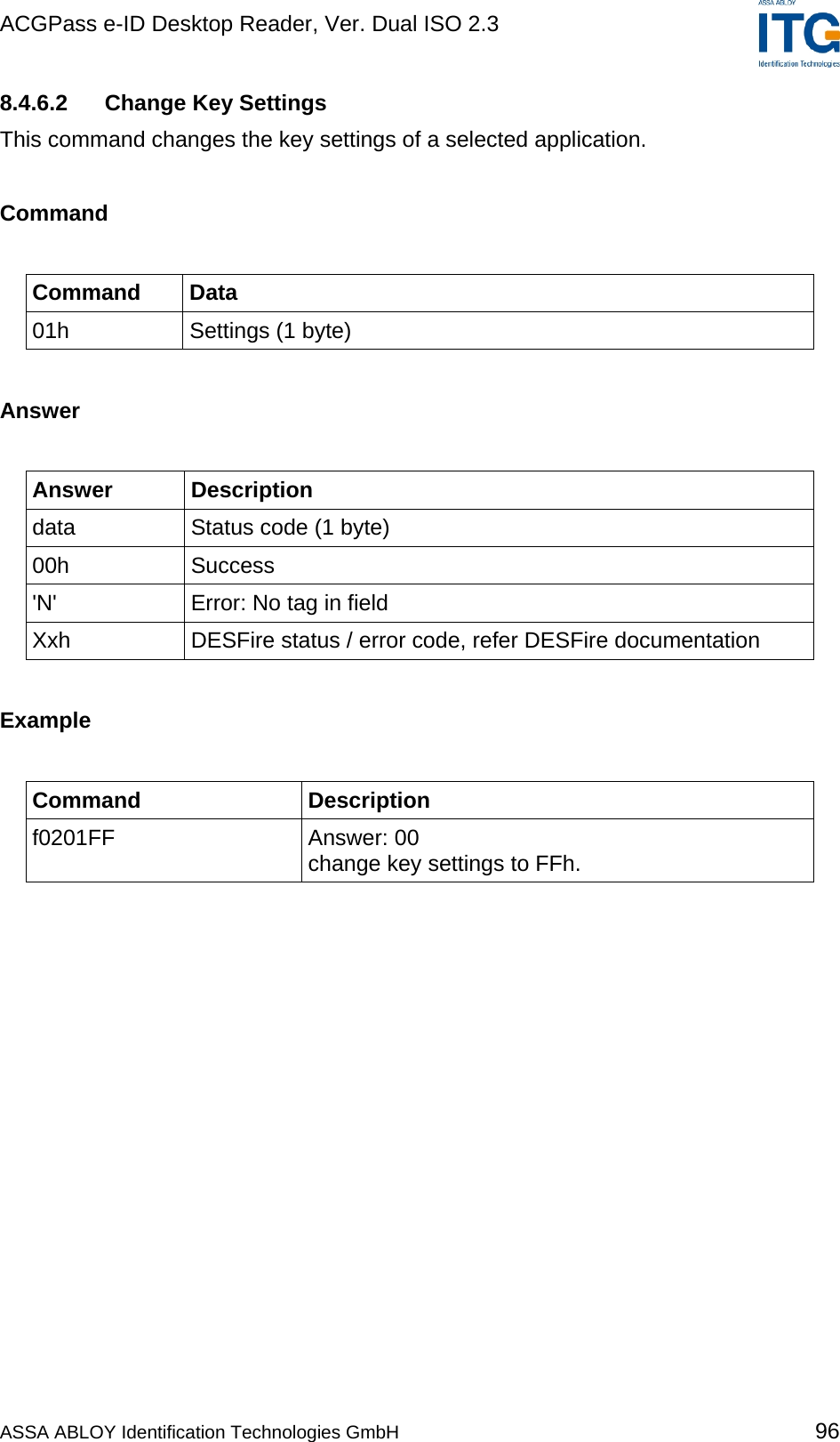
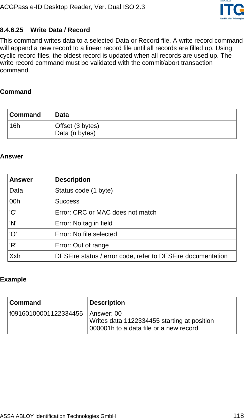
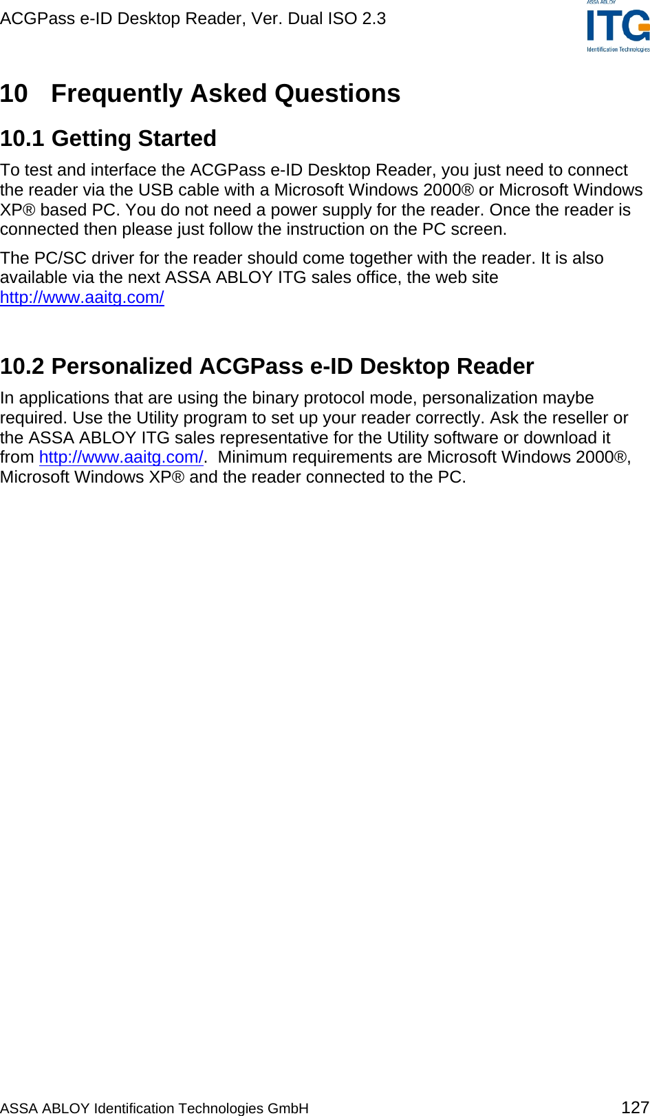
![ACGPass e-ID Desktop Reader, Ver. Dual ISO 2.3 13 Appendix C: Timings tCMD tEXEC tRES PC: Request → Reader: ← Response Command tEXEC [ms] Comments Common commands Cont. read (locked tag) 2.8 – 22.6 + Reset Off and Recovery Time Cont. read (worst case) 54 + 3x Reset Off and Recovery Time DES en/decryption 9.6 – 9.7 TDES en/decryption 28.7 – 28.8 High-speed select 'h08' (locked tag) 8.9 – 14.4 + Reset Off and Recovery Time + SFGT High-speed select 'h08' (no tag) 15 + 3x Reset Off and Recovery Time High-speed select 'h08' (worst case) 14.7 + 3x Reset Off and Recovery Time + SFGT Multiselect (locked tag) 5.8 – 11.4 + Reset Off and Recovery Time Multiselect (no tag) 67 + Reset Off and Recovery Time Multiselect (worst case) 67 + Reset Off and Recovery Time Antenna on 0.2 + Reset Recovery Time Antenna off 0.2 Port read 0.1 Port write 0.1 Read block 1.8 – 2.2 Write block 8.2 – 11 Reset 13.2 Select (locked tag) 5.4 – 22.8 + Reset Off and Recovery Time Select (no tag) 38 + 3x Reset Off and Recovery Time Select (worst case) 55 + 3x Reset Off and Recovery Time ASSA ABLOY Identification Technologies GmbH 136](https://usermanual.wiki/ASSALOY-Identification-Technologies/RDHS-0404D1-0X/User-Guide-795138-Page-137.png)
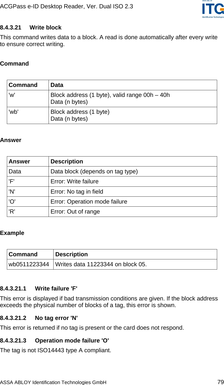
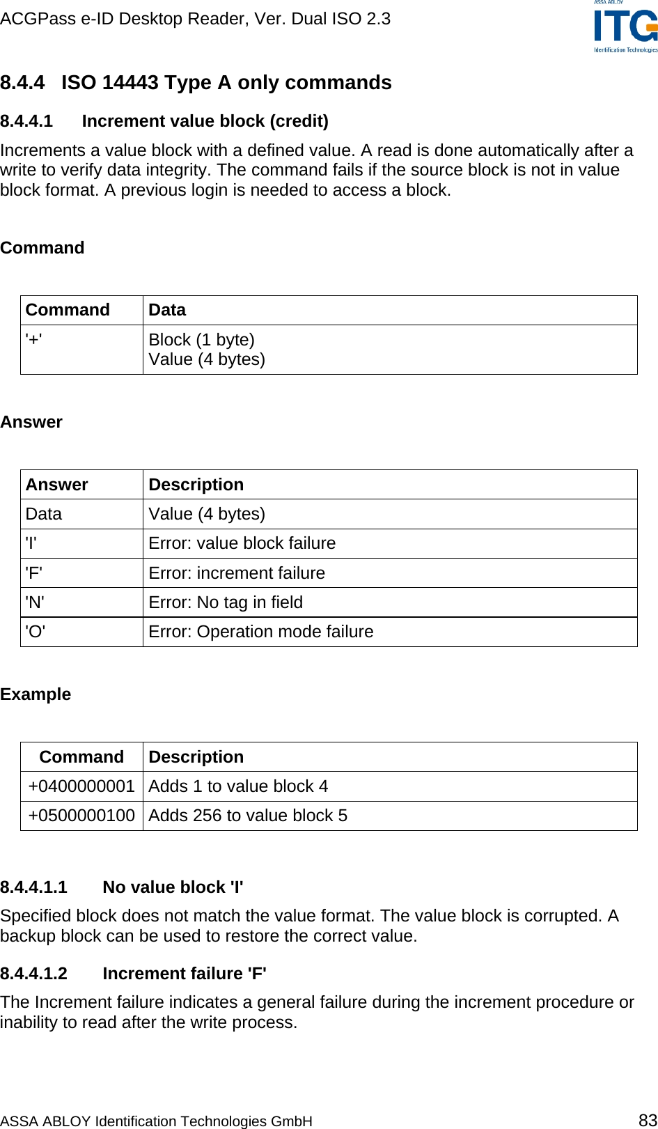
![ACGPass e-ID Desktop Reader, Ver. Dual ISO 2.3 Command tEXEC [ms] Comments ISO 14443 Type A only commands Increment value block 18.4 Decrement value block 18.4 Copy value block 18.5 Read value block 2.3 Write value block 7.9 - 10.5 Mifare Login 4.9 Power conditions Power on 79 Does not include rise time of power supply Enable on 85 Figure 13-1: Timings Default Command Guard Time (20h = 1.2ms) was used. All timing data is advisory application information and does not form part of the specifications. It may change in future firmware releases. Please also note that all values specified in the above table depend on the tag used and Command Guard Time. ASSA ABLOY Identification Technologies GmbH 137](https://usermanual.wiki/ASSALOY-Identification-Technologies/RDHS-0404D1-0X/User-Guide-795138-Page-138.png)