ASSALOY ADA1028W Wireless Interface Module User Manual Stanley Access Technologies
ASSA ABLOY Inc. Wireless Interface Module Stanley Access Technologies
ASSALOY >
Manual
700703
Rev D, 03/20/17
1 of 13
Copyright © 2016, Yale Security Inc., an ASSA ABLOY Group company. All rights reserved.
Reproduction in whole or in part without the express written permission of Yale Security Inc. is prohibited.
700703 Rev D 3/20/17
Installation and
Operating Instructions
ADAEZ Wireless Interface Module (WIM)
Note
Changes or modifications not expressly approved by the party responsible for compliance
could void the user’s authority to operate this device. This device complies with part 15 of
the FCC Rules. Operation is subject to the condition that this device does not cause harmful
interference.
This equipment has been tested and found to comply with the limits for a Class A digital
device, pursuant to part 15 of the FCC Rules. These limits are designed to provide
reasonable protection against harmful interference when the equipment is operated in a
commercial environment. This equipment generates, uses, and can radiate radio frequency
energy and, if not installed and used in accordance with the instruction manual, may cause
harmful interference to radio communications.
This device complies with Industry Canada’s licence-exempt RSSs. Operation is subject to
the following two conditions:
(1) This device may not cause interference; and
(2) This device must accept any interference, including interference that may cause
undesired operation of the device.
Le présent appareil est conforme aux CNR d’Industrie Canada applicables aux appareils
radio exempts de licence. L’exploitation est autorisée aux deux conditions suivantes :
1) l’appareil ne doit pas produire de brouillage;
2) l’appareil doit accepter tout brouillage radioélectrique subi, même si le brouillage est
susceptible d’en compromettre le fonctionnement.
To obtain the latest manual and template revisions or to view installation and programming videos
go to www.nortondoorcontrols.com. For technical support call 800-438-1951 x 4.

700703
Rev D, 03/20/17
2 of 13
Copyright © 2016, Yale Security Inc., an ASSA ABLOY Group company. All rights reserved.
Reproduction in whole or in part without the express written permission of Yale Security Inc. is prohibited.
Installation and Operating Instructions
1. PURPOSE
1.1 Discussion
This manual provides system description, installation instructions, operating instructions, and
troubleshooting recommendations for the ADA EZ Wireless Interface Module (refered to as the
WIM).
The ADA EZ WIM allows the ADA EZ swing door operator to interface with the ADA EZ wired
or wireless pushbuttons, wireless remote, an electric lock, fire panel, access control, and an
outside pushbutton disable contact.
1.2 Applicability
This manual is applicable to the ADA EZ series Wireless Interface Module.
2. PREREQUISITES
2.1 An ADA EZ swing door operator installed according to ADA EZ Pro Installation and Operating
Instructions p/n 700002 with optional Hardwire Kit p/n 1015 or 24VDC (500ma minimum)
power supply by others.
2.2 Plastic electrical enclosure for WIM.
2.3 12 or 24V AC or DC to power the WIM.
2.4 24VDC is REQUIRED if the ADA EZ swing door operator will be powered thorough the WIM
with the supplied cable
2.5 Protective barrier (caution/warning tape) has been set up to prevent unauthorized access to work
area.
2.6 The door has been secured to prevent unexpected opening or closing during installation.
3. PRECAUTIONS
3.1 This product is intended for interior use only.
3.2 An operating door creates pinch hazards. Be careful making operating adjustments while the door
is moving.
3.3 The transformer wiring must not be concealed behind walls or routed through doorways, window
openings, walls, ceilings, or floors. Also, this wiring must be secured to prevent it from becoming
entrapped in the moving parts of the operator or door.
700703
Rev D, 03/20/17
3 of 13
Copyright © 2016, Yale Security Inc., an ASSA ABLOY Group company. All rights reserved.
Reproduction in whole or in part without the express written permission of Yale Security Inc. is prohibited.
4. SYSTEM DESCRIPTION
4.1 General
The ADA EZ WIM allows the ADA EZ swing door operator to interface with:
• ADA EZ wireless (RF) push buttons or
• Wired push buttons
• ADA EZ wireless (RF) hand held transmitter
• Electric Lock
• Access Control
• Fire Panel
• Switch to disable outside pushbutton
4.2 Inputs and Outputs
4.2.1 Pushbuttons: A wired and wireless input is provided for an INSIDE and an OUTSIDE
pushbutton. An optional handheld transmitter p/n HAND-HELD-TX 1031may be
connected to either the INSIDE or OUTSIDE rf pushbutton.
4.2.2 Operator Connection: A connector is provided to plug in the ADA EZ swing door
operator into the WIM module
4.2.3 Access Control: Contacts are provided to interface the WIM with access control.
4.2.4 Lock Interface: Contacts are provided to control an electrical lock.
4.2.5 Lock Power: Contacts are provided to power an electric lock.
4.2.6 Outside Pushbutton Disable: A contact is provided to disable any input from an outside
pushbutton.
4.2.7 Power Input: A power input connector is provided to power the WIM by the optional
hardwire kit p/n KIT-HDWR 1015P.
4.2.8 Signal Delay: A switch is provided to enable a 1 second delay before sending an activate
signal to the door operator
5. INSTALLATION INSTRUCTIONS
5.1 Mount the WIM enclosure in a remote location as desired.
NOTE
The ADA EZ WIM may be powered by 12 or 24 Volts AC or DC current. If the door operator will be
powered directly from the WIM, a 24VDC 750ma (minimum) power supply is required.
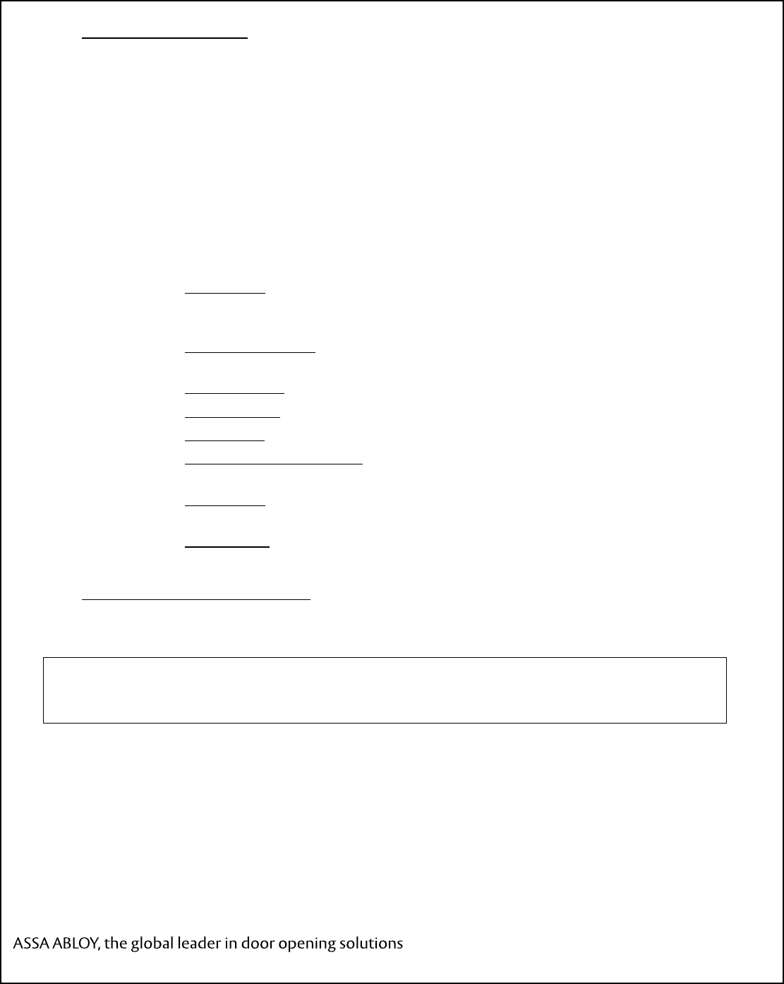
5.2 Provide power to the WIM. (Refer to Figure 1)
5.2.1 If the Optional 1015P hardwire kit is used to power the WIM and door operator, plug the
provided GREEN connector into the power port as shown.
5.2.2 If Power supply is by others, connect the power supply using the provided GREEN
connector. If a DC power supply is used connect the ground to the terminal marked “-“
and the positive to the terminal marked “+”.
5.2.3 If the operator will be powered through the WIM, use the supplied Operator Wire
Harness (p/n 1036) to power the Operator.
700703
Rev D, 03/20/17
4 of 13
Copyright © 2016, Yale Security Inc., an ASSA ABLOY Group company. All rights reserved.
Reproduction in whole or in part without the express written permission of Yale Security Inc. is prohibited.
NOTE
The ADA EZ swing door operator is shipped with wireless RF pushbuttons that are pre-programmed to the
operator. The RF codes MUST be erased from the ADA EZ swing door operator for proper operation.
5.3 Erase All RF codes from the door operator
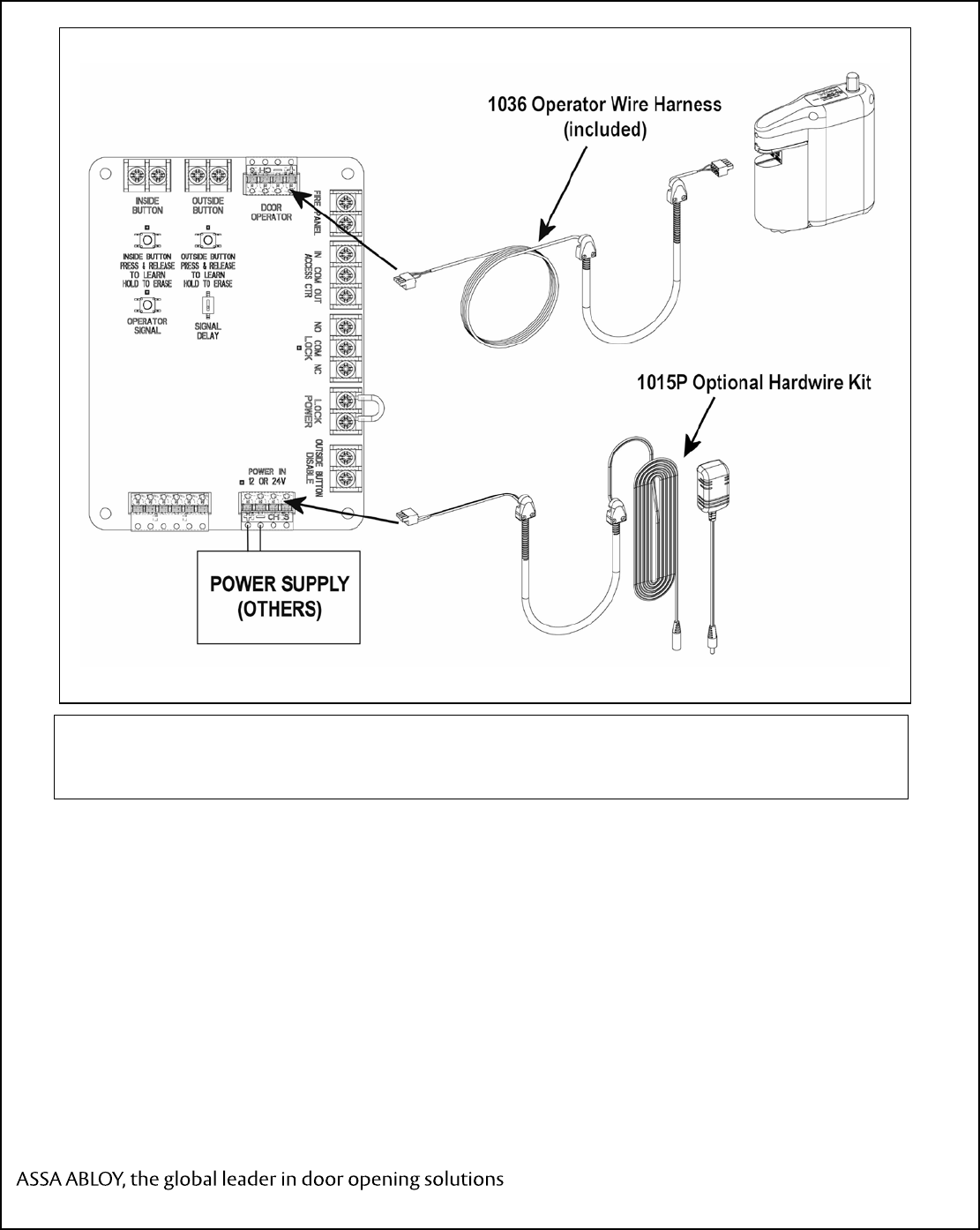
5.3.1 Refer to Figure 2 and Remove the bottom cover from the door operator to access the
Setup board.
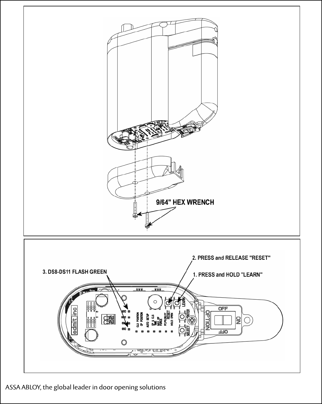
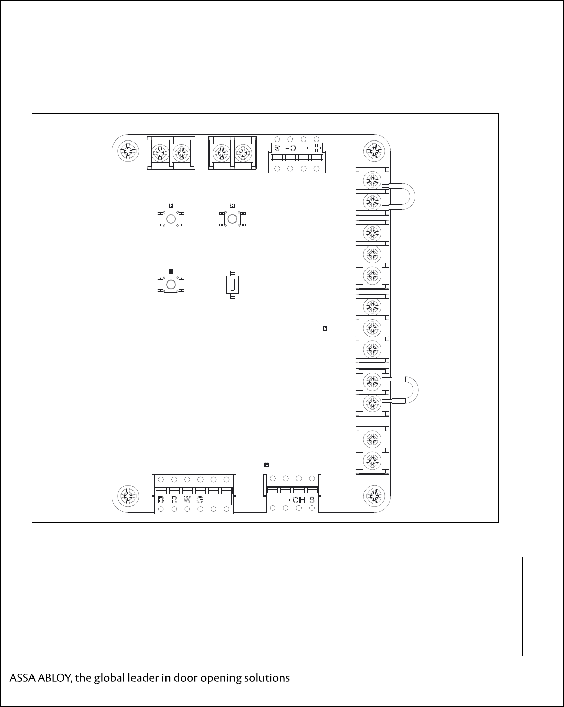
5.3.2 Refer to Figure 3. PRESS and HOLD the LEARN button, PRESS and RELEASE the
RESET button on the setup board.
5.3.3 LEDs DS8 through DS11 shall flash GREEN.
Figure 1. Wiring the WIM and Operator
700703
Rev D, 03/20/17
5 of 13
Copyright © 2016, Yale Security Inc., an ASSA ABLOY Group company. All rights reserved.
Reproduction in whole or in part without the express written permission of Yale Security Inc. is prohibited.
Figure 2. Remove Bottom Cover
Figure 3. Erase learned RF Codes
700703
Rev D, 03/20/17
6 of 13
Copyright © 2016, Yale Security Inc., an ASSA ABLOY Group company. All rights reserved.
Reproduction in whole or in part without the express written permission of Yale Security Inc. is prohibited.
5.1 Learn WIM module to door operator
5.1.1 Refer to Figure 3 and PRESS and HOLD the LEARN button until on the Operator
Control board until LEDs DS8-DS11 Flash Green.
5.1.2 Refer to Figure 4 and PRESS and RELEASE the “OPERATOR SIGNAL” button on the
WIM.
5.1.3 On the Setup board, LEDs DS8 through DS11 shall rapidly flash GREEN 3 times.
5.2 Connect Pushbuttons to WIM
NOTE
The INSIDE pushbutton is considered to be an input from the SECURE side of the door. An INSIDE
activation will switch the LOCK contact, the ACCESS CTR output contact, and send an activation signal
to the door operator.
The OUTSIDE pushbutton is considered to be an input from the NON-SECURE side of the door. An
OUTSIDE activation will switch the LOCK contact, the ACCESS CTR output contact, and send an
activation signal to the door operator ONLY if the ACCESS CTR INPUT contact is CLOSED.
Figure 4. Learn the WIM to the Operator
INSI DE BUTTON
PRESS & RELEASE
TO LEARN
HOLD TO ERASE
OUTSIDE
BUTTON DOOR
OPERATOR
OPERATOR
SIGNAL SIGNAL
DELAY
FIRE PANEL IN COM OUT
ACCESS CTR NO COM NC
LOCK LOCK
POWER OUTSIDE BUTTON
DISABLE
POWER IN
12 OR 24V
OUTSIDE BUTTON
PRESS & RELEASE
TO LEARN
HOLD TO ERASE
INSIDE
BUTTON

700703
Rev D, 03/20/17
7 of 13
Copyright © 2016, Yale Security Inc., an ASSA ABLOY Group company. All rights reserved.
Reproduction in whole or in part without the express written permission of Yale Security Inc. is prohibited.
5.2.1 Refer to Figure 4. If the pushbuttons will be hard wired, connect the INSIDE and
OUTSIDE pushbuttons to the WIM module contacts labeled INSIDE BUTTON and
OUTSIDE BUTTON.
5.2.2 If the INSIDE pusbutton will be connected using RF activation, it must be learned to the
WIM.
a. Refer to Figure 4 and PRESS and RELEASE the “INSIDE BUTTON” button.
b. The Audible will beep and the LED above the button will flash RED if no RF
signals have been learned or GREEN if an RF button is already stored in memory. If
the audible sounds a steady beep and the RED LED lights flashes 4 times rapidly the
RF memory is full and must be reset in order to learn a new RF activation signal.
c. Press and release the INSIDE pushbutton (or optional handheld transmitter or
optional pushbutton) 2 times.
d. The LED will flash and the audible will beep 4 times if the RF signal was
successufully learned.
e. If the pushbutton is not learned the audible will beep for two seconds and exit learn
mode.
5.2.3 If the OUTSIDE pusbutton will be connected using RF activation, it must be learned to
the WIM.
a. Refer to Figure 4 and PRESS and RELEASE the “OUTSIDE BUTTON”
pushbutton.
b. The Audible will beep and the LED above the button will flash RED if no RF
signals have been learned or GREEN if an RF button is already stored in memory. If
the audible sounds a steady beep and the RED LED lights flashes 4 times rapidly the
RF memory is full and must be reset in order to learn a new RF activation signal.
c. Press and release the OUTSIDE pushbutton (or optional handheld transmitter or
optional pushbutton) 2 times.
d. The LED will flash and the audible will beep 4 times if the RF signal was
successufully learned.
e. If the pushbutton is not learned the audible will beep for two seconds and exit learn
mode.
5.3 Erasing RF codes from the WIM
5.3.1 Refer to Figure 4 and PRESS and HOLD the INSIDE BUTTON pushbutton on the WIM
for 5 seconds
5.3.2 The LED will flash RED 4 times and the audible will beep for 4 seconds
700703
Rev D, 03/20/17
8 of 13
Copyright © 2016, Yale Security Inc., an ASSA ABLOY Group company. All rights reserved.
Reproduction in whole or in part without the express written permission of Yale Security Inc. is prohibited.
Figure 5. Connecting an Electric Lock – Series Installation
ELECTRIC
LOCK
LOCK
POWER
SUPPLY
INSIDE BUTTON
PRESS & RELEASE
TO LEARN
HOLD TO ERASE
OUTSIDE
BUTTON DOOR
OPERATOR
OPERATOR
SIGNAL SIGNAL
DELAY
FIRE PANEL IN COM OUT
ACCESS CTR NO COM NC
LOCK LOCK
POWER OUTSIDE BUTTON
DISABLE
POWER IN
12 OR 24V
OUTSI DE BUTTON
PRESS & RELEASE
TO LEARN
HOLD TO ERASE
INSIDE
BUTTON
Figure 6. Connecting an Electric Lock – Parallel Installation
ELECTRIC
LOCK
LOCK
POWER
SUPPLY
INSIDE BUTTON
PRESS & RELEASE
TO LEARN
HOLD TO ERASE
OUTSIDE
BUTTON DOOR
OPERATOR
OPERATOR
SIGNAL SIGNAL
DELAY
F
IRE PANEL
I
N COM OUT
A
CCESS CTR
N
O COM NC
L
OCK
L
OCK
P
OWER
O
UTSIDE BUTTON
D
ISABLE
POWER IN
12 OR 24V
OUTSI DE BUTTON
PRESS & RELEASE
TO LEARN
HOLD TO ERASE
INSIDE
BUTTON

700703
Rev D, 03/20/17
9 of 13
Copyright © 2016, Yale Security Inc., an ASSA ABLOY Group company. All rights reserved.
Reproduction in whole or in part without the express written permission of Yale Security Inc. is prohibited.
5.3.3 Refer to Figure 4 and PRESS and HOLD the OUTSIDE BUTTON pushbutton for 5
seconds
5.3.4 The LED will flash RED 4 times and the audible will beep for 4 seconds
5.3.5 All learned RF codes are now erased.
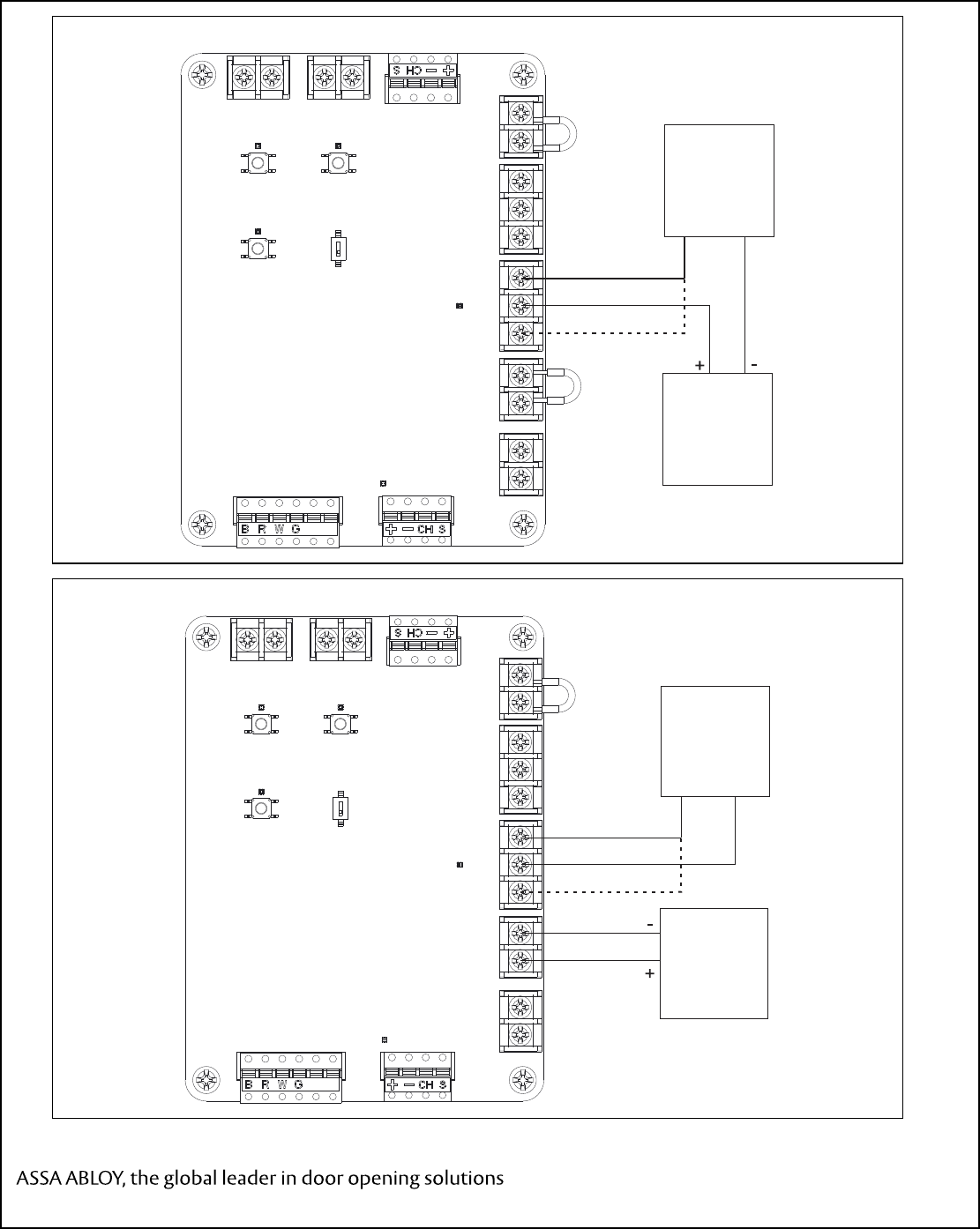
5.4 Connect an Electric Lock to the WIM
NOTE
The electric lock contact will switch state when the INSIDE pushbutton is activated OR the Access
Control input contact is CLOSED.
5.4.1 An electric lock may be connected to the WIM as shown in Series as shown in Figure 5
or in Parallel as shown in Figure 6. If the Parallel installation shown in Figure 6 is used,
the supplied jumper must be removed from the WIM lock power connector.
5.4.2 A normally open or normally closed contact are provided for fail safe or fail secure lock
installation.
5.4.3 An optional signal delay is provided to add a one second time delay between recieiving
an activate signal and sending an activate signal to the door operator. This allows
additional time for the lock to unlock before the door starts to open. If the lock delay is
required, refer to Figure 5 and move the signal delay switch to the top (ON) position.
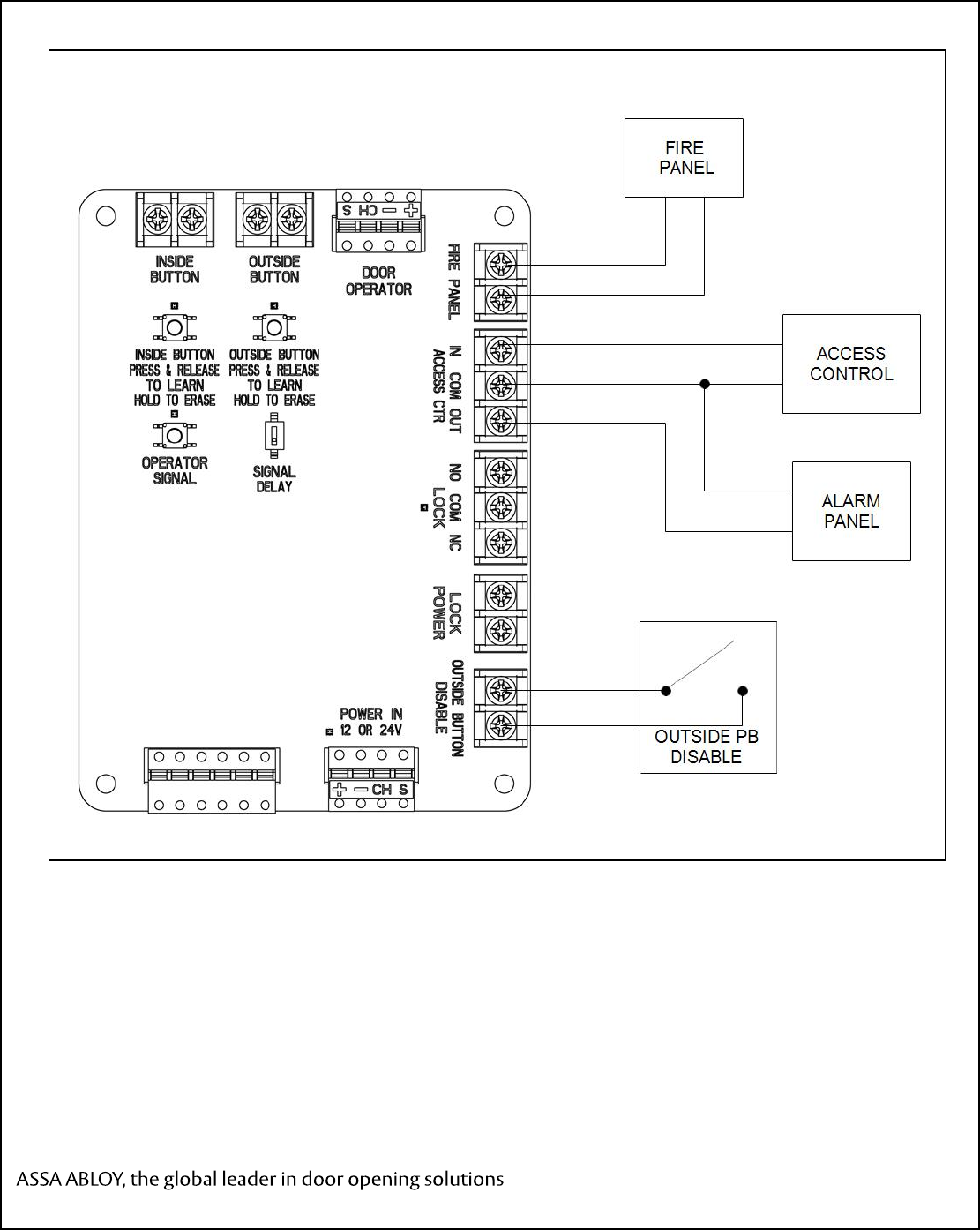
5.1 Connect the WIM to Access Control, Alarm Panel, or Fire Panel.
NOTE
Closing the ACCESS CTRL IN contact will switch the state of the LOCK contact and enable the
OUTSIDE pushbutton.
The ACCESS CTRL OUT contract will close when the WIM module has received an authorized signal to
switch the LOCK contact.
Closing the FIRE PANEL contact will prevent the door operator from accepting an activate signal or will
close the door operator if it is in the open position.
5.1.1 Refer to Figure 7 and connect the optional Access Control Input contact, Alarm Panel
Output contact, or Fire Panel Input contact.
5.2 Connect the OUTSIDE PUSHBUTTON DISABLE
NOTE
Closing the OUTSIDE PUSHBUTTON DISABLE contact will prevent the WIM from accepting an
activation signal from the OUTSIDE pushbutton.
5.2.1 Refer to Figure 7 and Connect the OUTSIDE PUSHBUTTON DISABLE.
700703
Rev D, 03/20/17
10 of 13
Copyright © 2016, Yale Security Inc., an ASSA ABLOY Group company. All rights reserved.
Reproduction in whole or in part without the express written permission of Yale Security Inc. is prohibited.
Figure 7. Optional Interface Connections
700703
Rev D, 03/20/17
11 of 13
Copyright © 2016, Yale Security Inc., an ASSA ABLOY Group company. All rights reserved.
Reproduction in whole or in part without the express written permission of Yale Security Inc. is prohibited.
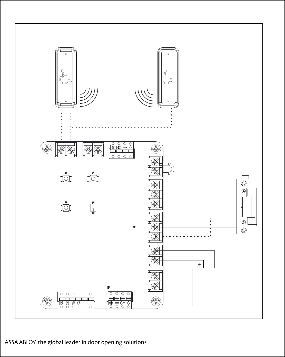
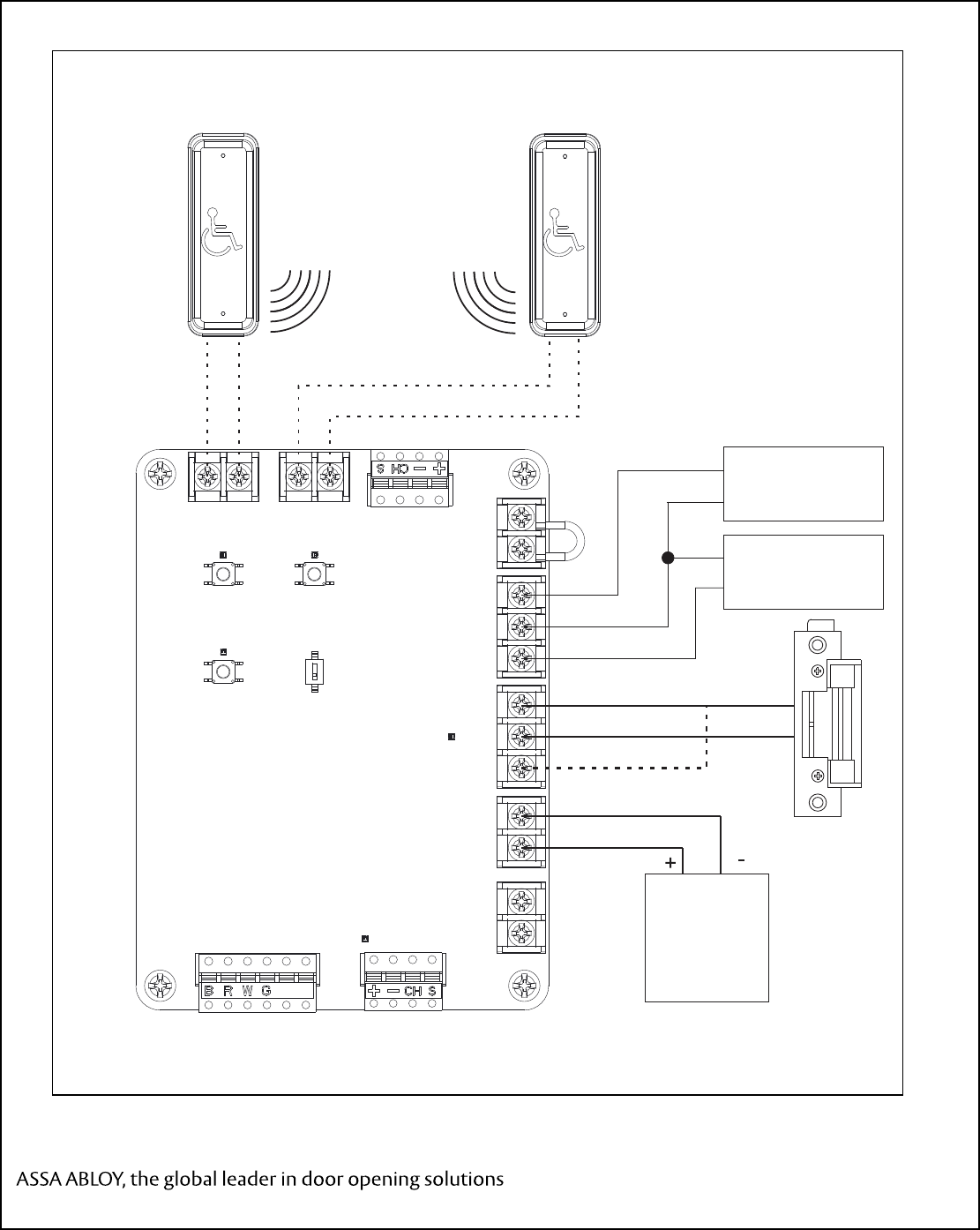
5.3 Wiring diagrams for Common Applications
Figure 8. Electric Strike with RF or Wired pushbuttons – No Access Control
LOCK
POWER
SUPPLY
I NSI DE BUTTON
PRESS & RELEASE
TO LEARN
HOLD TO ERASE
OUTSIDE
BUTTON DOOR
OPERATOR
OPERATOR
SIGNAL SIGNAL
DELAY
FIRE PANEL IN COM OUT
ACCESS CTR NO COM NC
LOCKLOCK
POWER OU
TSIDE BUTTON
DISABLE
POWER IN
12 OR 24V
OUTSI DE BUTTON
PRESS & RELEASE
TO LEARN
HOLD TO ERASE
INSIDE
BUTTON
WIRELESS RF
CONNECTION
OPTIONAL
HARDWIRED
CONNECTION
OPTIONAL
HARDWIRED
CONNECTION
FAIL SECURE
FAIL SAFE
700703
Rev D, 03/20/17
12 of 13
Copyright © 2016, Yale Security Inc., an ASSA ABLOY Group company. All rights reserved.
Reproduction in whole or in part without the express written permission of Yale Security Inc. is prohibited.
Figure 9. Electric Strike with RF or Wired pushbuttons & Card Reader (or other access control)
LOCK
POWER
SUPPLY
I NSI DE BUTTON
PRESS & RELEASE
TO LEARN
HOLD TO ERASE
OUTSIDE
BUTTON DOOR
OPERATOR
OPERATOR
SIGNAL SIGNAL
DELAY
FIRE PANEL IN COM OUT
ACCESS CTR NO COM NC
LOCKLOCK
POWEROU
TSIDE BUTTON
DISA
BLE
POWER IN
12 OR 24V
OUTSI DE BUTTON
PRESS & RELEASE
TO LEARN
HOLD TO ERASE
INSIDE
BUTTON
WIRELESS RF
CONNECTION
OPTIONAL
HARDWIRED
CONNECTION
OPTIONAL
HARDWIRED
CONNECTION
OUTSIDE
BUTTON
INSIDE
BUTTON
FAIL SECURE
FAIL SAFE
CARD
READER
(ACCESS CONTROL)
ALARM
PANEL
700703
Rev D, 03/20/17
13 of 13
Copyright © 2016, Yale Security Inc., an ASSA ABLOY Group company. All rights reserved.
Reproduction in whole or in part without the express written permission of Yale Security Inc. is prohibited.
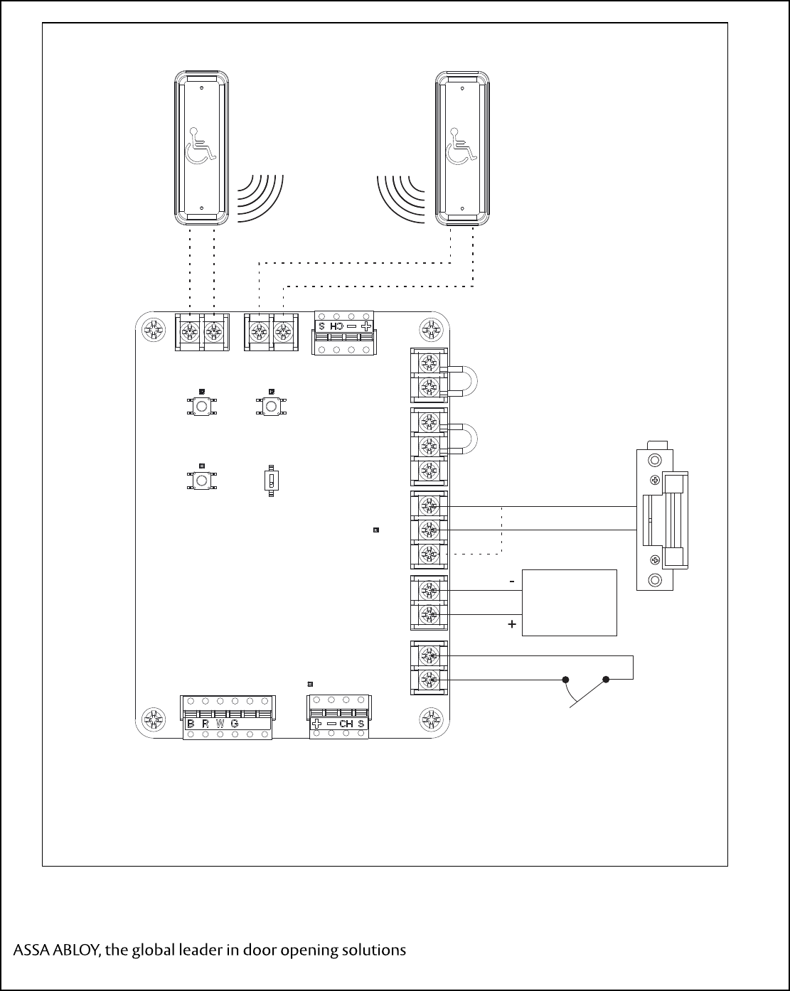
Figure 10. Electric Strike with RF or Wired pushbuttons and Outside Button Disable Switch
LOCK
POWER
SUPPLY
I NSI DE BUTTON
PRESS & RELEASE
TO LEARN
HOLD TO ERASE
OUTSIDE
BUTTON DOOR
OPERATOR
OPERATOR
SIGNAL SIGNAL
DELAY
FIRE PANEL IN COM OUT
ACCESS CTR NO COM NC
LOCK LOCK
POWEROU
TSIDE BUTTON
DISABLE
POWER IN
12 OR 24V
OUTSI DE BUTTON
PRESS & RELEASE
TO LEARN
HOLD TO ERASE
INSIDE
BUTTON
WIRELESS RF
CONNECTION
OPTIONAL
HARDWIRED
CONNECTION
OPTIONAL
HARDWIRED
CONNECTION
OUTSIDE
BUTTON
INSIDE
BUTTON
BUTTON DISABLE
SWITCH
FAIL SECURE
FAIL SAFE