ASSALOY YRHCPZW0 Yale Real Living Electronic Zwave Lock User Manual 12 0002 Exhibit Cover
ASSA ABLOY Inc. Yale Real Living Electronic Zwave Lock 12 0002 Exhibit Cover
ASSALOY >
Contents
- 1. User Manual
- 2. Manual - YRD210-ZW
- 3. Manual - YRD220-ZW
- 4. Manual - YRT210-ZW
- 5. Manual - YRT220-ZW
Manual - YRT220-ZW

5015 B.U. Bowman Drive Buford, GA 30518 USA Voice: 770-831-8048 Fax: 770-831-8598
Certification Exhibit
FCC ID: U4A-YRHZPZW0
IC: 6982A-YRHZPZW0
FCC Rule Part: 15.249
IC Radio Standards Specification: RSS-210
ACS Project Number: 12-0002
Manufacturer: Assa Abloy Inc.
Models: YRD220-ZW, YRD210-ZW, YRT210-ZW, YRT220-ZW
Manual – YRT220-ZW
For Technical Assistance call Yale at 1-800-810-WIRE (9473)
NOTE TO INSTALLER
FAILURE TO FOLLOW THESE INSTRUCTIONS
COULD RESULT IN DAMAGE TO THE PRODUCT
AND VOID THE FACTORY WARRANTY
An ASSA ABLOY Group brand
P/N AYRT-220-INST-FUL Rev A
This document is available on our website in printed Spanish and French. Go to www.yalerealliving.com.
Click "Product Information & Documentation" and then "Installation Instructions".
Este documento está disponible en español en nuestra página de internet. Vaya a www.yalerealliving.com.
Presione "Información del Producto y Documentación" y luego "Instrucciones de Instalación".
Ce document est disponible sur notre site Web dans le français imprimé. Allez à www.yalerealliving.com.
Cliquez sur le "Information sur le produit et Documentation" et puis "Installation Instructions".
Yale Real Living™ Touchscreen Lever
Installation and Programming Instructions
2
An ASSA ABLOY Group brand
P/N AYRT-220-INST-FUL Rev A
Warnings .........................................................................................................................2
Return Lock to Factory Default ................................................................................3
Introduction .....................................................................................................................3
Installation
Components and Tools .............................................................................................4
Prepare Lock for Installation ................................................................................. 5-6
Install Lock .......................................................................................................... 6-11
Programming
Programming Features-Menus-Keys-Definitions ............................................. 12-13
Operation .......................................................................................................... 14-16
Miscellaneous Information
Hardware Troubleshooting .....................................................................................17
Programming Troubleshooting ...............................................................................18
Installing the Network Module ...............................................................................19
Sample Pin Code Management Sheets ........................................................... 23-24
TABLE OF CONTENTS
WARNINGS
FCC:
FCC ID: U4A-YRHCPZW0 (Z-Wave); U4A-YRHCPZB0 (Zigbee)
Model(s): YRT220-ZW, YRT220-ZB
This equipment has been tested and found to comply with the limits for a Class B digital device,
pursuant to Part 15 of the FCC Rules. These limits are designed to provide reasonable protection against
harmful interference in a residential installation. This equipment generates, uses, and can radiate radio
frequency energy and, if not installed and used in accordance with the instructions, may cause harmful
interference to radio communications. However, there is no guarantee that interference will not occur in a
particular installation. If this equipment does cause harmful Interference to radio or television reception,
which can be determined by turning the equipment off and on, the user is encouraged to try to correct
the interference by one or more of the following measures:
• Reorient or relocate the receiving antenna.
• Increase the separation between the equipment and receiver.
• Connect the equipment into an outlet on a circuit different from that to which the receiver
is connected.
• Consult the dealer or an experienced radio/TV technician for help.
IMPORTANT: The accuracy of the door preparation is critical for the proper functioning and
security of this product. Misalignment can cause performance degradation and a lessening of
security.
Finish Care: This lockset is designed to provide the highest standard of product quality and perfor-
mance. Care should be taken to ensure a long-lasting finish. When cleaning is required use a soft, damp
cloth. Using lacquer thinner, caustic soaps, abrasive cleaners or polishes could damage the coat-
ing and result in tarnishing.
Warning: Changes or modifications to this device not expressly approved by Yale Security, Inc.
could void the user's authority to operate the equipment.
3
An ASSA ABLOY Group brand
P/N AYRT-220-INST-FUL Rev A
Factory Default Settings
To reset the lock to factory default, see the following:
The following procedure returns the lock to its factory defaults
by deleting all user codes (including the Master PIN code*) and
returning all programming features to their original default settings
(see below).
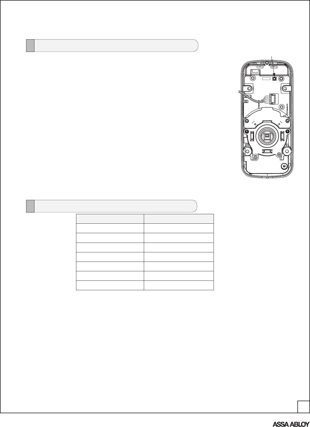
1. Remove the batteries and then remove the inside escutcheon
to access the reset button.
2. The reset button (see image at right) is located above the
PCB cable connector.
3. Hold down the reset button for a minimum of 3 seconds and
then reinstall the batteries; once the batteries are properly
installed, release the reset button.
All features (including adjustable settings** (see below) should
now be returned to factory default.
Upon reset, Master Code Registration is the only option available
and must be performed prior to any other programming of the lock.
See "Operation" later in this manual for programming instructions.
Reset Lock to Factory Default
Reset Button
Inside Escutcheon
Settings Factory Default
Master Code Registration required
Auto Re-lock Enabled
One Touch Re-Lock Enabled
Audio Enabled
Auto Re-lock Time **30 Seconds
Wrong Code Entry Limit **5 Times
Shutdown Time **60 Seconds
**Adjustable only when using Network Module

4
An ASSA ABLOY Group brand
P/N AYRT-220-INST-FUL Rev A
INTRODUCTION
The Yale Real Living™ Stand-alone Touchscreen Deadbolt Lock combines a robust lockset with a
contemporary electronic aesthetic.
Users benefit from an interactive touchscreen that makes day-to-day access effortless, as well as
offering voice-guided programming for simple updates to user information in the event of staffing
changes or security breaches. Yale Real Living™ is engineered for quick and easy installation and
fits in place of a standard deadbolt lock door prep (ANSI/BHMA A156.115).
If this is an RF-enabled network lock, it needs to be located within 50 - 100 feet of another network
controller. That distance is influenced by objects between the lock and the controller and may be
expanded depending on proximity to other RF network devices. Also, if the lock is connected to a
network controller, it is recommended that it is programmed through the centralized user interface
(PC or hand-held device) to ensure communication between the lock and the controller unit.
Industry Canada:
Canadian ID: 6982A-YRHCPZW0 (Z-Wave); 6982A-YRHCPZB0 (Zigbee)
Model(s): YRT220-ZW, YRT220-ZB
This Class B digital apparatus meets all requirements of the Canadian Interference Causing Equipment
Regulations. Operation is subject to the following two conditions: (1) this device may not cause harmful
interference, and (2) this device must accept any interference received, including interference that may
cause undesired operation.
Cet appareillage numérique de la classe B répond à toutes les exigences de l’interférence canadienne
causant des règlements d’équipement. L’opération est sujette aux deux conditions suivantes: (1) ce
dispositif peut ne pas causer l’interférence nocive, et (2) ce dispositif doit accepter n’importe quelle
interférence reçue, y compris l’interférence qui peut causer l’opération peu désirée.
For the U4A-YRHCPZB0 and 6982A-YRHCPZB0, the following statement applies:
“This equipment complies with FCC/IC radiation exposure limits set forth for an uncontrolled
environment. This equipment should be installed and operated with minimum distance 20cm between
the radiator and your body. This transmitter must not be co-located or operating in conjunction with any
other antenna or transmitter.”
Section 7.1.2 of RSS-GEN Under Industry Canada regulations, this radio transmitter may only operate
using an antenna of a type and maximum (or lesser) gain approved for the transmitter by Industry
Canada. To reduce potential radio interference to other users, the antenna type and its gain should be
so chosen that the equivalent isotropically radiated power (e.i.r.p.) is not more than that necessary for
successful communication.
En vertu des règlements d'Industrie Canada, cet émetteur radio ne peut fonctionner avec une antenne
d'un type et un maximum (ou moins) approuvés pour gagner de l'émetteur par Industrie Canada. Pour
réduire le risque d'interférence aux autres utilisateurs, le type d'antenne et son gain doivent être choisies
de façon que la puissance isotrope rayonnée équivalente (PIRE) ne dépasse pas ce qui est nécessaire
pour une communication réussie.
Section 7.1.3 of RSS-GEN This Device complies with Industry Canada License-exempt RSS standard(s).
Operation is subject to the following two conditions: 1) this device may not cause interference, and 2)
this device must accept any interference, including interference that may cause undesired operation of
the device.
Cet appareil est conforme avec Industrie Canada RSS standard exemptes de licence(s). Son
fonctionnement est soumis aux deux conditions suivantes: 1) ce dispositif ne peut causer des
interférences, et 2) cet appareil doit accepter toute interférence, y compris les interférences qui peuvent
causer un mauvais fonctionnement du dispositif.
5
An ASSA ABLOY Group brand
P/N AYRT-220-INST-FUL Rev A
Lock Installation
#2 Phillips screw driver
Allen wrench (3mm) - provided
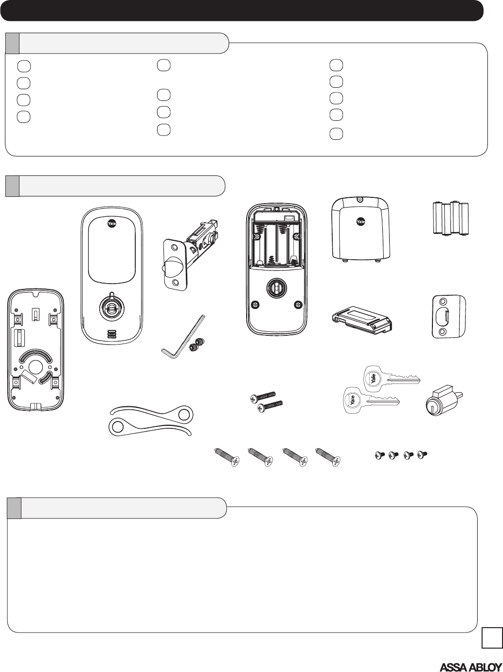
Parts Illustrations
Tools Needed
COMPONENTS AND TOOLS
INSTALLATION
4 AA Alkaline
Batteries
Latch bolt
Strike
Door Prep
2-1/8" (54mm) hole saw
1" (26mm) boring bit
7/64" (2.5mm) drill bit
Chisel & hammer
Battery Cover
Network Module
(Optional)
Outside
Escutcheon
Latch
Keys
(4) Inside Escutcheon
Mounting Screws
(Pack 1)
(2) Inside Mounting Plate Screws
(Pack 1)
(2) Latch & (2) Strike Plate Mounting
Screws (Pack 2)
Cylinder
Installation Instructions
Template
Latch Bolt
Strike Plate
Included in the box. . .
Inside Mounting Plate
(with gasket)
Inside Escutcheon
Outside Escutcheon
(2) Screw Packs (see below)
Keys
Cylinder
Battery Cover
Allen Wrench
4 AA Alkaline Batteries
Allen Wrench
(2) Hex Set Screws
(Pack 1)
Inside
Escutcheon
Outside & Inside Lever
Handles
Inside Mounting Plate
with Gasket
(back of Inside Escutcheon)
6
An ASSA ABLOY Group brand
P/N AYRT-220-INST-FUL Rev A
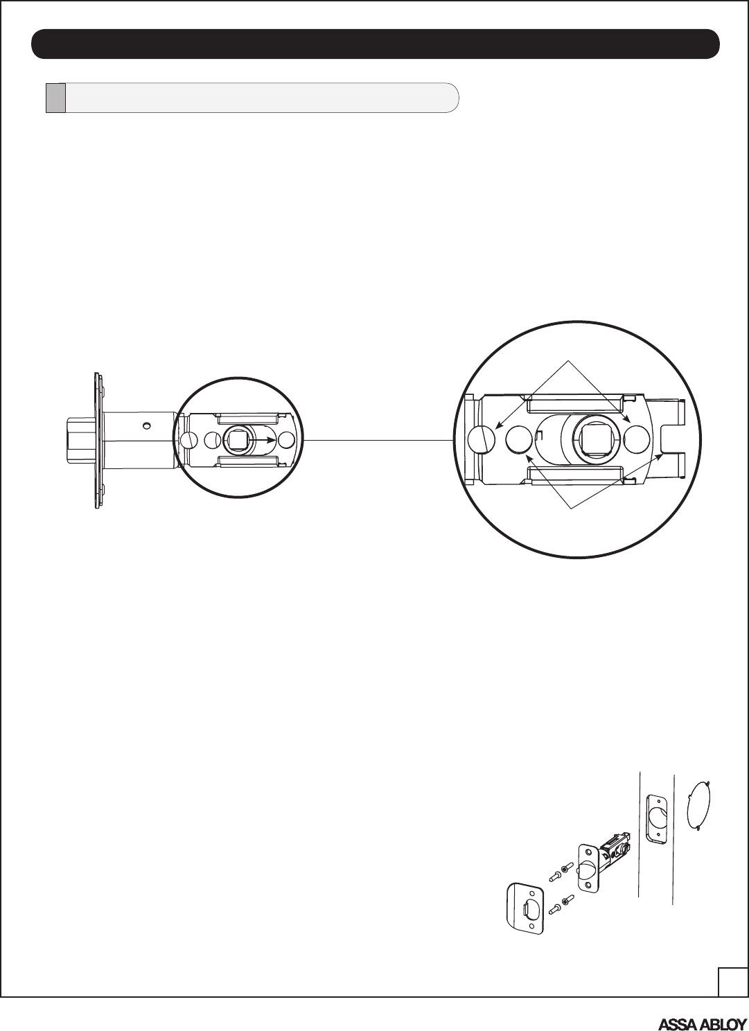
INSTALL LOCK
Install Latch
A. Remove the latch (Fig. 1) and strike plate from the packaging.
NOTE: Latch ships with backset in 2-3/8" position (Fig. 1).
Backset is the measurement from door edge to center
of 2-1/8" diameter hole (see template supplied with lock).
If required, pull to extend to 2-3/4" backset position (Detail 1A).
NOTE: Different holes are used for (2) through bolts depending on backset (see Detail 1A).
Figure 1
Detail 1A
2-3/8" through bolt posts
2-3/4" through bolt posts
The lock is packed representative of how it will install on the door.
Before installing the lock on the door:
B. Install latch bolt in door.
1. Attach with two (2) M4 x 25.4mm screws supplied.
C. Install strike on the door frame, using two (2) M4 x 25mm
screws supplied, making sure to allow for the latch to be
centered in the strike.
NOTE: The latch bolt (and strike) can be installed in only one of two ways -
with the bevel (slope) of latch facing out or facing in while standing
outside of the door.
If the door opens in, the bevel will face the outside; if the doors opens out, the
bevel will face in.
The strike plate is installed according to the orientation of the latch bolt. See
Figures 1 & 2 for an example of a RH door that opens in.
NOTE: Make sure door has been prepped according to specifications in template included
with lock.
(4) M4 x 25.4mm
Flat Head
Combination Screws
NOTE: Both latch face and strike plate have adhesive-backed covers to
prevent marring and should be removed upon installation.
Figure 2
7
An ASSA ABLOY Group brand
P/N AYRT-220-INST-FUL Rev A
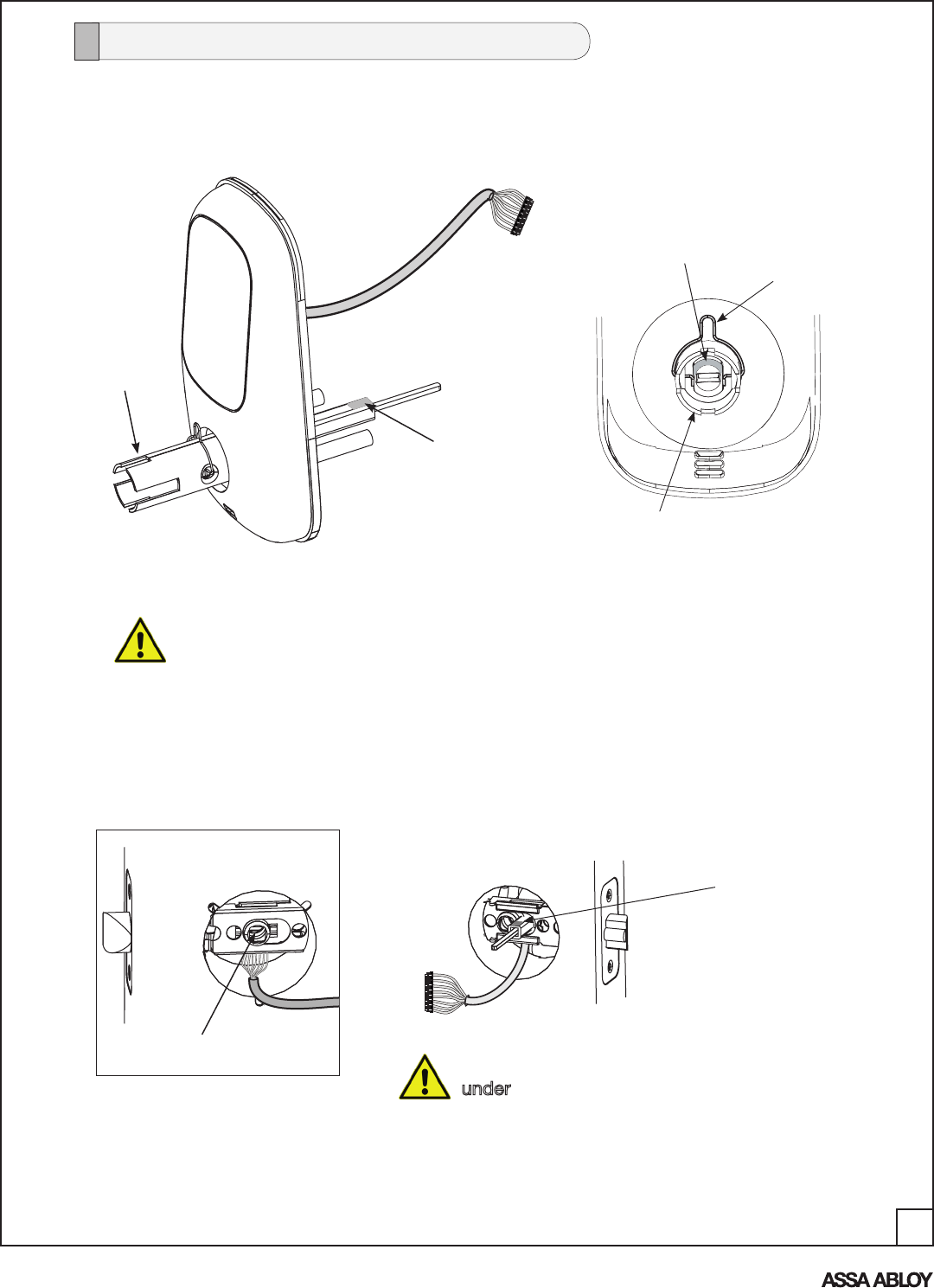
Figure 1A
Outside Escutcheon
(with gasket)
Do not remove clip from Outside Escutcheon shank until correct handing has
been determined and Outside Lever Handle is to be installed.
(See page 9)
Clip
Shank
NOTE: RED marking
indicates "top" of hub
1. From outside of door, position the outside escutcheon by first routing the cable
through 2-1/8" diameter hole and under the latch (Fig. 3A & B), then insert
posts* and tailpiece into the latch.
Square
Drive Tube
is marked
(WHITE) to
indicate
"top"
NOTE: The "tops" of both the square drive tube and the hub (in the shank) are marked to
indicate their orientation for proper installation (Figures A & B).
Shank
NOTE: Cable goes
under latch (Fig. 1A & 1B).
Outside of Door
Figure 1B
Inside of Door "Top" of Drive Tube
(marked WHITE)
Tailpiece
*Posts are inserted in holes according to
backset adjustment. (Refer back to Detail 1A
under "Install Lock")
Install Outside Escutcheon
Figure A Figure B
8
An ASSA ABLOY Group brand
P/N AYRT-220-INST-FUL Rev A
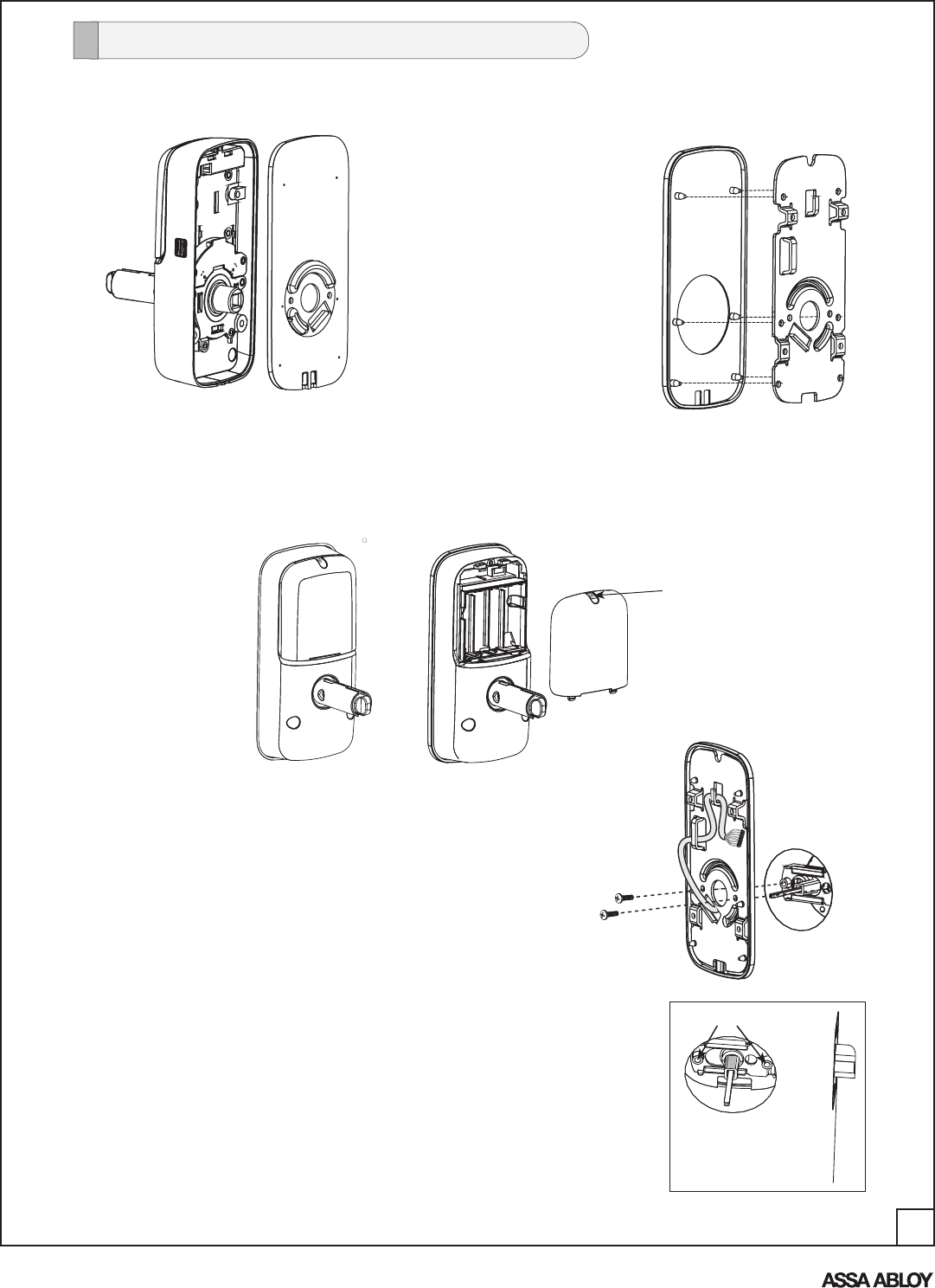
2. Remove the inside mounting plate (with gasket) from
the back (door side) of the inside escutcheon (Fig. 2A).
A. Ensure that gasket on
inside mounting plate
is properly fitted (Fig. 2B).
Figure 2B
Figure 2A
Inside Escutcheon & Mounting Plate
(with gasket)
3. Remove the battery cover from the back of the inside escutcheon (Fig. 3) by loosening
the captive Phillips head screw.
Inside of Door
5. Secure both assemblies by inserting (2) M4 x 25mm
pan head machine screws through the mounting
plate and into the slightly extended through posts of
the outside escutcheon (Fig. 4B).
Ensure that outside escutcheon is vertically aligned.
Tighten securely with a #2 Phillips screwdriver.
Do not over-tighten.
4. Holding the outside escutcheon flush to the door,
position the inside mounting plate by routing the
cable/connector through the mounting plate's 1/2"
rectangular hole below center hole (Fig. 4A).
Figure 4A
6. Finish routing the cable and connector through the left
upper slot, then behind center rib as shown in Fig. 4A.
Figure 4B
Through posts here
Screw
Battery Cover
Install Outside Escutcheon
Figure 3
9
An ASSA ABLOY Group brand
P/N AYRT-220-INST-FUL Rev A
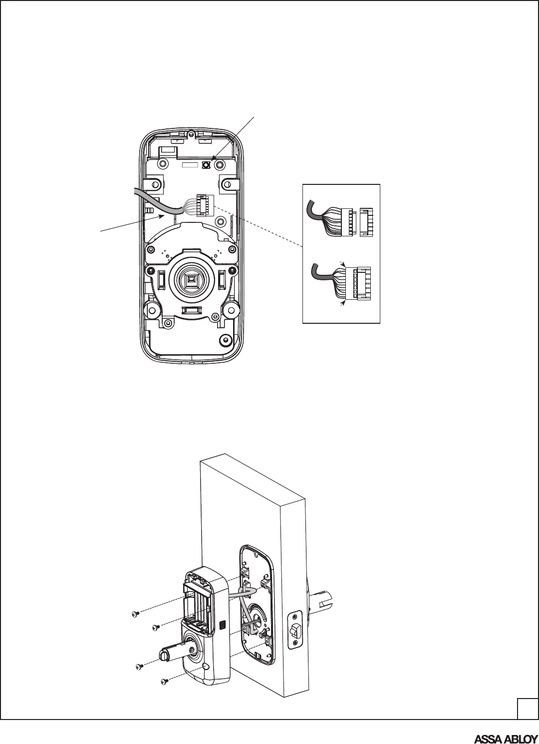
7. Attach cable assembly to the inside escutcheon printed circuit board (PCB) by lining up
notches on top of cable connector to slots on PCB connector (Fig. 7A & 7B).
Press connector in firmly using thumbs until completely seated (properly seated position
indicated by arrows on PCB as in Fig. 7B).
8. Install and secure inside escutcheon to inside mounting plate using (4) M4 x 8mm
[8-32 x 5/16"] pan head machine screws through the inside escutcheon into the
mounting plate (Fig. 8).
NOTE: Make sure cable does not obstruct path of the mounting screws.
Inside Escutcheon
Reset Button
Figure 7B
Figure 7A
Cable Connector
Figure 8
10
An ASSA ABLOY Group brand
P/N AYRT-220-INST-FUL Rev A
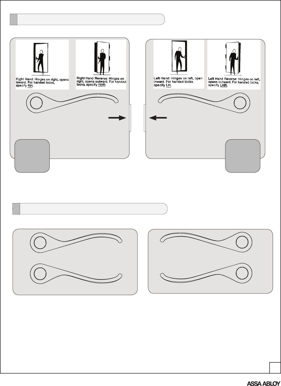
Determine Lever Handing
Hinges on Right Hinges on Left
RH
RHR
Lever
LH
LHR
Lever
Right handed
lever position
Left handed
lever position
Before proceeding with the next step, ensure correct lever handing for proper installation.
Correct "curved" position Correct "curved" position
Incorrect Incorrect
Determine Lever Position
Both outside and inside lever handles should
always point toward the door hinges.
11
An ASSA ABLOY Group brand
P/N AYRT-220-INST-FUL Rev A
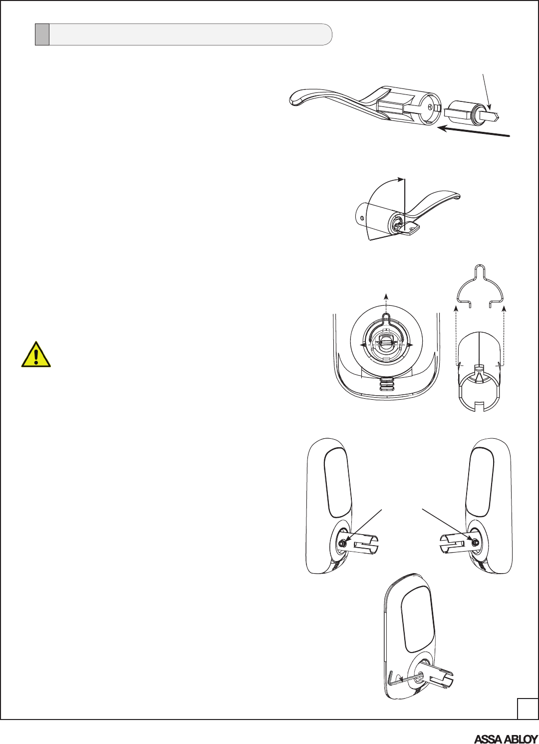
Hex Screw
RH/RHR LH/LHR
NOTE: For correct lever handing, the
hex set screw for the outside
lever shank must be installed
as shown (Fig. 8B).
Figure 8B
Figure 1C
A. Once correct handing is determined, remove the
clip that has held the hub in its correct position by
spreading clip ends to extract clip from shank as
shown in Figure 1C with detail.
Do not rotate cam from its original position.
("top" is marked RED)
2. Remove clip from shank.
3. Install hex set screw.
Install the Exterior Lever (Right Hand shown)
1. Install cylinder in exterior lever.
(If necessary, remove key from cylinder)
A. Drop cylinder in exterior lever handle as shown.
90°
B. Insert key in cylinder.
A. Place set screw in hole on side of
shank toward edge of door (opposite
lever handle); turn CW to allow placement
of lever handle over shank.
Do not overtighten.
CW
Figure 1A
Figure 1B
Tailpiece
While supporting cylinder tailpiece (with finger);
rotate key 90° clockwise (CW) to vertical position
(Figure 1B).
NOTE: RH shown; with LH lever, rotate key 90°
counter-clockwise (CCW)
12
An ASSA ABLOY Group brand
P/N AYRT-220-INST-FUL Rev A
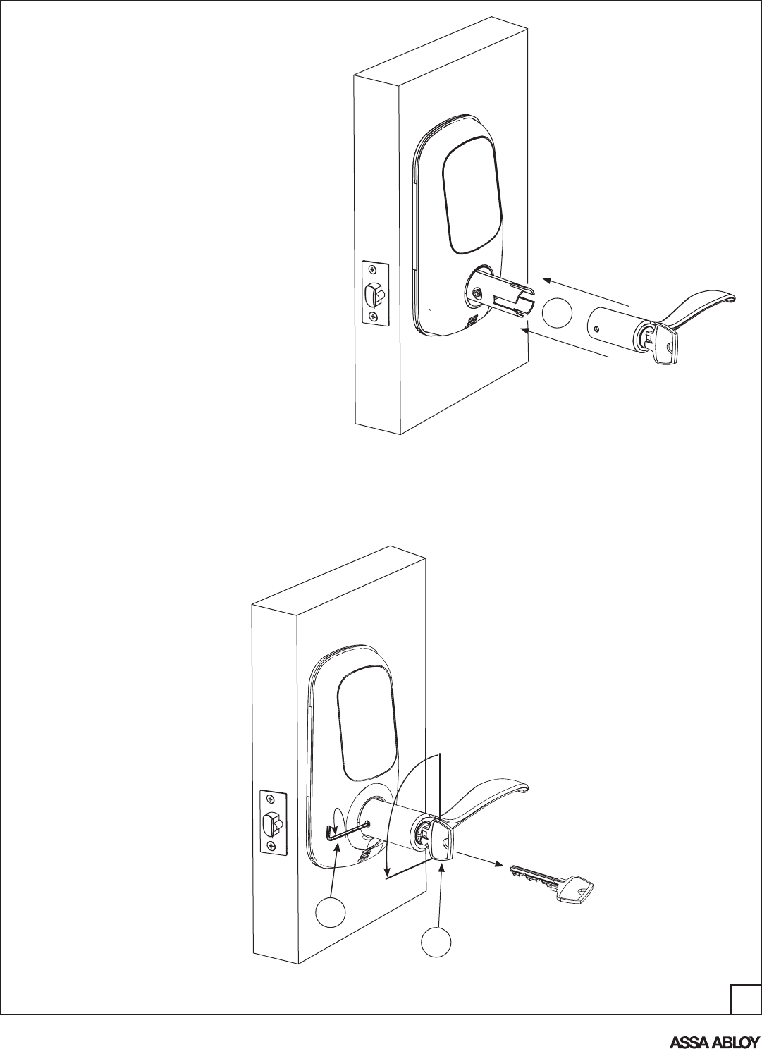
E
Figure 1E
F. Secure lever handle by inserting allen wrench and rotating set screw CCW (Fig. 1F).
Do not overtighten.
G. Turn key 90° CCW; pull to remove key and test operation of lever handle, ensuring
that the latch moves smoothly.
G
90°
F
Figure 1F
CCW
E. Push lever handle (with key & cylinder)
over shank until hole on handle aligns
with set screw in shank (Figure 1E).
13
An ASSA ABLOY Group brand
P/N AYRT-220-INST-FUL Rev A
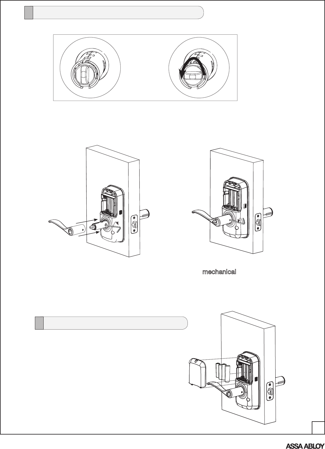
3. Turn set screw CCW to tighten
and secure lever handle to shank.
1. Insert four (4) AA alkaline batteries; the lock
will flash and beep several times.
2. Install battery cover and tighten Phillips
head screw.
IMPORTANT: Before installing the batteries, test the mechanical operation of lock
by rotating both the outside and inside lever handles. Also try using both the thumbturn
and key. The movement of the latch should be smooth and unobstructed.
If operation is not smooth, review the previous steps to ensure proper installation, while
maintaining proper alignment of escutcheons.
1. Rotate thumbturn counter-clockwise to horizontal position (Fig. 9A).
2. Insert set screw on side of shank (toward
edge of door); turn CW to allow placement
of inside lever handle over shank.
Figure 9A
Figure 9B Figure 9C
Install the Exterior Lever (Right Hand shown)
Install Batteries
14
An ASSA ABLOY Group brand
P/N AYRT-220-INST-FUL Rev A
PROGRAMMING
PROGRAMMING FEATURES - MENUS - KEYS - DEFINITIONS
Programming Features-Menus-Keys-Definitions ............................................. 12-13
Operation .......................................................................................................... 14-17
Phillips Screw
Network Module Slot
Alkaline Batteries
4 AA Type
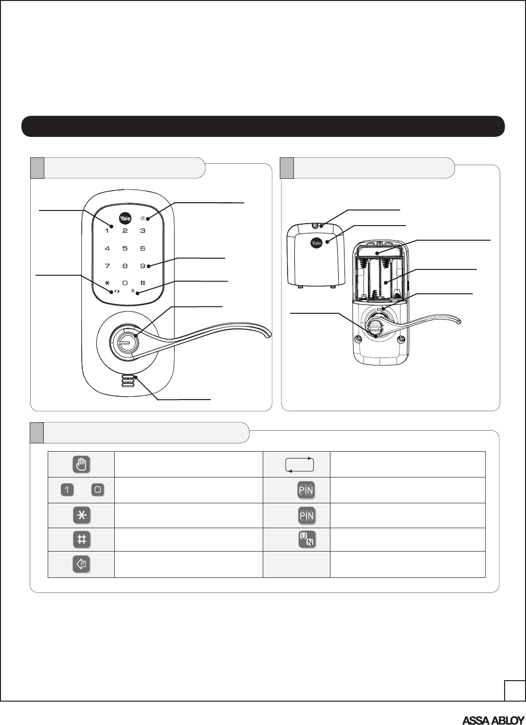
Inside Handle
Status Indicator
Battery Cover
Outside Inside
Speaker Hole
Lockout Mode
Cylinder
Low Battery
Indicator
Numbers
Touch Screen " P " Key
(Return to Previous)
Menu and Icons
Touch the screen with palm of hand or
fingers to begin and end actions. Repeat operation using settings indicated.
Enter Value 1 -10 (times or seconds).
Click the indicated number. Enter Master PIN code* (4-8 digits in length).
Advanced Mode only.
Press the Star key on the touchscreen to
Enter or Accept entry. Enter User PIN. Can be 4-8 digits in length.
Press the Pound key on the touchscreen to
enter Menu mode.
User Serial Number (01 - 25);
RF Controlled (01-250).
Press this key to return to the previous
step or menu setting.
M
U
~
*The Master Pin Code must be registered prior to any further programming of the lock.
15
An ASSA ABLOY Group brand
P/N AYRT-220-INST-FUL Rev A
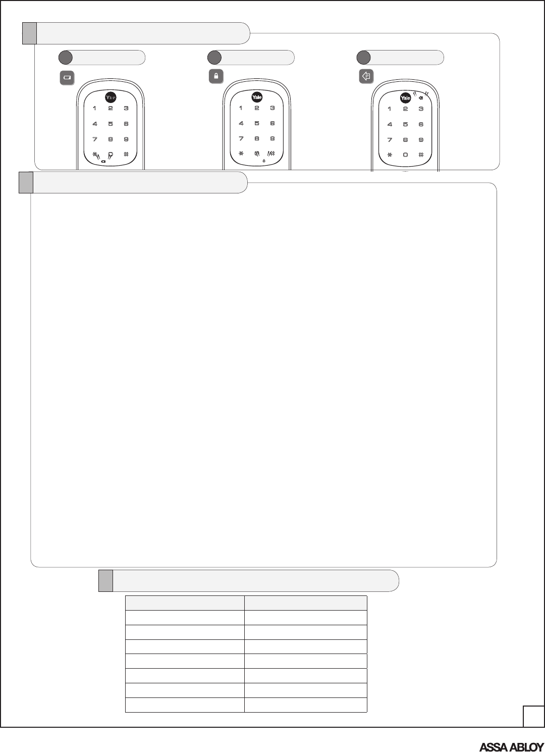
Low Battery Warning
1 Lockout Mode
2 Return to previous step
3
Status Indicators
Lockout Mode: This feature is enabled by the Master code. When enabled, it restricts all user PIN
code access. When attempting to enter a code while the unit is in Lockout, the Status Indicator
flashes RED and BLUE; the keypad flashes as well.
Low Battery: When battery power is low, the Status Indicator flashes RED. If battery power is
completely lost, use the key override.
Master PIN Code: The Master code is used for programming and for feature settings. NOTE: The
Master Pin Code must be registered prior to programming the lock. The Master code will also
operate the lock.
Auto Re-lock Time: After successful code entry and the unit unlocks, it will automatically re-lock
after a default of thirty (30) seconds. Re-lock time is adjustable from five (5) to thirty (30) seconds.
One Touch Re-Lock: When the bolt is retracted, activating the keypad will extend the bolt
(during Auto Re-Lock duration or when Auto Re-Lock is disabled).
Shutdown Time: The unit will shutdown for a default of sixty (60) seconds and not allow operation
after the wrong code entry limit has been met. When the unit is in Shutdown, the Status Indicator
flashes RED and BLUE; the keypad flashes as well.
Audio Mode: Choosing Disable (3) in Audio mode shuts off the code confirmation tone playback
for use in quiet areas. Audio mode is enabled or disabled through feature programming by the
Master code.
Status LED: Located on inside escutcheon.
User PIN Code: The User code operates the lock. Maximum number of user codes is 250 with
Network Module; without Network Module, maximum is 25 user codes.
Wrong Code Entry Limit: After a specified number of unsuccessful attempts at entering a valid
PIN code the unit will shut down and not allow operation. Wrong code entry limit is adjustable from
three (3) to ten (10) times through feature settings (up to 5 times with no RF network enabled - de-
fault is 5; 10 with RF network enabled).
Definitions
Factory Default Settings
*Adjustable with Network Module
Settings Factory Default
Master Code Registration required
Auto Re-lock Enabled
One Touch Re-Lock Enabled
Audio Enabled
Auto Re-lock Time **30 Seconds
Wrong Code Entry Limit **5 Times
Shutdown Time **60 Seconds
16
An ASSA ABLOY Group brand
P/N AYRT-220-INST-FUL Rev A
OPERATION
1
Press the key. Enter the new Master PIN code (4~8
digits), followed by the key.
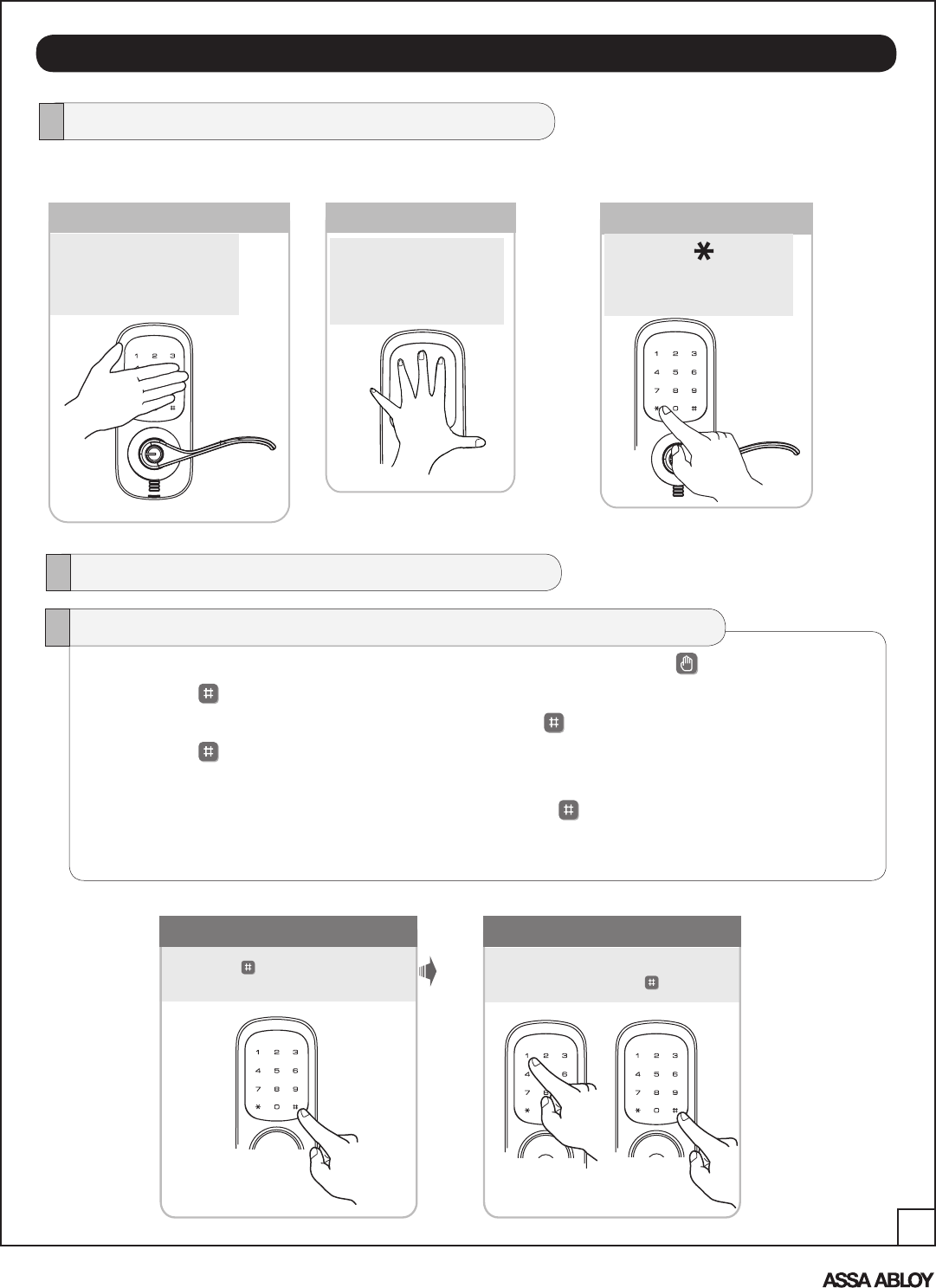
Lock Activation
The touchscreen can be activated in several ways:
Lock Operation
Touch lock with
back of hand or
fingers to activate.
Press the key to
activate.
Touch lock with
fingers spread to
activate.
1. Touch the screen with the back of your hand or fingers to activate .
2. Press the key.
Lock Response: “Register Master Code; press the key to continue.”
3. Press the key.
Lock Response: “Enter a 4 to 8 digit pin code followed by the pound key."
4. Enter new 4-8 digit Master PIN code followed by the key.
Lock visually confirms pin code selection, announces "Handing lock", the motor engages
and the lock responds, "Completed".
Master Code Set*
*This step is required prior to programming of the lock.
17
An ASSA ABLOY Group brand
P/N AYRT-220-INST-FUL Rev A
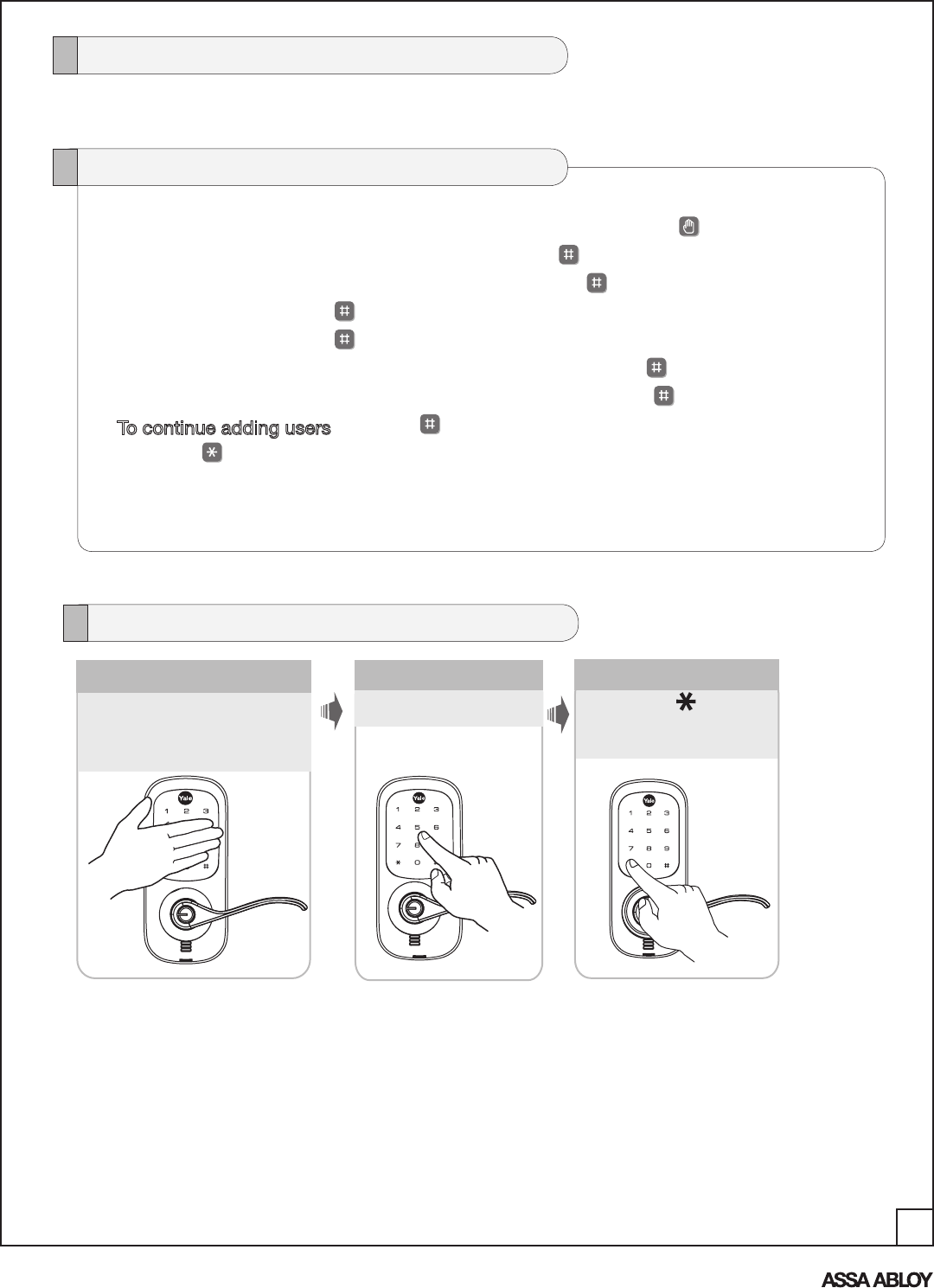
User PIN Codes can only be programmed through the Master PIN Code*.
1. Touch the screen with the back of your hand or fingers to activate .
2. Enter the 4-8 digit Master PIN code followed by the key.
Lock Response: “Menu mode, enter number, press the key to continue.”
3. Enter “2” followed by the key.
4. Enter “1” followed by the key.
5. Enter the User Number to be registered (1-25) followed by the key.
6. Enter a 4-8 digit PIN code for the User number followed by the key.
7. To continue adding users press the key.
8. Press the key to complete the process and conclude the programming session.
Set Up User PIN Codes
Note: When registering User codes, the code must be entered within 20 seconds or
time expires, Lock Response: “Time expired”, no codes are registered and the process
must be re-started.
3
Press the key
to confirm the
selection.
Enter PIN code.
2 1
Touch lock with
back of hand or
fingers to activate.
PIN code structure
Maximum number of user codes is 250 with Network Module; without Network Module,
maximum is 25 user codes.
Open Door with PIN Code
*Master PIN code must be registered before User codes can be added.
18
An ASSA ABLOY Group brand
P/N AYRT-220-INST-FUL Rev A
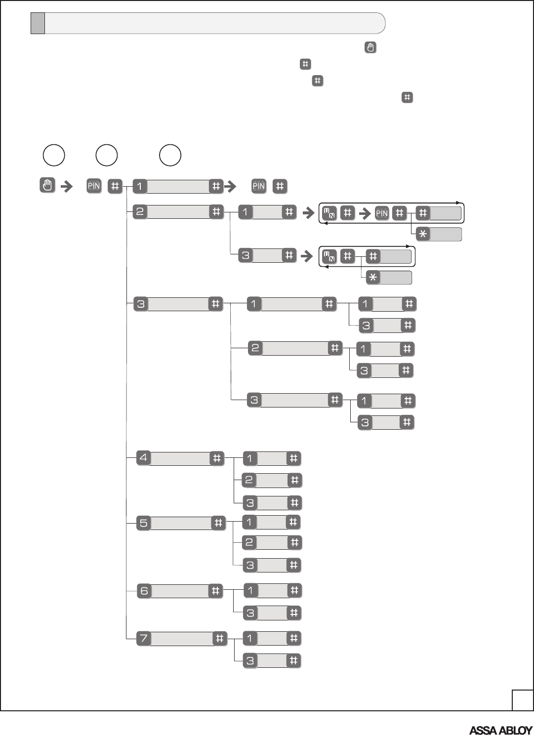
Master PIN Code Setting
MM
User PIN Code Registration
Register
Delete
Advanced Lock Settings
Volume Setting
Language Setting mode
Lockout Mode
**Network Module Setting Register
High
English
Enable
Disable
Delete
Silent
Spanish
French
Low
User Number (UN)
1~25: without network module
1~250: with network module
1 2 3
UContinue
Complete
Continue
Complete
**This function appears
only with RF network
module installed.
Auto Re-lock Setting Enable
Disable
Inside Escutcheon LED
One Touch Locking Setting Enable
Disable
Feature Programming Through Menu Mode Using Master PIN code*
1. Touch the screen with the back of your hand or fingers to activate .
2. Enter the 4-8 digit Master PIN code* followed by the key.
Lock Response: “Menu mode, enter number, press the key to continue.”
3. Enter digit corresponding to the function to be performed followed by the key.
Follow the voice commands.
Note: If the lock is connected to a network controller, it is
recommended that it is programmed through the central-
ized user interface (PC or hand-held device) to ensure
communication between the lock and the controller unit.
*The Master PIN code must be registered prior to any other programming of the lock.
Enable
Disable
19
An ASSA ABLOY Group brand
P/N AYRT-220-INST-FUL Rev A
MISCELLANEOUS
Cycle the lock in both the locked and the unlocked positions. If problems are found:
TROUBLESHOOTING
Hardware Troubleshooting
Symptom Suggested Action
Door is binding a. Check that door and frame are properly aligned and door is free swinging.
b. Check hinges: They should not be loose or have excessive wear on knuckles.
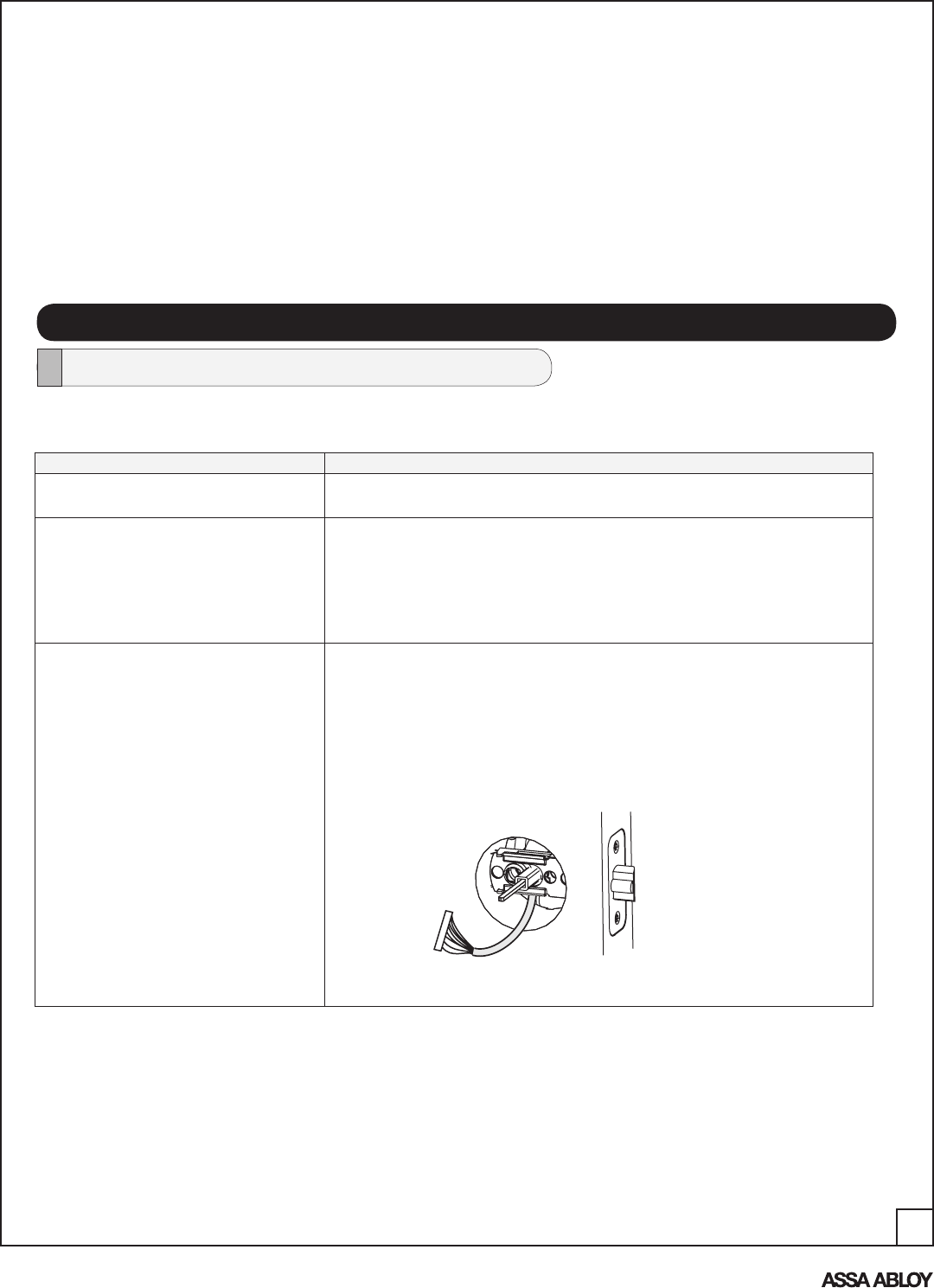
Latch will not deadlock a. Check for sufficient clearance of the latch within the strike-side jamb. Correct this by
increasing the depth of the pocket for the latch.
b. Check for misalignment of latch and/or strike which may be preventing latch from
properly entering the strike. With the door open, extend and retract the latch; if it is
smooth, check the strike alignment.
Latch does not extend or retract smoothly a. Latch and strike are misaligned, see above.
b. Check the backset of door relative to adjustments already made to latch.
c. Verify proper door preparation and re-bore holes that are too small or misaligned.
d. Verify keypad cable/connector is routed under the latch (see Fig. A).
e. Verify latch is installed with correct side up (Fig. A).
Inside of Door
Figure A
Hardware Troubleshooting ......................................................................................17
Programming Troubleshooting ...............................................................................18
Installing the Network Module ...............................................................................19
Change Lever Handing .................................................................................... 20-21
Replace/Install Cylinder .........................................................................................22
Sample Pin Code Management Sheets ........................................................... 23-24
20
An ASSA ABLOY Group brand
P/N AYRT-220-INST-FUL Rev A
Symptom Suggested Action
Lock does not respond – door is open and
accessible.
The touchscreen will become active when pressed with the back of hand or fingers in at least 3 areas
simultaneously.
Use a larger area of the hand or fingers and verify contact with at least 3 areas.
If touchscreen numbers are visible, check to see if they respond when pressed.
Check batteries are installed and oriented correctly in the battery case.
Check batteries are in good condition; replace batteries* if discharged.
Check to see if touchscreen cable is fully connected and not pinched.
Lock does not respond – door is locked and
inaccessible.
Mechanical key will grant access.
Batteries may be completely discharged.
Use mechanical key to gain entry and replace batteries*.
The unit is on for a while, and then shows
no reaction. Lights dim.
The batteries do not have enough power. Replace the batteries*.
Unit chimes to indicate code acceptance,
but the door will not open.
Check to see if there is an existing lock device on the door.
Check the door gaps for any foreign objects between door and frame.
Check that the cable is firmly connected to the PCB.
Unit operates to allow access, but will not
automatically re-lock.
Check to see if Passage Mode** is enabled (Network module units only).
If the Passage Mode icon on the touchscreen and the status indicator on the
interior escutcheon flicker for several seconds, it is set at Passage Mode.
Disable Passage Mode to lock the door.
If low battery indicator is lit, replace batteries*.
PIN codes will not register. PIN codes must consist of 4 to 8 digits to register.
The same PIN code cannot be used for multiple users.
Registration/management of PIN codes is set by the authority of Master Code.
The Master PIN code must be registered prior to adding any users.
Contact the Master user.
User codes must be entered within 20 seconds (while the touchscreen is active) or the process will have
to be restarted.
The star (*) or pound (#) can not be used as part of the PIN code.
Upon entering a PIN code and pressing the
star (*) key, the unit displays an “invalid
code” error or the lock times out without
responding.
Lockout Mode is enabled.
Only the Master Code can enable Lockout Mode.
Contact the Master user.
Upon entering a PIN code and pressing the
(*) key, the red padlock icon appears and
there are different tones.
Check to see if lock is set** at Lockout Mode.
Setting/managing Lockout Mode is done through Master Code only. Contact the Master user.
The unit operates, but it makes
no sound.
Check to see if Silent Mode is enabled (pages 8, 11).
The unit responds “Low Battery” This is the voice alarm alerting that it is time to replace the batteries. Replace all four (4) batteries with
new AA Alkaline batteries*.
Upon entering a PIN code and pressing
the star (*) key, the unit responds “Wrong
number of digits.”
The digits entered were incorrect or incomplete. Re-enter the correct code.
Programming Troubleshooting
* When batteries are replaced, Network Module locks have a real time clock that will be set through the User Interface; it is
recommended to verify correct date and time particularly those locks operating under Daylight Saving Time (DST).
** Network module units only
21
An ASSA ABLOY Group brand
P/N AYRT-220-INST-FUL Rev A
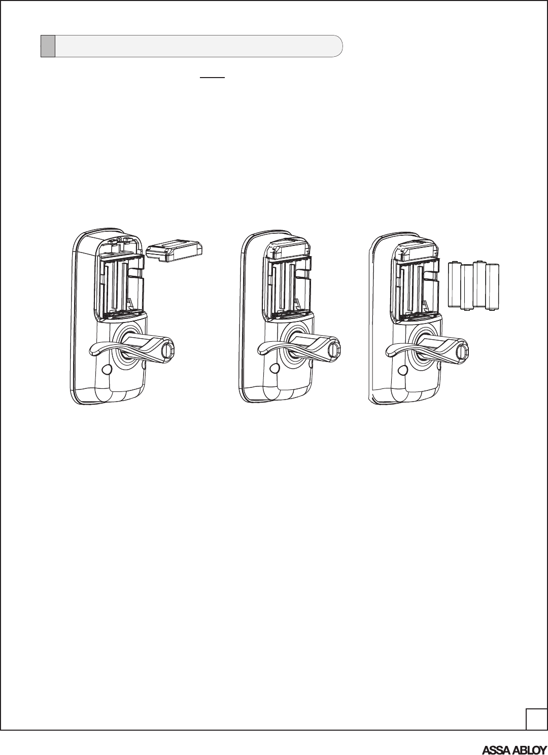
IMPORTANT: The batteries must be removed prior to removing and/or inserting the
network module:
• Remove batteries
• Remove and/or insert network module
• Reinstall batteries
Installing the Network Module
Use Feature Programming step 7 (page 16) for enrollment of the Network Module.
22
An ASSA ABLOY Group brand
P/N AYRT-220-INST-FUL Rev A
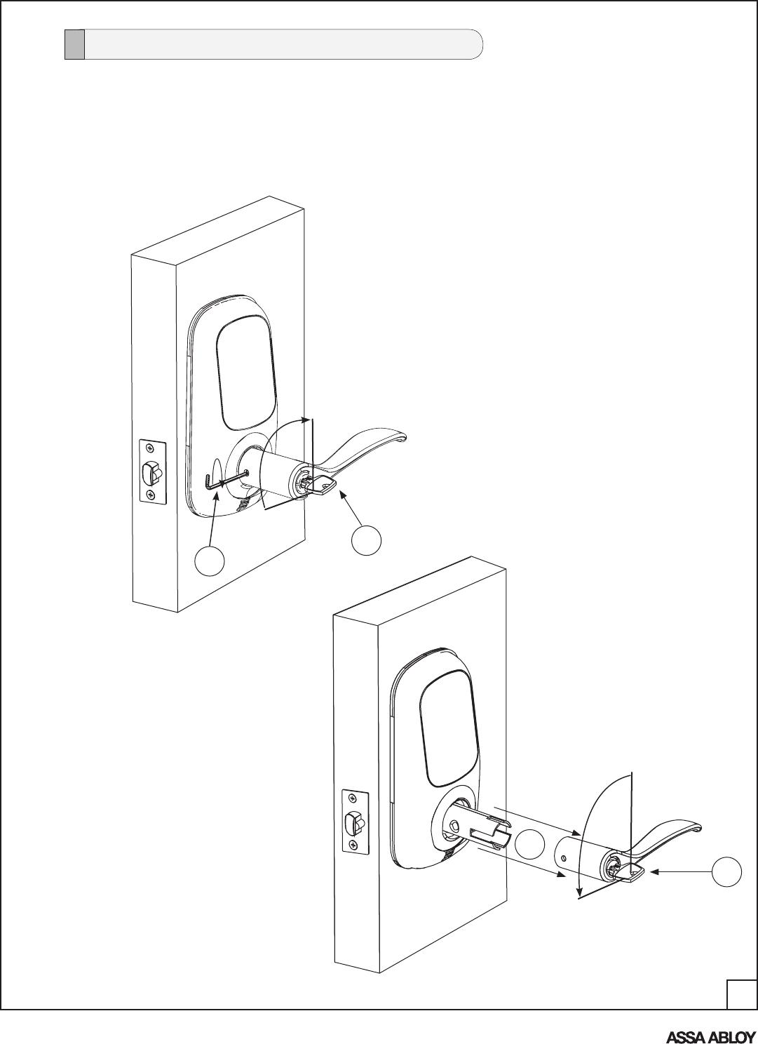
How to Change Handing of Lever (Reverse Levers)
1. Remove the outside lever handle:
A. Insert key in cylinder (outside lever handle); rotate key 90° clockwise.
B. Insert allen wrench (included) in set screw on side of lever (toward edge of
door); turn clockwise to loosen.
C. Pull to remove lever handle/key/cylinder.
B
CCW
F
C
90°
A
90°
23
An ASSA ABLOY Group brand
P/N AYRT-220-INST-FUL Rev A
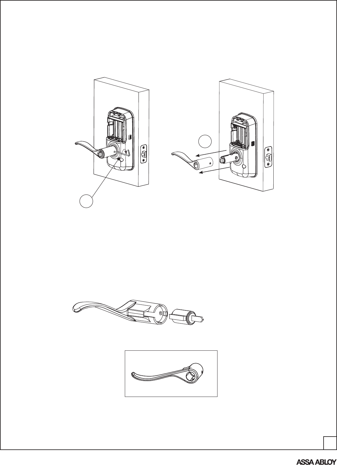
2. Remove the inside lever handle:
A. Insert allen wrench (included) in set screw on side of lever
(towards edge of door); turn clockwise to loosen lever handle.
B. Pull to remove lever handle.
A
A. Remove and switch handles (inside to outside, outside to inside).
B. Remove cylinder from outside lever handle.
C. Insert cylinder in "new" outside lever (Fig. 3A).
D. Push handle in allowing holes for set screw to align.
E. Insert set screw and tighten by turning set screw counter-clockwise.
3. Change the lever handing:
Incorrect
NOTE: "Swoop" of lever handle
must be oriented in upward direction
as shown in Fig. 3A
Correct
Figure 3A
B
Figure 3B

24
An ASSA ABLOY Group brand
P/N AYRT-220-INST-FUL Rev A
1. Remove cylinder:
A. Repeat previous steps for removing the outside lever handle.
B. Remove cylinder.
How to Replace or Install Cylinder
2. Install new cylinder:
A. Insert cylinder in "new" outside lever.
B. Push handle in allowing holes for set screw to align.
C. Insert set screw and tighten by turning set screw counter-clockwise.
D. Verify that new cylinder fits and rotates freely.
E. Test operation of the new cylinder/key.`
25
An ASSA ABLOY Group brand
P/N AYRT-220-INST-FUL Rev A
PIN CODE MANAGEMENT SAMPLE SHEETS
PIN Code Management (No Network Module - Up to 25 Users)
Location: Door Number: User User Name User # PIN Code
User Type User Name User # PIN Code
Master User 13
User 01 User 14
User 02 User 15
User 03 User 16
User 04 User 17
User 05 User 18
User 06 User 19
User 07 User 20
User 08 User 21
User 09 User 22
User 10 User 23
User 11 User 24
User 12 User 25
26
An ASSA ABLOY Group brand
P/N AYRT-220-INST-FUL Rev A
PIN Code Management (With Network Module - Up to 250 Users) - Duplicate Sheet to record entries
User Type User Name User # PIN Code User User Name User # PIN Code
Master User ___
User ___ User ___
User ___ User ___
User ___ User ___
User ___ User ___
User ___ User ___
User ___ User ___
User ___ User ___
User ___ User ___
User ___ User ___
User ___ User ___
User ___ User ___
User ___ User ___
User ___ User ___
User ___ User ___
User ___ User ___
User ___ User ___
User ___ User ___
User ___ User ___
User ___ User ___
User ___ User ___
User ___ User ___
User ___ User ___
User ___ User ___
User ___ User ___
User ___ User ___
User ___ User ___
User ___ User ___
User ___ User ___
User ___ User ___
User ___ User ___
User ___ User ___
User ___ User ___
User ___ User ___
User ___ User ___
User ___ User ___
User ___ User ___
User ___ User ___
User ___ User ___
User ___ User ___
User ___ User ___
User ___ User ___
User ___ User ___
User ___ User ___

ONLINE LITERATURE AND TEMPLATES
For the latest information on Yale products visit our website at
www.yalelocks.com. Click on the “Literature” button to find the
most up-to-date catalogs, parts manuals, templates, specifica-
tions and installation instructions.
Yale Locks & Hardware
100 Yale Avenue, Lenoir City, TN 37771 • Product Support Tel 800.810.WIRE (9473) • www.yalelocks.com
Yale Locks & Hardware is a division of Yale Security Inc., an ASSA ABLOY Group company.
Yale® is a registered trademark of Yale Security Inc., an ASSA ABLOY Group company. All rights reserved. Yale Real Living™ is a trademark of
Copyright © 2012, Yale Security Inc., an ASSA ABLOY Group company. All rights reserved. Reproduction in whole or in part without express
written permission of Yale Security Inc., an ASSA ABLOY Group company is prohibited.
YALE, with its unique global reach and range of products, is the world’s favorite lock — the preferred solution for securing your home, family
and personal belongings.
ASSA ABLOY is the global leader in door opening solutions, dedicated to satisfying end-user needs for security, safety and convenience.
An ASSA ABLOY Group brand
P/N AYRT-220-INST-FUL Rev A